1
RNXV Evaluation Kit
User’s Guide
2013 Microchip Technology Inc.
DS50002204A
Note the following details of the code protection feature on Microchip devices:
•
Microchip products meet the specification contained in their particular Microchip Data Sheet.
•
Microchip believes that its family of products is one of the most secure families of its kind on the market today, when used in the
intended manner and under normal conditions.
•
There are dishonest and possibly illegal methods used to breach the code protection feature. All of these methods, to our
knowledge, require using the Microchip products in a manner outside the operating specifications contained in Microchip’s Data
Sheets. Most likely, the person doing so is engaged in theft of intellectual property.
•
Microchip is willing to work with the customer who is concerned about the integrity of their code.
•
Neither Microchip nor any other semiconductor manufacturer can guarantee the security of their code. Code protection does not
mean that we are guaranteeing the product as “unbreakable.”
Code protection is constantly evolving. We at Microchip are committed to continuously improving the code protection features of our
products. Attempts to break Microchip’s code protection feature may be a violation of the Digital Millennium Copyright Act. If such acts
allow unauthorized access to your software or other copyrighted work, you may have a right to sue for relief under that Act.
Information contained in this publication regarding device
applications and the like is provided only for your convenience
and may be superseded by updates. It is your responsibility to
ensure that your application meets with your specifications.
MICROCHIP MAKES NO REPRESENTATIONS OR
WARRANTIES OF ANY KIND WHETHER EXPRESS OR
IMPLIED, WRITTEN OR ORAL, STATUTORY OR
OTHERWISE, RELATED TO THE INFORMATION,
INCLUDING BUT NOT LIMITED TO ITS CONDITION,
QUALITY, PERFORMANCE, MERCHANTABILITY OR
FITNESS FOR PURPOSE. Microchip disclaims all liability
arising from this information and its use. Use of Microchip
devices in life support and/or safety applications is entirely at
the buyer’s risk, and the buyer agrees to defend, indemnify and
hold harmless Microchip from any and all damages, claims,
suits, or expenses resulting from such use. No licenses are
conveyed, implicitly or otherwise, under any Microchip
intellectual property rights.
Trademarks
The Microchip name and logo, the Microchip logo, dsPIC,
FlashFlex, KEELOQ, KEELOQ logo, MPLAB, PIC, PICmicro,
PICSTART, PIC32 logo, rfPIC, SST, SST Logo, SuperFlash
and UNI/O are registered trademarks of Microchip Technology
Incorporated in the U.S.A. and other countries.
FilterLab, Hampshire, HI-TECH C, Linear Active Thermistor,
MTP, SEEVAL and The Embedded Control Solutions
Company are registered trademarks of Microchip Technology
Incorporated in the U.S.A.
Silicon Storage Technology is a registered trademark of
Microchip Technology Inc. in other countries.
Analog-for-the-Digital Age, Application Maestro, BodyCom,
chipKIT, chipKIT logo, CodeGuard, dsPICDEM,
dsPICDEM.net, dsPICworks, dsSPEAK, ECAN,
ECONOMONITOR, FanSense, HI-TIDE, In-Circuit Serial
Programming, ICSP, Mindi, MiWi, MPASM, MPF, MPLAB
Certified logo, MPLIB, MPLINK, mTouch, Omniscient Code
Generation, PICC, PICC-18, PICDEM, PICDEM.net, PICkit,
PICtail, REAL ICE, rfLAB, Select Mode, SQI, Serial Quad I/O,
Total Endurance, TSHARC, UniWinDriver, WiperLock, ZENA
and Z-Scale are trademarks of Microchip Technology
Incorporated in the U.S.A. and other countries.
SQTP is a service mark of Microchip Technology Incorporated
in the U.S.A.
GestIC and ULPP are registered trademarks of Microchip
Technology Germany II GmbH & Co. & KG, a subsidiary of
Microchip Technology Inc., in other countries.
All other trademarks mentioned herein are property of their
respective companies.
© 2013, Microchip Technology Incorporated, Printed in the
U.S.A., All Rights Reserved.
Printed on recycled paper.
ISBN: 978-1-62077-691-9
QUALITYMANAGEMENTSYSTEM
CERTIFIEDBYDNV
== ISO/TS16949==
DS50002204A-page 2
Microchip received ISO/TS-16949:2009 certification for its worldwide
headquarters, design and wafer fabrication facilities in Chandler and
Tempe, Arizona; Gresham, Oregon and design centers in California
and India. The Company’s quality system processes and procedures
are for its PIC® MCUs and dsPIC® DSCs, KEELOQ® code hopping
devices, Serial EEPROMs, microperipherals, nonvolatile memory and
analog products. In addition, Microchip’s quality system for the design
and manufacture of development systems is ISO 9001:2000 certified.
2013 Microchip Technology Inc.
RNXV Evaluation Kit User’s Guide
Object of Declaration: RNXV Evaluation Kit
2013 Microchip Technology Inc.
DS50002204A-page 3
RNXV Evaluation Kit User’s Guide
NOTES:
2013 Microchip Technology Inc.
DS50002204A-page 4
RNXV EVALUATION KIT
USER’S GUIDE
Table of Contents
Preface ......................................................................................................................... 7
Chapter 1. Overview
1.1 Introduction ................................................................................................ 13
1.2 RN-XV-EK1 Evaluation Kit Features ......................................................... 13
1.3 RN-XV-EK1 Evaluation Kit Contents and Part Details .............................. 14
1.4 RN-XV-EK1 Evaluation Board Contents ................................................... 14
1.5 RN-XV-EK1 Evaluation Kit Related Demo Applications ............................ 16
Chapter 2. Getting Started
2.1 Introduction ................................................................................................ 17
2.2 Hardware Requirements ........................................................................... 17
2.3 Software/Utility Requirements ................................................................... 18
2.4 Modules Configuration .............................................................................. 18
Chapter 3. Application Interface Concerns
3.1 Introduction ................................................................................................ 25
3.2 RN171XV Module Concerns ..................................................................... 25
3.3 RN41/42XV Module Concerns .................................................................. 26
Appendix A. RN-XV-EK1 Evaluation Board Schematic and PCB Details
A.1 Introduction ............................................................................................... 29
A.2 RN-XV-EK1 Evaluation Board Schematic ................................................. 29
A.3 RN-XV-EK1 Evaluation Board PCB Layout .............................................. 31
A.4 RN-XV-EK1 Evaluation Board Bill of Materials ......................................... 35
A.5 RN-XV-EK1 Physical Dimensions ............................................................. 36
Worldwide Sales and Service .................................................................................. 37
DS50002204A-page 5
2013 Microchip Technology Inc.
RNXV Evaluation Kit User’s Guide
NOTES:
DS50002204A-page 6
2013 Microchip Technology Inc.
RNXV EVALUATION KIT
USER’S GUIDE
Preface
NOTICE TO CUSTOMERS
All documentation becomes dated, and this manual is no exception. Microchip tools and
documentation are constantly evolving to meet customer needs, so some actual dialogs
and/or tool descriptions may differ from those in this document. Please refer to our web site
(www.microchip.com) to obtain the latest documentation available.
Documents are identified with a “DS” number. This number is located on the bottom of each
page, in front of the page number. The numbering convention for the DS number is
“DSXXXXXA”, where “XXXXX” is the document number and “A” is the revision level of the
document.
For the most up-to-date information on development tools, see the MPLAB® IDE online help.
Select the Help menu, and then Topics to open a list of available online help files.
INTRODUCTION
This chapter contains general information that will be useful to know before using the
RNXV Evaluation Kit User’s Guide. Items discussed in this chapter include:
•
•
•
•
•
•
•
•
Document Layout
Conventions Used in this Guide
Warranty Registration
Recommended Reading
The Microchip Web Site
Development Systems Customer Change Notification Service
Customer Support
Document Revision History
DOCUMENT LAYOUT
This document describes how to use the RNXV Evaluation Kit. The manual layout is as
follows:
• Chapter 1. “Overview” – This chapter describes the RN-XV-EK1 as an evaluation
kit which supports the RNXV series of modules for both Wi-Fi® and Bluetooth® platforms. The board connects to a PC via a standard USB cable which is included in
the kit, and provides two push button switches to control WPS mode and to reset
the RN171XV module.
• Chapter 2. “Getting Started” – This chapter describes the hardware and software setup required to evaluate the RNXV series modules using the RN-XV-EK1
evaluation board. The RNXV modules (sold separately) mount on the evaluation
board and contain either the RN171 or RN41/RN42 modules depending on the
part number.
2013 Microchip Technology Inc.
DS50002204A-page 7
RNXV Evaluation Kit User’s Guide
• Chapter 3. “Application Interface Concerns” – This chapter provides design
concerns related to powering the evaluation board, sensor interface settings,
mode settings, and restoring factory settings for RN171XV and RN41/42XV modules mounted on RNXV Evaluation Board.
• Appendix A. “RN-XV-EK1 Evaluation Board Schematic and PCB Details” –
This appendix provides the RN-XV-EK1 Evaluation Boards schematic, PCB layout
and Bill of Materials (BOM).
CONVENTIONS USED IN THIS GUIDE
This manual uses the following documentation conventions:
DOCUMENTATION CONVENTIONS
Description
Arial font:
Italic characters
Represents
Referenced books
Emphasized text
A window
A dialog
A menu selection
A field name in a window or
dialog
A menu path
MPLAB® IDE User’s Guide
...is the only compiler...
the Output window
the Settings dialog
select Enable Programmer
“Save project before build”
A dialog button
A tab
A key on the keyboard
Click OK
Click the Power tab
Press <Enter>, <F1>
Italic Courier New
Sample source code
Filenames
File paths
Keywords
Command-line options
Bit values
Constants
A variable argument
Square brackets [ ]
Optional arguments
Curly brackets and pipe
character: { | }
Ellipses...
Choice of mutually exclusive
arguments; an OR selection
Replaces repeated text
#define START
autoexec.bat
c:\mcc18\h
_asm, _endasm, static
-Opa+, -Opa0, 1
0xFF, ‘A’
file.o, where file can be
any valid filename
mcc18 [options] file
[options]
errorlevel {0|1}
Initial caps
Quotes
Underlined, italic text with
right angle bracket
Bold characters
Text in angle brackets < >
Courier New font:
Plain Courier New
Represents code supplied by
user
DS50002204A-page 8
Examples
File>Save
var_name [,
var_name...]
void main (void)
{ ...
}
2013 Microchip Technology Inc.
Preface
WARRANTY REGISTRATION
Please complete the enclosed Warranty Registration Card and mail it promptly.
Sending in the Warranty Registration Card entitles you to receive new product updates.
Interim software releases are available at the Microchip web site.
RECOMMENDED READING
This user’s guide describes how to use the RNXV Evaluation Board. Other useful
documents are listed below. The following Microchip documents are available and
recommended as supplemental reference resources.
RN171 Module Data Sheet (DS75084)
RN171XV Module Data Sheet
RN41 Module Data Sheet
RN42 Module Data Sheet
RN41XV-RN42XV Module Data Sheet
PICDEM™ PIC18 Explorer Demonstration Board User’s Guide (DS51721)
Explorer 16 Development Board User’s Guide (DS51589)
WiFly Command Reference, Advanced Features and Appplications User’s Guide
2013 Microchip Technology Inc.
DS50002204A-page 9
RNXV Evaluation Kit User’s Guide
THE MICROCHIP WEB SITE
Microchip provides online support through our web site at http://www.microchip.com.
This web site is used as a means to make files and information easily available to
customers. Accessible by using your favorite Internet browser, the web site contains
the following information:
• Product Support – Data sheets and errata, application notes and sample
programs, design resources, user’s guides and hardware support documents,
latest software releases and archived software
• General Technical Support – Frequently Asked Questions (FAQs), technical
support requests, online discussion groups, Microchip consultant program
member listing
• Business of Microchip – Product selector and ordering guides, latest Microchip
press releases, listing of seminars and events, listings of Microchip sales offices,
distributors and factory representatives
DEVELOPMENT SYSTEMS CUSTOMER CHANGE NOTIFICATION SERVICE
Microchip’s customer notification service helps keep customers current on Microchip
products. Subscribers will receive e-mail notification whenever there are changes,
updates, revisions or errata related to a specified product family or development tool of
interest.
To register, access the Microchip web site at http://www.microchip.com, click
Customer Change Notification and follow the registration instructions.
The Development Systems product group categories are:
• Compilers – The latest information on Microchip C compilers and other language
tools. These include the MPLAB® C compiler; MPASM™ and MPLAB 16-bit
assemblers; MPLINK™ and MPLAB 16-bit object linkers; and MPLIB™ and
MPLAB 16-bit object librarians.
• Emulators – The latest information on the Microchip MPLAB REAL ICE™ in-circuit emulator.
• In-Circuit Debuggers – The latest information on the Microchip in-circuit debugger, MPLAB ICD 3.
• MPLAB® IDE – The latest information on Microchip MPLAB IDE, the Windows®
Integrated Development Environment for development systems tools. This list is
focused on the MPLAB IDE, MPLAB SIM simulator, MPLAB IDE Project Manager
and general editing and debugging features.
• Programmers – The latest information on Microchip programmers. These include
the MPLAB PM3 device programmers and the PICkit™ 3 development
programmers.
CUSTOMER SUPPORT
Users of Microchip products can receive assistance through several channels:
•
•
•
•
Distributor or Representative
Local Sales Office
Field Application Engineer (FAE)
Technical Support
Customers should contact their distributor, representative or FAE for support. Local
sales offices are also available to help customers. A listing of sales offices and
locations is included in the back of this document.
Technical support is available through our web site at: http://support.microchip.com
DS50002204A-page 10
2013 Microchip Technology Inc.
Preface
DOCUMENT REVISION HISTORY
Revision A (December 2013)
This is the initial released version of the document.
2013 Microchip Technology Inc.
DS50002204A-page 11
RNXV Evaluation Kit User’s Guide
NOTES:
DS50002204A-page 12
2013 Microchip Technology Inc.
RNXV EVALUATION KIT
USER’S GUIDE
Chapter 1. Overview
1.1
INTRODUCTION
The RN-XV-EK1 is an evaluation kit to support the RNXV series of modules for both
Wi-Fi® and Bluetooth® platforms. The board connects to a PC via a standard USB
cable which is included in the kit, and provides 2 push button switches to control WPS
mode and to reset the RN171XV module. The board has connectors to connect to the
RNXV module, as well as headers that enables prototyping. It is compatible with all
RNXV antenna options. The kit does not include any RNXV modules.
The RNXV modules have certified Bluetooth or Wi-Fi connectivity which are helpful in
replacing the existing systems with 802.15.4 modules. The RNXV modules are
pre-loaded with firmware to simplify integration and minimize applications development
time. The modules are based on the popular 2 x 10 (2mm) socket footprint often found
in embedded applications.
The RNXV Evaluation Kit details can be downloaded from the Microchip web site
http://www.microchip.com/RN-XV-EK1.
This chapter discusses the following topics:
•
•
•
•
1.2
RN-XV-EK1 Evaluation Kit Features
RN-XV-EK1 Evaluation Kit Contents and Part Details
RN-XV-EK1 Evaluation Board Contents
RN-XV-EK1 Evaluation Kit Related Demo Applications
RN-XV-EK1 EVALUATION KIT FEATURES
The RNXV Evaluation Kit has the following features:
• Supports ultra low-power FCC/CE/IC certified 2.4 GHz IEEE 802.11b/g RN171
module through RN171XV
• Supports low-power FCC/CE/IC certified 2.4 GHz IEEE 802.15.1 RN41/42 modules through RN41/42XV
• Supports several antenna options, depending on the RN171XV, RN41XV and
RN42XV modules selected
• Powers up RN171XV, RN41XV and RN42XV modules
• Supports WPS (FN) push button for easy configuration of RN171XV module
• Reset (RST) push button wakes the RN171XV module
• Standard USB mini connector
• Hardware interface: USB via FTDI chip
• Brings the RNXV signals out on headers for easy debugging
• The evaluation board’s moisture sensitivity level (MSL) is 1
• Size - 1.58” x 1” x 0.25”
• Weight - Approx. 6.5 g
2013 Microchip Technology Inc.
DS50002204A-page 13
RNXV Evaluation Kit User’s Guide
1.3
RN-XV-EK1 EVALUATION KIT CONTENTS AND PART DETAILS
The package kit contents contain the following development tools listed in Table 1-1
with part number details.
TABLE 1-1:
RNXV EVALUATION KIT CONTENTS
Description
RNXV Evaluation Board
Part Number
RN-XV-EK1
USB cable
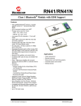
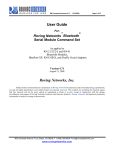
Figure 1-1 illustrates the evaluation kit contents of RN-XV-EK1.
FIGURE 1-1:
RNXV EVALUATION KIT CONTENTS
RN-XV-EK1
RNXV Evaluation board for the
RN171 module with USB cable
Note:
1.4
The RNXV modules such as RN171XV, RN41XV or RN42XV are sold separately and are not
part of the standard RN-XV-EK1 Evaluation Kit.
RN-XV-EK1 EVALUATION BOARD CONTENTS
This section describes the hardware for RN-XV-EK1 Evaluation board, which enables
user to evaluate the RNXV modules. The RNXV modules, which are sold separately, is
mounted on the evaluation board and contains the RNXV Wi-Fi or Bluetooth.
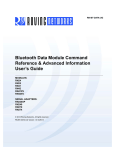
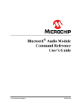
Figure 1-2 shows the RN-XV-EK1 components.
DS50002204A-page 14
2013 Microchip Technology Inc.
Overview
FIGURE 1-2:
Note:
RN-XV-EK1 EVALUATION BOARD COMPONENTS
All GPIOs and Sensor interfaces referenced are for RN-171 module.
2013 Microchip Technology Inc.
DS50002204A-page 15
RNXV Evaluation Kit User’s Guide
Table 1-2 gives details on the hardware availability with module interface.
TABLE 1-2:
RNXV EVALUATION KIT HARDWARE AVAILABILITY WITH MODULE INTERFACE
Hardware
Description
RN-XV-EK1 with
RN171XV
RN-XV-EK1 with
RN41/42XV
Evaluation Board
Contains connectors for Wi-Fi/Bluetooth
modules.
For RN171 Module
For RN41/42
module
Power-Up
Interface for powering up the evaluation
boards.
USB
USB
Push Buttons
To enter RESET and WPS (Wi-Fi Protected
Setup) mode in RN171XV module.
Available
Available
Communication Interface UART and USB
Available
Available
USB Connector
On-board
Provides power to the evaluation board and
supports communication (COM Port).
Available
Available
Antenna Connections
Supported by RNXV modules based on the
module selected.
No
No
1.5
RN-XV-EK1 EVALUATION KIT RELATED DEMO APPLICATIONS
Resources related to RN-XV-EK1 can be downloaded from the Microchip web site
http://www.microchip.com/RN-XV-EK1.
Note:
DS50002204A-page 16
For details on working with RN171 module firmware, refer to “WiFly Command Reference, Advanced Features and Applications User’s Guide”; and
for RN41/41 module, refer to the Bluetooth Command Reference &
Advanced Information User’s Guide from the Microchip web site
http://www.microchip.com.
2013 Microchip Technology Inc.
RNXV EVALUATION KIT
USER’S GUIDE
Chapter 2. Getting Started
2.1
INTRODUCTION
This chapter describes the hardware and software setup required to evaluate the
RNXV series modules using the RN-XV-EK1 evaluation board. The RNXV modules
(sold separately) mount on the evaluation board and contain either the RN171 or
RN41/RN42 modules depending on the part number. The board connects to a PC or
embedded controllers via the standard USB cable serial port interface. The evaluation
board also provides two push button switches to control (Wi-Fi Protected Setup) WPS
mode and to reset the module without any software configuration while using RN171XV
module. The board has connectors to drop in the RNXV, as well as headers that enable
wires access to the RNXV signals.
This chapter discusses the following topics:
• Hardware Requirements
• Software/Utility Requirements
• Modules Configuration
2.2
HARDWARE REQUIREMENTS
The RN-XV-EK1 requires RN171XV or RN41XV/RN42XV boards along with an USB
cable as its hardware setup for connection with PC/laptop and to run the demo applications.
The following are the steps to setup the Evaluation Board demo:
1. Mount RN171XV or RN41/42XV to RN-XV-EK1 evaluation board on the available connector headers.
2. Power-up the modules/board through the USB cable via computer/laptop.
3. Download and install the FTDI drivers from the Microchip web site.
4. Once the FTDI drivers are installed, the COM port is automatically assigned based
on the active connection.
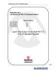
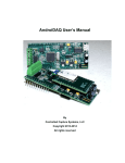
Figure 2-1 shows the completed RN-VX-EK1 evaluation board hardware setup with
RN171XV board (RN171 as module base).
2013 Microchip Technology Inc.
DS50002204A-page 17
RNXV Evaluation Kit User’s Guide
FIGURE 2-1:
2.3
HARDWARE SETUP WITH RN171XV BOARD
SOFTWARE/UTILITY REQUIREMENTS
The following software tools/utilities are required to run the demo applications:
• Terminal Emulator Application such as TeraTerm (for Windows OS) or CoolTerm (for
MAC OS). The Terminal Emulator program is used to send the configuration commands to the module over a UART interface. The emulator also displays information
transmitted from the module.
• RN-XV-EK1 board uses the FTDI chip set. Windows automatically installs the drivers
for the USB-serial cable. If the drivers are not automatically installed, download and
install the FTDI drivers from the Microchip web site “http://ww1.microchip.com/downloads/en/DeviceDoc/FTDI-Drivers.zip” FTDI Chipset Drivers.
• Once the FTDI drivers are installed, the COM port is automatically assigned based on
the active connection.
2.4
MODULES CONFIGURATION
RN171XV CONFIGURATION
RN171XV with RN171 as module base is mounted on RNXV Evaluation Kit. The RN171
operates in two modes:
• Data mode (default)
• Command mode
2.4.1
Data Mode
In Data mode, the RN171 module is essentially a data pipe. When the module receives
data over Wi-Fi, it strips the TCP/IP or UDP headers and trailers, and passes the user payload data to the UART. When data is written to the UART, the module constructs the TCP/IP
packet and sends it out over Wi-Fi. Thus, the entire process of sending/receiving data to
the host is transparent to the end application/user microcontroller.
DS50002204A-page 18
2013 Microchip Technology Inc.
Getting Started
FIGURE 2-2:
APPLICATION INTERFACE FOR DATA AND COMMAND MODES
2.4.2
Command Mode
By default, the RN171 module is in Data mode. Sending an escape sequence $$$
causes the module to enter the Command mode. Once in Command mode, the module
can be configured using simple ASCII commands. To exit Command mode and return to
the Data mode, type exit <cr>. Figure 2-2 shows an application interface for Data and
Command modes.
Basic configuration requires the wireless network access point’s name (SSID) and the
authentication password. The RN171 module can associate with only one network at a
time. It is recommended to begin evaluation by configuring the RN171 module using an
open access point to simplify the setup.
The following two methods are used to configure the RN171 module:
1. Over the UART, that is connected to a computer/laptop or to a microcontroller
2. Through Wi-Fi using Ad hoc networking
Terminal emulator utility is required to type the commands and to monitor the
activity/transactions.
2013 Microchip Technology Inc.
DS50002204A-page 19
RNXV Evaluation Kit User’s Guide
2.4.3
Configuration Using a USB Cable
The evaluation board uses a USB cable to enable the host computer to communicate
with the RN171 module on the evaluation board. The procedures in this section describe
how to use a terminal emulator to go into Configuration mode, send commands to find
networks, associate with an access point, and save configuration.
2.4.3.1
CONFIGURE THE MODULE USING A TERMINAL EMULATOR
Either the TeraTerm (for Windows OS) or CoolTerm (for Mac OS-X), terminal emulator
utility can be used. Also legacy evaluation boards use a USB-to-serial cable for connecting the evaluation board with the computer/laptop. When using the RN171 evaluation board, use the COM port to which the USB-to-serial cable is connected.
The following are the steps to communicate with the module using a terminal emulator:
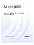
1. Determine the COM port that is assigned to the USB cable (the port is COM9 in
the example shown in Figure 2-3).
2. Open the available terminal emulation program and specify the COM port.
3. When using TeraTerm, go to Serial option and select the COM port number from
the drop-down menu.
4. The serial port with the required settings are as follows:
- Baud: 9600
- Data bits: 8
- Parity: None
- Stop bits: 1
- Flow control: None
5. Type the commands through the terminal emulator program and to the assigned
program.
Note:
The COM port number is found in the following location path:
- For Windows OS: Open Computer Management. Click on System
Tools>Device Manager. Browse to Ports (COM & LPT) and expand the selection for serial ports. Use TeraTerm for other configuration settings and monitoring. This is illustrated in Figure 2-3.
- For MAC OS: When using CoolTerm, view and select the port from the same
terminal emulator application.
DS50002204A-page 20
2013 Microchip Technology Inc.
Getting Started
FIGURE 2-3:
2.4.3.2
FINDING THE COM PORT NUMBER IN WINDOWS
ENTER COMMAND MODE
The following are the steps to enter the Command mode in a terminal emulator:
1. Type $$$ on the keyboard sequentially with no additional characters before or
after each $ sign. The module replies with CMD (on terminal emulator) to indicate
that it is in Command mode.
2. Type show net <cr> to display the current network settings (Figure 2-4 shows
the current network settings for version 2.28).
Note:
FIGURE 2-4:
When a command is completed, the terminal displays a prompt using the
format <X.XX>, where X.XX indicates the module’s firmware version.
CURRENT NETWORK SETTINGS
2013 Microchip Technology Inc.
DS50002204A-page 21
RNXV Evaluation Kit User’s Guide
The RN171 module supports a variety of command keywords. The WiFly Command
Reference, Advanced Features and Applications User’s Guide from the Microchip web
site http://www.microchip.com provides a complete list of command reference.
RN41/42XV CONFIGURATION
RN41/42XV with RN41/42 module base is mounted on RNXV Evaluation Kit. The
RN41/42 also operates in two modes:
• Data mode (default)
• Command mode
While in Data mode, the module operates as a data pipe. When the module receives
data, it strips the Bluetooth headers and trailers and passes the user data to the UART
port. When data is written to the UART port, the module constructs the Bluetooth packet
and sends it out over the Bluetooth wireless connection. Thus, the entire process of
sending/receiving data to the host is transparent to the end microcontroller. The
Figure 2-5 illustrates the operational modes.
FIGURE 2-5:
DATA & COMMAND MODES
The default configuration for the Bluetooth module is:
•
•
•
•
•
Bluetooth slave mode
Bluetooth pin code 1234
Serial port 115,200 Kbps baud rate, 8 bits, no parity, 1 stop bit
Serial port flow control disabled
Low-power mode off
Configuration is done by putting the module in the Command mode and sending ASCII
commands over the UART port or the Bluetooth link. Reboot the module for settings to take
effect. The changed configuration parameters persist until next change happens or until a
factory reset is performed.
There are two ways to configure the Bluetooth module:
• Local configuration using computer’s serial port
• Via Bluetooth
Terminal emulator utility is required to type the commands and to monitor the activity/
transactions.
DS50002204A-page 22
2013 Microchip Technology Inc.
Getting Started
2.4.4
Configuring the Module over the UART Port
Connect the module to any computer/laptop. Connection can be done using the
RS-232 DB9 port or via a USB cable. When RN-XV-EK1 evaluation board is used as
RN41/42XV base board, connection is done using a USB cable.
With the Bluetooth module connected and powered on, run a terminal emulator and
open the COM port to which the cable is connected. The terminal emulator’s communication settings must be the default serial port settings:
•
•
•
•
•
Baud rate 115,200 kbps
8 bits
No parity
1 stop bit
Hardware flow control enabled
Note:
Use local configuration at any time when the module does NOT have a
Bluetooth connection, as well as under certain conditions. If the module is
in Configuration mode and a connection occurs, the module exits the Configuration mode and data passes back and forth from the remote module.
Once a connection is made, Command mode can be entered only if the boot-up configuration timer has not expired (60 seconds). To remain in Configuration mode, set the
configuration timer to 225.
2.4.5
Remote Configuration Using Bluetooth
It is often useful to configure the module remotely over a Bluetooth connection. Before
performing remote configuration using Bluetooth, first pair the Bluetooth module with
any computer. For computer/laptop with Bluetooth capability and running Windows,
click Bluetooth devices in the system tray at the bottom right of the computer screen.
Select Add a Bluetooth device and follow the on-screen instructions. For Mac OS-X,
click the Bluetooth icon, select Setup Bluetooth device and follow the on-screen
instructions. Once a connection is made, the module enters the command mode if the
boot-up configuration timer has not expired (60 seconds). To remain in Configuration
mode, set the configuration timer to 255.
When the configuration is finished, reset the module or send the --- command, which
causes the module to exit Configuration mode and enables data to pass normally.
Note:
2.4.6
Configuration mode (local or remote) is NEVER enabled when the module
is in auto-mode and is connected over Bluetooth.
Enter Command Mode
To enter Command mode, launch a terminal emulator and specify the module’s default
settings. Table 2-1 shows the serial port settings.
TABLE 2-1:
SERIAL PORT SETTINGS
Setting
Value
Port
COM port to which module is attached
Baud rate
115200
Data rate
8 bits
Patiry
None
Stop bits
1
Flow control
None
2013 Microchip Technology Inc.
DS50002204A-page 23
RNXV Evaluation Kit User’s Guide
Type $$$ into the terminal emulator to enter Command mode.
The module returns the string CMD, which indicates that the connection and terminal
settings are correct. While in Command mode, the module accepts ASCII bytes as
commands. When a valid command is entered, the module returns AOK. It returns ERR
for an invalid command and ? for unrecognized commands. Type h <cr> to see a list
of commands.
A quick check to confirm that user has entered the Command mode is to type the X <cr>
command after entering Command mode. This command shows summary of the module’s current settings, such as the Bluetooth name, device class and serial port settings.
Figure 2-6 illustrates the view of current settings.
FIGURE 2-6:
VIEW CURRENT SETTINGS
To return to data mode, type --- <cr> or reset the module and re-connect.
The RN41/42 modules support a variety of command keywords. The Bluetooth Data Module Command Reference & Advanced Information User’s Guide from the Microchip web
site http://www.microchip.com/bluetooth provides a complete list of command reference.
DS50002204A-page 24
2013 Microchip Technology Inc.
RNXV EVALUATION KIT
USER’S GUIDE
Chapter 3. Application Interface Concerns
3.1
INTRODUCTION
This section provides the design concerns related to powering the evaluation board,
sensor interface settings, mode settings and restoring factory settings for RN171XV
and RN41/42XV modules mounted on RNXV Evaluation Board.
3.2
RN171XV MODULE CONCERNS
3.2.1
Powering the Module
The RN171XV module is powered using 5V supplied from USB host connected to
RN-XV-EK1 board.
3.2.2
Sensor Interfaces
The module input voltage on the sensor inputs must not exceed 1.2V. The Analog-to-Digital Converter (ADC) saturates at 400 mV. It is recommended to use the sensor power output to drive analog devices that are attached to the sensor pins.
Note:
3.2.3
The RN-XV adds an extra voltage divider on the SENSOR inputs. Sensor
pins 2 and 3 have a resistor network (using 400 kohms and 100 kohms) in
front of sensors 4 and 5, respectively. Hence, the SENSOR inputs on the
RN-XV saturate the ADC at 2280mV and can accept up to 5V.
Sensor Inputs
For RN-171-XV connector pins 13, 15, 18, and 19 can be configured as GPIO pins or sensor inputs, depending on the installed resistors.
• Sensor inputs - Pins 19 and 20
• GPIOs - Pins 13, 15, and 18
For details, refer to “RN-171-XV 802.11 b/g Wireless LAN Module Datasheet” from the
Microchip web site http://www.microchip.com.
3.2.4
GPIO9 Functions
The AP push button is connected to GPIO9. Depending on the state of GPIO9, the module
enters into three different modes: AP mode, Factory reset and WPS mode.
3.2.4.1
AP MODE
To put the module into AP mode, GPIO9 must be high when the module powers up or
wakes from a sleep state. Press the AP mode button to drive GPIO9 high, and then
press the RESET button to reset the module. The module is in default AP mode, which
creates a default access point network with the default parameters as listed in
Table 3-1.
Note:
2013 Microchip Technology Inc.
This default mode overwrites any software settings.
DS50002204A-page 25
RNXV Evaluation Kit User’s Guide
TABLE 3-1:
DEFAULT AP MODE SETTINGS
Setting
AP Mode Default
SSID
WiFlyAP-XX, where XX is the last two bytes of the module’s MAC
address
Channel
1
DHCP Server
Enabled
IP Address
1.2.3.4
Netmask
255.255.255.0
Gateway
1.2.3.4
Once the module boots, other Wi-Fi-enabled devices (such as, computers, iPhones,
iPads, Android tablets, etc.) are able to find the module when access points are
scanned.
3.2.4.2
FACTORY RESET
In Factory Reset mode, the module is restored to the factory defaults.
Perform the following steps to restore the defaults:
1. Put the module into default AP mode as described in AP Mode.
2. Press the AP Mode push button 5 times (with 1 or more seconds interval
between presses).
This feature is useful in case the module is misconfigured and is no longer responding.
3.2.5
Reset
The RESET push button reboots the module.
3.3
RN41/42XV MODULE CONCERNS
The following sections provide information on designing with the RN41XV and RN42XV
module, including radio interference, factory reset, connection status, etc.
3.3.1
Powering the Module
Apply ONLY 3.3 V ± 10% regulated power to pin 1 (VDD) and pin 10 (GND). The module does not have an on-board voltage regulator and MUST be powered from a regulated 3.3 V power supply (3.3 V VDC output).
3.3.2
Reset Circuit
The RN41XV and RN42XV modules contain a 1k Ω pull-up to VDD, and the reset polarity is active low. The module’s reset pin has an optional power-on reset circuit with a
delay, which must only be required if the input power supply has a very slow ramp or
tends to bounce or have instability on power-up. Often a microcontroller or embedded
CPU I/O is available to generate the reset once power is stable. If not, designers can
use one of the many low-cost power supervisor chips currently available, such as the
MCP809, and MCP102/121.
3.3.3
GPIO and Sensor Configuration
For RN41XV and RN42XV Bluetooth Module connectors, the available pins can be configured as GPIO pins or sensor inputs, depending on the installed resistors.
• Sensor inputs - Pins 4, 6, 7, 8, 13, 15, 17 and 18
• GPIOs - Pins 9 and 11
For details, refer to “RN41XV & RN42XV Bluetooth Module Datasheet” from the Microchip
web site http://www.microchip.com.
DS50002204A-page 26
2013 Microchip Technology Inc.
Getting Started
3.3.4
Factory Reset Using GPIO4
It is recommended that designers connect GPIO4 (pin 8) to a switch, jumper, or resistor
so it can be accessed. This pin is used to reset the module to its factory default settings,
which is critical in situations where the module has not been properly configured. To
reset the module to the factory defaults, GPIO4 should be high on power-up and then
toggle low-to-high twice (simultaneously) with one second interval between the transitions.
3.3.5
Connection Status
The RN41XV and RN42XV modules have an on-board green LED to indicate the connection status. The connection status LED is located in the lower right corner of the
module.
TABLE 3-2:
Setting
CONNECTION STATUS LED
AP Mode Default
Blink at 1 Hz
The module is discoverable and waiting for a connection.
Blink at 10 Hz
The module is in command mode.
Solid
The module is connected to another device over Bluetooth.
2013 Microchip Technology Inc.
DS50002204A-page 27
RNXV Evaluation Kit User’s Guide
NOTES:
DS50002204A-page 28
2013 Microchip Technology Inc.
RNXV EVALUATION KIT
USER’S GUIDE
Appendix A. RN-XV-EK1 Evaluation Board Schematic
and PCB Details
A.1
INTRODUCTION
This appendix provides the RN-XV-EK1 Evaluation Board schematic, PCB layout and
Bill of Materials (BOM).
•
•
•
•
A.2
RN-XV-EK1 Evaluation Board Schematic
RN-XV-EK1 Evaluation Board PCB Layout
RN-XV-EK1 Evaluation Board Bill of Materials
RN-XV-EK1 Physical Dimensions
RN-XV-EK1 EVALUATION BOARD SCHEMATIC
Figure A-1 shows the Evaluation Board schematic.
2013 Microchip Technology Inc.
DS50002204A-page 29
RNXV Evaluation Kit User’s Guide
RN-XV-EK1 EVALUATION BOARD SCHEMATIC
DS50002204A-page 30
FIGURE A-1:
2013 Microchip Technology Inc.
Appendix A
A.3
RN-XV-EK1 EVALUATION BOARD PCB LAYOUT
The RN-XV-EK1 Evaluation Board is a 2-layer, FR4, 0.062 inch, plated through
hole PCB construction. Figure A-2 through Figure A-6 show the PCB
constructions and Assembly Drawings.
FIGURE A-2:
RN-XV-EK1 EVALUATION BOARD TOP SILKSCREEN
2013 Microchip Technology Inc.
DS50002204A-page 31
RNXV Evaluation Kit User’s Guide
FIGURE A-3:
DS50002204A-page 32
RN-XV-EK1 EVALUATION BOARD BOTTOM SILKSCREEN
2013 Microchip Technology Inc.
Appendix A
FIGURE A-4:
RN-XV-EK1 EVALUATION BOARD TOP COPPER
FIGURE A-5:
RN-XV-EK1 EVALUATION BOARD BOTTOM COPPER
2013 Microchip Technology Inc.
DS50002204A-page 33
RNXV Evaluation Kit User’s Guide
FIGURE A-6:
DS50002204A-page 34
RN-XV-EK1 EVALUATION BOARD TOP ASSEMBLY
2013 Microchip Technology Inc.
Appendix A
A.4
RN-XV-EK1 EVALUATION BOARD BILL OF MATERIALS
TABLE A-1:
RN-XV-EK1 EVALUATION BOARD BILL OF MATERIALS (BOM)
Reference
Value
Description
C1
2.2uF
TDK Corporation
C1608Y5V1C225Z
C2
4.7uF
Kemet
C0603C475K9PACTU
C4, C5, C6
100 nF
Cap ceramic, -20%, 80%, 16V,
Y5V, 0603
Cap ceramic, 10%, 6.3V, X5R,
0603
Cap ceramic, -20%, 80%, 16V,
Y5V, 0402
CONN USB RCPT MINI B 5PS R/A
SMD
RN-X Module - 2 x 10 pin female
2mm header
Yageo
CC0402ZRY5V7BB104
JAE
DX2R005HN2E700
Microchip
RN-XV
10k
100k
Res, 0.5%,1/16W, 0402
Res, 5%, 0.1W, 0402
Susumu
Panasonic - ECG
RR0510P-103-D
ERJ-2GEJ104X
62R
thick film, 5%, 0.1W, 0603
Panasonic - ECG
ERJ-3GEYJ620V
Tactile & Jog Switches 6x6 260gf
RED SMT
NTC Thermistor, 10k, 0402
Mountain Switch
101-TS6923T2605-EV
J6
USB Mini B
M1
—
R2
R3, R4,
R5, R6, R7
R10, R12,
R14
S1, S2
TH1
U1
U2
SPST
10k
Vendor
Murata Electronics
North America
TC1262-3.3V Linear Voltage Regulator
Microchip
FT232RQ
IC USB FS SERIAL UART 32-QFN FTDI
2013 Microchip Technology Inc.
Vendor P/N
NCP15XH103F03RC
TC1262-3.3VDBTR
FT232RQ-REEL
DS50002204A-page 35
RNXV Evaluation Kit User’s Guide
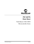
A.5
RN-XV-EK1 PHYSICAL DIMENSIONS
Figure A-7 shows the physical dimensions of the RN-XV-EK1 evaluation
board.
FIGURE A-7:
DS50002204A-page 36
RN-XV-EK1 PHYSICAL DIMENSIONS
2013 Microchip Technology Inc.
Worldwide Sales and Service
AMERICAS
ASIA/PACIFIC
ASIA/PACIFIC
EUROPE
Corporate Office
2355 West Chandler Blvd.
Chandler, AZ 85224-6199
Tel: 480-792-7200
Fax: 480-792-7277
Technical Support:
http://www.microchip.com/
support
Web Address:
www.microchip.com
Asia Pacific Office
Suites 3707-14, 37th Floor
Tower 6, The Gateway
Harbour City, Kowloon
Hong Kong
Tel: 852-2401-1200
Fax: 852-2401-3431
India - Bangalore
Tel: 91-80-3090-4444
Fax: 91-80-3090-4123
Austria - Wels
Tel: 43-7242-2244-39
Fax: 43-7242-2244-393
Denmark - Copenhagen
Tel: 45-4450-2828
Fax: 45-4485-2829
Atlanta
Duluth, GA
Tel: 678-957-9614
Fax: 678-957-1455
Austin, TX
Tel: 512-257-3370
Boston
Westborough, MA
Tel: 774-760-0087
Fax: 774-760-0088
Chicago
Itasca, IL
Tel: 630-285-0071
Fax: 630-285-0075
Cleveland
Independence, OH
Tel: 216-447-0464
Fax: 216-447-0643
Dallas
Addison, TX
Tel: 972-818-7423
Fax: 972-818-2924
Detroit
Novi, MI
Tel: 248-848-4000
Houston, TX
Tel: 281-894-5983
Indianapolis
Noblesville, IN
Tel: 317-773-8323
Fax: 317-773-5453
Los Angeles
Mission Viejo, CA
Tel: 949-462-9523
Fax: 949-462-9608
New York, NY
Tel: 631-435-6000
San Jose, CA
Tel: 408-735-9110
Canada - Toronto
Tel: 905-673-0699
Fax: 905-673-6509
DS50002204A-page 37
Australia - Sydney
Tel: 61-2-9868-6733
Fax: 61-2-9868-6755
China - Beijing
Tel: 86-10-8569-7000
Fax: 86-10-8528-2104
China - Chengdu
Tel: 86-28-8665-5511
Fax: 86-28-8665-7889
China - Chongqing
Tel: 86-23-8980-9588
Fax: 86-23-8980-9500
China - Hangzhou
Tel: 86-571-2819-3187
Fax: 86-571-2819-3189
China - Hong Kong SAR
Tel: 852-2943-5100
Fax: 852-2401-3431
China - Nanjing
Tel: 86-25-8473-2460
Fax: 86-25-8473-2470
China - Qingdao
Tel: 86-532-8502-7355
Fax: 86-532-8502-7205
China - Shanghai
Tel: 86-21-5407-5533
Fax: 86-21-5407-5066
China - Shenyang
Tel: 86-24-2334-2829
Fax: 86-24-2334-2393
China - Shenzhen
Tel: 86-755-8864-2200
Fax: 86-755-8203-1760
China - Wuhan
Tel: 86-27-5980-5300
Fax: 86-27-5980-5118
China - Xian
Tel: 86-29-8833-7252
Fax: 86-29-8833-7256
India - New Delhi
Tel: 91-11-4160-8631
Fax: 91-11-4160-8632
India - Pune
Tel: 91-20-3019-1500
Japan - Osaka
Tel: 81-6-6152-7160
Fax: 81-6-6152-9310
Japan - Tokyo
Tel: 81-3-6880- 3770
Fax: 81-3-6880-3771
Korea - Daegu
Tel: 82-53-744-4301
Fax: 82-53-744-4302
Korea - Seoul
Tel: 82-2-554-7200
Fax: 82-2-558-5932 or
82-2-558-5934
France - Paris
Tel: 33-1-69-53-63-20
Fax: 33-1-69-30-90-79
Germany - Dusseldorf
Tel: 49-2129-3766400
Germany - Munich
Tel: 49-89-627-144-0
Fax: 49-89-627-144-44
Germany - Pforzheim
Tel: 49-7231-424750
Italy - Milan
Tel: 39-0331-742611
Fax: 39-0331-466781
Italy - Venice
Tel: 39-049-7625286
Malaysia - Kuala Lumpur
Tel: 60-3-6201-9857
Fax: 60-3-6201-9859
Netherlands - Drunen
Tel: 31-416-690399
Fax: 31-416-690340
Malaysia - Penang
Tel: 60-4-227-8870
Fax: 60-4-227-4068
Poland - Warsaw
Tel: 48-22-3325737
Philippines - Manila
Tel: 63-2-634-9065
Fax: 63-2-634-9069
Singapore
Tel: 65-6334-8870
Fax: 65-6334-8850
Taiwan - Hsin Chu
Tel: 886-3-5778-366
Fax: 886-3-5770-955
Spain - Madrid
Tel: 34-91-708-08-90
Fax: 34-91-708-08-91
Sweden - Stockholm
Tel: 46-8-5090-4654
UK - Wokingham
Tel: 44-118-921-5800
Fax: 44-118-921-5820
Taiwan - Kaohsiung
Tel: 886-7-213-7830
Taiwan - Taipei
Tel: 886-2-2508-8600
Fax: 886-2-2508-0102
Thailand - Bangkok
Tel: 66-2-694-1351
Fax: 66-2-694-1350
China - Xiamen
Tel: 86-592-2388138
Fax: 86-592-2388130
China - Zhuhai
Tel: 86-756-3210040
Fax: 86-756-3210049
10/28/13
2013 Microchip Technology Inc.