1
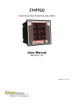
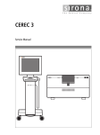
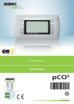
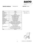
SCREW AIR COMPRESSOR CONTROLLER MAM6090 USER MANUAL Shenzhen Plot Electronic Co., Ltd Address:4-5F,5 Bldg,Highstar Industry Park,Gangtou Community, Bantian,Longgang District,Shenzhen City,China Telephone:(+86 0755)83173599 / 83172822 Postal code:518129 Fax:(+86 0755)83172966 E-mail:[email protected] Web site:www.pltsz.com VOTE OF THANKS Thank you for your trustworthy and select of PLOT air compressor controller ! Shenzhen Plot Electronic Co., Ltd specializes on the manufacture and R&D of air compressor controller. We are devoted to win customer trust through our high quality products and service. We try our best to ensure the completeness and correctness of the manual, but PLOT Company shall reserve the rights for continuous research and improvement on its products and assume no obligation for the modification and improvement on the previously delivered products. The design of products is subject to the change without notice. Please feel free to contact our after-sale service center if you encounter any problem with our product. You are always welcome to make suggestions and advice! Page 2 Total 43 NOTICE Please read all the operation manual before operating the set and keep this manual for further reference. Installation of MAM**** compressor controller can be performed only by professional technicians. Installation position shall be considered carefully in order to ensure good ventilation and reduce electromagnetic interference. Wiring shall be performed respectively according to regulations for heavy and weak current to reduce electromagnetic interference. RC snubber must be connected to the two terminals of coil (such as AC contactor ,valve, etc),which are controlled by relay output. Port connection shall be inspected carefully before power on. Correct ground connection (the third ground)can help increase product capacity of resisting signal interference. Set rated current of motor: the max current of motor/1.2. Features: ● ● ● ● ● ● ● ● Multiple run mode optional. 7 inch color screen ,with button and touch penal. Support real time power consumption and accumulative power consumption measurement. Scheduled on/off function and scheduled pressure function optional More accurate in writing frequency to control inverter through 485 communication Free to control all inverter supporting MODBUS RTU protocol. Open phase ,current overload ,current unbalance ,high voltage, low voltage protection for motor. High integration, high reliability, high cost performance Page 3 Total 43 Contents 1,Basic Operation ...................................................................................................................................................... 6 1.1 Button Explanation ...................................................................................................................................... 6 1.2 Indicator explanation ................................................................................................................................... 8 1.3, Status Display and Operation ..................................................................................................................... 8 1.4 Run Parameter ............................................................................................................................................. 9 1.5User Parameter ............................................................................................................................................11 1.6,Factory Parameter ...................................................................................................................................... 14 1.7,Calibration Parameter ................................................................................................................................ 16 1.8, Block Parameter........................................................................................................................................ 17 1.9,Hardware Parameter .................................................................................................................................. 18 1.10Maintenance Parameter ............................................................................................................................ 18 1.11 Inverter Set............................................................................................................................................... 19 1.12 Touch Calibration .................................................................................................................................... 21 1.13Scheduled P .............................................................................................................................................. 21 1.14 Scheduled On-Off.................................................................................................................................... 21 1.15 History Record......................................................................................................................................... 21 1.16 Motor VSD .............................................................................................................................................. 22 1.17 Fan VSD .................................................................................................................................................. 24 1.18 Date.......................................................................................................................................................... 26 1.19 Operation Authorization and Password ................................................................................................... 26 2,Controller Function and Technical Parameter ...................................................................................................... 27 3,Model and Specifixation....................................................................................................................................... 28 3.1 Model Explanation..................................................................................................................................... 28 3.2 Power Specification Sheet for Corresponding Motor. ............................................................................... 28 4,Installation ............................................................................................................................................................ 29 4.1 Mechanical Installation.............................................................................................................................. 29 4.2 Controller Installation................................................................................................................................ 29 5,Alarm function...................................................................................................................................................... 32 5.1,Air Filter Alarm ......................................................................................................................................... 32 5.2,Oil Filter Alarm.......................................................................................................................................... 32 5.3,O/A Separator Alarm ................................................................................................................................. 32 5.4,Lubricant Alarm......................................................................................................................................... 33 5.5,Grease Alarm ............................................................................................................................................. 33 5.6,Discharge High Temperature Alarm .......................................................................................................... 33 6,Controller Protection ............................................................................................................................................ 33 6.1 Motor Protection........................................................................................................................................ 33 6.2,Protection of Discharge Temperature High................................................................................................ 33 6.3,Protection of Air Compressor Anti-reversal .............................................................................................. 33 6.4, Protection of Air compressor Open Phase ................................................................................................ 34 6.5,Protection of Air Pressure High ................................................................................................................. 34 6.6,Protection of Sensor Fault ......................................................................................................................... 34 7,Trouble Shooting .................................................................................................................................................. 34 8, Block Control and Network Communication ...................................................................................................... 35 8.1 Block Control:......................................................................................................................................... 35 Page 4 Total 43 8.2 Network Communication........................................................................................................................... 36 9, Inverter Control ................................................................................................................................................... 36 10,Schematic Diagram............................................................................................................................................. 39 10.1PF.............................................................................................................................................................. 39 10.2PF /VSD.................................................................................................................................................... 40 10.3FAN VSD.................................................................................................................................................. 41 10.4MOTOR /FAN VSD ................................................................................................................................. 42 10.5SOFT START ........................................................................................................................................... 43 Page 5 Total 43 1,Basic Operation 1.1 Button Explanation Picture 1.1.1 Textbox Data set and display icon Page icon Page 6 Total 43 ——Start Button: When compressor is at stop status, press this button to start the compressor. When compressor is set as master ( No.1 ) in block status ,press this button to start the compressor and activate block mode function at the same time. ——Stop Button: When the compressor is at running status, press this button to stop the compressor; When compressor is set as master (No.1 ) in block status, press this button to stop compressor and block function as well; ——Set Button; Load / Unload Button: When the compressor is at running status ,press this button to load or unload ; When modifying data in textbox, press this button to save data and exist modification status When cursor is at any page icon, press this button to execute the corresponding function. ——Return Button / Reset Button: When the controller is at alarm and stop status, press this button for 5s to reset. When modifying data, press this button to exist data setting mode; When viewing the menu, press this button to return to previous menu; ——Move Left Button: When checking data in textbox, press this button to enter data modifying mode, data starts to blink from right to left . When modifying data in textbox, press this button to move the cursor to the left data When modifying data in data set and display icon, press this button to modify and save the data When cursor is in the page icon, press this data to move to the previous icon. ——Move Right Button/Enter Button: When checking data in textbox, press this button to enter data modifying mode, data starts to blink from left to right . When modifying data in textbox, press this button to move the cursor to the right data When modifying data in data set and display icon, press this button to modify and save the data When cursor is in the page icon, press this data to move to the next icon. ——Move Down Button / Decreasing Button: When checking the data, press this button to move downward the cursor to next icon; When modifying data in textbox, press this button to decrease the current data When the current page is at run parameter, press this button to swift to the next page ——Move Up Button/Increasing Button: When checking the data, press this button to move downward the cursor to precious icon; When modifying data in textbox, press this button to increase the current data Page 7 Total 43 When the current page is at run parameter, press this button to swift to the precious page 1.2 Indicator Explanation ——Power: Indicator is alight when controller is powered on ——Run: Indicator is alight when motor is running ——Alarm: Indicator is blinking when controller is alarming; Indicator is alight when compressor is alarm and stop; Indicator is off after error is cleared and reset. 1.3, Status Display and Operation The display screen will show as below after power on and display “MAM-6090”for a while: After 5 seconds, the menu will switch as below: This icon means scheduled on/off function is activated This icon means scheduled P function is activated This icon means auto restart function is activated This icon means remote function is activated This icon means block function is activated Press move left or move right button to execute corresponding function To prevent interference, it will take 0.2S to take effect ion after press start or stop icon This icon means computer Page 8 Total 43 User can enter the below menu through clicking MENU icons on the screen or press button” ” Blue means the cursor is now in this icon User can enter the corresponding menu through clicking these icons on the screen or press button”S” 1.4 Run Parameter Click“RUN PARAMETER”to check the relative data and set below Menu Preset Data Function STAGE 2 P 00.25MPa Display stage 2 pressure STAGE 2 T -0025℃ Display stage 2 temperature STAGE 1 P 00.00 MPa Display stage 1 pressure STAGE 1 T -0050℃ Display stage 1 temperature OIL FILTER 0020H Record total running time of oil filter. O/A SEPERATOR 0020H AIR FILTER 0020H Record total running time of air filter . LUBE 0020H Record total running time of lubricant. GREASE 0020H Record total running time of grease. SERIAL NO. 12345678 MOTOR CURRENT A:000.0A B:000.0A C:000.0A Display motor current FAN CURRENT A:000.0A B:000.0A C:000.0A Display fan current PRODUCTION DATE 2016-12-01 THIS RUN TIME 0000:00:00 Record total running time of O/A separator. Record compressor this run time Page 9 Total 43 THIS TIME LOAD 0000:00:00 Record compressor this load time SOFTWARE EDITION CK0135M0010 CHECK 0000 0000 INPUT STATE 1 2 3 4 5 6 7 8 9 10 ●●●●●●●●●● 1:In accordance with No.24 digital input state; 2:In accordance with No.23 digital input state; 3:In accordance with No.22digital input state; 4:In accordance with No.21 digital input state; 5:In accordance with No.20digital input state; 6:In accordance with No.19digital input state; Red circle of input state means terminal is connected; Orange circle of input state means terminal is disconnected OUTPUT STATE 1 2 3 4 5 6 7 8 9 10 ●●●●●●●●●● 1: In accordance with No.43 digital output state; 2: In accordance with No.42 digital output state; 3: In accordance with No.41 digital output state; 4: In accordance with No.40digital output state; 5: In accordance with No.39digital output state; 6: In accordance with No.37digital output state; Red circle of input state means terminal is connected; Orange circle of input state means terminal is disconnected MOTOR RATED SPEED 0000 RPM Display motor actual speed based on the calculation of frequency read MOTOR RATED POWER 000.0 Hz Display the output frequency of current motor inverter MOTOR OUTPUT CURRENT 000.0 A Display the output current of current motor inverter MOTOR OUTPUT VOLTAGE 000.0 V Display the output voltage of current motor inverter MOTOR OUTPUT POWER 000.0 Kw Display the real time output power of current motor inverter MOTOR THIS POWER CONSUMPTION 0000000.0Kw.H Display the accumulative this power consumption based on the motor inverter real time output power MOTOR TOTAL POWER CONSUMPTION 0000000.0Kw.H Display the accumulative total power consumption based on the motor inverter real time output power MOTOR STATE DISCRIPTION 0000 Display in the controller motor status area based on the running status register data reads from motor inverter Page 10 Total 43 motor ERROR DISCRIPTION 0000 Display in the controller error area based on the running error register data read from motor inverter WRITE FREQUENCY 000.0 Display the motor frequency based on PID calculation FAN SPEED 0000 RPM Display the fan real time speed based on the fan frequency read FAN OUTPUT FREQUENCY 000.0 Hz Display the output frequency of current fan inverter FAN OUTPUT CURRENT 000.0 A Display the output current of current fan inverter FAN OUTPUT VOLTAGE 000.0 V Display output voltage of current fan inverter FAN OUTPUT POWER 000.0 Kw Display the real time output power based on the current fan inverter. FAN THIS POWER CONSUMPTION 000000.00Kw.H Display the accumulative this power consumption based on the fan inverter real time output power FAN TOTAL POWER CONSUMPTION 000000.00Kw.H Display the accumulative total power consumption based on the fan inverter real time output power FAN STATE DISCRIPTION 0000 Display in the controller fan status area based on the running status register data reads from fan inverter ERROR DISCRIPTION 0000 Display in the controller error area based on the running error register data read from fan inverter WRITE FREQUENCY 000.0 Display the frequency based on the PID calculation PF MOTOR ØUI 000000.0Kw.H PF MOTOR THIS POWER CONSUMPTION 0000000.0Kw.H When set as PF, Display the compressor this time power consumption(FYI) PF MOTOR TOTAL POWER CONSUMPTION 0000000.0Kw.H When set as PF, Display the motor total power consumption(FYI) PF FAN ØUI PF FAN THIS POWER CONSUMPTION 000000.0 Kw.H 0000000.0Kw.H PF FAN TOTAL POWER 0000000.0Kw.H CONSUMPTION When set as FAN PF, Display the fan this time power consumption(FYI) When set as FAN consumption(FYI) PF, Display the fan total 1.5User Parameter User parameter is used to store relative data. User password is required for modification. Page 11 Total 43 power Touch operation:(base is yellow) 1, When the cursor is fixed here ,you can revise the parameter by clicking the data box directly if the password has been verified already 2, If the password is not verified yet, a password verification box will prompt .Button operation shows as below 1, In data checking mode, press left or right button to enter data modification mode; 2, In data checking mode, press up or down button to move the cursor to next icon; 3, In data modification mode, press up or down button to revise current data; 4, In data modification mode, press left or right button to move the cursor to next data bit When the cursor is in page icon, press “S” to execute corresponding function Main function is below: Menu Preset Data Function 00.65 1,In AUTO load mode , compressor will load if pressure is below this set data 2,In STANDBY mode, compressor will start if the pressure is below this set data UNLOAD P(MPa): 00.80 1,Compressor will unload automatically if air pressure is above this set data 2.This data should be set above LOAD P ,also should be set below UNLD P LIM FAN START T(℃): 0080 Fan will start if DISC T is above this set data FAN STOP T(℃): 0070 Fan will stop if DISC T is below this set data MOTOR START DELAY(S): 0008 Set the MOTOR START TIME. Record time when motor is activated, controller will not start overload protection during this time to avoid impulse starting current stopping the motor. 0003 Set the FAN START TIME. Record time when fan is activated, controller will not start overload protection during this time to avoid impulse starting current stopping the fan. LOAD P(MPa): FAN START DELAY(S): STAR DELAY(S): 0006 Interval time from star start to delta start. LOAD DELAY(S): 0002 Unloading in this set time after enter delta running STANDBY DELAY (S): 0600 When unloading continuously, compressor will automatically stop and enter to standby status if over this set time STOP DELAY(S): 0010 For NORMAL STOP operation, compressor will stop after it continuously unloads over this set time Page 12 Total 43 RESTART (S): DELAY 0100 Machine can start only over this set time at any case(after normal stop, standby or alarm &stop) DRAIN OPEN TIME(S): 0002 Auto drain control, continuously drain time DRAIN CLOSE TIME(M): 0060 Auto drain control, continuously drain interval time SOFT START DELAY(S): 0006 Controller starts LOAD DELAY TIME after SOFT-START DELAY (this data is only available in SOFT START mode) MANUAL/A UTOMATIC MANUAL : only when the pressure is above UNLD P, compressor will unload automatically .For any other case ,the Load/Unload function can only be executed by pressing “load/unload” key. AUTOMATICAL: the load/unload function can be executed by the fluctuation of AIR P automatically START MODE: LOCAL/RE MOTE LOCAL :only the button on the controller can turn on and turn off the machine. REMOTE: both the button on the controller and the remote control button can turn on and turn off the machine; Note: When one input terminal is set as REMOTE START ENABLE, start mode is controlled by hardware status. It is remote when terminal is close, it is local when terminal is open. In this case, the set here is not available. RUN MODE: PF/MOTOR VSD/FAN VSD/MOTO R FAN VSD/SOFT START Choose the corresponding compressor run mode according to customer requirement and choose the corresponding schematic diagram for reference. COM ADD: 0001 Set the communication address in COMPUTER or BLOCK mode. This address is unique for every controller in net BACKLIGHT ADJUSTMENT : 0001 Adjust the backlight, the higher the data, the brighter the display(from level 1 to level 4) COM MODE: COMPUTER /BLOCK/DIS ABLE DISABLE: communication function is not activated. COMPUTER: compressor can communicate with computer or DCS as slave according to MODBUS-RTU. Baud rate:9600;Data format:8N1;Parity bit: even parity check BLOCK: compressors can work in a net PRESSURE UNIT: MPa/PSI/BA R MPa: pressure unit displays as MPa PSI: pressure unit displays as PSI BAR: pressure unit displays as BAR TEMPERATURE UNIT: ℃/℉ ℃:temperature unit displays as ℃ ℉:temperature unit is displays as ℉ LANGUAGE: CHINESE/E NGLISH ENGLISH: Displays in English CHINESE: Displays in Chinese USER PASSWORD: **** User could modify the user password by old user password or factory password LOAD MODE: Page 13 Total 43 SLEEP BACKLIGHT 0007 Adjust the backlight when no operation in a long time 1.6,Factory Parameter Factory parameter is used to store relative data. Factory password is required for check and modification. The modification of factory parameter is same with customer parameter. Main function is below. Menu Preset Data Function MOTOR RATED CURRENT(A): Maximum motor overload data /1.2 When the current of motor is more than 1.2 times of the set data , the unit will stop for overload feature. (see table2.1.1) FAN RATED CURRENT(A): Maximum fan overload data/1.2 When the current of fan is more than 1.2 times than the set data , the unit will stop for overload feature. STAGE 1 ALARM T (℃): 0105 When stage 1 alarm temperature reaches this set data, compressor will alarm STAGE 2 STOP T ((℃): 0110 When stage 2 alarm temperature reaches this set data, compressor will alarm and stop STAGE 1 ALARM 0105 T When stage 1 alarm temperature is higher than this set data, compressor will alarm STAGE 2 STOP T 0115 When stage 2 stop temperature is higher than this set data, compressor will alarm and stop STAGE 2 STOP P (MPa): 00.90 When stage 2 stop pressure reaches this set data ,compressor will alarm and stop STAGE 1 STOP P (MPa):: 01.00 When stage 1 stop pressure is higher than this set data, compressor will alarm and stop UNLD P LIM(MPa): 00.85 This data is the maximum of UNLD P. The UNLD P in the customer parameter must be set no higher than this data. When MAX -MIN CURRENT >=(1+ SET DATA*MIN CURRENT/10 ),the unbalance protection is CURRENT UNBALANCE: 0006 OPEN PHASE PROT (S): 002.0 If OPEN PHASE protection ≥20 seconds, OPEN PHASE protection is not activated FAULT RESET: **** Input”8888”and press “set“ button to clear all the history fault record. ALARM LONG STOP 0000 (H): When controller detects oil filter,air filter, O/A separator lubricant and grease running over the max time and alarm over the data set, compressor will alarm and stop RECORD activated ,compressor will alarm and stop, reporting MOTOR CURR UNBAL If the set data ≥ 15, the unbalance protection will not be activated. Page 14 Total 43 MAX RUN (H): TIME 0000 1, When the compressor is in a stop status and the TOTAL RUN TIME is over this MAX TIME set, compressor will alarm and stop, reporting USER MISTAKE 2, Set the data to ‘0000’, this function is not activated. FACTORY PASSWORD 2: Set a FACTORY PASSWORD which can be modified. HIGH (V): 0410 When voltage is detected higher than HIGH VOLTAGE, the controller will alarm and stop When set as 0000, HIGH VOLTAGE protection function is not activated. LOW VOLTAGE(V): 0350 When voltage is detected lower than LOW VOLTAGE, the controller will alarm and stop When set as 0000, LOW VOLTAGE protection function is not activated. VSD COM OVERTIME(S): 002.0 Record time when controller sent first data, if controller failed to receive the feedback from inverter within this set time, controller is regarded overtime and will send command again. VSD COM INTERRUPT(S): 0020 If controller failed to receive feedback from inverter for this set time, VSD COM is interrupted. VSD RESTORE: 0015 After VSD COM is interrupted, and controller receives the correct data more than this set times, VSD COM is regarded restored. DISABLE/E NABLE ENABLE: SCHEDULED ON/OFF is valid DISABLE: SCHEDULED ON/OFF is invalid DISABLE/E NABLE ENABLE: S SET P SECTION is valid DISABLE: SET P SECTION is invalid TOTAL RUN TIME (H): 000100 H:00M Revise total run time TOTAL LOAD TIME (H) 000095 H:00M Revise total load time -0050 After power on,if the temperature is detected lower than the set data,it is not allowed to turn to.Two minutes after power on, if the temperature is detected lower than the set data,it is reported temperature sensor fault and stop. AUTO RESTART DISABLE/E NABLE Set the function of auto restart after power on again PF MOTOR POWER COEF 1.72 Set the coefficient for the calculation of motor power. MOTOR PF POWER CONSUMPTION (Kw.H) 0000000.0 Set and modify the motor power consumption in PF mode PF FAN COEF 1.72 Set the coefficient for the calculation of fan power. 000000.00 Set and modify the fan power consumption in PF mode VOLTAGE COM SCHEDULED ON/OFF: SET P SECTION LOW TEMP (℃) : PRO POWER FAN PF POWER CONSUMPTION (Kw.H) Page 15 Total 43 FREQ SELECT 50HZ Set the power frequency OIL PRES DIFF ALARM (MPa) 00.15 In loading mode,when air pressure and tank pressure are all above 0.5Mpa,and tank pressure-air pressure- line pressure resistance> oil pres diff alarm, controller will alarm OIL PRES DIFF STOP(MPa) 00.20 In loading mode,when air pressure and tank pressure are all above 0.5Mpa,and tank pressure-air pressure- line pressure resistance> oil pres diff stop, controller will stop REAR BEARING ALARM T(℃) 0000 When rear bearing stop temperature is above this set data, compressor will alarm REAR BEARING STOP T(℃) 0001 When rear bearing stop temperature is above this set data, compressor will alarm and stop LINE PRESSURE 00.05 RESISTANCE(MPa) line pressure resistance SERIAL NO. 12345678 Factory serial number PRODUCTION DATE 2015-01-01 Factory production date 1.7,Calibration Parameter Calibration parameter is used to store relative data. Calibration password is required for check and modification. Main function is below. Menu Preset Data MOTOR A COEF 1.000 MOTOR B COEF 1.000 MOTOR C COEF 1.000 FAN A COEF 1.000 FAN B COEF 1.000 FAN C COEF 1.000 T 1 COEF 1.000 T 2 COEF 1.000 T 3 COEF 1.000 T 4 COEF 1.000 T 5 COEF 1.000 T 6 COEF 1.000 Function Input the coefficient to calibrate current. Controller display current=sample current*coefficient. The range of coefficient: 0.800-2.000 Input the coefficient when calibrate discharge temperature. Controller display temperature=sample temperature*coefficient. The range of coefficient: 0.800-2.000 Note:this parameter is reserved in MAM6090 P 1 COEF 1.000 Input the coefficient to calibrate air pressure. Controller display pressure =sample pressure*coefficient. The range of coefficient:0.800-2.000 P 2 COEF 1.000 Note:this parameter is reserved in MAM6090 1.000 Input the coefficient to calibrate air pressure. Controller display pressure =sample pressure*coefficient. The range of coefficient:0.800-2.000 P COEF Page 16 Total 43 P1 RANGE(MPa) 0002 P2 RANGE(MPa) 0002 Calibrate controller temperature zero. Calibrate temperature to -20℃ when controller pressure sensor terminal connects the resistance in accordance with -20℃. For the calibration of temperature, it is required to calibrate T zero first and then calibrate coefficient T 1 ZERO 0002 T 2 ZERO 0002 T 3 ZERO 0002 T 4 ZERO 0002 T 5 ZERO 0002 T 6 ZERO 0002 P 1 ZERO 0002 When AIR P is below this set value, the pressure is displayed as 0.00.It is used to avoid air pressure transmitter from increasing. P 2 ZERO 0002 When P 2 is below this set value, the pressure is displayed as 0.00.It is used to avoid pressure zero from increasing. P1 RANGE P2 RANGE 0002 Note:this parameter is reserved in MAM6090 0002 PHASE PROT(V) 000.9 If the Three phase voltage is detected lower than the data set here, controller will report PHASE WRONG If PHASE PROT =0 second, PHASE PROT is not activated OPEN PHASE PROT(V) 000.0 If the open phase voltage is detected lower than the data set here,controller will report PHASE WRONG If OPEN PHASE protection =0 second, OPEN PHASE protection is not activated Note:this parameter is reserved in MAM6090 MOTOR RATIO 020 Motor rated current/5 001 Fan rated current /2.5 CURR FAN CURR RATIO STANDBY For manufacturer calibration 1.8, Block Parameter Block parameter is used to store relative data. Block password is required for check and modification. Main function is below. Menu Preset Data Function BLOCK NUMBER 0002 Number of air compressors in block net 00.63 In BLOCK mode, one compressor will start or load when master AIR P is below this set data 00.78 In BLOCK mode, one compressor will stop or unload when master AIR P is above this set data BLOCK DELAY(S) 0020 In BLOCK mode, when master sends two commands continuously, second command signal delays for this set data BLOCK (MPa) LOAD P BLOCK UNLOAD P (MPa) Page 17 Total 43 TURN TIME(M) 0060 When master pressure is between BLOCK LOAD P and BLOCK UNLD P, master determines slave to work alternatively after working over this set time BLOCK MODE PF-PF VSD-PF VSD-VSD PF-PF:PF compressor and PF compressor work in block mode VSD-PF: VSD compressor and PF compressor work in block mode VSD-VSD: VSD compressor and VSD compressor work in block mode 1.9,Hardware Parameter Hardware parameter is used to set the function from 17~24 31 32 33 terminals. Main function is below Menu Preset Data Function 24 TERMINAL: EMERGENCY 23 TERMINAL: / 22 TERMINAL: LACK WATER 21 TERMINAL: OIL FILTER 20 TERMINAL: O/A SEPERATOR 19 TERMINAL: AIR FILTER 18 TERMINAL: MULTIFUNCT IONAL 17 TERMINAL: REMOTE ON-OFF NO FUNCTION/EMERGENCY/REMOTE ON/REMOTE OFF/REMOTE INCHING/KEEP REMOTE / LACK WATER (N.C.)/REMOTE LOAD/REMOTE START ENABLE/REMOTE LOAD/UNLD /TANK HIGH T (N.C.)/ COIL HIGH T (N.C.)/ BEARING HIGH T (N.C.)/ ELEC FAULT (N.C.)/MOTOR OVLD (N.C.)/FAN OVLD (N.C.)/OIL BLOCK (N.C.)/ OIL BLOCK (N.O.)/ O/A BLOCK (N.C.)/O/A BLOCK (N.O.)/AIR FILTER BLOCK (N.C.)/AIR FILTER BLOCK (N.O.)/ AIR FAULT (N.C.)/DRYER FAULT (N.C.)/ MOTOR INV FAULT (N.O.)/ MOTOR INV FAULT (N.C.)/ FAN INV FAULT (N.O.)/ FAN INV FAULT (N.C.)。Note: User can set different digital input function 33 RELAY FUNCTION: RUN 32 RELAY FUNCTION: FAULT 31 RELAY FUNCTION: ALARM NO FUNCTION/ALARM/RUN/FAULT/READY/REMOTE/ START MOTOR INVERTER/START FAN INVERTER Note: User can set different relay output function 1.10Maintenance Parameter Maintenance parameter is used to store maintenance data. Maintenance password is required for check and modification. Main function is below. Menu Preset Data Function OIL FILTER RUN TIME(H) 0000 Record total running time of oil filter. If changing new oil filter, the data should be reset by manual operation. Page 18 Total 43 O/A SEPERATOR RUN TIME(H) 0000 Record total running time of O/A separator. If changing new O/A separator, the data should be reset by manual operation AIR FILTER RUN TIME(H) 0000 Record total running time of air filter .If changing new air filter, the data should be reset by manual operation LUBRICANT RUN TIME(H) 0000 Record total running time of lubricant. If changing new lubricant, the data should be reset by manual operation GREASE RUN TIME(H) 0000 Record total running time of grease. If changing new grease, the data should be reset by manual operation 2000 1, Alarm prompt when total running time of oil filter is above the set data . 2,Set this data to “0000” , alarm function for oil filter running time is not activated 2000 1, Alarm prompt when total running time of O/A separator is above the set data. 2,Set this data to “0000” ,alarm function for O/A separator running time is not activated 2000 1, Alarm prompt when total running time of air filter is above the set data. 2,Set this data to “0000” , alarm function for air filter running time is not activated 2000 1, Alarm prompt when total running time of lubricant is above the set data. 2, Set this data to “0000”, alarm function for lubricant running time is not activated. 2000 1, Alarm prompt when total running time of grease is above the set data. 2,Set this data to “0” , alarm function for grease running time is not activated OIL FILTER MAX RUN TIME(H) O/A SEPERATOR MAX RUN TIME(H) AIR FILTER MAX RUN TIME(H) LUBRICANT MAX RUN TIME(H) GREASE MAX RUN TIME(H) 1.11 Inverter Set Inverter set is used to set inverter data. Inverter password is required for check and modification. Main function is below.(The following chart is an example of Shneider inverter ATV61、ATV71 ) Menu INVERTER NAME: RUN(W) ADD1: Preset Data Function 0ATV61 Set inverter name, communicate any inverter supporting modbus 2135 Corresponding address 1 of inverter start command RUN VALUE: 0001 This data is inverter start data (please refer to communication chapter in inverter manual for different inverter.) RUN(W) ADD2: Corresponding address 2 of inverter start command 2135 RUN VALUE: 0001 This data is inverter start data (please refer to communication chapter in inverter manual for different inverter.) Page 19 Total 43 STOP(W) ADD: 2135 Corresponding address of inverter stop command RUN VALUE: 0001 This data is inverter start data (please refer to communication chapter in inverter manual for different inverter.) RESET(W) ADD: Corresponding address of inverter reset command 2135 RUN VALUE: 0001 This data is inverter start data (please refer to communication chapter in inverter manual for different inverter.) FREQ(W) ADD: 2136 Corresponding register address of inverter running frequency source FREQ(R) = REC*0001÷0001 The REC value is frequency value with one decimal. Use formula to transfer to corresponding value based on different inverter and send it to inverter. Example: 50HZ running frequency,REC value:500 For inverter with write frequency of 2 decimals, formula: REC**0001÷0010 For inverter with write frequency of 1 decimal, formula: REC**0001÷0001 For the inverter whose max output frequency is in corresponding with 10000,the formula :REC*0020÷0001 STATE(R) ADD: 2135 Read inverter running status address RUN S = R AND 0001=0001 Check if inverter has run the formula(please communication chapter in inverter manual) COM FORM 8N1-N Set the data format of controller and inverter communication. This set should be consistent with inverter communication format 8N1-N: 1start bit,8 data bits,1 stop bit, no parity bit 8N1-E: 1start bit,8 data bits,1 stop bit, even parity bit 8N1-O: 1start bit,8 data bits,1 stop bit, odd parity bit 8N2-N: 1start bit,8 data bits,2 stop bit, no parity bit Note: Communicate with inverter, the baud rate is fixed:9600 FREQ(R) ADD 0C82 Read inverter frequency address(refer to inverter manual ) FREQ(R) = REC*0001÷0001 Calculate inverter frequency formula. Controller will transfer the frequency to one decimal. VOLT(R) ADD 0C88 Read inverter voltage address VOLT(R) = REC*0001÷0001 Calculate inverter voltage formula. Controller will transfer the voltage to one decimal CURR(R) ADD 0C84 Read inverter current address CURR(R) = REC*0001÷0001 Calculate inverter current formula. Controller will transfer the current to one decimal POWE(R) ADD 0C8B Read inverter power address Page 20 Total 43 refer to POWE(R) REC*S*0001÷01 00 ERR ADD 6500 Read inverter error address ERR S = R AND 0000≠0000 Inverter reports error formula or not Calculate inverter power formula. Controller will transfer the power to one decimal EMERGENCY 2135 ADD Corresponding add of inverter emergency stop command RUN VALUE This data is inverter start data (please refer to communication chapter in inverter manual for different inverter.) 0001 1.12 Touch Calibration Touch calibration is used to adjust touch accuracy. Touch calibration password is required for adjustment. After entering touch calibration menu, use fingertip or other tool with sharp head to click A ,B ,C ,D in sequence. Press “S” button to restart and save the modification ; If user wants to calibrate again, press reset button and reset following precious step. 1.13Scheduled P Scheduled P is used to set scheduled pressure. Scheduled P password is required for check and modification. Main function is below. Menu Preset Data Function LOAD P(MPa): 00.65 During P START TIME and P STOP TIME, compressor will load if AIR P is below this set data UNLOAD P(MPa): 00.80 During P START TIME and P STOP TIME, compressor will unload if AIR P is above this set data 00.70 During P START TIME and P STOP TIME, set AIR P in VSD mode to keep running stable. When pressure is fluctuated around this data, controller will adjust operating frequency of inverter to control the pressure close to this data( This data is only available in MOTOR VSD or MOTOR/FAN VSD mode) P START TIME 00:00 Set this data to activate P SECTION SEL function. Set this data to “0”, this function is not activated P STOP TIME 00:00 Set this data to activate P SECTION SEL function. Set this data to “0”,this function is not activated SCHEDULED VSD P (MPa): 1.14 Scheduled On-Off Scheduled On-Off is used to set one week scheduled on-off time, four period is allowed to set in one day. Scheduled On-Off password is required for check and modification. Main function is below.When set to 00:00, the correspondent function is invalid. 1.15 History Record Record history fault for user to find causes and solutions.100 items are allowed to record. Page 21 Total 43 1.16 Motor VSD Motor VSD is used to set Motor VSD data. Motor VSD password is required for check and modification. Main function is below. Menu Preset Data Function VSD P(MPa) 00.70 Set AIR P in VSD mode to keep running stable. When pressure is fluctuated around this data, controller will adjust operating frequency of inverter to control the pressure close to this data( This data is only available in MOTOR VSD or MOTOR/FAN VSD mode) MOTOR UP SPEED 1000 Restrict PID calculations in case the frequency increasing too fast which cause motor speeding up too fast MOTOR DN SPEED 1000 Restrict PID calculations in case the frequency decreasing too fast which cause motor slowing down too fast 022.0 Set MOTOR RATED POWER in order to calculate actual power in VSD mode(This data is only available in MOTOR VSD or MOTOR/FAN VSD mode) 1500 Set MOTOR RATED SPEED at 50HZ in order to calculate the actual speed in VSD mode (This data is only available in MOTOR VSD or MOTOR/FAN VSD mode) 0020 When detected AIR P<(PID TARGET P -INTEGRAL SCALE) or Detected AIR P>(PID TARGET P +INTEGRAL SCALE) Integral calculation is based on this data MOTOR INT SCALE (Mpa) 00.20 (PID TARGET P - INTEGRAL SCALE)< detected AIR P < (PID TARGET P + INTEGRAL SCALE),INTEGRAL GAIN works MOTOR COEF 0.800 Coefficient to calculate motor power 0050 Track speed of PID TARGET P , the bigger the data, the faster the track; the smaller the data, the slower the track MOTOR RATED POWER(KW) MOTOR RATED SPEED(RPM) MOTOR INITIAL MOTOR GAIN INT POWER PROP Track the speed of PID TARGET P and STEADY STATE ERROR, the bigger the data ,the faster the track and smaller the MOTOR INT GAIN 0060 MOTOR DIFF GAIN 0000 Track the hysteresis system(such as temperature) ,it is not used very often and normally set as “0000” MOTOR MAX FREQ (HZ) 180.0HZ The maximum operating frequency in loading status MOTOR MIN FREQ (HZ) 040.0HZ In the process of adjustment, The minimum operating frequency when pressure is over the LOAD P pressure and not reach the UNLD P MOTOR FREQ(HZ) 0035.0HZ Permitted operating frequency in UNLD MODE UNLD STEADY-STATE ERRORS; the smaller the data ,the slower the track and bigger the STEADY-STATE ERRORS Page 22 Total 43 MOTOR INVERTER ADD 0001 Set the MOTOR VSD ADD and keep it consistent with VSD COM ADD MOTOR PID CYCLE (S) 000.8S Set the PID calculation interval time to adjust motor speed. MOTOR INVERTER MODEL ATV61 Controller can prestore at most 10 different inverter communication address ( Inverter should support MODBUS RTU protocol for communication ) SLOW/FREE 1、INVERTER START MODE to COM ON-OFF: SLOW:When controller receives stop command, INLET VALVE terminals will open。Controller sends stop command to inverter to slow stop inverter FREE:When controller receives stop command, INLET VALVE terminals will open。Controller sends write frequency through RS485.Controller frequency will decrease and send stop command to inverter 1S before stop delay finished. 2、INVERTER START MODE to TERMINAL ON-OFF: SLOW: When compressor receives stop command, INLET VALVE terminals will open and MOTOR INVERTER RUN terminal will open. The compressor will stop according to STOP DELAY set. FREE: When compressor receives stop command, Inlet valve will open. MOTOR INVERTER RUN terminal will keep closed to control inverter frequency decreasing and it will open until 1 S before STOP DELAY finishes COM / TERMINAL COM ON-OFF : Start or stop inverter through RS485 TERMINAL ON-OFF:Start or stop inverter through digital input Note: 1,Controller set should be accordance with INVERTER START MODE 2,When controller is set to PF/VF mode,terminal 12 functions as inverter control terminal so only COM ON-OFF is available to control inverter 0006 Maximum allowable time Controller sends start command to inverter with no response. 0006 Maximum allowable time Controller sends stop command to inverter with no response. VSD MOTOR POWER CONSUMPTION Kw.H 0000000.0 Set the accumulative motor VSD running power consumption. MOTOR INVERTER DELAY(S) 1.0 Press start button, motor sends start command to inverter after this set time. CONSTANT POWER PRESSURE 1(MPa) 0.60 In constant power running mode, when pressure is above the data set here, Max output frequency is set as CONSTANT POWER FREQUENCY1 MOTOR MODE STOP INVERTER MODE START INVERTER NO. START INVERTER NO. STOP Page 23 Total 43 CONSTANT POWER PRESSURE 2(MPa) 0.70 In constant power running mode, when pressure is above the data set here, Max output frequency is set as CONSTANT POWER FREQUENCY2 CONSTANT POWER PRESSURE 3(MPa) 0.80 In constant power running mode, when pressure is above the data set here, Max output frequency is set as CONSTANT POWER FREQUENCY3 0.90 In constant power running mode, when pressure is above the data set here, Max output frequency is set as CONSTANT POWER FREQUENCY4 1.00 In constant power running mode, when pressure is above the data set here, Max output frequency is set as CONSTANT POWER FREQUENCY5 1.10 In constant power running mode, when pressure is above the data set here, Max output frequency is set as CONSTANT POWER FREQUENCY6 1.20 In constant power running mode,when pressure is above the data set here, Max output frequency is set as CONSTANT POWER FREQUENCY7 CONSTANT POWER PRESSURE 4(MPa) CONSTANT POWER PRESSURE 5(MPa) CONSTANT POWER PRESSURE 6(MPa) CONSTANT POWER PRESSURE 7 (MPa) CONSTANT POWER FREQUENCY 1(HZ) 180.0 CONSTANT POWER FREQUENCY 2(HZ) 160.0 CONSTANT POWER FREQUENCY 3(HZ) 140.0 CONSTANT POWER FREQUENCY 4(HZ) 120.0 CONSTANT POWER FREQUENCY 5(HZ) 100.0 CONSTANT POWER FREQUENCY 6(HZ) 80.0 CONSTANT POWER FREQUENCY 7(HZ) 60.0 See Note1: Note 1:In constant power running mode CONSTANT POWER PRESSURE 1<= CONSTANT POWER PRESSURE 2<= CONSTANT POWER PRESSURE 3<= CONSTANT POWER PRESSURE 4<= CONSTANT POWER PRESSURE 5<= CONSTANT POWER PRESSURE 6<= CONSTANT POWER PRESSURE 7 Note 2:CONSTANT POWER FREQUENCY 1>= CONSTANT POWER FREQUENCY 2>= CONSTANT POWER FREQUENCY3>= CONSTANT POWER FREQUENCY 4>= CONSTANT POWER FREQUENCY 5>= CONSTANT POWER FREQUENCY 6>= CONSTANT POWER FREQUENCY 7 Note 3:Suppose M>N,When CONSTANT POWER PRESSURE N set to 00.00,CONSTANT POWER PRESSURE M and CONSTANT POWER FREQUENCY M,the set is invalid. Note 4: When constant power function is not required,set CONSTANT POWER PRESSURE to 00.00MPa 1.17 Fan VSD Fan VSD is used to set Fan VSD data. Fan VSD password is required for check and modification. Main Page 24 Total 43 function is below. Preset Data Function 0078℃ In VSD mode, set DISC T to keep running stable. When DISC T is fluctuated around this data, controller will adjust operating frequency of fan inverter to control DISC T close to this data( This data is only available in FAN VSD or MOTOR/FAN VSD mode) MAX VSD T(℃) 0085℃ When DISC T is above or equal to this data, control fan inverter output frequency to FAN MAX FREQ(This data is only available in FAN VSD or MOTOR/FAN VSD mode) FAN UP SPEED 1000 Restrict PID calculations in case the frequency increasing too fast which cause fan speeding up too fast FAN DN SPEED 1000 Restrict PID calculations in case the frequency decreasing too fast which cause fan slowing down too fast 001.5KW Set FAN RATED POWER to calculate the actual fan power in FAN VSD mode(This data is only available in FAN VSD or MOTOR/FAN VSD mode) 1500RPM Set the corresponding fan speed in 50HZ to calculate actual fan speed in FAN VSD mode((This data is only available in FAN VSD or MOTOR/FAN VSD mode) Menu FAN VSD T(℃) FAN RATED POWER FAN RATED SPEED VSD FAN START T(℃) 0070℃ VSD fan will start if DISC T is above this set data(This data is only available in FAN VSD or MOTOR/FAN VSD mode) VSD FAN STOP T(℃) 0065℃ VSD fan will stop if DISC T is below this set data(This data is only available in FAN VSD or MOTOR/FAN VSD mode) 0020 When detected DISC T< ( PID TARGET T -INTEGRAL SCALE)or Detected DISC T>(PID TARGET T +INTEGRAL SCALE) Integral calculation is based on this data 0005℃ (PID TARGET T - INTEGRAL SCALE)< detected DISC T < (PID TARGET T + INTEGRAL SCALE),INTEGRAL GAIN works. Beyond this range, INT INITIAL works. 0100 Track speed of PID TARGET T , the bigger the data, the faster the track and the less stable the data; the smaller the data the slower the track and the slower the adjustment FAN INT GAIN 0020 Track the speed of PID TARGET T and steady state error, the bigger the data ,the faster the track and smaller the steady-state errors; the smaller the data ,the slower the track and bigger the steady-state errors FAN DIFF GAIN 0000 Normally set as“0000”, this function is not activated FAN MAX FREQ(HZ) 050.0HZ In the process of adjustment, The maximum operating frequency when temperature is over the VSD work temperature FAN MIN FREQ(HZ) 010.0HZ In the process of adjustment, The minimum operating frequency when temperature is below the VSD work temperature FAN INT INITIAL FAN INT SCALE(℃) FAN PROP GAIN Page 25 Total 43 VSD COEF FAN POWER 0.900 Coefficient to calculate VSD fan power FAN INVERTER ADD 2 Set the FAN VSD ADD and keep it consistent with VSD COM ADD FAN PID CYCLE(S) 001.5S Set the PID calculation interval time to adjust fan speed. FAN MODEL ATV31 Choose inverter protocol COM/ TERMIN AL Set fan inverter start mode INVERTER FAN INVERTER START MODE VSD FAN ELEC(Kw.H) 000000.00 VSD fan power consumption 1.18 Date Check and set time 1.19 Operation Authorization and Password Controller provides multiple passwords and access management. According to different levels of passwords, controller provides different levels of operating authorization, details as following: 1.19.1 CUSTOMER PASSWORD:factory set: Permissions: Allows to modify all CUSTOMER PRAMETER. 1 9.2 FACTORY PASSWORD:fixed: Permissions: Allows to modify all CUSTOMER PRAMETER. Permissions: Allows to modify BASIC PARAMETER, MOTOR VSD PARAMETER, FAN VSD PARAMETER in FACTORY PARAMETER 1.19.3 CALIBRATE PASSWORD:fixed: Permissions: Allows to modify all CALIBRATE PARAMETER 1.19.4 BLOCK PASSWORD: Permissions: Allows to modify all BLOCK PARAMETER 1.19.5 HARDWARE CONFIG PASSWORD:fixed: Permissions: Allows to modify all HARDWARE CONFIG 1.19.6 MAINTENANCE PARAMETER PASSWORD Permissions: Allows to modify all MAINTENANCE PARAMETER. 1.19.7 INVERTER SET PASSWORD: Permissions: Allows to modify all INVERTER SET 1.19.8 TOUCH CALIBRATION PASSWORD Permissions: Allows to modify TOUCH ACCURACY 1.19.9 SCHEDULED P PASSWORD Page 26 Total 43 Permissions: Allows to modify all SCHEDULED P PARAMETER. 1.19.10 SCHEDULED ON/OFF PASSWORD Permissions: Allows to modify all SCHEDULED ON-OFF PARAMETER 1.19.11 MOTOR VSD PASSWORD: fixed: Permissions: Allows to modify all MOTOR VSD PARAMETER 1.19.12 FAN VSD PASSWORD: fixed: Permissions: Allows to modify all FAN VSD PARAMETER 2,Controller Function and Technical Parameter 2.1 Ambient temperature:-20℃~+60℃;Humidity:≤98%; 2.2 Digital input& output:8 points of digital input(function optional),10 points of digital relay output 2.3 Analog input& output:3 points of Pt100 temperature input。2 point 4-20mA pressure input,2 groups of three phases current input (CT provided) 2.4 Input voltage of phases: 380V/ 220V. 2.5 High voltage, low voltage protection. 2.6 Controller operation power supply:AC16-28V、20VA 2.7 Measurement : 2.7.1 DISC T:-50~350℃,Accuracy:±1℃。 2.7.2 Running time:0~999999H。 2.7.3 Current:0~999.9A。 2.7.4 Pressure:0~1.60MPa。Accuracy;0.01Mpa。 2.8 Phase anti-reversal protection: When compressor is at stop mode and detects phase reversal, response time≤ 1s 2.9 Motor protection: This controller provides open phase, unbalance and overload protection to motor, and also, provides overload protection to fan. 2.9.1, Open phase protection:When any phase opens, the response time equals to set time;This function is not activated when OPEN PHASE PROTECTION time is set over 20s 2.9.2, Unbalance protection: when MAX-MIN current >= SET DATA *MIN current/10 ,respond time is 5s; 2.9.3, Protection features of overload (time unit: second),please see following table(table 2.9.3.1)for your reference. Multiple=Iactual/Iset ,response time is shown in following table (table 2.9.3.1) according to overload multiples from 1.2 times and 3.0 times . Iactual/Iset Time parameter ≥1.2 ≥1.3 ≥1.5 ≥1.6 ≥2.0 ≥3.0 Response time(S) 60 48 24 8 5 1 Table 2.9.3.1 curve table for protection of motor 2.10 Temperature protection: when actual temperature measured is higher than temperature set; response Page 27 Total 43 time≤2s; 2.11 Contact capacity of output relay: 250V,5A;Contact endurance :500000 times 2.12 Current error is less than 1.0%.; 2.122 points of RS485communication port. 1 point is for block mode or computer communication. The other point is for inverter communication like reading inverter run parameter, controlling inverter on-off or adjusting inverter frequency. 2.14 Remote control compressor: When set as REMOTE, user can remotely control the compressor. 3,Model and Specifixation 3.1 Model explanation MAM 6090(B) (T) (V) (40) Motor max operating current Voltage detection and protection 485 communication function B: Pressure transmitter 6090 controller Model 3.2 Power specification sheet for corresponding motor. Current range (A) Corresponding main motor power (KW) MAM6090(20) 8~20 Below 11 MAM6090(40) 16~40 11-18.5 MAM6090(100) 100 22-45 MAM6090(200) 200 55-90 MAM6090(400) 400 110 600/5 200-250 Specification MAM6090(600/5) Remark Description With CT Fan has three levels of current, such as 0.2-2.5A, 1-5A and 4-10A, determined-by current of motor Table 3.2.1 Power specification sheet for corresponding motor Page 28 Total 43 4,Installation 4.1 Mechanical Installation The CT shall be installed at a place where the current of motor cable can be measured, thus, controller can be set according to instructions on motor nameplate, and the detailed dimension is shown as below: A B Picture 4.1.1, Structural dimension of CT1(ф36hole) Picture 4.1.2, Installation dimension of CT1 A B Picture 4.1.3, Structural dimension of CT2(ф10hole) Picture 4. 1.4, Installation dimension of CT2 4.2 Controller Installation When install the controller, room should be left around controller for wiring. The specific dimension is shown as below: Page 29 Total 43 Page 30 Total 43 4. 2.1 Controller structure dimension Page 31 Total 43 Picture 4.2.3 Hole size Note:Though rear cabinet is 220mm,the hole size should be at least 230mm.After connect the cable in the rear cabinet, there will be about 10-15mm more space requested. You can save the step of dispatch cable when install controller. 5,Alarm function 5.1,Air Filter Alarm ①. Air filter block check. (In HARDWARE CONFIG , there is air check function set in digital input terminal) The monitor displays AIR BLOCK by checking pressure differential switch close. ②. Air filter running time alarm The text displays AIR TIME END when running time of the air filter is exhausted. 5.2,Oil Filter Alarm ①. Oil filter block check. (In HARDWARE CONFIG, there is oil check function set in digital input terminal) The monitor displays OIL BLOCK by checking pressure differential switch close. ②. Oil filter running time alarm The text displays OILTIME END when running time of the oil filter is exhausted. 5.3,O/A Separator Alarm Page 32 Total 43 ①. O/A separator block check. (In HARDWARE CONFIG, there is O/A check function set in digital input terminal) The monitor displays O/A BLOCK by checking pressure differential switch close. ②. O/A filter running time alarm The text displays O/A TIME END when running time of the oil filter is exhausted. 5.4,Lubricant Alarm The text displays LUBE TIME END when running time of the lubricant is exhausted. 5.5,Grease Alarm The text displays GREASE TIME END when running time of the grease is exhausted. 5.6, Stage 2 Temperature High Alarm The text displays STAGE 2 T HIGH when DISC T is higher than STAGE 2 ALARM T set in FACTORY PARAMETER. 6,Controller Protection 6.1 Motor Protection MAM6090 compressor controller provides overload, open phase, unbalance, high voltage, low voltage protection to motor and overload protection to fan. Electronic failure Failure Display Reason Overload Display “:MOTOR/FAN CURR OVLD” Overload, bearing wear and other mechanical failure Open phase Display “MOTOR CUR OPEN PHASE” Power supply, contactor and open phase of motor Current Unbalance Display “MOTOR CURR UNBAL” Poor contact of contactor, inside open loop of motor High Voltage Display “HIGH VOLTAGE” Motor voltage high Low Voltage Display “LOW VOLTAGE” Motor voltage low 6.2,Protection of Discharge Temperature High When DISC T is above the STOP DISC T, the controller will alarm and stop the machine. THIS FAULT displays DISC T HIGH 6.3,Protection of Air Compressor Anti-reversal Page 33 Total 43 When compressor is at stop status and three phases sequence is not in order, THIS FAULT displays PHASE WRONG1, and the controller cannot start the motor. Change the position of any arbitrary two phase power lines and check the rotation of motor. 6.4, Protection of Air compressor Open Phase When compressor is at stop status and open phase is detected, THIS FAULT displays PHASE WRONG2, and the controller cannot start the compressor. Check the three phase. 6.5,Protection of Stage 2 P High When the Stage 2 P is above the MAX LIM P, the controller will alarm and stop the machine. THIS FAULT displays STAGE 2 P HIGH. 6.6,Protection of Sensor Fault When pressure sensor or temperature sensor is disconnected, the controller will alarm and stop the machine. THIS FAULT displays **SENSOR FAULT. 7,Trouble Shooting Failure Reason Solution High discharge temperature Bad vent condition, Oil shortage etc. Check the vent condition and lubricant amount etc. Temperature Sensor Failure Cable broken or PT100 failure Check the wiring and PT100 High Pressure Pressure too high or the pressure sensor failure Check the pressure and the pressure sensor Pressure Sensor Failure Cable broken, Sensor failure or the cables connect reversely Check the wiring and pressure transmitter Open Phase Power open phase or the contactor failure Check the power and contactors Overload Voltage too low, tubes block, bearing wear off or other mechanical failure or wrong set data etc. Check the set data, voltage, bearings, tubes and other mechanical system. Unbalance Current unbalance, contactor failure or the internal open loop of the motor Check the power, contactor and the motor Wrong Phase Sequence Phase sequence reversal or open phase Check the wiring Motor overload during start Master start time set to less than the star delta delay time Reset the master start time longer than star delay + 2 seconds Main Contactor shakes frequently The emergency stop button is loose or controller is reset by Check if the coil of contactor connects with RC snubber or not Page 34 Total 43 interference Inverter communication fault Wrong set of relatively parameter of controller and inverter; Communication cable loose Check the set data ;Check the cable 8, Block Control and Network Communication 8.1 Block Control: MAM6090 controller can work in block mode with MAM series compressor (with communication function).16 pieces compressors can work together in a net at most. Block mode can be set as VSD –VSD,PF-PF or VSD- PF .The cable connection for block mode control is as below....1,2 terminals ( RS485 terminal ) are used for block mode. In BLOCK PARAMETER SET menu, set as VSD-VSD or PF-PF,master chooses compressor to work according to the TOTAL RUN TIME. Compressor with shorter running time is chosen to start and compressor with longer running time is chosen to stop with priority. In BLOCK PARAMETER SET menu,, set as VSD-PF, master works first, other compressors work according to the TOTAL RUN TIME. Compressor with shorter running time is chosen to start and compressor with longer running time is chosen to stop with priority. No.1 No.2 No.3 No.4 No.N Pitcure8.1.1.1 Compressor with COM ADD 0001 is master, others are slave. Any one MAM series compressor can be set as master or slave. 8.1.1 Block Control Set: 8.1.2.1 Set as Master: Set rhe COM ADD in USER PARAMTER to 001 Page 35 Total 43 According to user requirement, set COM MODE, BLOCK NUMBER, TURN TIME, BLOCK LOAD P, BLOCK UNLD P, BLOCK DELAY , BLOCK MODE .After set, controller needs to be powered off and restart to save setting. 8.1.2.2 Set as Slave: When MAM6090 controller serves as slave, it is only necessary to set COM MODE as BLOCK, COM ADD can be set from2-16 in sequence according to the quantity of compressors, .BLOCK STATUS set as SLAVE. 8.1.2 Start, Stop Block mode: Make sure block cables connect correctly, also the parameter of compressor in block mode is set correctly. Activate master, master controls the compressor in net automatically according to the AIR P detected. When manually stop the master, block control stops at the same time, thus, master will no longer send command to compressors in net. 8.2 Network Communication MAM6090 controller supports MODBUS RTU protocol and can serve as slave when connects with other equipment .It is supports 03、06、16 MODBUS command. Communication baud rate: 9600BPS, 1 start bit, 8 data bits, 1 stop bits and even parity. For MODBUS register address, please see MODBUS communication manual. 9, Inverter Control 485 communication control There is one spare port for RS485 to communicate with inverter. User can start or stop controller through RS485,it transfers the output frequency based on PID calculation to inverter through 485 port. This is how to adjust inverter output frequency and realize constant pressure and temperature. The baud rate is fixed as 9600BPS when RS485 control inverter. Different inverter data format can be set in INVERTER SET in FACTORY PARAMETER. MOTOR INVERTER is suggested to be set as 0001, FAN INVERTER is suggested to be set as 0002. In order to be compatible with different inverter, set the item such as CURR(R) ADD, VOLT(R) ADD, FREQ(R) ADD , POWE(R) ADD, RUN (W) ADD, ERR STATE(R) ADD, FREQ(W) , RESET(W) ADD. For different inverter, amplification of current, voltage, frequency, power is different. Write a formula to every parameter to transfer current, voltage, frequency, power of inverter to one digit data. Relative parameter introduction is as below, please take the Schneider 67,71 inverter as example. Item INVERTER NAME: RUN(W) ADD1: Data Set Explanation 0ATV61 Set inverter name 2135 Corresponding address 1 of inverter start command RUN VALUE: 0001 This data is inverter start data (please refer to communication chapter in inverter manual for different inverter.) RUN(W) ADD2: Corresponding address 2 of inverter start command 2135 Page 36 Total 43 RUN VALUE: 0001 This data is inverter start data (please refer to communication chapter in inverter manual for different inverter.) STOP(W) ADD: Corresponding address of inverter stop command 2135 RUN VALUE: 0001 This data is inverter start data (please refer to communication chapter in inverter manual for different inverter.) RESET(W) ADD: Corresponding address of inverter reset command 2135 RUN VALUE: 0001 This data is inverter start data (please refer to communication chapter in inverter manual for different inverter.) FREQ(W) ADD: 2136 Corresponding register address of inverter running frequency source FREQ(R) = REC*0001÷0001 The REC value is frequency value with one decimal. Use formula to transfer to corresponding value based on different inverter and send it to inverter. Example: 50HZ running frequency,REC value:500 For inverter with write frequency of 2 decimals, formula: REC**0001÷0010 For inverter with write frequency of 1 decimal, formula: REC**0001÷0001 For the inverter whose max output frequency is in corresponding with 10000,the formula :REC*0020÷0001 STATE(R) ADD: 2135 Read inverter running status address RUN S = R AND 0001=0001 Check if inverter has run the formula(please communication chapter in inverter manual) COM FORM 8N1-N Set the data format of controller and inverter communication. This set should be consistent with inverter communication format 8N1-N: 1start bit,8 data bits,1 stop bit, no parity bit 8N1-E: 1start bit,8 data bits,1 stop bit, even parity bit 8N1-O: 1start bit,8 data bits,1 stop bit, odd parity bit 8N2-N: 1start bit,8 data bits,2 stop bit, no parity bit Note: Communicate with inverter, the baud rate is fixed:9600 FREQ(R) ADD 0C82 Read inverter frequency address(refer to inverter manual ) FREQ(R) = REC*0001÷0001 Calculate inverter frequency formula. Controller will transfer the frequency to one decimal. VOLT(R) ADD 0C88 Read inverter voltage address VOLT(R) = REC*0001÷0001 Calculate inverter voltage formula. Controller will transfer the voltage to one decimal CURR(R) ADD 0C84 Read inverter current address CURR(R) = REC*0001÷0001 Calculate inverter current formula. Controller will transfer the current to one decimal Page 37 Total 43 refer to POWE(R) ADD 0C8B Read inverter power address ERR S = R AND 0000≠0000 Inverter reports error formula or not EMERGENCY 2135 ADD Corresponding add of inverter emergency stop command RUN VALUE This data is inverter free stop data (please refer to communication chapter in inverter manual for different inverter.) 0001 Firstly,controller sends 0 to corresponding register of“STATE(R) ADD” through inverter. After delay for a while, sends 1 to corresponding register of“RUN1(W) ADD”. After another delay, reads“ RUN S”register, and judges if the inverter is running based on the set formula. Calculate the output frequency based on the comparison of pressure detected and pressure set and send this value to corresponding address of“FREQ(R) ADD” through formula operation. Schneidel inverter parameter set: 1、CON |AD2|AD1-|ADD :1 |EBr :96 |EFO :8N1 |EEO :15 CTL- | Fr1 :ndb |rln |PST |CHCF :IO |CD1 :ndb Flt- | PTC|rST- | rSF :C107 Page 38 Total 43 10, Schematic Diagram 10.1PF Page 39 Total 43 10.2PF /VSD 485 485485+ Note: If the inverter start mode is set as COM ON-OFF (start or stop inverter through RS485), please set the value of VSD COM OVERTIME to be 20 seconds (recommended)。The inverter will alarm and stop if it doesn't receive the data from the controller within this set time; Page 40 Total 43 10.3FAN VSD 接风机变频器485地线 接风机变频器485接风机变频器485+ Note: If the inverter start mode is set as COM ON-OFF (start or stop inverter through RS485), please set the value of VSD COM OVERTIME to be 20 seconds (recommended)。The inverter will alarm and stop if it doesn't receive the data from the controller within this set time; Page 41 Total 43 10.4MOTOR /FAN VSD 485 485485+ 485 485485+ Note: If the inverter start mode is set as COM ON-OFF (start or stop inverter through RS485), please set the value of VSD COM OVERTIME to be 20 seconds (recommended)。The inverter will alarm and stop if it doesn't receive the data from the controller within this set time; Page 42 Total 43 10.5SOFT START Page 43 Total 43