1
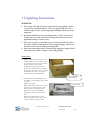
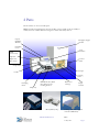
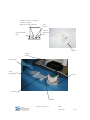
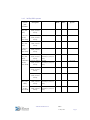
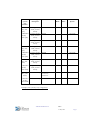
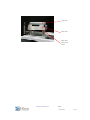
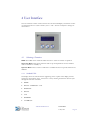
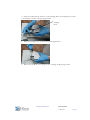
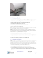
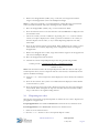
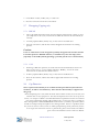
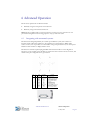
Fill-It User Manual (Mk V)
Stephen Guy
27 May 2010
TAP-9655-08-003Issue 1.2
Revision Record
Revision
Date
Author
Changes
Issue 1.00
25 Jan 2010
SRG
Created.
Issue 1.1
05 Mar 2010
PSG
Removed cap detect functionality from
Group N1 labware (Sarstedt)
Issue 1.2
27 May 2010
PSG
Updated tubeset loading instructions
Please follow these guidelines as you read the User Manual:
Warning:
Warnings must be followed carefully to
avoid operator injury.
Caution:
Cautions must be observed to avoid damage
to equipment.
Note:
Notes contain important information about
Fill-It and its operation.
GMP:
Specific instructions and helpful information
for GMP Users.
Glossary:
TAP
The Automation Partnership
GMP
Good Manufacturing Practice
IQ
Installation Qualification
OQ
Operational Qualification
TAP-9655-08-003 Issue 1.2
27 May 2010
Page ii
Contents
Contents
iii
1
Unpacking Instructions
1
2
Parts
3
2.1
Rack Nest Spacers for different tube types
5
2.1.1 96-Way Fill-It systems
2.1.2 24-Way Fill-It systems
3
4
5
5
6
Control Panel
9
3.1
9
Buttons/Indicators
User Interface
10
4.1
10
Selecting a Function
4.1.1 Standard Fill-It
4.1.2 GMP Fill-It (Operator mode)
10
11
4.1.3 Adjusting the settings for a function
4.1.4 Starting and Aborting a function
12
12
Basic Operation
13
5.1
13
Initial set up
5.1.1 Attaching the vacuum line (optional)
5.1.2 Attaching the AC power supply
5.2
5.3
13
14
Loading racks of tubes
14
5.2.1 For tube racks (e.g. 96-Way)
15
5.2.2 For TAP Racks (e.g. 24-Way)
Loading the Tube Set
15
15
5.3.1 Removing the Cradle
15
5.3.2 Loading the Tube Set into the Cradle
5.3.3 Unloading the Tube Set from the Cradle
5.3.4 Loading the Cradle
5.4
Priming the Tube Set
15
17
17
19
5.5
19
Calibrating the Tube Set
TAP-9655-08-003 Issue 1.2
Contents
27 May 2010
Page iii
6
7
5.6
Dispensing into tubes
20
5.7
Decapping/Capping only
21
5.7.1 DECAP
5.7.2 CAP 21
5.8
Cap Detection
21
21
5.9
De-priming the Tube Set
22
5.10
Maintaining the Tube Set when not in use
22
Advanced Operation
23
6.1
23
Integrating with automated systems
Maintenance
24
7.1
24
Cleaning and decontamination
7.1.1 General cleaning
7.1.2 More thorough cleaning
7.1.3 Decontamination
24
24
24
8
Disposal
25
9
Warranty
26
10
Troubleshooting
27
11
Contact Details
32
11.1
32
Support Office
TAP-9655-08-003 Issue 1.2
Contents
27 May 2010
Page iv
1 Unpacking Instructions
WARNING:
1. The weight of the Fill-It system is approximately 70 kg (155lb). Please
ensure that it is handled safely by at least two people with the aid of a
suitable trolley or hoist, and that appropriate lifting methods are always
employed.
2. Always lift the Fill-It system by holding its base. Failure to do so may
result in the heavy base of the unit becoming detached from its cover,
potentially leading to serious injury.
3. The centre of gravity of the Fill-It system is located towards one side of
the system and this is indicated on the external packaging. Please take
this into account when handling and lifting Fill-It.
4. Check that mounting brackets and bench tops required to support Fill-It
have been built to hold a weight of at least 70kg (155lb).
Instructions:
1. Inspect the ’tip and tell‘ feature on the
outside of the carton. If it indicates that
the carton has been incorrectly stacked
during transport, inform TAP
immediately and take special care to
inspect the enclosed items for damage.
If damage is observed, or if you have any
doubts about the safety or integrity of
the unit, inform TAP immediately.
Outer cardboard
side packaging
2. Carefully remove the banding around
the outside of the packaging with a knife
or scalpel.
Remove the top lid.
Before unpacking the main unit, remove
the inner box (containing tools, User
Manual, racks etc) from the carton.
Remove the outer cardboard side
packaging by lifting it cleanly off the
base.
Remove the retaining bolts on the
transport brackets (one on each side of
the unit) using the tools provided.
TAP-9655-08-003 Issue 1.2
Tools provided
Unpacking Instructions
27 May 2010
Page 1
3. With the aid of two or more people
and/or a suitable trolley or hoist,
carefully remove Fill-It from the carton.
Remove the outer polythene bag and
conduct a visual check for signs of
damage during transit.
Remove the transport brackets from
both sides of the unit using the Allen key
provided.
Remove the foam spacer from the Drip
Tray.
Inform TAP immediately if there is any
damage or loose items.
Retaining bolts one on each side
of Fill-It
4. If you need to relocate Fill-It or return it
to TAP for servicing or repair, you will
need to prepare it for transportation
using its original packaging. It’s
therefore advisable to store all packaging
supplied with the Fill-It system in a safe
place for at least one year.
5. Please read this User Manual before
operating Fill-It.
Transport
bracket - one
on each side of
Fill-It
Parts List:
The following items are supplied with a FillIt system. Please check that they are all
present when the unit has been unpacked.
1.
2.
3.
4.
5.
6.
7.
8.
Fill-It unit
Power cable
Rack (24-Way only)
Rack Nest
Rack Nest Spacer (s)
2 x Tube Sets
User Manual
Priming Tub (GMP version only)
TAP-9655-08-003 Issue 1.2
Foam spacer
ALWAYS LIFT THE UNIT BY
HOLDING ITS BASE - DO NOT
ATTEMPT TO LIFT THE UNIT
USING THE TRANSPORT BRACKETS
Unpacking Instructions
27 May 2010
Page 2
2 Parts
Fill-It contains no user serviceable parts.
Note: The following illustrations show the 96-Way version of Fill-It, but the 24-Way is
similar, the most notable difference being the 4 rather than 8-Way tube set.
Liquid
Handling
Module
Decapper/capper
module
Clamping
Lever
User
Interface
GMP
version only:
Operator Supervisor
Key switch
Control
Panel
Pump Head
AC Input
Cradle
Viewing
Panel
Rack, Rack Nest, Rack
Nest Spacer in the
Loading Position
Clamping
Hook
Rack Nest
Carriage
Finger
Guards
Drip Tray
Tube rack
Rack (24-Way only)
TAP-9655-08-003 Issue 1.2
Priming Tub (only supplied
with the GMP Fill-It)
Parts
27 May 2010
Page 3
Network connector – NOT for
customer use (TAP
diagnostic/servicing feature)
External Control
Port
Cycle
counter
Vacuum
Extraction
Port
Tube Set
Carriage
Guard
In-feed Tube
Tube
Spacing Bar
Cradle
Tube Set
Tip Block
TAP-9655-08-003 Issue 1.2
Parts
27 May 2010
Page 4
2.1
Rack Nest Spacers for different tube types
Rack Nest Spacers have been designed to support a wide range of different tube types and
the following table specifies the Rack Nest Spacer required for a given tube type. The table is
followed by an illustration showing how these are combined with Racks and Rack Nests:
2.1.1
96-Way Fill-It systems
TAP
system
part
number:
Tube type
description:
Cat No:
TAP
Rack:
Rack
Nest:
Rack Nest
Spacer:
Fill-It 96Way (0632F10)
Nunc 96-Way
0.5ml
374082
(025,026,027,066,06
7,074,075,083,086,0
87,097,099,100)
3
ü
063-0C50
Nunc 96-Way
1.0ml
374084
(070,078,079,085,08
9,088,090,094,110,1
20,130)
3
ü
063-0C05
Matrix 96-Way
0.5ml
3744(GRE,YEL,BL
U,RED,WHI,PUR)
3
ü
063-0C52
Matrix 96-Way
1.0ml
3741(GRE,YEL,BL
U,RED,WHI,PUR)
3
ü
063-0C06
Micronic 96-Way
0.5ml
MP52325-Z6,
MP52325LBCS-Z6
3
ü
063-0C07
Micronic 96-Way
1.1ml
MP52319-Z6,
MP52319LBCS-Z6
3
ü
063-0C07
FluidX 96-Way
0.5ml
65-52325-Z6-L
3
ü
063-0C07
FluidX 96-Way
1.1ml
65-52319-Z6-L
3
ü
063-0C07
GMP Fill-It
96-Way
(063-2F1B)
Fill-It 96Way (0632G10)
GMP Fill-It
96-Way
(063-2G1B)
Fill-It 96Way (0632H10)
GMP Fill-It
96-Way
(063-2H1B)
TAP-9655-08-003 Issue 1.2
Parts
27 May 2010
Page 5
2.1.2
24-Way Fill-It systems
TAP
system
part
number:
Tube type
description:
Cat No:
TAP
Rack:
Rack
Nest:
Rack Nest
Spacer:
Fill-It 24Way (0632F20)
Nunc 24-Way
1.8ml (external
thread)
347627, 375418
ü
ü
063-0C67
GMP Fill-It
24-Way
(063-2F2B)
Nunc 24-Way
4.5ml (external
thread)
347643, 337516
ü
ü
063-0C81
Fill-It 24Way (0632F30)
Nunc 24-Way
1.8ml (internal
thread)
377267
ü
ü
063-0C67
GMP Fill-It
24-Way
(063-2F3B)
Nunc 24-Way
4.5ml (internal
thread)
379146
ü
ü
063-0C84
Fill-It 24Way (0632K10)
Greiner 24-Way
2.0ml (external
thread)
126261,
126263(277,278,279
,280)
ü
ü
063-0C68
GMP Fill-It
24-Way
(063-2K1B)
Greiner 24-Way
3.5ml (external
thread)
127261,
127263(277,278,279
,280)
ü
ü
063-0C61
FluidX 24-Way
2.0ml (external
thread)
65-7501
ü
ü
063-0C68
FluidX 24-Way
3.5ml (external
thread)
65-7511
ü
ü
063-0C61
Fill-It 24Way (0632K20)
Greiner 24-Way
1.0ml (internal
thread)
123261,
123263(277,278,279
,280)
ü
ü
063-0C80
GMP Fill-It
24-Way
(063-2K2B)
Greiner 24-Way
2.0ml (internal
thread)
122261,
122263(277,278,279
,280)
ü
ü
063-0C82
TAP-9655-08-003 Issue 1.2
Parts
27 May 2010
Page 6
TAP
system
part
number:
Tube type
description:
Cat No:
TAP
Rack:
Rack
Nest:
Rack Nest
Spacer:
Fill-It 24Way (0632J10)
Corning 24-Way
5.0ml (external
thread)
430663
ü
ü
063-0C84
GMP Fill-It
24-Way
(063-2J1B)
Corning 24-Way
4.0ml (external
thread)
430662
ü
ü
063-0C62
Corning 24-Way
2.0ml (external
thread)
430659
ü
ü
063-0C66
Fill-It 24Way (0632J20)
Corning 24-Way
1.2ml (internal
thread)
430487
ü
ü
063-0C69
GMP Fill-It
24-Way
(063-2J2B)
Corning 24-Way
2.0ml (internal
thread)
430488
ü
ü
063-0C66
Fill-It 24Way (0632L10)
Nalgene 24-Way
1.0ml (external
thread)
5000-1012
ü
ü
063-0C65
GMP Fill-It
24-Way
(063-2L1B)
Nalgene 24-Way
1.5ml (external
thread)
5000-1020
ü
ü
063-0C64
Fill-It 24Way (0632N10)
Sarstedt 24-Way
72.730.xxx,
72.703.xxx
72.692.xxx
ü
ü
063-0C83
GMP Fill-It
24-Way
(063-2N1B)
Sarstedt 24-Way
72.694.xxx
ü
ü
063-0C63
Example: Nunc (96-Way 1ml) configuration
TAP-9655-08-003 Issue 1.2
Parts
27 May 2010
Page 7
Tube rack
Rack Nest
Rack Nest
Spacer 0630C05
TAP-9655-08-003 Issue 1.2
Parts
27 May 2010
Page 8
3 Control Panel
The Control Panel consists of ‘GO’, ‘STOP’, and ‘RESET’ buttons, and these are used to
control the operation of Fill-It.
3.1
Buttons/Indicators
Buttons/Indicators:
Function:
1
‘GO’ Button and Indicator
Initiates a user defined
Function (see following
section on the User
Interface)
2
‘RESET’ Button and
Indicator
Press to reset Fill-It to a
known condition
3
‘STOP’ Button and Indicator
Press to halt the operation of
Fill-It
TAP-9655-08-003 Issue 1.2
Control Panel
27 May 2010
Page 9
4 User Interface
The user interface consists of three buttons and a 20 X 4 LCD display. The buttons consist
of a Function button to select a function, and ‘+’ and ‘–‘ buttons to adjust the settings for
that function.
4.1
Selecting a Function
GMP: The GMP version of Fill-It enables the User to select two modes of operation:
Supervisor Mode: where all the functions and set-up mode parameters for the standard
version of Fill-It are available, or,
Operator Mode: where a subset of functions is available and the set-up mode functions are
disabled.
4.1.1
Standard Fill-It
The display shows the current function (appearing on the top line of the display) and the
settings for that function (if any, on lines two to four). Pressing the Function button cycles
through the functions as follows:
•
PRIME
•
DECAP – DISPENSE – CAP
•
DISPENSE
•
DECAP
•
CAP
•
DEPRIME
•
CALIBRATE
TAP-9655-08-003 Issue 1.2
User Interface
27 May 2010
Page 10
Holding the Function down for 3 seconds switches the function menu into set-up mode.
Pressing the Function button while in set-up mode cycles through the set-up options and
holding down the Function button for 3 seconds returns the function menu to normal
operation. The set-up option always appears on the top line of the display and is surrounded
by *s and the settings for that option are shown on lines two to four. The set-up options are
as follows:
•
*DISPENSE SPEED*
•
*SUCKBACK VOLUME*
•
*SUCKBACK SPEED*
•
*DISPENSE POSITION*
•
*TEACH VIAL DETECT*
•
*TEST VIAL DETECT*
•
*RESET DEFAULTS*
•
*VERSION*
•
*SELF TEST*
•
*TORQUE TEST MODE*
4.1.2
GMP Fill-It (Operator mode)
The display shows the current function (appearing on the top line of the display) and the
settings for that function (if any, on lines two to four). Pressing the Function button cycles
through the functions as follows:
•
PRIME
•
DECAP – DISPENSE – CAP
•
DEPRIME
Holding the Function down for 3 seconds switches the function menu into set-up mode.
Pressing the Function button while in set-up mode cycles through the set-up options and
holding down the Function button for 3 seconds returns the function menu to normal
operation. The set-up option always appears on the top line of the display and is surrounded
by *s and the settings for that option are shown on lines two to four. The set-up options are
as follows:
•
*VERSION*
TAP-9655-08-003 Issue 1.2
User Interface
27 May 2010
Page 11
4.1.3
Adjusting the settings for a function
Once a function has been selected, any settings for that function will be displayed with the
corresponding units for that setting. Using the ‘+’ and ‘–‘ buttons, the value for the setting
may be adjusted within the valid range for the setting. Holding the ‘+’ or ‘–‘ button down for
more than 2 seconds will increase or decrease the value ten time faster. The user should
adjust the setting before initiating the function.
4.1.4
Starting and Aborting a function
All functions with the exception of ‘PRIME’ and ‘DEPRIME’ are started or aborted with a
momentary press of the ‘GO’ and the ‘STOP’ buttons respectively (see section on the
Control Panel).
TAP-9655-08-003 Issue 1.2
User Interface
27 May 2010
Page 12
5 Basic Operation
GMP: GMP Users are encouraged to read the following sections to gain familiarity with the
basic operation of the Fill-It system, before proceeding with the specific instructions given in
the supplied IQ and OQ documentation.
5.1
Initial set up
Unpack Fill-It, as described in the Unpacking Instructions, and use the following procedures
to set up the machine prior to use.
It is highly unlikely that there will be any issues with the set-up and operation of Fill-It. If
there are any difficulties, please refer to the Troubleshooting section of this manual. If you
experience further difficulties, please request assistance from TAP at the address given in the
Contact Details section of this Manual.
Fill-It features a Cycle Counter, which counts every time a capping cycle is completed. When
you receive your Fill-It, the Cycle Counter will already display a number of counts. These are
due to Cycles run during quality control testing. If you contact TAP concerning a problem
with the Fill-It, you may be asked to provide the number displayed on the counter.
You may also be asked to remove the glass Viewing Panel to gain access to the rack within
the decapping/recapping module. To remove it, turn the knurled fasteners and detach. To
replace, refasten, and check that it is secure.
Note: Fill-It will not function without the Viewing Panel in place.
5.1.1
Attaching the vacuum line (optional)
To reduce airborne particulates and evapourate in the vicinity of the open tubes, thereby
reducing the chance of contamination, Fill-It features a 19mm outer diameter port that can
TAP-9655-08-003 Issue 1.2
Basic Operation
27 May 2010
Page 13
be connected to a suitable (e.g. for outputting biological vapours) vacuum-based extraction
system.
Note: Attaching a vacuum line is NOT necessary for successful operation of Fill-It, but may
be a useful in some applications. Please note that suitable vacuum hosing and a pump are not
supplied with the standard Fill-It system.
1. Locate the extraction port on the side of Fill-It
2. Attach suitable flexible hosing to the port and connect this to the external extraction
system (typically 1 bar of negative pressure is sufficient)
3. Turn the external extraction system ON.
5.1.2
Attaching the AC power supply
1. Check that the AC power cable supplied with Fill-It is the one specified at the time of
order. Plug the cable into the side of Fill-It and into your AC outlet. Fill-It contains a
universal power supply so there is no need to adjust any voltage settings.
2. Switch Fill-It ‘ON’ using the power switch above the AC inlet on the side of the unit.
The power-up sequence can take up to one minute to ‘boot-up’.
3. The screen on the User Interface will light up, and after a short period it will display:
“FAULT – Push RESET to use machine”
4. Ensuring there is nothing in the way of the Rack Nest Carriage, press the ‘RESET’
button. The mandrels in the Decapper/capper module will rise, and the Rack Nest
Carriage will move into the Decapper/capper module, then move out again to the rack
loading position.
5.2
Loading racks of tubes
Fill-It is configured for a given set of tubes that are specified at the time of order.
Caution:
The type of tube used affects the performance of Fill-It. Using incorrect tubes
may cause damage. Please ensure that you always use the correct tubes for
the current configuration of Fill-It.
Vendors supply tubes in a variety of different working volumes and sizes. To accommodate
these, Fill-It is supplied with a variety of Racks (24-Way only), Rack Nests, and Rack Nest
Spacers to convert Fill-It for use with the range of tubes specified at the time of order.
To configure these items correctly:
1. Identify the manufacturer; tube catalogue number, volume, and external or internal
thread configuration, of the tubes that are to be used.
2. Using the table and illustration given in Section 2.1, identify the correct configuration of
Rack (24-Way only), Rack Nest, and Rack Nest Spacer to be used, and assemble them as
indicated. The Rack Nest Spacer should be placed onto the Rack Nest Carriage followed
by the Rack Nest, and Rack (24-Way only).
TAP-9655-08-003 Issue 1.2
Basic Operation
27 May 2010
Page 14
Note: Once the correct Rack (24-Way only), Rack Nest, and Rack Nest Spacer are
assembled into Fill-It, subsequent tubes (24-Way only), or tube racks, can be loaded and
unloaded without further re-assembly of these items.
3. Load the system with tubes as follows:
5.2.1
For tube racks (e.g. 96-Way)
Place the tube rack into the Rack Nest ensuring that there is a good fit, and that the rack sits
horizontally in the nest. When loading the rack, ensure that it is in the correct orientation (i.e.
column 1 is on the left, column 12 on the right). If it’s not, the rack will not sit properly in
the Rack Nest, and will fail to be decapped or capped properly.
5.2.2
For TAP Racks (e.g. 24-Way)
Load the tubes by hand into the mounting holes in the Rack.
Note: When loading tubes by hand into the Rack, please ensure that they are seated
correctly, as failure to do so may cause Fill-It to enter a fault condition. To prevent this,
carefully rotate each of the tubes until the anti-rotation feature on the base of the tube
locates with the holes in the base of the Rack.
5.3
Loading the Tube Set
Fill-It combines a ‘peristaltic’ pump with a disposable Tube Set for precise aliquotting of cell
cultures and other liquids into the open tubes. Liquid is extracted from a suitable vessel (e.g.
spinner flask), supplied by the user, at the ‘in-feed’ end of the Tube Set and dispensed into
the tubes at the other.
Fill-It is designed to operate within a suitable HEPA filtered enclosure (e.g. standard
biological Class II safety cabinet) and the following steps should be conducted within this
environment.
5.3.1
1.
Removing the Cradle
Lower the Clamping Lever. Fill-It will go into Fault (if it’s turned ‘ON’)
1. Carefully, push the Rack Nest Carriage to the right, so that it’s out of the way.
2. While holding the Cradle up towards the Pump Head, swing out the Clamping Hook
and then let the Cradle swing down.
3. Unhook the right hand side of the Cradle. It’s now free of Fill-It.
5.3.2
Loading the Tube Set into the Cradle
1. Remove the outer packaging from the Tube Set
2. Make sure the Clamping Screw is loosened (you may have to undo the Locking ring
first)
TAP-9655-08-003 Issue 1.2
Basic Operation
27 May 2010
Page 15
Locking ring
Clamping
screw
3. Push the Tip Block into the grooves in the bottom of the Cradle, as shown below:
Note: The Tip Block is supplied with a cover that should be kept in place during
loading.
4. Holding the Cradle in one hand, the correct way up, grasp the 8 (or 4) branched tubes
firmly and gently stretch them till the rear block clicks into place, as shown below. Do
not pull on the Y connectors or the single feed tube, as this may damage the Tube Set.
TAP-9655-08-003 Issue 1.2
Basic Operation
27 May 2010
Page 16
5. Ensure that the Tip Block and the Tube Spacing Bar are fully located in their respective
grooves in the cradle
6. Gently tighten the Clamping Screw (a light pressure is required only). Then gently
tighten the Locking Ring
5.3.3
Unloading the Tube Set from the Cradle
After use, the Tube Set is removed from the Cradle as follows (refer to photos in section
5.3.2:
1. Loosen the Locking Ring; then loosen the Clamping Screw
2. Holding the Cradle in one hand, the correct way up, grasp the 8 (or 4) branched tubes
firmly and gently stretch them till the rear block comes free from the Cradle groove.
3. Now the tension has been removed from the Tube Set, it can be easily removed from
the Cradle.
5.3.4
Loading the Cradle
1. Hook the right hand side of the Cradle on the Pump Head, as shown in the photograph
below:
TAP-9655-08-003 Issue 1.2
Basic Operation
27 May 2010
Page 17
2. Swing the Cradle upwards, and hook on the Clamping Hook (the Clamping Lever needs
to be lowered), as shown in the photograph below:
Clamping
Hook
3.
Raise the Clamping Lever, as shown in the photograph below:
4. Remove the Tip Block cover taking care not to damage the dispensing nozzles.
TAP-9655-08-003 Issue 1.2
Basic Operation
27 May 2010
Page 18
5.4
Priming the Tube Set
1. Place the vessel containing the liquid to be dispensed (e.g. a spinner flask) close to Fill-it
(ideally in-line with the Pump Head). Remove and discard the outer bag from the ‘infeed’ end of the Tube Set, and place the tube within, or connect it to, the vessel.
2. Remove the Rack (24-Way only) or tube rack from the Rack Nest.
3. Re-apply power to Fill-It (turn the system ‘ON’)
4. Reset Fill-It by pressing the Reset button on the front panel.
5. Place a collection vessel in the Rack Nest.
Note: A collection vessel is not supplied with the standard Fill-It system, but as an example,
an overturned 96-Way tube rack lid can be used for this purpose.
GMP: The GMP version of Fill-It is supplied with a stainless steel Priming Tub that has
been specifically been designed to reduce the likelihood of splashing and is autoclavable. If
required, this item can be purchased separately, on request.
6. Select the ‘PRIME’ function from the User Interface function menu.
7. Press and hold the ‘GO’ button, and continue until all the nozzles are dispensing evenly,
and you are satisfied that the tubes are full and clear of bubbles, at which point release
the ‘GO’ button.
8. Safely remove and empty the collection vessel or Priming Tub.
5.5
Calibrating the Tube Set
GMP: The GMP version of Fill-It is supplied with analysis spreadsheets to complete the IQ
and OQ procedures satisfactorily. When using these, users must ensure that 'Automatic
Calculation' is selected from the ‘Options’ menu within Microsoft Excel. Additionally, these
spreadsheets are only approved for use on Microsoft Excel 97 SR-2 or Microsoft Excel 2003.
1. Perform a re-set by pressing the Control Panel ‘RESET’ button.
2. Place a populated Rack (24-Way only) or tube rack in the Rack Nest.
3. Select ‘DECAP’ from the User Interface menu, and press the Control Panel ‘GO’
button. Fill-It will remove the caps from the tubes and return them to the original input
position.
TAP-9655-08-003 Issue 1.2
Basic Operation
27 May 2010
Page 19
4. Remove the decapped Rack (24-Way only) or tube rack, and weigh and record the
weight of the decapped rack. This is the PreDispense Weight.
Note: To achieve this aseptically, it’s recommended that suitable laboratory measurement
scales are installed within the same Class II biological safety cabinet as Fill-It.
5. Place the decapped Rack (24-Way only) or tube rack back into Fill-It.
6. Press the Function button on the User Interface until ‘CALIBRATE’ is displayed on the
User Interface menu.
7. Choose the volume you wish to calibrate to by pressing the ‘+’ or ‘-‘ buttons until the
volume you require is displayed. It’s usually a good idea to calibrate to the volume you
intend to dispense into the tubes, i.e. if you will be dispensing 500µl into each tube,
select 500µl.
8. Press the ‘GO’ button from the Control Panel. Fill-It will dispense the volume you have
selected either 96 or 24 times (depending on the configuration) before returning the
decapped rack.
9. Remove the decapped rack of tubes, weigh and record the weight of the de-capped rack.
This is the PostDispense Weight.
10. Place the decapped rack back into Fill-It
11. Calculate the volume of liquid dispensed per tube using the following formula:
Volume per tube = (PostDispense Weight) – (PreDispense Weight)
Number of tubes
Note: This calculation assumes that the liquid dispensed is dH20 as it relies on 1ml=1g. If
another liquid is chosen, then it is important that the correct density is determined, and the
equation modified accordingly.
12. Using the ‘+’ or ‘-‘ buttons adjust the volume displayed so that it matches the calculated
volume.
13. Press the ‘GO’ button. The system is now calibrated and the displayed volume defaults
to that selected in (7) above.
14. Press the Function button until ‘CAP’ is displayed, and press the ‘GO’ button from the
Control Panel. Fill-It will replace the caps onto the tubes and return the Rack (24-Way
only) or tube rack to the original Loading Position.
5.6
Dispensing into tubes
Selecting the correct mode of operation depends on whether the user wants to dispense into
precapped or uncapped tubes:
For precapped tubes: select ‘DECAP-DISPENSE-CAP’ from the User Interface menu.
For uncapped tubes: select ‘DISPENSE’ from the User Interface menu.
1. Select one of the functions above:
2. Press the ‘+’ or ‘–‘ buttons to choose the required dispense volume.
TAP-9655-08-003 Issue 1.2
Basic Operation
27 May 2010
Page 20
3. Load a Rack of tubes (24-Way only) or a tube rack.
4. Press the ‘GO’ button from the Control Panel.
5.7
Decapping/Capping only
5.7.1
DECAP
1.
Choose the ‘DECAP’ function from the User Interface function menu (unless you have
just completed a ‘CAP’ cycle, in which case the ‘DECAP’ function will automatically be
selected).
2.
Load the populated Rack (24-Way only) or tube rack into the Rack Nest.
3.
Press the ‘GO’ button, and the tubes will be decapped and returned to the loading
position.
Caution:
Users are advised not to load uncapped or partially uncapped racks of tubes into FillIt and then perform a ‘DECAP’ function, as mandrels may enter the empty tubes
(especially on the 24-Way Fill-It) providing a potential path for cross contamination)
5.7.2
CAP
1. Following a ‘DECAP’ operation, the ‘CAP’ function will automatically be selected. If
this is not the case (e.g. you are capping following a ‘RESET’), choose the ‘CAP’
function from the User Interface function menu.
2. Load the populated Rack (24-Way only) or tube rack into the Rack Nest.
3. Press the ‘GO’ button, and the tubes will be capped and returned to the loading
position.
5.8
Cap Detection
Note: cap detect functionality is not available for Group N1 labware (Sarstedt tubes
72.703.xxx, 72.730.xxx and 72.694.xxx). Tube detection functionality is supported for
this group.
Before dispensing into a rack, Fill-It will check which columns of tubes are in the rack, and
whether there are any caps present. The tube and cap detection sensors are set up in the
factory. On receipt of a Fill-It is recommended that the Cap Detection feature is tested and
this can be performed by loading a Rack (24-Way only) or tube rack, with 1-2 columns of
tubes missing. When a ‘DECAP-DISPENSE-CAP’ function (or similar) is performed, Fill-It
should not attempt to dispense liquid into the missing columns. If there is a problem (which
may occur if it receives a heavy knock, or similar, perhaps during transit), Fill-It may need to
be re-taught. For instructions on how to perform this, please contact TAP at the address
given in the Contact Details section of this User Manual.
TAP-9655-08-003 Issue 1.2
Basic Operation
27 May 2010
Page 21
5.9
De-priming the Tube Set
De-priming the Tube Set enables:
•
Valuable liquid to be recovered in the source vessel
•
Avoids liquid dribbling from the nozzles when the Tube Set clamping is released (see
below)
To de-prime the Tube Set:
1. Select the ‘DEPRIME’ function from the User Interface function menu.
2. Press and hold the ‘GO’ button, until all the liquid is recovered into the source vessel.
5.10 Maintaining the Tube Set when not in use
In common with all other peristaltic pumps used for precision dispensing, the Tube Set
should not be left under tension when it is not being used, as its accuracy will be significantly
impaired. When clamped for extended periods of time, the silicone tubing takes on a "set"
which does not recover fully when the pump is used again.
To maintain the Tube Set in optimum condition when not in use:
•
De-prime the Tube Set (see above)
•
Release the Clamping Lever
Note: The Tube Set does not need to be removed from its Cradle
TAP-9655-08-003 Issue 1.2
Basic Operation
27 May 2010
Page 22
6 Advanced Operation
Fill-It can be operated in two distinct modes:
•
Manually using the front panel control buttons
•
Remotely using an External Control Port
Note: Fill-It is supplied with a network connector, but this is not for customer use. It is
provided for diagnostic and servicing purposes only, by staff from TAP.
6.1
Integrating with automated systems
Fill-It has been designed primarily as a bench top standalone system, but contains an
External Control Port that enables it to be interfaced to external devices. While under
remote control, it is not possible to control Fill-It using front panel buttons, but front panel
Indicators will continue to display Fill-It’s status.
Fill-It has an external 15 pin D-plug (labelled ‘External Control Port’ on the diagram in
Section 2) on the outside of the machine for connection with external volt free contacts, and
details of the pin configurations are given below:
D-Pin
No.
1
2
3
4
5
6
7
8
9
10
11
12
13
14
15
Pin
Name
RRRRRO
RO
RO
n/c
R+
R+
R+
R+
RC
RC
RC
Signal
Function
Input 1
Input 2
Input 3
Input 4
Output 1
Output 2
Output 3
n/a
Input 1
Input 2
Input 3
Input 4
Output 1
Output 2
Output 3
Signal Name
Description
Go
Prime
Reset
External Control
Ready
Busy
Fault
n/a
Go
Prime
Reset
External Control
Ready
Busy
Fault
0Vdc signal to ‘Go’ Relay
0Vdc signal to ‘Prime’ Relay
0Vdc signal to ‘Reset’ Relay
0Vdc signal to ‘External Control’ Relay
Volt-free contact from ‘Ready’ Relay
Volt-free contact from ‘Busy Relay
Volt-free contact from ‘Fault Relay
Not connected
24Vdc signal to ‘Go’ Relay
24Vdc signal to ‘Prime’ Relay
24Vdc signal to ‘Reset’ Relay
24Vdc signal to ‘External Control’ Relay
Volt-free contact from ‘Ready’ Relay
Volt-free contact from ‘Busy Relay
Volt-free contact from ‘Fault Relay
TAP-9655-08-003 Issue 1.2
Advanced Operation
27 May 2010
Page 23
7 Maintenance
GMP: GMP Users are encouraged to read the instructions below to gain familiarity with the
basic cleaning of the Fill-It system, before following the specific instructions given in the
associated Fill-It cleaning and contamination protocol document.
7.1
Cleaning and decontamination
7.1.1
General cleaning
The outer surfaces of Fill-It can be cleaned with typical laboratory cleaning agents and 70%
alcohol/water solutions. Fill-It may be used with samples containing DMSO as a
cryopreservative.
7.1.2
More thorough cleaning
For more thorough cleaning, the Rack (24-Way only), Rack Nest, Rack Nest Spacer, Rack
Nest Carriage, and Drip Tray can all be removed and cleaned separately. The glass Viewing
Panel on the Decapper/recapper module can also be removed for access to internals (e.g.
mandrels) that can be lightly sprayed with typical laboratory cleaning agents and dried with a
sterile cloth.
To disassemble Fill-It for cleaning:
1. Remove the Rack (24-Way only), Rack Nest, and Rack Nest Spacer by lifting off the
Rack Nest Carriage.
2. The Rack Nest Carriage can then be lifted out of the machine (when replacing, ensure
that the pins are fully engaged)
3. Pull the Drip Tray forward horizontally away from Fill-It
4. The Cradle can be removed as described in section 5.3.1
5. The Decapper/recapper glass Viewing Panel can be removed by unscrewing the 4
fasteners on the front of the panel. The fasteners will remain captive in the panel.
Note: None of the components are autoclave safe.
7.1.3
Decontamination
Fill-It is tolerant to specific decontamination regimes based on hydrogen peroxide, typically
that offered by Bioquell Inc.
Warning:
Users must not decontaminate Fill-It with formaldehyde (or similarly harsh
chemicals) as these can cause permanent damage to electrical circuitry.
TAP-9655-08-003 Issue 1.2
Maintenance
27 May 2010
Page 24
8 Disposal
The disposal of Fill-It is the responsibility of the customer and must be disposed of in an
environmentally responsible manner.
TAP-9655-08-003 Issue 1.2
Disposal
27 May 2010
Page 25
9 Warranty
12 months warranty packages are provided for the standard Fill-It and GMP version of FillIt. Enhanced Service and Support packages above that provided as standard are available on
request from TAP.
TAP-9655-08-003 Issue 1.2
Warranty
27 May 2010
Page 26
10 Troubleshooting
Fill-It has been designed to provide trouble-free operation, but the following is provided to
help diagnose and solve any problems that may occur during its life.
Note: The following is designed for troubleshooting Fill-It when it’s being used as a
standalone unit. It does NOT offer solutions to problems that arise when Fill-It is under
external control or integrated into an automated system.
Symptom:
Cause:
Solution:
The display is showing
“Fault – Push Reset to use
Machine”, but pressing
‘RESET’ does nothing.
This may have happened
because (a) the Cradle is not
present with the Clamping
Lever up (the Tube Set does
not have to be in), or (b) the
glass Viewing Panel is not
present, or is not attached
correctly.
Load the Cradle and/or
replace the Viewing Panel.
Press the ‘RESET’ button.
Fill-It should reset. Note:
Removing and/or replacing
the Viewing Panel with the
power still ‘ON’ may cause
Fill-It it to go into a Safety
Fault condition. This is not
dangerous. If this occurs,
once the panel is fully
replaced, turn the power
‘OFF’, wait 10 seconds, and
turn it back on again. Press
the ‘RESET’ button when
prompted.
The ‘GO’, ‘RESET’ and
‘STOP’ lights are flashing
and the display is saying
“Safety Fault – Fault
Detected with Pump
Guard”.
This may have happened for
3 reasons:
Turn the power to Fill-It
‘OFF’, ensure that the Cradle
is correctly installed and that
the Clamping Lever is fully
raised, and turn the power to
Fill-It back ‘ON’. If it’s still
in the Safety Fault condition,
then one of the safety microswitches has failed, and the
Fill-It will need to be
serviced before it can be
used again.
1. The Cradle is incorrectly
fitted
2. The Clamping Lever was
raised to slowly or not
fully
3. One or more of the
safety micro-switches
has failed (in which case
Fill-It is in a safe state,
and has detected the
failure and is preventing
further operation until
rectified).
TAP-9655-08-003 Issue 1.2
Troubleshooting
27 May 2010
Page 27
Symptom:
Cause:
Solution:
The ‘GO’, ‘RESET’ and
‘STOP’ lights are flashing
and the display is saying
“Safety Fault – Fault
Detected with Front Cover
Guard”.
Either:
Turn ‘OFF’ the power to
Fill-It. Ensure that the glass
Viewing Panel is correctly
installed (i.e. all four fixings
are fully located and
tightened, and the panel is
flush). Turn ‘ON’ the power
to Fill-It. If it’s still in the
Safety Fault condition, then
one of the safety microswitches has failed, and the
Fill-It will need to be
serviced before it can be
used again.
(a) The glass Viewing Panel
was removed and
replaced with the power
to the machine still ‘ON’
(b) One of the safety microswitches has failed.
The ‘GO’, ‘RESET’ and
‘STOP’ lights are flashing
and the display is saying
“Safety Fault – Fault
Detected with Stage Guard”.
Either:
(a) The Rack Nest Carriage
and/or the Drip Tray is
not correctly installed
(b) There’s an obstruction
in the decapper/capper
module section of the
Drip Tray
(c) One of the safety microswitches has failed.
Turn ‘OFF’ power to Fill-It.
Remove the Rack (24-Way
only), Rack Nest, Rack Nest
Spacer, and Rack Nest
Carriage. Remove, clean and
replace the Drip Tray,
ensuring that it is fully
located (i.e. level with the
Fill-It base and parallel to the
front of Fill-It). Replace the
Rack Nest Carriage, ensuring
that the supporting pins are
pushed fully home, such that
the Rack Nest Carriage is
fully seated in the Drip Tray
and is parallel to the front of
Fill-It.
Turn ‘ON’ the power to FillIt. If it’s still in the Safety
Fault condition, then one of
the safety micro-switches has
failed, and Fill-It will need to
be serviced before it can be
used again.
TAP-9655-08-003 Issue 1.2
Troubleshooting
27 May 2010
Page 28
Symptom:
Cause:
Solution:
The ‘GO’, ‘RESET’ and
‘STOP’ lights are flashing
and the display is saying
“Safety Fault – Fault
Detected with Finger
Guard”.
Either:
Turn ‘OFF’ power to Fill-It.
Remove any obstruction
above the Carriage Guard if
it’s positioned within the
Decapper/capper Module.
Turn ‘ON’ power to Fill-It,
and press the ‘RESET’
button when prompted. If
it’s still in the Safety Fault
condition, then one of the
Finger Guards has failed,
and Fill-It will need to be
serviced before it can be
used again.
(a) There was an
obstruction above the
Carriage Guard whilst it
was in the
Decapper/capper
Module (such as a
finger)
(b) One of the Finger
Guards has failed.
Note: The Finger Guards
are ‘through the beam’ light
sensors.
The ‘GO’, ‘RESET’ and
‘STOP’ lights are flashing
and the display is saying
“Safety Fault – Fault
Detected with Main Safety
Relay”.
The Main Safety Relay
within Fill-It may have failed.
This is not dangerous, as
Fill-It will have detected the
fault and will prevent further
use until fixed.
TAP-9655-08-003 Issue 1.2
Turn ‘OFF’ power to Fill-It,
wait 10 seconds, and then
turn it back ‘ON’. If it’s still
in the Safety Fault condition,
then Fill-It will require
servicing before it can be
used again.
Troubleshooting
27 May 2010
Page 29
Symptom:
Cause:
Solution:
Upon capping, Fill-It has
stopped, and the readout is
displaying “Fault”.
Fill-It may have failed to
fully tighten a cap, and it is
sitting proud of the other
caps.
Press the ‘RESET button.
The rack will be lifted clear
of the Rack Nest, and the
Rack Nest will move away to
the Loading Position. At
this point you can either:
(a) Remove the Viewing
Panel, and manually
remove the rack from
the mandrels by pulling
it downward
Attempt another cap. To do
this, set Fill-It to ‘DECAP’
and press ‘GO’. Watch the
rack carefully. If it goes into
the Rack Nest without any
problems, then Fill-It will
decap the rack, after which
you can cap it. If the rack
doesn’t go straight into the
Rack Nest, press the ‘STOP’
button immediately,
otherwise there is a risk of
damaging the rack and the
samples. Press the ‘RESET’
button, and once Fill-It has
reset (lifting the rack clear of
the Rack Nest), remove the
Viewing Panel and recover
the rack manually.
TAP-9655-08-003 Issue 1.2
Troubleshooting
27 May 2010
Page 30
Symptom:
Cause:
Solution:
Following decapping or
capping, the Rack Nest
Carriage is jammed within
the Decapper/capper
Module.
A cap may have fallen off
and jammed the mechanism,
or a mandrel may have been
pulled off and is still in the
rack.
Turn ‘OFF’ power to Fill-It.
Remove the Viewing Panel,
and recover the rack
manually (the Rack Nest
Carriage can be moved by
hand when the machine is in
a Fault condition). If a
mandrel has been pulled
down, push it back up until
it clicks back in (it may need
to be rotated).
Fill-It is not tightening the
caps tight enough.
Fill-It uses individual
clutches to ensure that each
cap is tightened to the
correct torque, as specified
by the labware
manufacturers. These
clutches gradually wear with
time. If your Fill-It has
decapped and capped over
7000 racks (to see how many
racks have been through the
Fill-It, see the Cycle
Counter), TAP cannot
guarantee that the tightening
torque will be in the
specified range.
If your Fill-It has decapped
and capped more than 7000
racks, it will need to be
refurbished or replaced.
Please contact TAP.
TAP-9655-08-003 Issue 1.2
Troubleshooting
27 May 2010
Page 31
11 Contact Details
11.1 Support Office
The Automation Partnership (Cambridge) Ltd.
York Way
Royston
Herts.
SG8 5WY
United Kingdom
Telephone: +44 (0) 1763 227 333
Fax: +44 (0) 1763 227 201
Email: [email protected]
TAP-9655-08-003 Issue 1.2
Contact Details
27 May 2010
Page 32