1
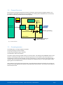
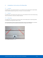
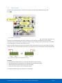
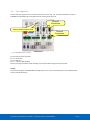
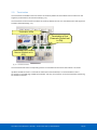
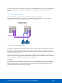
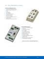
2.4
Power Supply
The two 2-pin screw type power connectors are located on the left of the ProfiHub B2+ (Fig. 10).
1 = + (left)
2 = - (right)
Power LEDs
Alarm contact
Power
Connectors
Grounding points
Fig. 10 - Power connectors and LEDs
Both power connectors are linked 1-on-1 to the internal power supply of the B2+. If one power supply fails, the
other takes over without delay time. When redundancy is not required, it is sufficient to use one power
connector. Please note that when using only one power supply, a voltage of max. 0.25 V will exist on the other
unconnected power connector, like shown in Fig. 11.
If only one power supply is used, the alarm contact is closed. If two power sources are connected, the contact
is open. As soon as one of the power supplies fails, the contact will close and the Power Indicator LED will blink.
Fig. 11 – Maximum voltage on unconnected Power Connector
Procedure
To connect the 24V supply to the 2-pin screw-type terminal, proceed as follows:
• Strip the insulation from the cable or the conductors for the 24V power supply.
• Add cable crimp terminals/wire ferrules to the conductors.
• Secure the crimp terminals in the screw-type terminal.
To connect the power supply, you need a 3 mm screwdriver.
User Manual ProfiHub B2+ / B2+RD | 24 december 2014 | ©PROCENTEC
14/55