1
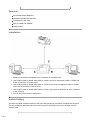
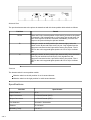
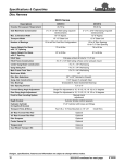
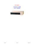
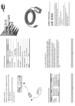
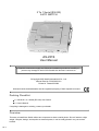
2 To 1 Serial (RS-232)
AUTO SWITCH
AS-251S
User Manual
Read this manual thoroughly and follow the installation procedures carefully to
prevent any damage to the AS-251S and/or the devices it connects to.
©Copyright 2000 Aten® International Co., Ltd.
Manual Part No. PPAG-905-001
Printed in Taiwan 05/2002
All brand names and trademarks are the registered property of their respective owners.
Packing Checklist
1 x AS-251S 2 to 1 Serial (RS-232) Auto Switch
1 x User's Manual
If anything is damaged or missing, contact your dealer.
Overview
This easy to install Auto Switch allows two computers to share a serial printer. Since it features a light
weight, compact, design, and requires no external power, it can be easily placed in any convenient
location.
1 of 4
Features
No External Power Required
Automatic and Manual Selection
Transparent to the User
Easy to Install and Operate
Compact size
Installation
1. Make sure that all the equipment to be connected up is powered Off.
2. Use a DB-25 male to female serial cable to connect your first computer's COM1 or COM2 port
to the A connector of the AS-251S.
3. Use a DB-25 male to female serial cable to connect your second computer's COM1 or COM2
port to the B connector of the AS-251S.
4. Use a DB-25 male to female serial cable to connect your printer's serial port to the C connector
of the AS-251S.
5. Turn on the power to all the equipment.
Switch Setting
There are two slide switches located on the unit's side panel that are used to configure the AS-251S.
The one on the left determines which port has access to the printer; the one on the right sets the
timeout value.
2 of 4
Selected Port
The port that has access to the printer is determined with this three position slide switch as follows:
Position
Result
AUTO
Under AUTO (the central position of the switch), access to the printer
is automatic, and is determined on a first come first served basis. As
soon as a signal is received, the switch immediatley connects and
stays on the port until the print job has finished.
B
Sliding the switch to the B position (the extreme right), locks the
switch on the B port and locks out the A port. Only signals from the
computer connected to the B port will be sent to the printer. The B
LED on the unit's top panel lights (and the A LED is off) to indicate
this.
A
Sliding the switch to the A position (the extreme left), locks the switch
on the A port and locks out the B port. Only signals from the
computer connected to the A port will be sent to the printer. The A
LED on the unit's top panel lights (and the B LED is off) to indicate
this.
Timeout
The timeout switch is a two position switch:
Slide the switch to the left position for a 10 second timeout.
Slide the switch to the right position for a 60 second timeout.
Specifications
Function
3 of 4
Specification
Cable Distance
15 m
Input Connectors
2 x DB-25 Female (DCE)
Output Connectors
1 x DB-25 Female (DTE)
Port Selection
Automatic / Selectable
Timeout
10 / 60 secs.
Operating Temp.
5 to 40˚ C
Storage Temp.
-20 to -60˚ C
Humidity
0 - 80% RH
Housing
Plastic
Weight
130 g
Dimensions (L x W x H)
105 x 85 x 26 mm
Limited Warranty
IN NO EVENT SHALL THE DIRECT VENDOR S LIABILITY EXCEED THE PRICE PAID FOR THE
PRODUCT FORM DIRECT, INDIRECT, SPECIAL, INCIDENTAL, OR CONSEQUENTIAL
DAMAGES RESULTING FROM THE USE OF THE PRODUCT, DISK, OR ITS DOCUMENTATION.
The direct vendor makes no warranty or representation, expressed, implied, or statutory with respect
to the contents or use of this documentation, and specially disclaims its quality, performance,
merchantability, or fitness for any particular purpose.
The direct vendor also reserves the right to revise or update device or documentation without
obligation to notify any individual or entity of such revisions, or update. For further inquires please
contact your direct vendor.
4 of 4