1
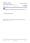
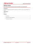
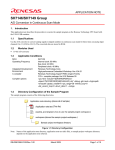
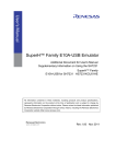
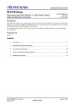
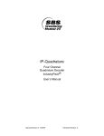
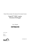
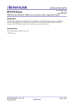
APPLICATION NOTE
SH7216/SH7239/SH7231 Groups
Data Transfer Within On-Chip RAM (Cycle Stealing Mode)
Using the DMAC
R01AN1262EJ0100
Rev.1.00
Dec. 07, 2012
Abstract
This application note describes a sample program for the SH7216, SH7239, and SH7231 Group MCUs that transfers
data using the direct memory access controller (DMAC).
The operation of this program has the following features.
•
•
•
•
Use of DMAC channel 0
Use of auto-request mode for DMA transfers
Use of cycle stealing mode as the bus mode
The transfer source and destination are both in RAM.
Products
SH7216, SH7239, and SH7231 Groups
When using this application note with other Renesas MCUs, careful evaluation is recommended after making
modifications to comply with the alternate MCU.
R01AN1262EJ0100 Rev.1.00
Dec. 07, 2012
Page 1 of 16
SH7216/SH7239/SH7231 Groups
Data Transfer Within On-Chip RAM (Cycle Stealing Mode) Using the DMAC
Contents
1.
Specifications ..................................................................................................................................... 3
2.
Operation Confirmation Conditions .................................................................................................... 4
3.
Reference Application Notes .............................................................................................................. 5
4.
Peripheral Functions........................................................................................................................... 6
5.
Software ............................................................................................................................................. 8
5.1 Operation Overview ..................................................................................................................... 8
5.2 File Composition .......................................................................................................................... 9
5.3 Constants ..................................................................................................................................... 9
5.4 Functions...................................................................................................................................... 9
5.5 Function Specifications .............................................................................................................. 10
5.6 Flowcharts.................................................................................................................................. 12
5.6.1 Main Processing ................................................................................................................. 12
5.6.2 Transfer Source/Transfer Destination Memory Area Initialization...................................... 13
5.6.3 DMAC Initialization ............................................................................................................. 14
5.6.4 DMA Transfer Start Processing .......................................................................................... 15
5.6.5 DMA Transfer End Processing ........................................................................................... 15
6.
Reference Documents...................................................................................................................... 16
R01AN1262EJ0100 Rev.1.00
Dec. 07, 2012
Page 2 of 16
SH7216/SH7239/SH7231 Groups
1.
Data Transfer Within On-Chip RAM (Cycle Stealing Mode) Using the DMAC
Specifications
This application note uses the direct memory access controller (DMAC) to transfer data within internal RAM.
The sample program sets the DMAC to cycle stealing mode and uses auto-request as the DMA transfer start factor. The
sample program performs 128 transfers of 32 bits of data (for a total of 512 bytes).
Table 1.1 lists the peripheral functions used and their uses and figure 1.1 shows the block diagram of the peripheral
functions used.
Table 1.1 Peripheral Functions and Their Applications
Peripheral Function
Direct memory access controller (DMAC)
Internal RAM
Application
DMA data transfers
Transfer source and destination
Internal RAM
Transfer source
memory area
Read
Initialization
DMAC
Transfer
destination
memory area
Write
CPU
Verification of
the operation
complete flag
Figure 1.1 Used Peripheral Function Block Diagram
R01AN1262EJ0100 Rev.1.00
Dec. 07, 2012
Page 3 of 16
SH7216/SH7239/SH7231 Groups
2.
Data Transfer Within On-Chip RAM (Cycle Stealing Mode) Using the DMAC
Operation Confirmation Conditions
The sample code described in this application note has been confirmed to run normally following conditions.
Table 2.1 Operating Conditions (SH7216)
Item
MCU used
Operating frequency
Operating voltage
Integrated development
environment
C compiler
Operating mode
Version of the sample code
Board used
Contents
SH7216
Main clock: 200 MHz
Bus clock: 50 MHz
Peripheral clock: 50 MHz
Vcc: 3.3 V
Renesas Electronics
High-performance Embedded Workshop Ver.4.07.00
Renesas Electronics Renesas SuperH RISC engine Family
C/C++ Compiler Package Ver.9.03 Release 00
Compiler options:
-cpu=sh2afpu -fpu=single
-include="$(WORKSPDIR)\inc"
-object="$(CONFIGDIR)\$(FILELEAF).obj" -debug -gbr=auto –chgincpath
-errorpath -global_volatile=0 -opt_range=all -infinite_loop=0
-del_vacant_loop=0 -struct_alloc=1 –nologo
User program mode
1.00
R0K572167C001BR
Table 2.2 Operating Conditions (SH7239)
Item
MCU used
Operating frequency
Operating voltage
Integrated development
environment
C compiler
Operating mode
Version of the sample code
Board used
R01AN1262EJ0100 Rev.1.00
Dec. 07, 2012
Contents
SH7239A
Main clock: 160 MHz
Bus clock: 40 MHz
Peripheral clock: 40 MHz
Vcc: 3.3 V
Renesas Electronics
High-performance Embedded Workshop Ver.4.07.00
Renesas Electronics Renesas SuperH RISC engine Family
C/C++ Compiler Package Ver.9.03 Release 02
Compiler options:
-cpu=sh2afpu -fpu=single
-include="$(WORKSPDIR)\inc"
-object="$(CONFIGDIR)\$(FILELEAF).obj" -debug -gbr=auto –chgincpath
-errorpath -global_volatile=0 -opt_range=all -infinite_loop=0
-del_vacant_loop=0 -struct_alloc=1 –nologo
Single-chip mode
1.00
R0K572390C000BR
Page 4 of 16
SH7216/SH7239/SH7231 Groups
Data Transfer Within On-Chip RAM (Cycle Stealing Mode) Using the DMAC
Table 2.3 Operating Conditions (SH7231)
Item
MCU used
Operating frequency
Operating voltage
Integrated development
environment
C compiler
Operating mode
Version of the sample code
Board used
3.
Contents
SH7231
Main clock: 100 MHz
Bus clock: 50 MHz
Peripheral clock: 50 MHz
Vcc: 3.3 V
Renesas Electronics
High-performance Embedded Workshop Ver.4.08.00
Renesas Electronics Renesas SuperH RISC engine Family
C/C++ Compiler Package Ver.9.04 Release 00
Compiler options:
-cpu=sh2afpu -fpu=single
-include="$(WORKSPDIR)\inc"
-object="$(CONFIGDIR)\$(FILELEAF).obj" -debug -gbr=auto –chgincpath
-errorpath -global_volatile=0 -opt_range=all -infinite_loop=0
-del_vacant_loop=0 -struct_alloc=1 –nologo
Single-chip mode
1.00
R0K572310C000BR
Reference Application Notes
The following application notes are related to this document and should be referred to when using this application note.
• SH7216 Group Example of Initialization (RJJ06B1073)
• SH7239 Group Example of Initialization (R01AN0297EJ)
• SH7231 Group Example of Initialization (R01AN0322EJ)
R01AN1262EJ0100 Rev.1.00
Dec. 07, 2012
Page 5 of 16
SH7216/SH7239/SH7231 Groups
4.
Data Transfer Within On-Chip RAM (Cycle Stealing Mode) Using the DMAC
Peripheral Functions
This section describes the direct memory access controller (DMAC). The basic description of this peripheral module is
included in the SH7216 Group User’s Manual: Hardware, SH7239 Group User’s Manual: Hardware, and SH7231
Group User’s Manual: Hardware documents.
When there are DMA transfer requests, the DMAC starts the transfer according to a predetermined channel priority and
when the transfer complete conditions are met, it terminates the transfer. There are three transfer request modes: autorequest, external request, and internal peripheral module request. The bus mode can be selected to be either burst mode
or cycle stealing mode.
Table 4.1 provides an overview of the DMAC. Figure 4.1 shows an example of a cycle stealing normal mode DMA
transfer, and figure 4.2 shows an example of a burst mode DMA transfer.
Table 4.1 DMAC Overview
Item
Number of channels
Address space
Transfer data lengths
Maximum transfer count
Address modes
Transfer requests
Bus modes
Priority
Interrupt requests
External request detection
Description
• SH7216 and SH7239: 8 channels, CH0 to CH7
(Only the four channels CH0 to CH3 can accept external requests.)
• SH7231: 4 channels, CH0 to CH3
(Only the two channels CH0 and CH1 can accept external requests.)
4 GB (Logical address space)
Byte, word (2 bytes), long word (4 bytes), and 16 bytes (long word × 4)
16,777,216 (24 bits) transfers
Single address mode and dual address mode
External requests, internal peripheral module requests*, auto-requests
Cycle stealing mode (normal mode and intermittent mode), burst mode
Channel priority fixed mode, round robin mode
CPU interrupt requests can be generated at data transfer 1/2 complete
and at data transfer complete.
Low or high level detection and rising or falling edge detection for the
DREQ input
The active levels for the DACK and TEND signals can be set.
Transfer request accept signal
and transfer complete signal
Note: * The factors supported depend on the MCU.
R01AN1262EJ0100 Rev.1.00
Dec. 07, 2012
Page 6 of 16
SH7216/SH7239/SH7231 Groups
Data Transfer Within On-Chip RAM (Cycle Stealing Mode) Using the DMAC
In cycle stealing normal mode, the DMAC releases bus rights to another bus master each time the
transfer of a single transfer unit (byte, word, longword, or 16-byte unit) completes. If there is a transfer
request after that, the DMAC reacquires bus rights from the other master, once again performs a single
transfer unit transfer, and when that transfer completes releases bus rights to another bus master. This
operation is repeated until the transfer complete conditions are met.
Cycle stealing normal mode can be used in all transfer periods, regardless of the transfer request source,
transfer source, or transfer destination.
DREQ
Bus rights are temporarily
returned to the CPU.
Bus cycle
CPU
CPU
CPU
DMAC
DMAC
CPU
Read/write
DMAC
DMAC
CPU
Read/write
Figure 4.1 Cycle Stealing Normal Mode DMA Transfer Example (dual address, DREQ low-level
detection)
In burst mode, once the DMAC has acquired bus rights, it continues the transfer operations without
releasing those rights until the transfer complete conditions are met. However, in external request mode
when level detection is used for DREQ, if the DREQ signal transitions away from the active level, after the
DMAC transfer request that was already accepted completes, bus rights will be passed to another bus
master, even if the transfer complete conditions are not met.
DREQ
Bus cycle
CPU
CPU
CPU
DMAC
DMAC
DMAC
DMAC
Read
Write
Read
Write
CPU
CPU
Figure 4.2 Bus Mode DMA Transfer Example (dual address, DREQ low-level detection)
R01AN1262EJ0100 Rev.1.00
Dec. 07, 2012
Page 7 of 16
SH7216/SH7239/SH7231 Groups
5.
5.1
Data Transfer Within On-Chip RAM (Cycle Stealing Mode) Using the DMAC
Software
Operation Overview
The sample program writes a pattern to the transfer source memory area in advance and after setting up the DMAC, it
starts an auto-request transfer to the transfer destination memory area by enabling DMAC operation in software.
Table 5.1 lists the DMAC settings. Figure 5.1 presents an overview of this operation.
Table 5.1 DMAC Settings
Item
Channel used
Transfer data length
Transfer count
Address mode
Transfer request
Bus mode
Priority
Interrupt
Description
CH0
Long word (4 bytes)
128 transfers (128 transfers × 4 byte data length = 512 bytes of data)
Dual address mode
Auto-request
Cycle stealing mode (normal mode)
Channel priority fixed mode
Interrupts disabled.
DMAC
SAR
Internal RAM
Transfer source
address
H'FFF81000
512 bytes of data
DAR
DMA transfer
Transfer destination
H'FFF82000
address
512 bytes of data
Legend:
SAR: Source address register
DAR: Destination address register
Figure 5.1 Operation Overview
R01AN1262EJ0100 Rev.1.00
Dec. 07, 2012
Page 8 of 16
SH7216/SH7239/SH7231 Groups
5.2
Data Transfer Within On-Chip RAM (Cycle Stealing Mode) Using the DMAC
File Composition
Table 5.2 lists the file used in the sample code. Files not generated by the integrated development environment should
not be listed in this table.
Table 5.2 File Used in the Sample Code
File Name
main.c
5.3
Outline
Main module
Remarks
Initialization and DMA transfer processing
Constants
Table 5.3 lists the constants used in the sample code.
Table 5.3 Constants Used in the Sample Code
Constant Name
IRAM_SRC_ADDR
IRAM_DST_ADDR
DMA_COUNT
DMA_SIZE
5.4
Setting Value
H'FFF8 1000
H'FFF8 2000
128
4
Contents
Transfer source start address (internal RAM)
Transfer destination start address (internal RAM)
DMA transfer count
DMA transfer size
Functions
Table 5.4 lists the functions.
Table 5.4 Functions
Function Name
main
memory_init
io_dma_init
io_dma_start
io_dma_poll_end
Outline
Main processing
Transfer source/transfer destination memory area initialization
DMAC initialization
DMA transfer start processing
DMA transfer end processing
R01AN1262EJ0100 Rev.1.00
Dec. 07, 2012
Page 9 of 16
SH7216/SH7239/SH7231 Groups
5.5
Data Transfer Within On-Chip RAM (Cycle Stealing Mode) Using the DMAC
Function Specifications
The following tables list the sample code function specifications.
main
Outline
Header
Declaration
Description
Arguments
Return Value
memory_init
Outline
Header
Declaration
Description
Arguments
Return Value
io_dma_init
Outline
Header
Declaration
Description
Arguments
Return Value
io_dma_start
Outline
Header
Declaration
Description
Arguments
Return Value
Main processing
void main(void)
This function first initializes the transfer source and transfer destination memory
areas. Then it initializes the DMAC, starts a DMA transfer, and waits for that transfer
to complete. Finally, it enters an infinite loop.
None
None
Transfer source/transfer destination memory area initialization
void memory_init(uint32_t src_addr, uint32_t dst_addr, uint32_t size)
This function writes pattern data to the transfer source memory area. It clears the
transfer destination memory area to all zeros.
uint32_t src_addr:
Transfer source memory area size
uint32_t dst_addr:
Transfer destination memory area address
uint32_t size:
Transfer source/transfer destination memory area sizes in
bytes
None
DMAC initialization
void io_dma_init(uint32_t src_addr, uint32_t dst_addr, uint32_t dma_count)
After clearing the DMAC module standby state, this function sets the DMAC
registers.
uint32_t src_addr:
Transfer source memory area size
uint32_t dst_addr:
Transfer destination memory area address
uint32_t dma_count:
DMA transfer count (number of longwords to transfer)
None
DMA transfer start processing
void io_dma_start(void)
Starts a DMA transfer.
None
None
R01AN1262EJ0100 Rev.1.00
Dec. 07, 2012
Page 10 of 16
SH7216/SH7239/SH7231 Groups
io_dma_poll_end
Outline
Header
Declaration
Description
Arguments
Return Value
Data Transfer Within On-Chip RAM (Cycle Stealing Mode) Using the DMAC
DMA transfer end processing
void io_dma_poll_end(void)
After waiting for the completion of the DMA transfer, terminates DMA transfer
operation.
None
None
R01AN1262EJ0100 Rev.1.00
Dec. 07, 2012
Page 11 of 16
SH7216/SH7239/SH7231 Groups
5.6
5.6.1
Data Transfer Within On-Chip RAM (Cycle Stealing Mode) Using the DMAC
Flowcharts
Main Processing
Figure 5.2 shows the main processing.
main
Initialize transfer source/
transfer destination memory areas
memory_init
Initialize DMAC
io_dma_init
The addresses of the transfer source/transfer
destination memory areas and the size are
passed as arguments.
The addresses of the transfer source/transfer
destination memory areas and the transfer count
are passed as arguments.
Start DMA transfer
io_dma_start
Wait for DMA transfer complete
io_dma_poll_end
Figure 5.2 Main Processing
R01AN1262EJ0100 Rev.1.00
Dec. 07, 2012
Page 12 of 16
SH7216/SH7239/SH7231 Groups
5.6.2
Data Transfer Within On-Chip RAM (Cycle Stealing Mode) Using the DMAC
Transfer Source/Transfer Destination Memory Area Initialization
Figure 5.3 shows the flowchart for transfer source/transfer destination memory area initialization.
memory_init
Arguments
uint32_t src_addr: Transfer source memory area start address
uint32_t dst_addr: Transfer destination memory area start address
uint32_t size: Memory area size (size in bytes)
Initializes the pattern (local variable) written to the transfer
destination memory area.
data ← 0
Initializes the memory access pointer (local variable) to
the transfer source memory area.
ptr ← src_addr
Writes the pattern and updates the pointer and pattern.
*ptr++ ← data++
Write done?
No
Has all of the transfer source memory area been initialized?
Yes
Initializes the memory access pointer (local variable)
to the transfer destination memory area.
ptr ← dst_addr
Writes 0 and updates the pointer.
*ptr++ ← 0
Write done?
No
Has all of the transfer destination memory area been
initialized?
Yes
return
Figure 5.3 Transfer Source/Transfer Destination Memory Area Initialization
R01AN1262EJ0100 Rev.1.00
Dec. 07, 2012
Page 13 of 16
SH7216/SH7239/SH7231 Groups
5.6.3
Data Transfer Within On-Chip RAM (Cycle Stealing Mode) Using the DMAC
DMAC Initialization
Figure 5.4 shows the flowchart for DMAC initialization.
io_dma_init
Arguments
uint32_t src_addr: Transfer source memory area start address
uint32_t dst_addr: Transfer destination memory area start address
uint32_t dma_count: Transfer count
Clear DMAC module standby state
Stop DMAC0 transfers
STBCR2 register
MSTP25 bit ← 0
CHCR_0 register
DE bit ← 0
Set transfer source address
SAR_0 register ← src_addr
Set transfer destination address
DAR_0 register ← dst_addr
Set transfer count
Set up cycle stealing mode auto-request mode
Set transfer source and transfer destination to
auto-increment
Disable interrupts
Clear transfer complete flag
Set cycle stealing to normal mode
Set fixed priority
Clear status flags
Enable DMA mask
DMATCR_0 register ← dma_count
CHCR_0 register ← H'80005410
TC bit = 1
RLD bit = 0
HE bit = 0
HIE bit = 0
DM[1:0] bits = B'01
SM[1:0] bits = B'01
RS[3:0] bits = B'0100 (H'4)
TB bit = 0
TS[1:0] bits = B'10
IE bit = 0
TE bit = 0
DE bit = 0
DMAOR register ← H'0001
CMS[1:0] bits = B'00
PR[1:0] bits = B'00
AE bit = 0
NMIF bit = 0
DME bit = 1
return
Figure 5.4 DMAC Initialization
R01AN1262EJ0100 Rev.1.00
Dec. 07, 2012
Page 14 of 16
SH7216/SH7239/SH7231 Groups
5.6.4
Data Transfer Within On-Chip RAM (Cycle Stealing Mode) Using the DMAC
DMA Transfer Start Processing
Figure 5.5 shows the flowchart for DMA transfer start processing.
io_dma_start
CHCR_0 register
DE bit ← 1
Start DMAC0 transfers
return
Figure 5.5 DMA Transfer Start Processing
5.6.5
DMA Transfer End Processing
Figure 5.6 shows the flowchart for DMA transfer end processing.
io_dma_poll_end
DMA transfer complete?
No
Yes
Stop DMAC0 transfers
Clear transfer complete flag to 0
CHCR_0 register
DE bit ← 0
CHCR_0 register
TE bit ← 0
(Reads the register after
clearing the flag.)
return
Figure 5.6 DMA Transfer End Processing
R01AN1262EJ0100 Rev.1.00
Dec. 07, 2012
Page 15 of 16
SH7216/SH7239/SH7231 Groups
6.
Data Transfer Within On-Chip RAM (Cycle Stealing Mode) Using the DMAC
Reference Documents
• Hardware Manual:
SH7216 Group Users Manual: Hardware Rev.3.00 (R01UH0230EJ)
SH7239 Group Users Manual: Hardware Rev.1.00 (R01UH0086EJ)
SH7231 Group Users Manual: Hardware Rev.2.00 (R01UH0073EJ)
(The latest version can be downloaded from the Renesas Electronics website.)
• Software Manual
SH-2A, SH2A-FPU User’s Manual: Software Rev.4.00 (R01US0031EJ)
(The latest version can be downloaded from the Renesas Electronics website.)
Website and Support
Renesas Electronics website
http://www.renesas.com
Inquiries
http://www.renesas.com/contact/
R01AN1262EJ0100 Rev.1.00
Dec. 07, 2012
Page 16 of 16
REVISION HISTORY
Rev.
Date
1.00
Dec. 07, 2012
SH7216/SH7239/SH7231 Groups Application Note
Data Transfer Within On-Chip RAM (Cycle Stealing Mode)
Using the DMAC
Page
—
Description
Summary
First edition issued
All trademarks and registered trademarks are the property of their respective owners.
A-1
General Precautions in the Handling of MPU/MCU Products
The following usage notes are applicable to all MPU/MCU products from Renesas. For detailed usage notes on the
products covered by this manual, refer to the relevant sections of the manual. If the descriptions under General
Precautions in the Handling of MPU/MCU Products and in the body of the manual differ from each other, the
description in the body of the manual takes precedence.
1. Handling of Unused Pins
Handle unused pins in accord with the directions given under Handling of Unused Pins in the manual.
⎯ The input pins of CMOS products are generally in the high-impedance state. In operation with an
unused pin in the open-circuit state, extra electromagnetic noise is induced in the vicinity of LSI, an
associated shoot-through current flows internally, and malfunctions occur due to the false
recognition of the pin state as an input signal become possible. Unused pins should be handled as
described under Handling of Unused Pins in the manual.
2. Processing at Power-on
The state of the product is undefined at the moment when power is supplied.
⎯ The states of internal circuits in the LSI are indeterminate and the states of register settings and
pins are undefined at the moment when power is supplied.
In a finished product where the reset signal is applied to the external reset pin, the states of pins
are not guaranteed from the moment when power is supplied until the reset process is completed.
In a similar way, the states of pins in a product that is reset by an on-chip power-on reset function
are not guaranteed from the moment when power is supplied until the power reaches the level at
which resetting has been specified.
3. Prohibition of Access to Reserved Addresses
Access to reserved addresses is prohibited.
⎯ The reserved addresses are provided for the possible future expansion of functions. Do not access
these addresses; the correct operation of LSI is not guaranteed if they are accessed.
4. Clock Signals
After applying a reset, only release the reset line after the operating clock signal has become stable.
When switching the clock signal during program execution, wait until the target clock signal has
stabilized.
⎯ When the clock signal is generated with an external resonator (or from an external oscillator)
during a reset, ensure that the reset line is only released after full stabilization of the clock signal.
Moreover, when switching to a clock signal produced with an external resonator (or by an external
oscillator) while program execution is in progress, wait until the target clock signal is stable.
5. Differences between Products
Before changing from one product to another, i.e. to one with a different type number, confirm that the
change will not lead to problems.
⎯ The characteristics of MPU/MCU in the same group but having different type numbers may differ
because of the differences in internal memory capacity and layout pattern. When changing to
products of different type numbers, implement a system-evaluation test for each of the products.
Notice
1.
Descriptions of circuits, software and other related information in this document are provided only to illustrate the operation of semiconductor products and application examples. You are fully responsible for
the incorporation of these circuits, software, and information in the design of your equipment. Renesas Electronics assumes no responsibility for any losses incurred by you or third parties arising from the
use of these circuits, software, or information.
2.
Renesas Electronics has used reasonable care in preparing the information included in this document, but Renesas Electronics does not warrant that such information is error free. Renesas Electronics
3.
Renesas Electronics does not assume any liability for infringement of patents, copyrights, or other intellectual property rights of third parties by or arising from the use of Renesas Electronics products or
assumes no liability whatsoever for any damages incurred by you resulting from errors in or omissions from the information included herein.
technical information described in this document. No license, express, implied or otherwise, is granted hereby under any patents, copyrights or other intellectual property rights of Renesas Electronics or
others.
4.
You should not alter, modify, copy, or otherwise misappropriate any Renesas Electronics product, whether in whole or in part. Renesas Electronics assumes no responsibility for any losses incurred by you or
5.
Renesas Electronics products are classified according to the following two quality grades: "Standard" and "High Quality". The recommended applications for each Renesas Electronics product depends on
third parties arising from such alteration, modification, copy or otherwise misappropriation of Renesas Electronics product.
the product's quality grade, as indicated below.
"Standard": Computers; office equipment; communications equipment; test and measurement equipment; audio and visual equipment; home electronic appliances; machine tools; personal electronic
equipment; and industrial robots etc.
"High Quality": Transportation equipment (automobiles, trains, ships, etc.); traffic control systems; anti-disaster systems; anti-crime systems; and safety equipment etc.
Renesas Electronics products are neither intended nor authorized for use in products or systems that may pose a direct threat to human life or bodily injury (artificial life support devices or systems, surgical
implantations etc.), or may cause serious property damages (nuclear reactor control systems, military equipment etc.). You must check the quality grade of each Renesas Electronics product before using it
in a particular application. You may not use any Renesas Electronics product for any application for which it is not intended. Renesas Electronics shall not be in any way liable for any damages or losses
incurred by you or third parties arising from the use of any Renesas Electronics product for which the product is not intended by Renesas Electronics.
6.
You should use the Renesas Electronics products described in this document within the range specified by Renesas Electronics, especially with respect to the maximum rating, operating supply voltage
range, movement power voltage range, heat radiation characteristics, installation and other product characteristics. Renesas Electronics shall have no liability for malfunctions or damages arising out of the
use of Renesas Electronics products beyond such specified ranges.
7.
Although Renesas Electronics endeavors to improve the quality and reliability of its products, semiconductor products have specific characteristics such as the occurrence of failure at a certain rate and
malfunctions under certain use conditions. Further, Renesas Electronics products are not subject to radiation resistance design. Please be sure to implement safety measures to guard them against the
possibility of physical injury, and injury or damage caused by fire in the event of the failure of a Renesas Electronics product, such as safety design for hardware and software including but not limited to
redundancy, fire control and malfunction prevention, appropriate treatment for aging degradation or any other appropriate measures. Because the evaluation of microcomputer software alone is very difficult,
please evaluate the safety of the final products or systems manufactured by you.
8.
Please contact a Renesas Electronics sales office for details as to environmental matters such as the environmental compatibility of each Renesas Electronics product. Please use Renesas Electronics
products in compliance with all applicable laws and regulations that regulate the inclusion or use of controlled substances, including without limitation, the EU RoHS Directive. Renesas Electronics assumes
no liability for damages or losses occurring as a result of your noncompliance with applicable laws and regulations.
9.
Renesas Electronics products and technology may not be used for or incorporated into any products or systems whose manufacture, use, or sale is prohibited under any applicable domestic or foreign laws or
regulations. You should not use Renesas Electronics products or technology described in this document for any purpose relating to military applications or use by the military, including but not limited to the
development of weapons of mass destruction. When exporting the Renesas Electronics products or technology described in this document, you should comply with the applicable export control laws and
regulations and follow the procedures required by such laws and regulations.
10. It is the responsibility of the buyer or distributor of Renesas Electronics products, who distributes, disposes of, or otherwise places the product with a third party, to notify such third party in advance of the
contents and conditions set forth in this document, Renesas Electronics assumes no responsibility for any losses incurred by you or third parties as a result of unauthorized use of Renesas Electronics
products.
11. This document may not be reproduced or duplicated in any form, in whole or in part, without prior written consent of Renesas Electronics.
12. Please contact a Renesas Electronics sales office if you have any questions regarding the information contained in this document or Renesas Electronics products, or if you have any other inquiries.
(Note 1)
"Renesas Electronics" as used in this document means Renesas Electronics Corporation and also includes its majority-owned subsidiaries.
(Note 2)
"Renesas Electronics product(s)" means any product developed or manufactured by or for Renesas Electronics.
http://www.renesas.com
SALES OFFICES
Refer to "http://www.renesas.com/" for the latest and detailed information.
Renesas Electronics America Inc.
2880 Scott Boulevard Santa Clara, CA 95050-2554, U.S.A.
Tel: +1-408-588-6000, Fax: +1-408-588-6130
Renesas Electronics Canada Limited
1101 Nicholson Road, Newmarket, Ontario L3Y 9C3, Canada
Tel: +1-905-898-5441, Fax: +1-905-898-3220
Renesas Electronics Europe Limited
Dukes Meadow, Millboard Road, Bourne End, Buckinghamshire, SL8 5FH, U.K
Tel: +44-1628-651-700, Fax: +44-1628-651-804
Renesas Electronics Europe GmbH
Arcadiastrasse 10, 40472 Düsseldorf, Germany
Tel: +49-211-65030, Fax: +49-211-6503-1327
Renesas Electronics (China) Co., Ltd.
7th Floor, Quantum Plaza, No.27 ZhiChunLu Haidian District, Beijing 100083, P.R.China
Tel: +86-10-8235-1155, Fax: +86-10-8235-7679
Renesas Electronics (Shanghai) Co., Ltd.
Unit 204, 205, AZIA Center, No.1233 Lujiazui Ring Rd., Pudong District, Shanghai 200120, China
Tel: +86-21-5877-1818, Fax: +86-21-6887-7858 / -7898
Renesas Electronics Hong Kong Limited
Unit 1601-1613, 16/F., Tower 2, Grand Century Place, 193 Prince Edward Road West, Mongkok, Kowloon, Hong Kong
Tel: +852-2886-9318, Fax: +852 2886-9022/9044
Renesas Electronics Taiwan Co., Ltd.
13F, No. 363, Fu Shing North Road, Taipei, Taiwan
Tel: +886-2-8175-9600, Fax: +886 2-8175-9670
Renesas Electronics Singapore Pte. Ltd.
80 Bendemeer Road, Unit #06-02 Hyflux Innovation Centre Singapore 339949
Tel: +65-6213-0200, Fax: +65-6213-0300
Renesas Electronics Malaysia Sdn.Bhd.
Unit 906, Block B, Menara Amcorp, Amcorp Trade Centre, No. 18, Jln Persiaran Barat, 46050 Petaling Jaya, Selangor Darul Ehsan, Malaysia
Tel: +60-3-7955-9390, Fax: +60-3-7955-9510
Renesas Electronics Korea Co., Ltd.
11F., Samik Lavied' or Bldg., 720-2 Yeoksam-Dong, Kangnam-Ku, Seoul 135-080, Korea
Tel: +82-2-558-3737, Fax: +82-2-558-5141
© 2012 Renesas Electronics Corporation. All rights reserved.
Colophon 2.2