1
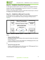
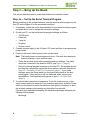
Getting Started Guide
APM883208-X1 X-Gene™ X-C1 Evaluation Kit
Introduction
Before installing this product, read the information at Important Safety Information
(page 9), which describes safe procedures for cabling and plugging in electrical
equipment.
Purpose of This Guide
The purpose of this guide is to enable evaluation kit users to:
•
•
Set up the kit
Connect the board to the host PC
How to Use This Guide
This guide contains numbered procedures that enable you to prepare the
evaluation board for use. The guide supports both Windows and Linux PCs and
workstations.
Step 1 — Review the Kit Contents (page 1)
Step 2 — Connect the Board (page 2)
Step 3 — Bring Up the Board (page 4)
Step 4 — Get the Most From the Documentation (page 8)
This document supports the Windows and Linux operating systems.
Step 1 — Review the Kit Contents
1. Open the shipping carton and position the parts on a clean flat surface.
2. Using the list shown in Table 1, verify that all parts are in the carton.
3. Visually inspect all parts to ensure that no damage has occurred during
shipping.
Table 1: X-Gene X-C1 Evaluation Kit Contents List
Description
APM883208-X1 X-Gene X-C1 Evaluation Board
Qty
1
Note: Requires an ATX power supply, a serial cable, and an Ethernet cable (sold
separately).
Document Issue 0.1
AppliedMicro Confidential
APM 2014-0001
Getting Started Guide — APM883208-X1 X-Gene X-C1 Evaluation Kit
Step 2 — Connect the Board
This section tells you how to connect the board to a host PC and to a power
source. See the following illustration for reference.
Step 2a — Establish a Serial Port Connection (page 3)
Step 2b — Establish an Ethernet Connection (page 3)
Figure 1: APM883208-X1 X-Gene X-C1 Board
1GE
Port 1
UART0
SDHC
1GE
Port 0
1GE Mgmt
Port
10GE
Port 0
USB 3.0
Host Port 1
USB 3.0
Host Port 0
USB to
JTAG
Figure 2: APM883208-X1 X-Gene X-C1 Connector Side View
2
AppliedMicro Confidential
Document Issue 0.1
Getting Started Guide — APM883208-X1 X-Gene X-C1 Evaluation Kit
Step 2a — Establish a Serial Port Connection
A serial cable provides the basic connection between the evaluation board and
the host PC. A serial terminal program is required on the host PC (for example,
minicom, Tera Term, or HyperTerminal).
Connect a serial cable between UART0 on the board and a serial port on the host
PC. Make a note of the host serial port used.
Step 2b — Establish an Ethernet Connection
An Ethernet connection enables TCP/IP communication between the board and
the host PC. You can connect either directly or through a LAN (as shown in
Figure 3).
Figure 3: Ethernet Connection Options — Direct or LAN
Either:
•
Connect the Board Directly
An Ethernet crossover cable provides a direct connection between the evaluation
board and the host PC.
Connect an Ethernet crossover cable between the 1GE Management Port on the
board and the Ethernet port on the host PC.
Or:
•
Connect Through Your LAN
Connect a standard Ethernet patch cable between the 1GE Management Port on
the board and an available port on your network.
Document Issue 0.1
AppliedMicro Confidential
3
Getting Started Guide — APM883208-X1 X-Gene X-C1 Evaluation Kit
Step 3 — Bring Up the Board
This section describes how to power and initialize the evaluation board.
Step 3a — Set Up the Serial Terminal Program
Before powering up the evaluation board, start the serial terminal program on the
host PC and configure it for the connected serial port:
1. If necessary, review the online documentation for your serial terminal program
for details about how to change the connection settings.
2. On the host PC, set the serial terminal program settings as follows:
• 115200 baud
• 8 data bits
• 1 stop bit
• No parity
• No flow control
3. Connect a power supply to the X-Gene X-C1 board and then to an appropriate
power source.
4. Power on the board via the power button on the board.
Note: The board powers up and begins auto boot. If the auto boot sequence
does not display on your serial terminal:
• Check the physical serial cable connection and port settings. The cable
should be connected to the board’s UART0; see Figure 1 (page 2).
• Verify the terminal program’s settings on the host PC. The program should
be using the configuration options as above and port that was selected at
Step 2a — Establish a Serial Port Connection (page 3). If you make
changes, press the Reset switch (on the board) and watch for the boot
activity again. If boot activity is still not displayed, either contact your
AppliedMicro® Field Applications Engineer or go to If You Need Help
(page 8).
5. You should abort the auto boot sequence. To do this, press any key on the
serial console within five seconds. If you miss this opportunity, cycle the Power
switch (on the board) to restart the autoboot and repeat your attempt to abort
the autoboot sequence by pressing any key within five seconds.
If the auto boot is aborted successfully, the serial terminal display will display the
following U-Boot prompt:
Mustang#
4
AppliedMicro Confidential
Document Issue 0.1
Getting Started Guide — APM883208-X1 X-Gene X-C1 Evaluation Kit
Step 3b — Set Up the Ethernet Connection
This section discusses how to set up a direct Ethernet connection between the
evaluation board and the host PC, as well as how to set up a LAN connection from
the board to a network.
Corresponding with the choice you made at Step 2b — Establish an Ethernet
Connection (page 3) to either connect directly or through a LAN, continue with
either:
•
•
Set Up a Direct Ethernet Connection (page 5)
or
Set Up Your LAN Connection (page 7)
Set Up a Direct Ethernet Connection
The evaluation board is pre-configured for a direct Ethernet connection and does
not require any changes. Therefore, the following instructions only cover the
necessary host PC changes.
Set the host PC’s TCP/IP connection to an IP address in the 192.168.1.x range
with a netmask of 255.255.255.0. This ensures correct communication with the
board. This is a non-routable, private IP range and is appropriate for a direct
connection.
The procedure for making this change on the host PC is specific to the operating
system being used. The following sections provide OS-specific procedures for
generic Windows and Linux systems. Administrator privileges are required to
make network configuration changes.
•
•
•
Set the IP Address — Windows (page 5)
Set the IP Address — Linux (Graphical Console) (page 6)
Set the IP Address — Linux (Text Console) (page 6)
Caution: Document all current network settings before making any changes.
Set the IP Address — Windows
1. Open the Control Panel.
2. Open Network Connections. If more than one connection icon is listed, contact
your IT or network administrator. Right-click either Local Area Network or
Wired Connection and select Properties to display a pop-up menu.
3. Click Open in the pop-up, then select the Properties option. The Properties
window shows a list of network clients and protocols used by this Ethernet
connection. Select Internet Protocol (TCP/IP) and click the Properties button.
4. Record the settings displayed in the Properties window. In the Properties
window, click the Advanced button and record the settings displayed in the
Advanced Settings window.
Document Issue 0.1
AppliedMicro Confidential
5
Getting Started Guide — APM883208-X1 X-Gene X-C1 Evaluation Kit
5. Return to the IP Properties window and select Use the Following IP Address,
then:
a) Enter 192.168.1.x in the Address field (x can be any value from 0 to 255
except 1, 62, and 255).
b) Enter 255.255.255.0 in the Subnet Mask field.
All other fields must be empty.
6. Select OK in this window and in the Connection Properties window.
These changes may require a reboot.
Note: Restore the original settings when you finish using the host PC with the
evaluation board.
Set the IP Address — Linux (Graphical Console)
1. Select Main Menu > System Settings > Network.
2. Select the Ethernet adapter for this connection, then select the Edit option.
3. Record the settings for this connection. Also, record the settings for the Route
and Hardware Device sheets.
4. Select Statically Set IP Addresses.
a) Enter 192.168.1.x in the Address field (x can be any value from 0 to 255
except 1, 62, and 255).
b) Enter 255.255.255.0 in the Subnet Mask field.
All other fields must be empty.
5. Select OK and close the Network Configuration window.
Note: Restore the original settings when you finish using the host PC with the
evaluation board.
Set the IP Address — Linux (Text Console)
1. Run the ifconfig application and record the inet address and Mask settings for
the Ethernet device to be used (to be restored later, if necessary).
The ifconfig application is typically stored in the /sbin folder.
2. Run the ifconfig application, providing parameters to set the IP address and
netmask, for example:
ifconfig eth0 192.168.1.x netmask 255.255.255.0
The eth0 value used here is typical, but may differ from the device you have
selected. The last IP address field x can be any number from 0 to 255 except 1,
62, and 255.
Note: Restore the original settings when you finish using the host PC with the
evaluation board.
6
AppliedMicro Confidential
Document Issue 0.1
Getting Started Guide — APM883208-X1 X-Gene X-C1 Evaluation Kit
Set Up Your LAN Connection
The evaluation board is pre-configured for a direct Ethernet connection and may
need to be changed to connect to a LAN correctly, as described in the following
steps:
1. Cycle the Power switch (on the board). The board begins auto boot.
2. Abort the auto boot sequence. To do this, press any key on the serial console
within five seconds. If you miss this opportunity, cycle the Power switch (on the
board) to restart the auto boot and repeat your attempt to abort the auto boot
sequence by pressing any key on the serial console within five seconds.
3. Reconfigure the evaluation board network as follows:
a) To set a new fixed IP address, enter the printenv command to display the
ipaddr var:
Mustang# printenv ipaddr
The serial console displays the ipaddr variable, which is represented by the
text displayed after ipaddr= as a result of the printenv command.
b) Enter the setenv command with the ipaddr variable modified according to
the LAN connection fixed IP address needed. For example:
Mustang# setenv ipaddr 192.168.1.62
c) To keep changes between power cycles, enter the saveenv command to
save the environment settings and then reset the board.
Mustang# saveenv
Note: When using setenv, all args must be entered on one line.
Document Issue 0.1
AppliedMicro Confidential
7
Getting Started Guide — APM883208-X1 X-Gene X-C1 Evaluation Kit
Step 4 — Get the Most From the Documentation
The following list shows the AppliedMicro documentation that is available:
•
•
•
This document
Evaluation Board User’s Manual
Evaluation Board Software User’s Manual
Additional Resources
Additional documentation is available for this kit and its components. For
processor Data Sheet, User’s Manual, board schematics, board layouts, Linux
image, and a firmware image for the board, go to the appropriate AppliedMicro
Web site:
Documentation: http://www.apm.com
If You Need Help
For help with using the evaluation kit, contact technical support via email at
[email protected].
8
AppliedMicro Confidential
Document Issue 0.1
Getting Started Guide — APM883208-X1 X-Gene X-C1 Evaluation Kit
Important Safety Information
This kit is intended to be used in a laboratory environment and is provided for
evaluation purposes only. End use conditions for unattended test configurations
must take into account a means of fire containment to ensure that potential flames
cannot propagate. Proper cooling must be provided to ensure that overheating
conditions are prevented. In addition:
•
•
•
•
These units are intended to receive power and logic signals from “Safety Extra
Low Voltage” circuitry.
From a safety perspective, these units have been evaluated for installation in
normal residential, light industrial, or commercial locations (Pollution Degree 2
Environments).
The connections on the hardware have been evaluated as Limited Power
Sources.
These units do not employ any Telecommunication Network Voltage (TNV)
Circuits.
To avoid a shock hazard:
•
•
•
Do not connect or disconnect any cables or perform installation, maintenance,
or re-configuration of this product during an electrical storm.
The power cord must be connected to a properly wired and grounded
receptacle.
Any equipment to which this product will be attached must also be connected
to properly wired receptacles.
When possible, use one hand to connect or disconnect signal cables to prevent a
possible shock from touching two surfaces with different electrical potentials.
Electrical current from power, telephone, and communications cables is
hazardous. To avoid shock hazard, connect and disconnect cables as described
below when installing, moving, or opening the covers of this product or attached
devices.
To connect the evaluation board:
1. Turn off all external devices and the board power supply. Ensure that the
board power supply cord is removed from the outlet.
2. Attach all signal cables to external devices first.
3. Attach all signal cables to the board.
4. Plug the board power supply cord into the outlet. Turn on all external devices
and the board power supply.
To disconnect the evaluation board:
1. Turn off all external devices and the board power supply.
2. Remove the board power supply power cord from the outlet.
3. Remove all signal cables from the board. Disconnect the board power supply
from the board.
Document Issue 0.1
AppliedMicro Confidential
9
Getting Started Guide
APM883208-X1 X-Gene X-C1 Evaluation Kit
Applied Micro Circuits Corporation
215 Moffett Park Drive, Sunnyvale, CA 94089-1322
Phone: (408) 542-8600 Fax: (408) 542-8601
Send Email to [email protected]
or visit the AppliedMicro website at http://www.apm.com
AppliedMicro reserves the right to make changes to its products, its data sheets, or related
documentation, without notice and warrants its products solely pursuant to its terms and conditions
of sale, only to substantially comply with the latest available data sheet. Please consult
AppliedMicro’s Terms and Conditions of Sale for its warranties and other terms, conditions and
limitations. AppliedMicro may discontinue any semiconductor product or service without notice,
and advises its customers to obtain the latest version of relevant information to verify, before
placing orders, that the information is current. AppliedMicro does not assume any liability arising
out of the application or use of any product or circuit described herein, neither does it convey any
license under its patent rights nor the rights of others. AppliedMicro reserves the right to ship
devices of higher grade in place of those of lower grade.
APPLIEDMICRO SEMICONDUCTOR PRODUCTS ARE NOT DESIGNED, INTENDED,
AUTHORIZED, OR WARRANTED TO BE SUITABLE FOR USE IN LIFE-SUPPORT
APPLICATIONS, DEVICES, OR SYSTEMS, OR OTHER CRITICAL APPLICATIONS.
AppliedMicro and AMCC are registered trademarks of Applied Micro Circuits Corporation. X-Gene
is a Trademark of Applied Micro Circuits Corporation. ARM is a registered trademark of ARM
Limited. All other trademarks are the property of their respective holders.
Copyright © 2014 Applied Micro Circuits Corporation. All Rights Reserved.
APM 2014-0001
AppliedMicro Confidential
Document Issue 0.1