1
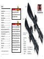
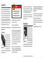
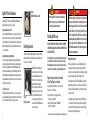
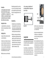
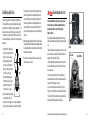
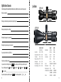
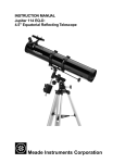
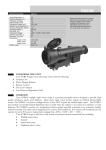
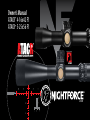
Owner’s Manual
ATACR™ 4-16x42 F1
ATACR™ 5-25x56 F1
FIRST FOCAL PLANE
2015 V1
Contents
Nomenclature and features........................................................... 3
Focusing the reticle....................................................................... 4
Parallax adjustment...................................................................... 5
DigIllum™ reticle illumination....................................................... 6
Battery replacement .................................................................... 6
Installing the riflescope................................................................. 7
Leveling the reticle....................................................................... 9
Establishing a sight-in zero.......................................................... 10
Setting the ZeroStop™ elevation adjustment (5-25 x 56 F1).......... 11
Setting the ZeroHold™ elevation adjustment (4-16 x 42 F1).......... 12
Setting the windage adjustment................................................. 14
Power Throw Lever (PTL™)........................................................... 14
Caring for your riflescope............................................................. 15
Warranty.................................................................................... 16
Warranty registration.................................................................. 17
Owner’s comments...................................................................... 18
Specifications.............................................................................. 19
Record the riflescope serial number below for future reference:
_____________________________________
2
5-25 x 56 F1
WARNING!
H
Make sure that your rifle is not loaded before
proceeding. Reconfirm that the chamber is empty if you
stop the procedure then resume later.
Nomenclature and features
A
4-16 x 42 F1
WARNING!
Nightforce Optics, Inc. does not authorize the export of
these items outside of the United States of America.
Riflescopes and accessories listed within, are controlled
for export by the U.S. Department of State, under the
International Traffic In Arms (ITAR) regulations (22 CFR,
Parts 120-130), and/or the Department of Commerce
under the Bureau of Industry and Security Export
Administration Regulations (15 CFR, Parts 730-774).
To export these products outside of the United States of
America, you must comply with the regulatory agency’s
license and documentation requirements.
I
Controls and features are the same for both
models unless noted otherwise
A: Objective/Objective Lens
B: Eyepiece
C: Eyepiece Lock Ring
D: Power Throw Lever
E: Power Zoom Ring
F: Parallax Adjustment
G: Digillum™ Illumination Control and Battery
Compartment
K
F
J
E
G
C
B
H: I: J: K: ZeroStop™ Elevation Adjustment (5-25x)
ZeroHold™ Elevation Adjustment (4-16x)
ZeroHold™ Button (4-16x)
Windage Adjustment (under cap)
D
3
Focusing the Reticle
There are two user-adjustable optical settings on Nightforce ATACR™ F1
riflescopes: the reticle focus and the parallax adjustment. The reticle focus
is used for setting the reticle focus to match your particular vision. It should
not be used to try to focus for parallax. If you plan to wear vision correction
when shooting, then set this focus while wearing your corrective lenses.
The reticle focus should be set before setting the parallax adjustment. If the
reticle focus is inadvertently set to the extreme ends of travel it can adversely
effect parallax. Record the number of turns you have made on the eyepiece
from the original factory setting so you can return to it if needed.
Note: All Nightforce riflescopes are factory set for average eye strength, so this
adjustment may not be necessary.
Reticle Focus Adjustment
Grasp the eyepiece with one hand and
the locking ring with the other and
rotate the eyepiece counter-clockwise,
turning it away from the lock-ring while
holding the lock-ring, power zoom ring
and the riflescope to keep them from
Locking ring
turning with the eyepiece. Several turns
Figure 1: Reticle Focus
of the eyepiece may be necessary to
achieve any measurable difference. To achieve an out-of-focus starting point
for your vision, you may need to turn
Eyepiece
4
WARNING!
To avoid permanent eye damage or blindness,
do not look directly at the sun or other
extremely bright lights through the riflescope.
the lock-ring several turns inward first, then turn the eyepiece inward as
needed to achieve an out-of-focus position.
1) Set the power zoom ring at the highest magnification.
2) On riflescopes with parallax adjustment, set it to the infinity setting ∞.
3) Look through the riflescope eyepiece at a light colored background such as
a white wall, overcast sky, or drape a thin white cloth over the objective to
eliminate background clutter. Determine if the reticle is clear and in focus
instantly when you look through the eyepiece. Be aware that staring at
the reticle for more than two seconds during this process will cause your
eye to compensate, resulting in a false indication of reticle focus. Look
away for a few seconds then retry for best results. You are looking for a
sharp, crisp and well defined reticle image.
4)If adjustment is necessary, follow the steps outlined here. Due to the way
the human eye focuses, best results are usually obtained by turning the
eyepiece inward until the reticle is slightly blurred then moving it outward
until sharp focus is obtained. Refer to Figure 1.
Once the desired reticle focus is achieved, lock the eyepiece in place by
turning the lock-ring into firm contact with the eyepiece while holding the
eyepiece in position. Tighten the lock ring against the eyepiece so that the
eyepiece, lock ring and power zoom ring move as a single unit.
If the reticle tends to fade in and out of focus, or you are experiencing eye
strain with extended shooting sessions, that is an indicator that the reticle is
not properly focused for your eye.
Parallax Adjustment
Nightforce ATACR™ F1 riflescopes have a
parallax adjustment mechanism. Parallax
is the apparent movement of the reticle in
relation to the target as the shooter moves
his eye across the exit pupil of the riflescope,
caused by the target and the reticle being
on different focal planes. While keeping the
Figure 2:
rifle still and looking through the riflescope,
Parallax Adjustment
a nod of the head up and down will quickly
determine if parallax is present. If parallax has been eliminated, the reticle
will remain stationary in relation to the target regardless of eye placement.
For the latest updates and information regarding our products, visit www.NightforceOptics.com.
Note: The greater the distance, the greater the parallax error becomes.
Especially at longer distances, significant sighting error can result if
parallax is not removed.
Nightforce ATACR™ F1 riflescopes have a side parallax adjustment found on
the left side of the riflescope, directly opposite the windage adjustment.
Parallax adjustments are marked with approximate distances.
Environmental conditions may cause the distances to vary from indicated.
Minute of Angle models are indicated in yards, while Mil-Radian models are
indicated in meters.
The parallax adjustment should not be used as a range estimator.
5
DigIllum™ Reticle Illumination
Figure 3:
DigIllum™ illumination control
Nightforce ATACR™ F1 riflescopes feature DigIllum™ digital illumination,
including both red and green options. See Figure 3.
Turning the illumination on and off
To turn on your DigIllum™ illuminated reticle, simply press and release the illumination control located on the center of the side parallax adjustment. The
reticle will illuminate to the last used intensity and color setting. To turn your
DigIllum™ illuminated reticle off, press and hold the illumination control for
1-3 seconds and release.
Adjusting illumination intensity (brightness)
Once turned on, by repeatedly pressing and releasing the illumination control you will change the intensity of the reticle. There are multiple intensity
levels in the standard illumination mode. When the illumination reaches
its minimum or maximum intensity, the reticle will flash three times. After
reaching the minimum or maximum intensity, continuously pressing and releasing the illumination control will either increase or decrease the intensity
away from the respective setting.
Selecting the reticle color
The DigIllum™ illuminated reticle allows the user to choose between red or
green reticle illumination. By pressing the illumination control for about five
seconds, the color will change from red to green or green to red.
6
WARNING!
Make sure that your rifle is unloaded prior to installing any
Nightforce riflescope or accessory. Recheck the chamber if
you stop the procedure and resume later.
Installing the Riflescope
Battery Replacement
The battery is held underneath the adjustment cover, which is removed by
turning the knurled portion of the adjustment cover counterclockwise until
the cover comes off. See Figure 4.
Figure 4:
Battery replacement
With DigIllum™ reticle illumination, your
battery can produce 29 hours of continuous
use at maximum illumination and up to
140 hours at its lowest intensity. Replace
depleted batteries with an Energizer®
CR2032 or equivalent. Install the battery
with the positive (+) side up. Don’t forget
to turn off the illumination when not in
use to prevent depletion of the battery. An
auto-shutoff will turn off illumination after
one hour of no activity.
FAILURE TO PROPERLY INSTALL THE RIFLESCOPE MAY CAUSE EQUIPMENT
AND/OR PERSONAL DAMAGE WHICH CAN RESULT IN EQUIPMENT FAILURE,
SERIOUS INJURY OR DEATH.
Note: Please take time to record your serial number on the inside front
cover of this booklet. It can then be easily referenced for your online
Warranty Registration. Once the scope has been installed, you may not
be able to read the serial number, as your rings/mounts may cover it.
Nightforce Torque Specifications for standard and
X-Treme™ Duty Rings, Bases and Mounts
• Base and Direct Mount™ attachment screws - 25 inch pounds
• Ring top screws - 25 inch pounds
• Ring crossbolt nut - 4-screw design, 68 inch pounds;
6-screw design, 100 inch pounds
• Unimount™, Extended Unimount™ and MagMount™
crossbolt nut - 68 inch pounds
For the latest updates and information regarding our products, visit www.NightforceOptics.com.
WARNING!
With hard-recoiling rifles, serious injury or even death can result
from eyepiece impact with the shooter during the recoil process
when discharging the firearm. Be certain that your installation
provides sufficient eye relief for the recoil generated by your rifle before shooting the firearm. NOTE: Give special attention to
this warning when shooting uphill and/or from a prone position.
These shooting conditions can dramatically reduce eye relief.
PLEASE maintain maximum eye relief when shooting heavy recoiling and/or magnum firearms.
Ring and Base Selection
Your riflescope and rifle are only as good as the link between them. The
mounting of your riflescope is as important as the bedding of the rifle’s
action to the stock. To ensure the highest level of performance, the following
steps in the mounting procedure must be followed as described.
We recommend standard or X-Treme™ Duty Nightforce bases, along with
Nightforce 34mm rings and one-piece mounts for a solid and precise installation. Please use the following guidelines to select the proper mounting
solutions for your rifle.
• A high quality ring and base combination using a 1913 Mil. Std. type rail
is recommended for field use and/or high-recoil applications. Nightforce
standard and X-Treme™ Duty 34mm rings, bases, Unimount™ and MagMount™ are ideal for virtually all applications.
7
Mount Installation
Note: Do NOT lap the Nightforce Unimount™, Extended Unimount™,
Direct Mount™, MagMount™ or Ultralite™ rings. Lapping is not necessary with these Nightforce accessories. Lapping these products will
void the Nightforce accessory warranty and may lead to slipping and/or
crushing of the Nightforce riflescope main tube. Other manufacturer’s
ring/base combinations may or may not require lapping.
Attaching the Base to the Action
Once you have determined that the base-to-action mating is acceptable,
install the base to the action, torquing the mounting screws to the manufacturer’s specifications.
Attaching Rings to the Base
C lean/degrease the inside of the rings and then clean the outside of the
scope tube before installing in the rings.
Install the rings on the base per the manufacturer’s specifications using the
proper torque on the locking mechanism. Avoid positioning the rings where
they will make contact with the adjustment assembly, the objective bell section, or the power zoom ring on the riflescope body. Apply forward pressure
to the ring while tightening it in place to keep the cross bolt on the ring in
firm contact with the forward surface of the cross slot in the base.
With other brands lapping may be required. If the scope lays into the rings
stress-free, there is no need to lap the rings. If required, we recommend lapping be done by a qualified technician or gunsmith. Do not overlap the rings.
Damage to the scope from improper lapping/installation is not covered by
the warranty.
Figure 6
3" - 4"
These two surfaces should be
parallel to each other
Mounting the Riflescope
1) For initial fitting of the riflescope to the rifle, set the Nightforce riflescope
to the highest magnification. Place the riflescope in the lower portion of
the rings as far forward as possible. Install both ring tops. Tighten ring top
screws with just enough tension to hold the riflescope where positioned,
while still allowing smooth movement fore and aft and rotationally.
2) Hold the rifle in your normal shooting position with the riflescope positioned fully forward in the rings, preferably while adjusted to maximum
magnification. Place your head as far forward on the stock as you might
position it in field use. Slowly move the riflescope back just to the point
where the full field of view is obtained. It is recommended to mount the
riflescope at this position with as much eye relief as possible (3.5”–4”) or
slightly forward to ensure maximum eye relief. (Figure 5)
With Nightforce rings and one-piece bases you should not lap the rings.
8
Note: Please see warning on page 7 regarding sufficient eye relief.
Eye relief will change with the thickness of the clothing you wear and
may need to be readjusted.
For the latest updates and information regarding our products, visit www.NightforceOptics.com.
Figure 5: Eye relief
Leveling the Reticle
For precision shooting, the reticle and the rifle need to be squared, or plumb,
to each other. Any out-of-square condition can cause sighting errors that will
be magnified even more at longer distances.
The reticle in all Nightforce scopes is confirmed plumb with the flat surface
on the bottom of the adjustment saddle. (Figure 6) You can use pin gauges, a
sliding sine bar or flat shims to align the flat surface with the top of the scope
rail. To level the reticle using a plumb line, follow the three steps that follow.
1) Level the rifle on a steady rest such as sandbags or a stable shooting rest.
This can be accomplished with a bubble level attached to the riflescope
base, or on a flat section of the action.
2) Use a plumb line or some other known plumb vertical line at a distance
from the rifle where you can see it clearly through the riflescope. A
distance of 100 yards is recommended, but good results can often be
obtained as close as 50 yards.
3) Center the reticle on the plumb line and rotate the riflescope in the rings
until the vertical line of the reticle is parallel with the plumb line. Recheck
the rifle level and adjust the reticle position as needed. When the rifle and
the reticle is plumb, tighten all ring top screws evenly until the riflescope
is secure in the rings. Recheck that the rifle has remained level and that
the reticle is plumb one more time, adjust as needed, then torque the
screws to the recommended torque settings. Your Nightforce riflescope is
now properly mounted.
9
Establishing a Sight-in Zero
A quick way to get your first shot on target with a new installation is to
first bore sight the riflescope. A simple yet reliable method is by looking
through the bore at a round, high contrast target, approximately 5”– 6” in
diameter, that can be seen clearly with the naked eye at either 25, 50 or
100 yards/meters, yet is small enough to “float” in the center of the rifle
bore when viewed through the opened action. This can save you time and
ammunition.
1.Ensure that the rifle is unloaded and
the chamber is empty. Remove the bolt
and place the rifle on a steady rest.
2. Looking through the bore from the
action end, center the round target
downrange so that it is floating in the
center of the bore, then adjust
the elevation and windage adjustments until the reticle is centered on
the target while the target is still
centered in the bore. See Figure 9.
4. Without changing the adjustments, move the rifle to center the reticle on
the target. Carefully turn the windage and elevation adjustments without
moving the rifle, until the reticle is aligned on the center of the bullet hole
from that first shot on the target.
5. Fire at least a three-shot group at the desired close-range zero distance,
then fine-tune your zero as needed.
Figure 7
3. If you feel confident in the bore sighting,
proceed to live firing at 25, 50 or 100
yards/meters. To aid in the sight-in process, be sure your sight-in target is
large in size, and offers a contrasting color (i.e., white). After confirming
10
point of impact, proceed to step four. Note: if you have sighted in at 25
yards/meters, you will need to move the adjustments four times more
than you would with a 100 yard/meter sight-in. If you sighted in at 50
yards/meters, you will need to move the adjustments two times more
than you would with a 100 yard/meter sight-in. If the first shot isn’t on
target, recheck your bore sighting and/or move to a 25 yard/meter sightin distance.
Elevation Adjustments (5-25x)
Please visit www.NightforceOptics.com for a step-by-step video
tutorial on this process and advanced setting methods that can
maximize the performance of your ZeroStop™-equipped
Nightforce riflescope.
After you have determined the ammunition that performs best for your
intended use and established the zero/sight-in, please follow these instructions:
1. Remove elevation turret cap by loosening the two set screws 1 to 2 turns
but do not remove the screw entirely. The dial should rotate freely and no
adjustment “clicks” should be felt. See Figure 8.
2. Lift the cap upward with a slight twisting motion to remove it from the
body. You should feel slight resistance but not feel any “clicks”. Set the cap
aside on a clean surface.
3. You have now exposed the ZeroStop™ clutch assembly. Take care to
maintain the cleanliness of the inside of the cap and the clutch area. Do not
remove any of the lubricating grease. See Figure 9.
4. Loosen each of the four Allen head screws on the ZeroStop™ clutch
assembly 1 to 2 turns. DO NOT remove the screws from the clutch assembly.
5. To set the ZeroStop™ clutch assembly, rotate the upper clutch face downward/clockwise until it is firmly against the lower clutch face.
For the latest updates and information regarding our products, visit www.NightforceOptics.com.
Set Screw
Figure 8
Set Screw x4
Upper Clutch Plate
Lower Clutch Plate
Turret
Body
Figure 9
11
ZeroStop Clutch
Assembly
Upper Clutch Face
Upper
Clutch Face
to move up due to the compressed air resistance created by the O-ring seal.
Align the “0” (zero) fixed index mark on the engraved scale of the adjustment
cap with the center line on the scope body (Figure 8) and tighten both set
screws to 4 inch-pounds.
NOTE: If no calibrated torque driver is available for 4 inch-pounds,
hold the short end of the Allen wrench between your thumb and
finger to turn the wrench and tighten to slight resistance.
Lower Clutch Face
Lower Clutch Face
Figure 10
Figure 11
Elevation Adjustments (4-16x)
Note: You should not feel any “clicks” or resistance while making this adjustment. See Figure 10.
6. While holding the clutch mechanism in position, tighten the four Allen
head set screws on the clutch assembly evenly in an “X” pattern. Do not
over-tighten the screws as this can damage the clutch assembly. Tighten one
screw until you feel slight resistance, then move to the next screw in the “X”
pattern. Continue to do the same for all four screws. Now repeat the “X” pattern and tighten the screws to 4 inch-pounds. If no calibrated torque driver
is available, hold the short end of the Allen wrench to tighten the screws
and only use your thumb and finger to turn the wrench. This will provide
sufficient torque. See Figure 11.
7. To reinstall the adjustment cap, center it over the adjustment body, and
press down lightly while turning the adjustment cap clockwise until it moves
into position. Keep downward pressure on the adjustment cap as it may tend
The Nightforce 4-16x42 F1 has a ZeroHold™ elevation cap (Figure 12).
Once you have established your zero, you can now reset the ZeroHold™
cap. This will set your ZeroHold™ at your zero position and allow for 2
Mils/5 MOA of travel below zero.
12
For the latest updates and information regarding our products, visit www.NightforceOptics.com.
1) Loosen the two opposing set screws that are located perpendicular to the ZeroHold release button by utilizing a 5/64” hex key. Rotate
the dial until “0” lines up with the reference line on the body tube and
retighten the set screws to 10 inch pounds. (Figure 13)
2) Dial to 2 Mils/5 MOA under zero (downward direction) and note
position of the dial. If you cannot dial 2 Mils/5 MOA under zero,
see NOTE 2.
3) Remove the ZeroHold dial by loosening the two setscrews with a
5/64” hex key and set aside the cap. (Figure 14)
4) Loosen the four size #0 Phillips screws 1/2 to one turn (until
pressure is relieved), but do not remove them completely. (Figure 15)
Figure 12
Figure 13
Figure 14
Figure 15
Figure 16
Figure 17
5) Rotate black clamp wheel clockwise until bottomed out with no
further movement. Then retighten the four Phillips screws in an even
“X” pattern to two inch pounds each (approximately 1/8 turn past snug).
(Figure 16)
6) Place the ZeroHold dial back on and rotate to 2 Mils/5 MOA below
zero. (Figure 17) Tighten the opposing set screws to 10 inch pounds.
7) Return the dial to the “0” position and the ZeroHold
should engage.
NOTE 2:
1) If you cannot dial 2 Mils/5 MOA below zero, you will need to add
additional travel by adjusting the elevation clamp wheel under the adjustment cap. Remove the ZeroHold dial by loosening the two setscrews
with a 5/64” hex key and set aside. (Figure 14)
2) Loosen the four size #0 Phillips screws 1/2 to one turn (until pressure is relieved), but do not remove them completely. (Figure 15) Rotate
the center clamp wheel counter-clockwise approximately ¼ of a turn,
being careful not to unthread the upper wheel off of the adjustment. Retighten the four Phillips screws in an even “X” pattern to two inch pounds
(approximately 1/8 turn past snug).
3) Place the ZeroHold dial back on and rotate to two Mils below zero.
Tighten the opposing set screws to 10 inch pounds. The turret should
now allow 2 Mils/5 MOA of travel below the sight-in zero.
13
Setting The Windage Adjustment
Figure 20
The windage adjustments on ATACR F1s are included with a protective,
screw-on cap from the factory. The windage adjustment is waterproof and
can be used without the cap. A trim ring is included to protect the threads if
using as an external adjustment (Figure 21).
1. Remove the protective cap.
2. Loosen the set screw one turn on the windage adjustment and the dial
should rotate freely. (Figure 18) NOTE: You should not feel any clicks when
adjusting the dial at this point.
3. While applying inward pressure to the dial, re-index to zero. (Figure 19)
4. Retighten the setscrew to four (4) inch pounds. (Figure 20)
Figure 18
14
Figure 19
Figure 21
Caring for Your Riflescope
With proper care your Nightforce riflescope will give you many years of
dependable service. Be sure to use your lens covers whenever you are not
using your riflescope.
Cleaning the Riflescope Exterior
PTL™ (Power Throw Lever)
The PTL™ (Figure 22) is designed to
allow rapid magnification changes, just
by feel. First, ensure that your firearm
is unloaded. Your riflescope arrives with
a flush black insert screwed into the
power zoom ring. To remove it, turn
it counterclockwise with the supplied
5/64" hex key. You can then install the PTL™ (included with your riflescope)
by screwing it clockwise into the threaded hole. Tighten it securely with the
hex key, but take care not to overtighten the PTL™ to avoid stripping the
threads or hex hole. Keep the insert in a secure place should you wish to
remove the PTL™ in the future and reinstall it.
Figure 22
For the latest updates and information regarding our products, visit www.NightforceOptics.com.
Clean the riflescope body with a clean cloth lightly moistened with clean water or alcohol. Do not use strong solvents. While cleaning your rifle, be sure
to protect your riflescope’s lenses by installing the covers that came with the
riflescope (or equivalent covers). Ammonia-based bore solvents can destroy
the coating on the glass. Avoid spilling gun cleaning solvents anywhere on
the riflescope.
In the event of submersion in mud, sand, dirty or salt water, flush the outside
of the riflescope with clean water to remove encrusted material and salt. If
your riflescope came with screw- on adjustment covers, install them before
flushing with water. Wipe the outside metal surfaces dry with a soft cloth
then proceed to the step below.
Cleaning Lenses
We recommend using a Nightforce cleaning kit A130 to care for the lenses
on your riflescope. The kit contains an ultrasoft brush, microfiber cloth and
cleaning solution.
With the lens facing down to allow the debris to fall away from the surface,
remove loose dirt and dust with compressed air and/or a lens brush. Do NOT
use high-pressure compressed air from cans (such as found in office supply
stores). They can, and have, been known to destroy lens coatings. If there is
grit stuck to the lens that won’t come off with the compressed air or a brush,
flushing the surface with alcohol or distilled water will prevent that grit from
being rubbed into the glass by the cleaning swabs.
Using a soft, clean, lint-free cotton swab or lens cleaning cloth, and lens
cleaning fluid applied to the swab, clean the lens starting in the center,
working to the outside in a circular motion. Make only one pass to the edge
where the glass meets the metal. Once you reach the edge of the lens, do
not re-use that swab as it will often contain abrasive grit that will scratch
the surface. Start over in the center with a new swab and repeat the process
until the glass is clean. Use a very small amount of cleaning solution for the
last pass to prevent streaks.
Long Term Storage
If the riflescope will not be used for an extended period, remove the battery
and store it separately. Keep the riflescope in a cool, dry, dust-free location.
For a list of frequently asked questions, video instruction,
information on service and on Nightforce accessories, visit
www.NightforceOptics.com.
15
We are proud to back up Nightforce ATACR™, B.E.A.S.T.™, Benchrest, Competition™,
NXS™ and SHV™ riflescopes with a transferable Limited Lifetime Warranty which
covers mechanical defects in materials and workmanship in the optical and mechanical components of the riflescope. In the event of a defect in materials or workmanship that is covered by this warranty, we will either repair the riflescope or replace it
at no charge, with a comparable product at our discretion.
Exclusions to this warranty include intentional or accidental damage, abuse, misuse,
unauthorized modifications or repairs, and improper mounting. This warranty does
not cover any consequential or incidental damages resulting from the inability to
use the riflescope. Any serial number obliteration or alteration on the product will
void the warranty. SHV™ models maintain waterproof integrity with their protective
caps installed.
To ensure warranty coverage, please register online or fill out completely and mail
in the provided warranty card found in the back of the owner’s manual, along with
a copy of the sales receipt. The warranty begins on the date the product was purchased by the original owner. The optical and mechanical components are covered
without time limitations. The riflescope’s electronic components are covered for a
period of three years.
This warranty gives you specific legal rights, and you may also have other rights
which vary from state to state. Some states do not allow the exclusion or limitation
of incidental or consequential damages, so the above limitations or exclusions may
16
Nightforce Warranty Registration Card
Before sending a riflescope in for service, please call Nightforce Optics, Inc.
at the number below, to determine if the problem can be resolved without
sending us the product. All returns must be accompanied by a Return
Merchandise Authorization (RMA) number. Failure to do so can result in
lost merchandise and/or severely delayed service time.
Name:________________________________________________________________________________
Activate your warranty at www.NightforceOptics.com/WarrantyRegistration and be eligible for product support, updates and additional Nightforce
gear. If you do not have Internet access, please tear out, fill in and return this product registration card within 30 days of purchase. Return to the address
below along with a copy of your purchase receipt. We retain this card for warranty eligibility.
• Remove any mounting rings or accessories other than dust covers and the original
sunshade.
• Record and keep on hand the serial number.
• Include with the riflescope a detailed description of the defect(s), the RMA number,
your name, phone number and the address you wish the riflescope returned to.
• Place the boxed or protectively wrapped riflescope in a well-padded outer box
insured for replacement value and send it shipping prepaid, to the appropriate
address below. Write the RMA number on the outside of the package.
U.S.A. & Canada:
Nightforce Optics, Inc.
Attention: Service Dept.
336 Hazen Lane
Orofino, Idaho 83544
International:
Nightforce Optics
Attention: Service Dept.
11 Manton Street
Hindmarsh, SA 5007 Australia
tel 208.476.9814
fax 208.476.9817
www.NightforceOptics.com
tel +61 (0)8 8440 0888
fax +61 (0)8 8346 0504
www.NightforceOptics.com
Be sure to register your warranty at
www.NightforceOptics.com/WarrantyRegistration
Address:______________________________________________________________________________
Please detach here
Limited Lifetime Warranty
not apply to you. Some states do not allow limitations on how long an implied
warranty lasts, so the above limitations may not apply to you.
City: _______________________________________ State: _____________ Zip: ________________
Phone No.: __________________________________ Email: _________________________________
Model : _____________________________________ Serial No. : ______________________________
Date of Purchase: ____________________ Purchased From: ___________________________________
Please take a moment to provide your comments on the following page.
To locate your serial number: The serial number for all new Nightforce scopes can be found on the bottom of the elevation/windage adjustment/parallax adjustment saddle. On some earlier models, it can be found on top of the tube body in front of the elevation adjustment, or on the bottom of the tube body in front of the power change
ring. Please contact Customer Service if you need help in locating the serial number on older riflescopes.
Attach a copy of your receipt and send to: Nightforce Optics, Inc.
For the latest updates and information regarding our
products, visit www.NightforceOptics.com.
336 Hazen Lane
Orofino, Idaho 83544
Register online at
www.NightforceOptics.com/WarrantyRegistration
17
Nightforce Owner’s Comments
Specifications
Your feedback and suggestions will help us maintain the high level of quality and customer service Nightforce owners have come to expect. We encourage your input.
Why did you choose Nightforce?
ATACR™4-16x42 F1
G
F
B
What changes or modifications would you recommend be made to improve this product?
ATACR™ 5-25x56 F1
G
F
Please detach here
What hunting/shooting magazines do you normally read?
What hunting/shooting television programs do you like to watch?
Do you participate in Internet forums or blogs? Which ones?
How did you hear about Nightforce products?
Are you a member of a local rifle shooting club or range? n Yes n No Do you participate in any of the following competitive shooting events?
If so, please check the appropriate box: n Long-range benchrest n Short-range benchrest n F-Class n Precision tactical n 3-Gun n Tactical
n Other (please explain)_____________________________________________________________________________
18
E
A
What new products would you like to see offered by us?
Do you travel to participate in competitive shooting events? n Yes n No
D
C
If so, how far do you typically travel? ___Miles ___Hours
B
D
C
E
A
4-16x42 F1 5-25x56 F1 (Inches/millimeters)
A. Overall length
12.6/32015.37/390
B. Objective outer diameter 1.97/50
2.56/65
C. Tube diameter
1.34/341.34/34
D. Eyepiece outer diameter1.77/45 1.81/46
E. Mounting length 6.3/1605.9/150
F. Front mounting length2.0/51 1.65/42
G. Rear mounting length2.53/64 2.48/63
4-16x42 F1
Exit pupil diameter
4x :10.3mm
16x: 2.7mm
Field of view
4x: 26.9 ft
@100 yards/meters
16x : 6.9 ft
4x: 8.1 m
16x: 2.1 m
Eye relief
85-90mm/3.35-3.54"
Parallax adjustment
45 yd–∞
Weight (ounces/grams)30/850
Internal adjustment range e: 89 MOA/26 Mil
w: 60 MOA/18 Mil
Click value .250 MOA/.1 Mil
5-25x56 F1 5x: 8.3 mm
25x: 2.3 mm
5x: 18.7 ft
25x: 4.9 ft
5x: 5.7 m
25x: 1.5 m
85-90mm/3.35-3.54”
45 yd–∞
37.6/1066
e: 120 MOA/34.9 Mil
w: 80 MOA 23.7 Mil
.250 MOA/.1 Mil
19
MOAR™
All trademarks, graphics and designs herein are the property of Nightforce
Optics, Inc. Product specifications are subject to change without notice.
Products may differ in appearance from those shown here; not responsible
for typographical errors. Visit www.NightforceOptics.com for current
information, tutorials, and video. Lightforce USA, dba Nightforce Optics, Inc.
®Nightforce Optics, Inc. 2015 2/15
Factory/Headquarters U.S.A.
Customer Service, Technical & Warranty:
Nightforce Optics, Inc.
336 Hazen Lane
Orofino, ID 83544
tel 208.476.9814 • fax 208.476.9817
[email protected]
Marketing:
Marketing Department
Nightforce Optics Inc.
2749 Providence Church Road
Lavonia, GA 30553
tel 706.508.4908 • fax 706.449.0930
[email protected]
North American Dealer Sales:
Nightforce Optics, Inc.
2749 Providence Church Road
Lavonia, GA 30553
tel 706.434.8950 • fax 706.449.0930
[email protected]
European, Asian & African Sales:
Nightforce Optics, Inc.
2749 Providence Church Road
Lavonia, GA 30553
tel 706.434.8952 • fax 706.449.0930
[email protected]
Military, Government & Law Enforcement:
Nightforce Optics, Inc.
2749 Providence Church Road
Lavonia, GA 30553
tel 706.434.8953 • fax 706.449.0931
[email protected]
Australian & South Pacific Sales:
Nightforce Optics
11 Manton Street
Hindmarsh, SA 5007 Australia
tel +61 (0)8 8440 0888
fax +61 (0)8 8346 0504
International Warranty & Service:
Please contact your country’s authorized Nightforce
Optics distributor and/or retailer for instructions. A list
of international distributors and dealers can be found at
www.NightforceOptics.com.