1
Fairchild Semiconductor
Application Note 1022
February 1997
ABSTRACT
Designing IC’s, boards, and systems with a DFT strategy
that utilizes boundary-scan, will make a quantum improvement in test development cycle-time, and fault coverage
both in production and in the field. Tools are commercially
available that automate design, test development, and ultimately embedded test for IEEE 1149.1 compatible systems.
This paper is intended to familiarize designers and test engineers with the advantages of boundary-scan at the system
level as well as present the architectural and implementation
challenges of developing Fairchild’s SCAN EASE software.
For more information, refer to AN-1037, “Embedded IEEE
1149.1 Test Application Example.”
The boundary register is integrated into the input/output cells
of the device. While in Interconnect Test Mode (Extest command is active) data shifted into the boundary registers’ output cells is driven onto the outputs; and data driven onto the
device’s inputs is sampled by the input cells and shifted out
for comparison to expected results. This simple process of
shifting data, updating output cells, and sampling input cells,
is the basic algorithm for board level interconnect fault testing.[1,2,3]
INTRODUCTION
Boundary-Scan Fundamentals
The terms, 1149.1, 0.1, Boundary-Scan, and JTAG, are used
synonymously in the industry and throughout this paper.
IEEE Std 1149.1 defines a standard architecture for designing Boundary-Scan test circuitry into digital integrated circuits for the purpose of testing the IC and the interconnections between IC’s on a board or module. All 1149.1
compliant devices must have a Test Access Port (TAP) with
4 required pins: Test-Data-Input (TDI), Test-Data-Output
(TDO), Test-Mode-Select (TMS), and Test-Clock (TCK). A
fifth pin for Asynchronous Test Reset (TRST*) is optional (*
means active low). See Figure 1.
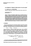
BOARD LEVEL BOUNDARY-SCAN TEST COVERAGE
At the board level, boundary-scan components are daisy
chalned (TDI to TDO) to form a single scan chain. See Figure 2. Boards comprised of 100% 1149.1 compliant components, can be tested with a vector set generated by ATPG
(Automatic Pattern Generation) software to 100% fault coverage with a 4-wire JTAG tester, while achieving a quantum
reduction in test development time and eliminating the need
for expensive in-circuit testers. In addition, faults are automatically isolated to the NET, and in the case of opens, to the
node (unit/pin).
AN012143-2
FIGURE 2. Simple Board
Boundary-Scan Implementation
© 1998 Fairchild Semiconductor Corporation
AN012143
www.fairchildsemi.com
AN-1022
AN012143-1
FIGURE 1. Device Hardware
Boards that do not have 100% boundary-scan components
can greatly benefit from this methodology also. In fact, even
a single chip with boundary-scan will simplify the test development effort, and may improve the testability of the board.
Especially if the boundary-scan component is a complex sequential device. For this reason, boundary-scan has become
a required feature of microprocessors, FPGAs and ASICs for
many board manufacturers.
The boundary-scan cells are often called “virtual nails” or
“silicon nails”, since they provide the same capability as
physical test points in a bed-of-nails fixture.[3] The task of
generating board level fault tests for a device with
boundary-scan is greatly simplified. Because each device
pin can be sampled and/or forced by its boundary-cell, no
knowledge of the on-chip system logic is required for fault
testing the board. In an in-circuit test environment, assuming
Boundary-Scan, Silicon and Software Enable System Level Embedded Test
Boundary-Scan, Silicon
and Software Enable
System Level Embedded
Test
creased by adding cluster tests to the vector set. Cluster
tests are generated the same way as in-circuit tests for
non-scan components. In the case of cluster testing, the
stimulus is driven from, and the response is sampled by, the
“virtual nails” of scan components that surround the cluster.
Using this approach it is possible to achieve a high level of
fault coverage even when several non-scan components are
used. Of course, physical test points can be added to untestable NETs.
Further benefits are realized at system integration and field
testing. Traditionally, functional testing was used here due to
the complexity of obtaining physical access to test points
with in-circuit testers. Functional test development requires a
separate and complex effort. Intimate knowledge of the system functionality is required and fault isolation is typically
poor. Using a boundary-scan approach, backplane interconnect tests and board tests are automated. Fault isolation is
precise and the only tester access required is to the 4-wire
scan chain.
that the tester has bed-of-nails access to all of the NETs the
device is connected to, a stuck-at-one test is performed on
all NETs with only one vector. To provide the stimulus, simply
force all input NETs low via the physical nails and shift all
lows into the devices output boundary-cells (via TDI) to drive
the virtual nails low. To check the response, sample all output NETs via the physical nails and shift the data captured by
the input boundary-cells (virtual nails) out on TDO.
If the response is all lows, the test passes, otherwise the test
fails. Similarly, a stuck-at-low test requires just one vector.
Bridging faults are isolated using a binary search algorithm.
For Example, 3 vectors are required to test for bridging faults
on a board with 8 NETs as shown in Table 1:
TABLE 1.
Vector
N1
N2
N3
N4
N5
N6
N7
N8
1
0
0
0
0
1
1
1
1
2
0
0
1
1
0
0
1
1
3
0
1
0
1
0
1
0
1
SYSTEM LEVEL JTAG TESTING
Typically, boards are designed with only one scan chain. At
system integration, the scan-chain of each board must be
tied into the backplane architecture. The backplane could be
designed so that the chains of each board would be
daisy-chained to form a single system wide chain. This is undesirable for several reasons. Boards cannot be removed
without breaking the chain; boards must be located in specific slots; a fault in the chain of one board would leave the
entire system untestable. The preferred method for connecting the board level scan-chains to the backplane is a
multi-drop backplane design with a JTAG addressable device on each board interfacing the backplane test bus to the
board level scan-chains.
Fairchild’s hierarchical and multidrop addressable JTAG
Port, SCANPSC110F, provides this functionality.[2] See Figure 3.
Unlike other approaches, the PSC110F provides an addressing scheme using 1149.1 compatible protocol. A
PSC110F is selected by shifting a 6-bit address into its instruction register that matches the value hardwired on its slot
inputs, when in the Walt-for-Address state. Refer to the
SCANPSC110F datasheet for detail.
The PSC110F also enables further partitioning of the board
level scan-chalns. Each PSC110F provides 3 Local Scan
Ports (LSP) that can be configured to be connected individually to the test bus, or simultaneously in series to the test
bus. This flexible LSP configuration helps partition hardware
and simplifies the ATPG vectors. For example, LSP1 could
be connected to all devices that interface to the backplane.
LSP2 could be connected to all other on-board devices.
LSP3 could connect to a mezzanine board. To test the mezzanine board, only LSP3 must be unparked. To test the interface between the board and the mezzanine board, LSP2 and
LSP3 must be unparked. To test the board, LSP1 and LSP2
and to test the backplane interconnect, only LSP1 must be
unparked. If NET lists are captured for each of these hierarchical views of the system, a separate test can be generated
for each view resulting in a set of test partitions that can give
an immediate indication as to which part of the system failed.
This structured test methodology is particularly useful for
embedded system test where diagnostic processing is lim-
The number of vectors to detect and isolate 100% of bridging
faults is equal to:
Therefore, a chip with 64 system inputs/outputs each connected to a separate NET, 64 NETs, would require 6 vectors
for bridging faults. Added to the 2 vectors required for
stuck-at faults, a total of 8 vectors is required. Because of the
exponential nature of the calculation, the simplicity is even
more evident when a larger number of NETs are being
tested. A board with 1,000 NETs requires 12 vectors; a board
with 1 million NETs requires just 22 vectors.
Compare this to the number of vectors required to test a
board with non-JTAG compliant IC’s. If the device is simply
combinatorial, it can be tested with 2N Vectors (256 for 8
NETs). If the functionality is studied, the vector set may be
greatly reduced, but this requires functional models and/or
test development resources. The problem becomes even
more complex when testing a sequential device. Several
set-up vectors are typically required to condition a device to
test an input, and several vectors may be required to propagate the fault to an output for observation.
The IEEE 1149.1 standard also defines a syntax,
Boundary-Scan Description Language (BSDL), for describing the IC’s pin-out, and the specific implementation of its
test circuitry (e.g. boundary-register, optional registers, command set and opcodes).[4] BSDL files are provided by the
manufacturer of 1149.1 compliant devices.
TEST DEVELOPMENT PROCESS
At the board level, generating tests for boundary-scan NETs
is completely automated. ATPG requires only a NET list of
the board, and BSDL models for each 1149.1 compliant device on the board. Additional information can be provided to
the ATPG such as a NET information file to force a NET to always be driven high or low. For boards with less than 100%
boundary-scan components, fault coverage can be in-
www.fairchildsemi.com
2
Header information is stored along with each test so that
when the test is executed, and fails, the failure can be isolated to the partition described in the header. The EVF partitions for several boards can be appended into one file and
embedded on system PROM for power-up self-test, or they
can be down-loaded to the system via a serial communication link.
ited. For more on backplane interconnect testing, refer to
AN-1023, Structural System Test via IEEE Std. 1149.1 with
SCANPSC110F.
EMBEDDED SYSTEM LEVEL JTAG TEST
Traditionally
embedded
or
built-in
self-test
of
non-boundary-scan designs, as in the case of system integration testing, was limited to functional testing. Here, a
separate test development effort was required. However, the
advantage of a boundary-scan design is that the test points
are built into the system logic. In addition, all of these “virtual
nails” are accessible via a 4-wire test-bus. In fact, with slight
modification, the same board tests that were used in production test can be reused for embedded test.
EMBEDDED VECTOR FORMAT
EVF was defined under the constralnts of being a compact
binary format that is highly structured to be easily parsed by
the embedded code, and independent of system architecture and memory organization such as little-endian,
big-endian, 8-bit, 16-bit, 32-bit, 64-bit wide. To achieve the
requirement of being memory organization independent, it
was necessary to define EVF as a contiguous array of bytes.
All architectures examined had one thing in common: a
single byte of data can be addressed anywhere in memory
and read into a byte-wide register, regardless of memory organizations. Larger data-types such as words or
double-words, are in some cases required to be word or
double-word aligned, respectively. [6] Also, reading a word
stored in little-endian format on a big-endian machine would
require the LSB and MSB to be swapped. A set of data structures were defined for each EVF record type.
Figure 4 shows the test development process from start to
finish. Production tests are generated for each board in the
system. One or more additional tests are generated for backplane interconnect testing. These tests are typically stored in
tester specific formats such as SVF or PAT. These
non-compact ASCII vector formats are fine for production
testing, but the memory limitations of an embedded system
make them undesirable for embedded test. Therefore, the
tests are converted to Embedded Vector Format (EVF), a
compact binary format defined by Fairchild, using SCAN EASE. Refer to the SCAN EASE datasheet.
AN012143-3
FIGURE 3. Multidrop Configuration Using Boundary-Scan
AN012143-4
FIGURE 4. Test Development Process
3
www.fairchildsemi.com
A typical data structure is:
/*evf_scan is used to parse
struct evf_scan {
unsigned char opcode;
unsigned char options;
LE_LONG num_bits_le;
};
SIR, SDR records */
/*
/*
/*
EVF_SIR, EVF_SDR */
Mask, TDO, TDI, Flag */
Scan-Chain Length */
scan-chain length. Note that the type LE__LONG must be
used for reading/writing a 4-byte data type in order to make
EVF, architecture independent.
The actual test data immediately follows the data structure.
Pointers to the outgoing TDI data, the expected TDO data,
and the mask, are calculated from the options field and the
typedef struct {
unsigned char byte0;
unsigned char byte1;
unsigned char byte2;
unsigned char byte3;
} LE_LONG;
value is usually constant from vector to vector for the duration of a board test. The options field is also used to determine whether or not to sample data returning from the
scan-chain for comparison against an expected response.
Scanlib is where the 1149.1 intelligence resides. Scanlib
functions include ScanDr(), Scanlr(), State(), etc. and are
called from evf__lib. For example, ScanDr (p__outgoing__data, num__bits, p__incomming__data) determines the
sequence of the TMS needed to progress the target TAPs
from their present tap state to Shift-DR, and then from the
Exit1-DR state to the End__IR state. Calls are made to the
SCANPSC100F device driver (pscdrv) to actually sequence
the target TAPS, SequenceTms(), and shift the data to and
from the scan chains, Shift().
The SCANPSC110F driver, pscdrv, was written in direct support of Fairchild’s Embedded Boundary-Scan Controller
SCANPSC100F. Alternatively, a device driver written for a
micro-controller parallel port, an I/O register, or other competitive devices, could be integrated into this software.
As previously mentioned, one constraint on this code is that
it must be portable to most computer architectures. In some
architectures, the SCANPSC100F may be memory-mapped,
in others it may be mapped into I/O space. In the case of
memory-mapped I/O devices, reads and writes to the device
are made simply be equating a volatile variable located at
the physical address space in which the device resides,
(volatile)Tms = tms. If the device is I/O mapped, a function
call is typically required, since C operands do not directly
support I/O address space, WriteTms(tms).
EMBEDDED TEST APPLICATION CODE
The SCAN EASE application code was defined to be modular (see Figure 5), portable to most computer architectures
and efficient, from both a code size and performance perspective. The code was written completely in ANSI C. The
embedded test code was developed top-down in 5 modules.
Additionally a communications module was developed to
give a “truly” embedded system a means to communicate to
a system administrator, or remote computer via modem.
The top layer of code is where hardware/software initialization is performed. Calls to the Pg__ctrl level are made to
form test activity. A call to the Pg__ctrl function: InitTestTable(P__evf__bist) creates a linked list of table entries that
contain a pointer to the EVF partition, whether it resides in
RAM or ROM, a pointer to the datalog, and pass/fall information. A Table entry is added each time a new test is downloaded, AddTableEntry(), and updated each time a test is
run, RunPartition(p__table__entry).
Calls to Evf__lib are made from RunPartition(). RunPartition() reads each EVF op-code and calls the appropriate
evf__lib function to parse and execute that command.
Evf__lib functions include: EvfScanDr(), EvfScanlr(),
EvfState(), etc. EvfScanDr(p__evf__record), for example,
determines if the record contains TDI, TDO, or MASK data
by looking at bit-wise flags in the options field of the record,
using the evf__scan data structure. If these flags are set,
pointers to the data arrays are calculated and stored as statics. If the flags are not set, the function determines whether
or not to use the previous vectors data. This enables vector
compression and is typically useful for the mask data, whose
AN012143-5
FIGURE 5. SCAN EASE Code is Modular
www.fairchildsemi.com
4
/* Macro’s for Memory Mapped I/O */
#if BSM_TYPE == MEM_MAPPED
#pragma sep_on segment psc100 class shadow
volatile unsigned char Filler_byte;
volatile unsigned char Psc_base;
#pragma sep_off
#define WRITE_PSC(PSC_REG_OFFSET, DATA) * (unsigned char
*) (<&>Psc_base + PSC_REG_OFFSET) = DATA
#define READ_PSC(PSC_REG_OFFSET) *(unsigned char
*) (<&>Psc_base + PSC_REG_OFFSET)
#endif
/* Macro’s for I/O Port Mapped I/0 */
#if BSM_TYPE == IO_MAPPED
#define PSC_BASE Ox140
#include <dos.h>
#define WRITE_PSC (PSC_REG_OFFSET, DATA)
outportb ((int) (PSC_BASE + PSC_REG_OFFSET), DATA)
#define READ_PSC(PSC_REG_OFFSET) inportb((int) (PSC_BASE +
PSC_REG_OFFSET))
#endif
/* If compiling for Corelis board, use Corelis low level
driver for PSC100 */
#if BSM_TYPE == CORELIS_BOARD
#include ″cortest.h″
#define PSC_BASE Ox140
#define WRITE_PSC (PSC_REG_OFFSET, DATA) write_psc(0,
PSC_REG_OFFSET, DATA)
#define READ_PSC (PSC_REG_OFFSET) read_psc(0,
PSC_REG_OFFSET)
#endif
the Embedded Boundary-Scan Controller, SCANPSC100F,
and the Hierarchical and Multidrop Addressable JTAG Port,
SCANPSC110F Bridge, that enable system wide embedded
scan testing. With the SCAN EASE software described in
this paper, the task of implementing embedded scan test has
become virtually an “off the shell” solution.
These two cases are handled using a conditionally defined
macro. This is the only conditional define in the code, and
the only thing that may change when compiling for one architecture verses another.
Note that the above code also includes an option to define
WRITE__PSC and READ__PSC to call functions for a Corelis ISA card, PC-1149.1/100F, High Speed PC-AT Bus
Boundary-Scan controller. This option was extremely helpful
in that it enabled the code development and debug to be performed on a PC, with a SCANPSC100F mounted on an ISA
card, using a high level debugger. Once the code was debugged, it could be compiled for the target embedded system resulting in a great reduction in debug time of the embedded environment.
REFERENCES
[1] IEEE Std. 1149.1-1990, “IEEE Standard Test Access
Port and Boundary-Scan Architecture”, IEEE Computer
Society, 1990.
[2] NSC “SCAN Databook”, Fairchild Semiconductor,
1996.
[3] NSC, “Scan Tutorial Handbook Volume I”, Fairchild
Semiconductor, 1994.
[4] IEEE Std. 1149.1-1990 Sup. B, “Boundary-Scan Description Language”, IEEE Computer Society, 1990.
[5] Eichelberger • Lindbloom • Waicukauski • Williams,
“Structured Logic Testing”, Prentice Hall, 1991.
[6] Motorola, “M68000 Microprocessor User’s Manual”,
Motorola 1990.
SUMMARY
A DFT strategy that utilizes boundary-scan components
whenever available, will reduce test development cycle-time,
increase fault coverage, reduce test time, and enable system level embedded test. Production tests can be reused for
embedded (built-in) test and tools are available that automate this process. Fairchild provides components such as
5
www.fairchildsemi.com
Boundary-Scan, Silicon and Software Enable System Level Embedded Test
LIFE SUPPORT POLICY
FAIRCHILD’S PRODUCTS ARE NOT AUTHORIZED FOR USE AS CRITICAL COMPONENTS IN LIFE SUPPORT DEVICES OR SYSTEMS WITHOUT THE EXPRESS WRITTEN APPROVAL OF THE PRESIDENT OF FAIRCHILD SEMICONDUCTOR CORPORATION. As used herein:
AN-1022
1. Life support devices or systems are devices or systems which, (a) are intended for surgical implant into
the body, or (b) support or sustain life, and (c) whose
failure to perform when properly used in accordance
with instructions for use provided in the labeling, can
be reasonably expected to result in a significant injury
to the user.
Fairchild Semiconductor
Corporation
Americas
Customer Response Center
Tel: 1-888-522-5372
www.fairchildsemi.com
2. A critical component in any component of a life support
device or system whose failure to perform can be reasonably expected to cause the failure of the life support
device or system, or to affect its safety or effectiveness.
Fairchild Semiconductor
Europe
Fax: +49 (0) 1 80-530 85 86
Email: [email protected]
Deutsch Tel: +49 (0) 8 141-35-0
English Tel: +44 (0) 1 793-85-68-56
Italy
Tel: +39 (0) 2 57 5631
Fairchild Semiconductor
Hong Kong Ltd.
13th Floor, Straight Block,
Ocean Centre, 5 Canton Rd.
Tsimshatsui, Kowloon
Hong Kong
Tel: +852 2737-7200
Fax: +852 2314-0061
National Semiconductor
Japan Ltd.
Tel: 81-3-5620-6175
Fax: 81-3-5620-6179
Fairchild does not assume any responsibility for use of any circuitry described, no circuit patent licenses are implied and Fairchild reserves the right at any time without notice to change said circuitry and specifications.