1
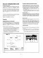
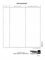
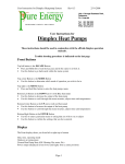
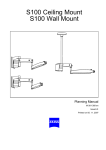
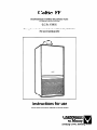
Celtic FF
ROOM SEALED FANNED BALANCED FLUE
COMBINATION BOILER
G.C. No. 47 980 01
This appliance has been tested and certificated by British Gas
(For use on natural gas only)
I
III
Ill
Instructions for use
(leave these instructions adjacent to the gas meter)
Looking Good. Heating Better
How your combination
Production
To isolate the heating circuit during the summer
boiler works
In some installations it is possible, after the boiler has been
operating continuously for a period providing hot water,
to get gravity circulation in the heating pipes. It will be
noticed that the pipes are getting hot and eventually the
first radiator will heat up. To avoid this, isolate as follows :
- Switch to ‘hot water only’ and close the valve (fig. 2 J) on
the heating flow.
- Do not forget to open the valve at the start of the heating season when the selector switch is set to ‘hot water
+ central heating’.
of hot water
This boiler is designed to give hot water at different temperatures and is fitted with a temperature selector
(fig. 1 FL
To obtain the hottest water turn the selector knob fully in
the ‘+’ direction. In this position the burner may cycle high
to low flame - this is normal. Greater amounts of cooler
water can be obtained by turning the selector knob towards the ‘-’ sign.
Pressure gauge (fig. 1 C)
Heating
This shows the water pressure in the central heating pipe
work. When cold it should read not less than 1 bar. This will
increase as the system heats up. A pressure relief valve
will operate at 3 bar. Your installer will be able to repressurise the system if necessary.
The boiler is automatically self adjusting when on central
heating. It is normal for the boiler to stay alight for extended periods with the flame height reduced.
The gas will be at high flame when the maximum output is
required, in cold weather or on start up.
Selector switch
When set for hot water only (position ‘I’) the boiler will only
operate on demand for hot water.
When set to hot water + central heating (position ‘II’) the
boiler will supply your central heating requirements but
will give priority to hot water demands. The central heating supply will be temporarily interrupted when drawing
hot water but this will have no noticeable effect on the
heating levels for normal quantities of hot water supply.
Controls
Installation
without
a room thermostat
Set the boiler thermostat (fig. 1 B) as required depending
on the desired room temperature. To increase the heat
turn to ‘+‘, to reduce the heat turn to ‘-‘. The temperature
gauge (fig. 1 E) indicates the temperature of the water
going to the radiators.
Installation
lighting
with a room thermostat
the boiler
I) Switch on the electricity.
2) Turn the lever on the gas service tap to the left
(fig. 2 G).
3) Set the selector switch (fig. 1 A) to required position.
For hot water only ‘I’ or for hot water + central heating
- Set the control on the room thermostat to the desired
temperature which will automatically control the firing
of the boiler to give the chosen room temperature.
- During cold weather, the boiler thermostat (fig. 1 B)
should be left on maximum, turned to position ‘+‘.
- In mild weather jt is recommended that the thermostat
is placed in an intermediate position.
‘II’.
The fan will start up and the pump will run if set to hot
water + central heating ‘II’.
Fig. 1
2
4) Press the igniter button (fig. 1 D) fully in.
- The fan will change to high speed to purge the combustion chamber, and the pump will stop.
- After approximately 14 seconds the spark generator
creates a continuous spark to light the pilot.
- When the pilot is alight, viewed through the sight
glass, wait a further 5 seconds before slowly releasing the button.
- If the pilot goes out wait at least 3 minutes and repeat as above.
5) If set to hot water + central heating ‘II’, check that the
flow isolating valve (fig. 2 J) is fully open (turn anticlockwise).
To turnofftheboiler
Set the selector switch to the centre position off ‘0’. Turn
off the gas by turning the lever (fig. 2 G) on the gas service tap to the right. Turn off the electricity supply.
To turn off the boiler leaving the pilot alight
Set the selector switch (fig. 1 A) to hot water only position
‘I’ turn off domestic water tap (fig. 2 H) under the appliance
and leave electricity supply on.
‘Gas leaks or faults’
If a gas leak or fau!t is suspected, turn off the appliance
and consult your local Gas Region or Service Engineer.
Clearances around your combination
boiler
These minimum clearances must be maintained for operation and servicing.
Top above Air Inlet Duct 50 mm (2 in)
200 mm (8 in)
Bottom Below Case
100 mm (4 in)
Sides
600 mm (24 in)
Front
‘Warning’
If the pilot is extinguished for any reason wait at least 3
minutes before attempting to relight.
Electrical
connections
The electrical supply connection must be made to a 240 V
50 Hz supply. The appliance must be protected by a 3 A
fuse. If a plug (BS 1363) is used or anv other type a 3 A
fuse must be fitted in the circuit.
Frost precautions
Providing the boiler is not isolated from the electricity supply it has automatic protection from damage bv frost.
This appliance must be earthed
To connect a plug
Overheating
If the pilot light or gas flame should go out whilst the boiler is set to operate :
- Wait 3 minutes before relighting.
If the boiler goes out again this may be due to the overheat safety device operating.
- If this persists contact your service engineer.
Cleaning
The surface of the boiler may be cleaned using soap,
water and a soft cloth or a non-abrasive cleaner.
Service
To ensure that the appliance continues to work efficiently
and has a long life, it is important that it is serviced annually.
Ask your installer or local Gas Region for details of a
regular service scheme.
This appliance is suitable for use with most showers and
automatic washing machines.
Gas safety
(INSTALLATION AND USE)
REGULATIONS 1984
In your own interest and that of safety, it is the law that
all gas appliances are installed by competent persons in
accordance with the Gas Safety Installation and Use Regulations 1984. If the appliance is installed in a compartment,
do not obstruct any purpose provided ventilation openings,
and do not use for storage purposes.
As the colour coding of the wires in the mains feed of the
appliance may not correspond with the colour marking
identification of your plug, proceed as follows :
- The wire which is coloured green/yellow must be
connected to the terminal in the plug marked with the
letter ‘E’ or by the earth symbol & or coloured green
or green and yellow.
- The wire which is coloured blue must be connected to
the terminal which is marked with the letter ‘N’ or
coloured black.
- The wire which is coloured brown must be connected to
the terminal marked ‘L’ or coloured red.
SERVICE RECORD
Date
Work Carried Out
Name of Service Company
55 A-Imp.
Chaffoteaux
CM. . Ref. 92120421
.07/88
et Maury Limited,
Trench Lock, Trench, Telford, Shropshire TFl 4SZ
Telephone : Telford (0952) 222727 - Telefax : (0952) 243493
LooMng~-Heatfng-
ESP305