1
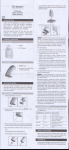
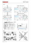
STERLING FF
Room Sealed Fanned Balanced
Flue Combination
Boiler
--- FOR USE ON NATURAL GAS ONLY
--
INSTRUCTIONS
--.----
--. .-.
FOR USE
HOWYOUR COMBINA~ON BOILERWORKS;
AS SAFETY ~INSTALL?UION
AND USE) REGULIWONS
In your own lnteresl and that of safety, it is the law that all gas appliances are installed by competent
persons ln accordance with the Gas Safety installation and Use Regulations. If the appliance is tnstalled
in a compartment, do not obstruct any purpose provided ventilation openings, and do not vse for
storage pqposes.
PLThe electrical supply connection must be made to a 240V 5OHz supply. The appliance must be
pro!ected by a 3 A fuse, if a 13A plug (BS 1363) is used or any 0the.rtype, a 3A fuse must be fitted in
the circuit.
IO CONNECT A PLUG
PRODUCTION OF HOT WATER
This boiler is designed to give hot water at constant temperature and is titted with a water regulator screw
(S) (Fig. 2). This regulator is adjusted and set at the time of instauation by the installer.
The boUer is automaticaUy self adjusting when on central heating. It is nomal for the boiler to stay aUght for
extended periods with tlame height reduced.
The gas wiU be at high flame when the maximum output is required, in cold weather or on start up.
When the appliance is connected to a ve.rtkxl Ilue, the temperature adjustment must not be set below the
midway position.
TO TURN OFF THE BOILER
Set the selector switch (A) to the centre position off (0) (see frg. 1). Turn off the electricity supply.
As the colour coding of the wires in the mains feed of the appliance may not correspond with the colour
making indentification of your plug, proceed as foUows :
- the wire which is coloured greemellow must be connected to the teminal in the plug marked with
the letter E or h the earth symbol -& or coloured green, greer@eUow.
~ the wire which 1scoloured blue must be connected to the terminal which is marked with the letter N
or coloured black.
- the wire which is coloured brown must be connected to the terminal marked L or coloured red
ITY FAULT
If the red indicator L.E.D. is alight, wait for 1 minute, then press on the manual reset button (F) (Fig. 1).
The burner will relight.
Should the problem persist, a fault is indicated. Turn off and contact your instaUeror your local Chaffoteaux
et Maury service center.
IO LIGHT THE BOILER
CLEANING
t)Switch on the electricity supply and ensure the gas (see G, Fig. 2) is turned on,
2) Set boiler temperature to maximum (see B, Fig. 1).
3) Set the selector switch (A) (Fig. 1) to the required position. To the left for hot water only or to the right
for hot water + central heating.
l When the selector switch is set on the hot water position, the boiler will fire automatically when
the hot water tap is open.
l If the selector switch is on hot water + central heating position, ensure that any ancUlav controls
and the boiler time switch are in demand position, the boiler wiU fxe automatkaly on central
heating and hot water accordlngty.
The case surface of the boiler may be cleaned using soap, water and a damp ctoth or non-abrasive cleaner.
SERVICING
To ensure that the appliance continues to work efficiently and has a tong Ufe,it is important that it is
servtced annuaUy by a competant person. &k your instaUeror Gas Regton for details of a regular service
scheme or contact your Chaffoteaux et Maury regional service center
If a gas leak or fault is suspected, turn off the appliance and consult your local Gas Region or contact your
local Chaffoteaux et Maury service center.
!XThese minimum clearances must be maintened for operation and servicing.
Top above air inlet duct
Bottom below case
~-.
Fig. 1
5omm (2in)
Sides
1OOmm(4in)
15Omm (6in)
Front
6COmm (24in)
GUARANTEE
Your STERLING domesttc holler 1stilly Guaranteedfor a period of one year ti-om
the date of purchase. Should a problem occur, Chaffoteaux et Maury LhnIted ~111
supply and fit any component free of charge, provldlng that the malfimctton ts the
result of faulty manufacture.
. .Fig. 2
- !%I the boiler themostat (l3) (Ftg. 1) as required depwding on the de&red room temperature. To krease
the heat turn to “+“, to reduce the heat turn to “-‘I. The temperature gauge indicates the temperature of the
water going to the radiators.
XNSTALXAIION
WXTE A ROOM TEERMOSIAT
- Set the control on the room thermostat to the desired tempetature and this will automatically control the
fling of the boiler to give the set room tmpetature.
In some instaUations it is possibIe, aIter the boiIer has been operaffng cor$inuousIy for a period providing
hot water, to get gavity circulation in the heating pipes. It wilI be noticed that the pipes are getting hot and
eventuaUy the first radiator will heat up. To avoid thk, isolate as follows :
- Switch to “hot water or@” and close the valve (J) (Fig. 2) on the heating flow,
- Do not forget to open the vaIve at the start of the heating season when the seIecior is set to “hot water +
central heating”
PRESSURE GAUGE KHFip.
11
This shows the water pressure In the central heating system. When coId it should rad no less than .8 bar.
This wiI1 increase as tfle system heats up. A pressure relief valve wiU opxate at 3.0 bat. Your inst?ller wiII
be ak4e lo re pressurise the system if necessary.
When set for hot water onb (to the lefl ) the boiler will only operate on demand for hot water.
When set for hot water + central heating (to right ) the boiler wiIl supply yotx central heating requirements
but wilI give priority lo hot water demands. The central heating suppty ~41 be temporarly interrupted when
drawing hot water but this will have no noticeable effect on the heating levels for normal quantities of hot
water suppIy.
SERVICE RECORD
Date
Work Carried Out
I
I
ESP306
I
Name of SenAce Company
Clld
1
et Mauq Limited,
etllIamy~&
Trench Lock, Trench, Telfoni, Shrwxh!nz TFl4SZ
.
Telephone : Telford (0952) 222727 - TelLfa : (0952) 243493 LOotig hod*Heaclng X5etter E
Chfloteaux