1
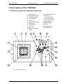
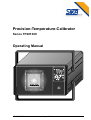
Precision-Temperature-Calibrator
Series TP281300
Operating Manual
3235004E.DOC
August 2009
1
SIKA TP281300
Operating manual
Table of Contents
Table of Contents
1
To this manual ........................................................................................................ 3
2
Safety ....................................................................................................................... 4
3
Description of the TP281300.................................................................................. 6
3.1
Modular groups and operating components............................................................................6
3.2
Design and function of the TP281300 .......................................................................................7
3.3
TP281300 standard units ............................................................................................................8
3.3.1
Sensor inputs.........................................................................................................................8
3.3.2
Mains cable ...........................................................................................................................8
3.3.3
Casing grab ...........................................................................................................................8
3.3.4
PC connection .......................................................................................................................8
3.3.5
PC terminal plann ................................................................................................................11
3.4
Accessories ...............................................................................................................................12
3.4.1
Transition cases ..................................................................................................................12
3.4.2
Software ..............................................................................................................................12
4
Transport, storage and starting the instrument................................................. 13
4.1
Transport....................................................................................................................................13
4.2
Storage .......................................................................................................................................13
4.3
Starting the instrument.............................................................................................................13
4.3.1
Proper use ...........................................................................................................................13
4.3.2
Expectable misuse ..............................................................................................................13
4.3.3
Positioning and connecting the TP281300..........................................................................14
5
Operating the TP281300 ....................................................................................... 15
5.1
Operating and setting up the TP281300..................................................................................15
5.1.1
Before starting the TP281300 .............................................................................................15
5.1.2
Establishing the Initial state.................................................................................................16
5.1.3
Starting the TP281300 ........................................................................................................16
5.1.4
Setting the testing temperature ...........................................................................................17
5.1.5
Block and sensor temperature stability ...............................................................................19
5.2
Connecting specimens .............................................................................................................20
5.2.1
Testing temperature switch .................................................................................................21
5.2.2
Testing thermocouples and resistance thermometers ........................................................23
5.3
6
Cooling down heating block ....................................................................................................24
Maintenance and Care.......................................................................................... 25
6.1
Care.............................................................................................................................................25
6.2
Maintenance...............................................................................................................................25
6.2.1
Recalibration........................................................................................................................25
6.2.2
Checking and exchanging the fuses ...................................................................................26
6.2.3
Recycling .............................................................................................................................28
7
Trouble shooting .................................................................................................. 29
8
Specification ......................................................................................................... 30
Appendix ...................................................................................................................... 34
Guideline DKD-R 5-4: Calibration of temperature block calibrators – Appendix B details of the DKD
technical committee's "Temperature and Humidity" for the operation of temperature block calibrators.
.............................................................................................................................................................34
3235004E.DOC
August 2009
2
SIKA TP281300
Operating manual
To this manual
1 To this manual
The SIKA-Precision-Temperature-Calibrator is an instrument
of the TP28000 series. This instrument is exactly a type
TP281300 one.
This user manual is focussed to skilled and semi-skilled
operators.
Before starting an operation carefully read through the
appropriate notes and follow the given sequence of
operations.
Read through chapter ‘Safety’ very thoroughly and exactly
remember the pictograms and their meanings.
The instrument is designed for the calibration of temperature
switches, thermostats, thermocouples, thermometers and
resistance thermometers.
This user manual is divided into eight chapters:
1.
General
2.
Safety
3.
Description of the TP281300
4.
Transport, storage and starting the instrument
5.
Operating the TP281300
6.
Maintenance and care
7.
Trouble shooting
8.
Specification
For any problems or questions possibly arising, please
contact your supplier or SIKA directly:
Dr. Siebert & Kühn GmbH & Co. KG
Struthweg 7-9 • D - 34260 Kaufungen
℡ 05605-803 0 • 05605-803 54
[email protected] • www.sika.net
3235004E.DOC
August 2009
3
SIKA TP281300
Operating manual
Safety
2 Safety
The TP281300 represents the state of the art. This applies to
measuring accuracy, functional principle and safe instrument
operation. Warranting safe operation, however, requires
expert and safety-reliable user attitude.
You will find the necessary notes in this chapter below.
Warnings, especially related to single operating processes or
manipulations, are given at the respective paragraphs of this
manual. These warnings are marked by the following
symbols:
Caution: High temperature!
This symbol refers to a situation being hazardous for
persons.
Danger! Injurious to Health!
This symbol refers to jeopardizing persons by electric
power.
Attention: Material damage!
This symbol refers to an action causing damages of the
instrument.
Note: This symbol stands for important notes.
The warning:
Attention! High temperature
is directly placed on the instrument as shown below:
Fig. 1: Magnification enlarge detail
3235004E.DOC
August 2009
4
SIKA TP281300
Operating manual
Safety
Specific safety notes
Note: The TP281300 has to be exclusively used for testing
temperature switches, thermostats, thermometers,
thermocouples, and resistance thermometers.
The TP281300 noise level is below 70 dbA.
Remove all easily flammable materials near the instrument
and prevent the instrument from contact with easily
flammable and explosive materials.
Always ensure sufficient cooling air supply by the built-in
fans. Do not hinder air supply by positioning the instrument
on a soft and yielding ground.
Connect the instrument to a circuit of low mains-breakdown
risk to avoid cooling air supply being stopped in case of
mains breakdown.
Take care to keep a distance of at least 1m from devices
which react sensitively to electromagnetic fields.
Ensure that transition cases and specimen are not
contaminated by media (e.g. oil) causing inflammation or
explosion in case of being heated up.
Test the actual heating block temperature before touching
the heating block or the transition casing since there is acute
danger of being burned.
Never remove transition cases from a heated heating block heated transition cases can cause inflammation.
Never remove specimen from a heated heating block - acute
danger of being burned.
Take note of the DKD technical committee's, "Temperature
and Humidity" details for the operation of temperature block
calibrators (see appendix).
Note:
Never leave a heated instrument without supervision.
3235004E.DOC
August 2009
5
SIKA TP281300
Operating manual
Description of the T281300
3 Description of the TP281300
3.1 Modular groups and operating components
1)
2)
3)
4)
5)
6)
7)
8)
9)
10)
Heating block
Heating block bore
Transition casing
Cycle display
Display
Mains switch on/off
Adjust key
Setpoint key
Start key
LED - temperature
switch
11) NO/NC toggle switch
12) Interface
(PC connection)
13) Ground Clamp for
specimen's shield
14) Input clamps
15) Rotary switch
16) Note
17) Latching knob
18) Protective grid
Fig. 2: TP281300 front panel
3235004E.DOC
August 2009
6
SIKA TP281300
Operating manual
Description of the T281300
3.2 Design and function of the TP281300
This precision temperature calibrator is operated by an
electronically controlled heating block and allowing to be
thermostated up to +1300 °C. The heating block has a bore
serving
as location hole for the specimen. An transition
casing
can be inserted in that bore. The casing serves
as an adapter between specimen (temperature switch,
thermostat,
thermocouple,
thermometer,
resistance
thermometer) and heating block bore. The heating block is
insulated against the housing.
Caution! The top side of the heating block is provided
with a protective grid
and an overheat warning.
The display
indicates - acc. to the position of rotary switch
- the temperature of the heating block or the specimen. It
is a 4 1/2-digit display with an accuracy of 0.5 K.
Set the desired heating block temperature by manipulating
the setpoint key
or the start key
. It is possible to set
the desired temperature with an accuracy of 0.5 K. The
adjust key
serves for controlling stable heating block
temperature levelling.
The input clamps
the instrument.
connect the specimen’s contacts with
The ground clamp
the instruments.
connects the specimen's shields with
The rotary switch
allows switching over between heating
block temperature and the temperature of the respective
specimen tested.
LED
and NO/NC toggle switch
testing temperature switches.
The RS 232C interface
to a computer.
3235004E.DOC
August 2009
are necessary for
is used to connect the instrument
7
SIKA TP281300
Operating manual
Description of the T281300
3.3 TP281300 standard units
3.3.1 Sensor inputs
The following test inputs are standard outfit:
B
Pt30%Rh/Pt16%Rh thermocouple,
Typ B (DIN EN 60584-1)
J
Fe/CuNi thermocouple,
Typ J (DIN EN 60584-1)
R
Pt13%Rh/Pt thermocouple,
Typ R (DIN EN 60584-1)
S
Pt10%Rh/Pt thermocouple,
Typ S (DIN EN 60584-1)
K
NiCr/NiAl thermocouple,
Typ K (DIN EN 60584-1)
Pt100
Pt100 resistance thermometer,
3-wire (DIN EN 60751)
Block Temp indicating the heating block temperature
Fig. 3 TP281300 rotary switch
3.3.2 Mains cable
A mains cable for power supply is enclosed to the
TP281300.
3.3.3 Casing grab
A grab for taking out the transition casing is enclosed to the
TP281300.
3.3.4 PC connection
A data transfer cable is enclosed to the instrument.
The TP281300 is provided with a RS 232C serial interface. It
is bidirectional, i.e. it is possible to transmit data for further
processing by a superior computer and to receive data for
programming the instrument by a superior computer as well.
3235004E.DOC
August 2009
8
SIKA TP281300
Operating manual
Description of the T281300
The transmitting mode continuously transmits a couple of
measuring values - the actual block temperature and the
temperature value displayed. The transmitting protocol has
16 bytes total. All information is transmitted in ASCII.
Transmitting protocol
Byte
0
1
2
3
4
5
6
7
8
9
10
11
12
13
14
15
Value
02
„B“
„+“, „-“
„!“
„0“ ... „9“
„0“ ... „9“
„0“ ... „9“
„0“ ... „9“
„0“ ... „9“
„B“
„P“
„K“
„S“
„R“
„J“
„A“
„+“, „-“
„!“
„0“ bis „9“
„0“ bis „9“
„0“ bis „9“
„0“ bis „9“
„0“ bis „9“
03
Explanation
STX (start of text, start of protocol)
The following bytes 2…7 show the information of the
block temperature
mathematical sign of the block temperature
invalid block temperature
103 digit, block temperature
102 digit, block temperature
101digit, block temperature
100digit, block temperature
10-1digit, block temperature
kind of sensor of the temperature displayed
Block temperature
Pt100
NiCr/NiAl
Pt10%Rh-Pt
Pt13%Rh-Pt
Fe/CuNi
Pt30%Rh-Pt16%Rh
mathematical sign of the sensor temperature
invalid sensor temperature
103 digit, sensor temperature
102 digit, sensor temperature
101 digit, sensor temperature
100digit, sensor temperature
10-1 digit, sensor temperature
ETX (end of text, end of protocol)
The transmitting parameters are adjusted to:
9600 baud, 8 data bits, 1 stop bit, odd parity.
3235004E.DOC
August 2009
9
SIKA TP281300
Operating manual
Description of the T281300
In the receiving mode the TP281300 can record data for the
control of those functions being also adjustable by the
setpoint and start keys. This means that a superior control
computer can set new required values and actuate
temperature switch test release. The receiving protocol has 9
bytes total. All information is received in ASCII.
Receiving protocol
Byte
Value
0
1
2
3
4
5
6
7
8
„0“ ...
„0“ ...
„0“ ...
„0“ ...
„0“ ...
02
„E“
„A“
„+“
„!“
„9“ or „X“
„9“ or „X“
„9“ or „X“
„9“ or „X“
„9“ or „X“
03
Explanation
STX (start of text, start of protocol)
release temperature switch test
block temperature switch test
sign required value
do not enter new required value
103 digit, required value
102 digit, required value
101 digit, required value
100 digit, required value
10-1 digit, required value
ETX (end of text, end of protocol)
The receiving parameters are adjusted to:
9600 baud, 8 data bits, 1 stop bit, odd parity
Superior control computer transmitting the byte sequence:
Byte
0
1
2
Value
02
„!“
03
Explanation
STX (Start of Text, start of protocol)
transmit parameters
ETX (end of text, end of protocol)
requests the TP281300 to transmit the stored information on
instrument type, required value and temperature switch state
to the control computer. The TP281300 replies this prompt
by singly transmitting the byte sequence:
Byte
Value
0
1 ... 7
8
9
10
11
12
13
14
15
16
02
„TP28130"
„S“
„+“, „-“
„0“ ... „9“
„0“ ... „9“
„0“ ... „9“
„0“ ... „9“
„0“ ... „9“
"T"
"0"
"1"
03
17
3235004E.DOC
Explanation
STX (start of text, start of protocol)
information on kind of instrument
stored required value
signs of stored required value
103 digit, stored required value
102 digit, stored required value
101 digit, stored required value
100 digit, stored required value
10-1 digit, stored required value
stored temperature switch state
temperature switch blocked
temperature switch released
ETX (end of text, end of protocol)
August 2009
10
SIKA TP281300
Operating manual
Description of the T281300
Inputs
Input level +/- 30 V max.
Low level: + 2.5 ... +30V
High level: -30 ... +0.8V
Input impedance: 3...7 K
RxD
Received data
CTS
Clear to send
Outputs
Output level +/- 9 V, +/- 5 V min.
Low level: + 5 V min.
High level: - 5 V min.
TxD
Transmitted Data
RTS
Request to send
3.3.5 PC terminal plann
Fig. 3: PC terminal plann
3235004E.DOC
August 2009
11
SIKA TP281300
Operating manual
Description of the T281300
3.4 Accessories
3.4.1 Transition cases
Transition casings are necessary to keep the differences in
temperature between the test piece and the heating block as
low as possible.
The 28mm diameter of the heating block borehole is reduced
to the size of the outer diameter of the test piece using the
transition casing.
Therefore, the bore hole of the transition casing may be
at most 0.5mm larger than the outer diameter of the test
piece within the temperature range of 400...660 °C,
and
at most 1.0mm within the range of 660...1300 °C.
The transitional casings can be supplied with an inner
diameter of 1.5...25mm in 0.5mm intervals.
The transition casings can be manufactured in various
designs, according to customer requirements. Transition
casings are also available with multiple bore holes.
3.4.2 Software
Efficient software is available for TP28000 series
instruments. This software allows the remote control of the
instrument by a PC and carrying out data acquisition and
evaluation.
3235004E.DOC
August 2009
12
Sika TP281300
Operating manual
Transport, storage and starting
4 Transport, storage and starting the instrument
4.1 Transport
The TP281300 testing instrument is a portable unit for
versatile service purposes as well as for industrial and
laboratory tasks. It is provided with a handle attached on its
side and being brought to any position by depressing the
lateral latching knobs
. For bearing the instrument bring
the handle into vertical position until handle locks.
Attention:
For transport, e.g. to recalibration, use original packing to
avoid any damage
4.2 Storage
Store the TP281300 dust-proof and at a dry place. The
ambient temperature between -10 °C and +80 °C during
storage has to be warranted.
4.3 Starting the instrument
4.3.1 Proper use
Use the TP281300 exclusively for testing temperature
switches, thermostats, thermocouples, thermometers and
resistance thermometers within the given temperature range.
4.3.2 Expectable misuse
Ensure that the testing temperature is suitable for the
specimen to prevent the specimen from being destroyed.
Caution: Remove all easily flammable media from the
surrounding of the instrument and prevent the
instrument from contact with easily flammable and
explosive materials
3235004E.DOC
August 2009
13
Sika TP281300
Operating manual
Starting the instrument
4.3.3 Positioning and connecting the TP281300
Check-ups before starting
Attention: When positioning the instrument ensure that the
fan in the instrument’s bottom can supply enough air. Do
not position the instrument on a soft and yielding ground.
Attention: When installing the TP281300, take care to
keep a distance of at least 1m from devices which react
sensitively to electromagnetic fields.
Before starting bring the instrument in its normal operating
position.
Procedure:
•
Always position the TP281300 in vertical position.
•
If the TP281300 is not being vertically positioned an
even temperature distribution within the heating block is
not warranted.
•
Check specifications.
•
Compare the label with specification.
Caution:
Check the heating block bores for being clean and
undamaged. Do not use filling media.
Check for:
• the specimen
• the transition casing
• the heating block bore
exactly matching to each other.
•
Keep the thermal contact resistance as low as possible.
Connect the instrument to a circuit of low mains breakdown
risk to avoid cooling air supply stoppage in case of mains
breakdown.
Check for:
•
the fan starting operation when being connected to the
mains.
Take note of the DKD technical committee's, "Temperature
and Humidity" details for the operation of temperature block
calibrators (see appendix).
3235004E.DOC
August 2009
14
Sika TP281300
Operating manual
Operating the TP281300
5 Operating the TP281300
5.1 Operating and setting up the TP281300
5.1.1 Before starting the TP281300
Select place
Position the TP281300 so that there is enough space for the
fan in the instrument’s base to produce sufficient cooling air.
Otherwise, insufficient cooling causes damage and destructs
the instrument.
Take care to keep a distance of at least 1m from devices
which react sensitively to electromagnetic fields.
Note:
Put the TP281300 into vertical position for calibrating to
warrant optimal temperature spreading and transmission.
You can vary the position of the TP281300 carrying handle
by depressing the grey pushbuttons in it’s rotary joint.
Ground state before switching on
Turn rotary switch into position „BlockTemp“.
Fig. 4 Rotary switch ground position
3235004E.DOC
August 2009
15
Sika TP281300
Operating manual
Operating the TP281300
5.1.2 Establishing the Initial state
To clear all stored values of the TP281300 , you can set the
instrument to a defined initial state.
Procedure:
1.
Apply mains voltage.
The fan in the instrument’s base begins to operate.
2.
Depress setpoint key and keep it depressed.
3.
Turn mains switch into EIN (ON) „I“.
4.
Release setpoint key.
5.
For some seconds "CAL" appears on the display
(Calibration of the built-in electronic).
6.
You hear a click with „StOP“ appearing on the display.
The fan steps into the second stage
7.
Depress start key.
5.1.3 Starting the TP281300
The testing temperature set last remains stored in the
TP281300. After starting the TP281300 the temperature of
the heating block rises up to that one stored.
Procedure:
1.
Apply mains voltage.
The fan in the instrument’s base begins to operate.
2.
Turn mains switch into EIN (ON) „I“.
3.
For some seconds "CAL" appears on the display
(Calibration of the built-in electronic) and then "StOP".
4.
You hear a click with „StOP“ appearing on the display.
The fan steps into the second stage.
5.
Depress start key.
The heating block is now heated up to the testing
temperature set last.
6.
Turn rotary switch into position „BlockTemp“.
The actual temperature of the heating block is displayed.
7.
Depress setpoint key.
Flashing „SOLL“ is displayed.
8.
Depress start key.
Flashing required temperature (testing temperature) is
displayed.
Note: For changing the set testing temperature - see
paragraph 5.1.4 „Setting the testing temperature“.
3235004E.DOC
August 2009
16
Sika TP281300
Operating manual
Operating the TP281300
5.1.4 Setting the testing temperature
Set new testing temperature as described below.
With the aid of the setpoint and start keys you can set the
testing temperature with an accuracy of 1/10 K.
The temperature is displayed in 0,5 °C intervals.
Procedure:
1.
Apply mains voltage.
2.
Turn mains switch into EIN (ON) „I“.
3.
Turn rotary switch into „BlockTemp“.
Note: Undepressed key for approx. 30 sec stops
programming for safety reasons and resets the instrument
on „StOP“. Then you have to start the instrument again see paragraph „Starting the TP281300 “).
4.
Depress start key.
5.
Depress setpoint key.
Testing temperature set is displayed.
6.
Depress start key again.
Flashing 1/10-digit of testing temperature is displayed.
7.
Depress start key frequently until the desired 1/10-value
is displayed.
8.
Depress setpoint key.
1/10-digit confirmed, flashing unit place is displayed.
9.
Depress start key frequently until desired unit place is
displayed.
10. Depress setpoint key.
Unit place confirmed, flashing ten’s place is displayed.
11. Depress start key frequently until desired ten’s place is
displayed.
12. Depress setpoint key.
Ten’s place confirmed, flashing hundred’s place is
displayed.
13. Depress start key frequently until desired hundred’s
place is displayed.
14. Depress setpoint key.
Hundred’s place confirmed, flashing thousand’s place is
displayed.
3235004E.DOC
August 2009
17
Sika TP281300
Operating manual
Operating the TP281300
15. Depress start key frequently until desired thousand’s
place is displayed.
16. Depress setpoint key.
Thousand’s place confirmed, flashing „SoFF“ is
displayed.
17. Depress setpoint key again.
The actual heating block temperature is displayed.
18. The heating block is heated up to the set testing
temperature.
Note: During programming it is important that the desired
set value is within the temperature range 400,0 and
1300,0 °C. Set values outside of this range will be
interpreted as an error from the fitted micro-processor and
the error message "Err" is displayed. After pressing the
"Start"-key a correct set value must be programmed.
Note:
If the instrument should be cooled down to ambient
temperature, the set value "000.0" must be programmed.
Fine balancing of the testing temperature
After having programmed the TP281300 for a new required
value, the heating block is heated up or cooled down to the
new temperature. For reasons of external interference it can
happen that the heating block does not directly attain the
testing temperature set. This would mean a difference
between the required temperature (testing temperature) and
the actual one displayed. The TP281300 , however, has an
automatic adjusting function serving for automatic difference
balancing. The incorporated microprocessor is continuously
calculating the actual-/required-value difference and thus
controlling the heating block.
Fine balancing is useful, only after heating block temperature
control levelled out on the final temperature value level. The
microprocessor checks for calling up fine balancing.
The microprocessor does fine balancing with the following
fine balancing preconditions fulfilled:
1.
Actual heating block temperature deviation from set
testing temperature not more than ± 25K.
2.
Actual heating block temperature does no longer vary
(constant temperature displayed).
With the aid of the adjust key you can check for the fine
balancing already done by the microprocessor.
3235004E.DOC
August 2009
18
Sika TP281300
Operating manual
Operating the TP281300
Procedure:
1.
Depress adjust key.
2.
Flashing „Adj“ is displayed when the heating block
temperature is levelled out. If the display remains dark
the heating block temperature isn’t still levelled out.
3.
Wait for some minutes, then carry out the test a second
time.
4.
Depress adjust key again.
5.
The temperature of the heating block is displayed.
5.1.5 Block and sensor temperature stability
Block temperature stability
As long as the heating block temperature display is flashing
the heating block isn’t still levelled out on the set required
value. In case of constant heating block temperature display
the temperature is on the set level.
The microprocessor checks up the following heating block
stable temperature criteria:
1.
Actual heating block temperature does no longer vary
(constant temperature displayed).
2.
The difference between programmed actual and
required temperature value is less than 0.5 K.
Sensor temperature stability
Turn rotary switch into the symbol for the temperature sensor
connected.
Flashing sensor temperature display means a still varying
one. With the final sensor temperature level being attained
sensor temperature is constantly displayed.
3235004E.DOC
August 2009
19
Sika TP281300
Operating manual
Operating the TP281300
5.2 Connecting specimens
Attention:
Connect specimens acc. to their specification
Connect the specimens shield to the ground clamp.
Different specimens can be calibrated:
• thermometers
•
•
•
•
temperature switches
thermostats
thermocouples
resistance thermometers
Insert the thermometer into the appropriate transition casing.
Caution: Injurious to health - cracking thermometer.
Always observe the maximum temperature capacity of
the thermometer.
3235004E.DOC
•
Temperature switches and thermostats switching on or
off after having attained the temperature set.
Connect the temperature switch as shown below:
•
Thermocouples measuring an actual temperature:
•
3-wire circuited resistance thermometers measuring an
actual temperature.
Connect the resistance thermometer as shown below:
August 2009
20
Sika TP281300
Operating manual
•
Operating the TP281300
2-wire circuited resistance thermometers measuring an
actual temperature.
Connect the resistance thermometer as shown below:
5.2.1 Testing temperature switch
Caution:
Burning heat: Let the TP281300 cool down after use
(see paragraph „Cool down heating block“).
Note:
To obtain an exact measuring result the specimen has to
fit properly in the bore of the heating block or of the
transition casing.
Prerequisites for exact results:
• The outer diameter of the test piece
matches the inner diameter of the
bore hole
(--->Sect. 3.4.1 "Transition casings").
• The calibrating instrument is in
vertical position.
• Unbended specimen.
• Insert the specimen in dry state
directly into the bore of the heating
block or in that one of the appropriate
transition casing.
• The measuring element of the sensor
is located in the region of the
homogeneous zone* of the calibrator
heating block.
Note:
Before starting the measurement the specimen must have
obtained the temperature of the block.
Give the specimen enough time for coming up to the block
temperature level.
3235004E.DOC
August 2009
21
Sika TP281300
Operating manual
Operating the TP281300
Procedure:
1.
Turn rotary switch into position „BlockTemp“.
2.
A temperature switch can open or close when reaching
the test temperature.
• For testing a closer set toggle switch on position
„NO“.
• For testing an opener set toggle switch on position
„NC“.
3.
Set test temperature of the heating block
(see pragraph „Setting the test temperature“).
4.
Depress setpoint key.
Flashing „SOLL“ is displayed.
5.
Depress setpoint key again.
Flashing „SOFF“ (SOFF = switch: off) is displayed.
6.
Depress start key.
Flashing „SON“ (SON = switch: on) is displayed.
7.
Depress setpoint key.
Actual heating block temperature is displayed.
8.
The specimen switches (closes or opens) when the
resp. test temperature is attained.
• The calibrating instrument indicates the switching of
the specimen
by the green LED and by an acoustic signal.
To finish temperature switch testing heating block the testing
function as follows:
3235004E.DOC
1.
Depress setpoint key.
Flashing „SoLL“ is displayed.
2.
Again depress setpoint key.
Flashing „SoFF“ (SoFF = switch: off) is displayed.
3.
For input confirmation: Depress setpoint key.
Actual heating block temperature is displayed.
August 2009
22
Sika TP281300
Operating manual
Operating the TP281300
5.2.2 Testing thermocouples and resistance thermometers
Caution:
Burning heat: Let the TP281300 cool down after use
(see paragraph „Cool down heating block“).
Note:
To obtain an exact measuring result the specimen has to
fit properly in the bore of the heating block or of the
transition casing.
Caution:
Burning heat around the specimen’s diameter. The
specimen adapts the heating block temperature which
can be up to 1300 °C. Remove specimen only after
complete cooling-down of the heating block.
Prerequisites for exact results:
• The outer diameter of the test piece
matches the inner diameter of the
bore hole
(--->Sect. 3.4.1 "Transition casings").
• The calibrating instrument is in
vertical position.
• Unbended specimen.
• Insert the specimen in dry state
directly into the bore of the heating
block or in that one of the appropriate
transition casing.
• The measuring element of the sensor
is located in the region of the
homogeneous zone* of the calibrator
heating block.
Note:
Before starting the measurement the specimen must have
obtained the temperature of the heating block.
Give the specimen enough time for coming up to the heating
block temperature level.
Procedure:
1. Turn rotary switch into position „BlockTemp“.
2. Clamp specimen.
3. Check kind of sensor.
The following sensors can be chosen:
B
Switch setting
Pt30%Rh/Pt16%Rh thermocouple, Typ B
(DIN EN 60584-1)
J
Fe/CuNi thermocouple, Typ J
(DIN EN 60584-1)
3235004E.DOC
August 2009
23
Sika TP281300
Operating manual
R
Operating the TP281300
Pt13%Rh/Pt thermocouple, Typ R
(DIN EN 60584-1)
S
Pt10%Rh/Pt thermocouple, Typ S
(DIN EN 60584-1)
K
NiCr/NiAl thermocouple, Typ K
Pt100
Pt100 resistance thermometer, 3-wire
(DIN EN 60584-1)
(DIN EN 60751)
Block Temp indicating the heating block temperature
4.
Turn rotary switch into the respective position.
The temperature measured by the specimen is
displayed.
5.
Turn rotary switch into position „BlockTemp“.
Actual heating block temperature is displayed.
6.
Compare heating block temperature with the
temperature display of the specimen.
5.3 Cooling down heating block
Caution:
Burning heat. Let the TP281300 cool down after use.
Transport the TP281300 only after being completely cooled
down.
Burning heat on the heating block’s surface.
Burning heat at specimen.
Never touch heating block or specimen surface.
Never leave the TP281300 unobserved after use.
Wait until the heating block has attained
temperature before packing the TP281300.
ambient
It is possible to enhance cooling by zeroing the test
temperature (see pragraph „Setting the test temperature“).
Remove transition cases.
Caution:
Burning heat. The transition cases can be heated up
to 1300 °C. Only remove the cases in cooled state.
3235004E.DOC
1.
Compress supplied casing grabs and fit into the
transition casing bores.
2.
Remove transition casing.
August 2009
24
Sika TP281300
Operating manual
Maintenance and care
6 Maintenance and Care
6.1 Care
Attention:
Always keep the TP281300 clean and do not leave it in
dusty and moisty rooms.
Clean the TP281300 after each use.
Attention:
Avoid measuring errors by always keeping the heating
block bores clean and never using filling media for
measuring.
6.2 Maintenance
When switching on your TP281300 is not possible check the
fuses and exchange, if necessary.
Fuses inside the TP281300 housing.
Danger:
Electric voltage.
Before exchanging the fuses disconnect mains plug.
Check the fuses
(see pragraph „Checking and exchanging the fuses“).
Exchange fuse in case of defect.
6.2.1 Recalibration
The TP281300 is adjusted and tested by the manufacturer
acc. to the accepted standards.
On the basis of the DIN ISO 10 012 standard the TP281300
has to undergo testing within fixed intervals of time.
Note:
Use original packing to mail the TP281300.
Therefore, we recommend to send the TP281300 to our
factory for recalibration or readjustment within intervals of at
maximum 12 months or after 500 operating hours.
3235004E.DOC
August 2009
25
Sika TP281300
Operating manual
Maintenance and care
6.2.2 Checking and exchanging the fuses
The TP281300 is equipped with two fuses which have to be
checked and exchanged, if necessary.
1. Mains unit fuse
Check the fuse at mains input when switching on the
TP281300 and
• in case the fan does not start, or
• nothing appears on display.
Procedure:
Danger:
Electric voltage, injurious to health.
Before exchanging the fuses, disconnect mains plug.
1.
Disconnect mains plug.
2.
Put instrument’s topside down.
3.
Pull out mains cable.
4.
Using a screw-driver turn out mains cable cap.
5.
Remove cap.
Now fuse (T6.3 250V) is visible.
6.
Check fuse.
Warning: avoid the destruction of the TP281300.
Only use fuses with the values of T6,3 250V (6,3A delay
action, 250VAC).
3235004E.DOC
7.
In case of defect fuse can be exchanged for spare one
in the cap.
8.
Exchange fuse and refix cap.
August 2009
26
Sika TP281300
Operating manual
Maintenance and care
2. Electronics fuse
Check electronics fuse when switching on the TP281300 and
nothing appears on display.
Procedure:
Danger:
Electric voltage, injurious to health.
Before exchanging the fuses, disconnect mains plug.
1. Disconnect mains plug.
2. Loosen all four screws on front plate.
Fig. 5: Electronics unit front plate
Note: Stiff plug-and-socket connection of electronics unit.
3. Slowly pull electronics unit c upward until electronics is
disconnected
Fig. 6: Removing electronics unit
3235004E.DOC
August 2009
27
Sika TP281300
Operating manual
Maintenance and care
4. Remove electronics unit and reverse.
Fuse position is now visible.
Fig. 7: Back of the electronics unit
5. Screw out fuse and check.
6. In case of defect fuse always insert a new T40 250 V
(40 mA slow, 250 VAC) one.
7. Screw in fuse.
Note:
Insert electronics unit c together with guide plate dinto
guide bar.
8. Insert electronics and tighten.
6.2.3 Recycling
SIKA factory guarantees for expert recycling.
Therefore return the TP281300 free of charge.
3235004E.DOC
August 2009
28
Sika TP281300
Operating manual
Trouble shooting
7 Trouble shooting
Note:
This table shows how to carry out trouble shooting.
Trouble
TP281300 not in proper
function.
Cause
External influence, e.g. magnetic fields, incorrect supply
voltage.
Remedy
Test applied mains voltage
and compare to that one given
on the label.
Disconnect mains plug.
Check fuses and exchange in
case of defect.
Nonsensical symbols and
values displayed.
-/-
Set instrument into ground
state (see par. 5.1.2).
TP281300 goes into standby.
„StOP“ is displayed.
Adjust, setpoint or start keys
were depressed.
Display zeigt: „ERR“
Programming not finished.
Again depress start key, then
TP281300 starts measuring
procedure.
TP281300 goes into error
position.
„Err“ is displayed.
Wrong testing temperature
programmed.
Depress start key and repeat
entry.
TP281300 goes into error
position.
Internal heating block sensor
defect.
Heating block sensor
exchange at the manufacturer.
Failure of the internal block
sensor.
Heating block sensor
exchange at the manufacturer.
Automatic switch off when
controls overshoot.
Let instrument cool down. The
control system will turn back
on at < 1300 °C.
If needed, initially approach a
lower control input.
The heating block heats up to
a temperature of approx.
1330 °C.
Let instrument cool down.
A factory inspection is
necessary if the error occurs
again.
„Err“ is displayed.
The heating block heats up to a
temperature of approx.
1315 °C.
The TP281300 switches the
stabiliser off
Display shows "ERR"
The entire heating circuit is
switched off by a temperature
fuse.
Note:
In case the instrument is still in inproper function after the
above trouble shooting it has to be checked at the
manufacturer.
3235004E.DOC
August 2009
29
Sika TP281300
Operating manual
Specification
8 Specification
Setting the heating block temperature:
by required value programming
check by „Adjust“ function between 400,0°C and 1300,0 °C
Heating times:
Changing
temperature
Heating-up time *)
400°C to 1300°C
90 min
400°C to 600°C
90 min
600°C to 800°C
80 min
800°C to 1000°C
75 min
1000°C to 1200°C
70 min
*) It is necessary to factor in an additional 30 minutes of adjustment time
Cooling times:
Changing
temperature
Cooling times *)
1300°C to 1000°C
20 min
1000°C to 800°C
20 min
800°C to 600°C
30 min
600°C to 400°C
50 min
*) It is necessary to factor in an additional 30 minutes of adjustment time
Heating block temperature balancing:
400 … 1300 °C with 0,5 K resolution
Heating block control accuracy:
±2K
Heating block control stability:
± 0,5 K
Heating block control / Measuring element in heating block:
PID-controller / Pt10%RH-Pt with automatic cold-junction
compensation for environmental temperatures between 0°C
and 60°C.
3235004E.DOC
August 2009
30
Sika TP281300
Operating manual
Specification
Actual value display:
4 ½ -digit / 7-segment LED of 14 mm heigt
Exceeding range / sensor break:
„-OFLO“/„OFLO“ display
Sensor break for control unit:
Heating voltage switched off, „ERR“ displayed
Temperature safety system in case of exceeding limit:
2 independently operating safety devices by
approx. 1315 °C und 1330 °C, heating voltage switched off
Power supply / power consumption:
230 V, 50/60 Hz, ca. 1200 VA
(optionally): 115 V, 50/60 Hz, ca. 1200 VA
Heating block bores:
TP281300/28/200: depth 200 mm,
diameter Ø 28 mm
Transition casing bore:
TP281300/28/200:
The transition casings can be supplied with an inner
diameter from d 1.5...25mm in 0.5mm intervals.
Special transition casings can be manufactured in various
designs according to customer requirements. Transition
casings are also available with multiple bore holes.
3235004E.DOC
August 2009
31
Sika TP281300
Operating manual
Specification
Temperature sensor inputs:
Pt100, 2- or 3-wire acc. to DIN EN 60751
NiCr/NiAl, K type acc. to DIN EN 60584-1
Pt10%Rh/Pt, S type acc. to DIN EN 60584-1
Pt13%Rh/Pt, R type acc. to DIN EN 60584-1
Fe/CuNi, J type acc. to DIN EN 60584-1
Pt30%Rh/Pt6%Rh, B type acc. to DIN EN 60584-1
Resolution and measuring inaccuracy of the measuring instrument for external sensors
(test pieces):
Pt100 (DIN EN 60751), 3-wire:
-90,0 bis +200,0 °C: ± 0,1 % f.s. ± 0,5 °C
+200,0 bis
+850,0 °C: ± 0,1 % f.s. ± 0,5 °C
NiCr/NiAl (DIN EN 60584-1):
-90,0 bis +200,0 °C: ± 0,1 % f.s. ± 0,5 °C
+200,0 bis +1370,0 °C: ± 0,1 % f.s. ± 0,5 °C
Pt10%Rh/Pt (DIN EN 60584-1):
0,0 bis +200,0 °C: ± 0,2 % f.s. ± 0,5 °C
+200,0 bis +1760,0 °C: ± 0,2 % f.s. ± 0,5 °C
Fe/CuNi (DIN EN 60584-1
-90,0 bis +200,0 °C: ± 0,1 % f.s. ± 0,5 °C
+ 200,0 bis
+900,0 °C: ± 0,1 % f.s. ± 0,5 °C
Pt13%Rh/Pt (DIN EN 60584-1):
0,0 bis +200,0 °C: ± 0,2 % f.s. ± 0,5 °C
+200,0 bis +1760,0 °C: ± 0,2 % f.s. ± 0,5 °C
Pt30%Rh/Pt6%Rh (DIN EN 60584-1):
+100,0 bis +1820,0 °C: ± 0,2 % f.s. ± 0,5 °C
Cold junction compensation:
built-in for ambient temperatures between 0 and 60 °C
Digital interface:
Connector: D-Sub DB09
RS232C, transmitting scheme:
9600 baud, 8 data bit, 1 stop bit, odd parity
3235004E.DOC
August 2009
32
Sika TP281300
Operating manual
Specification
Dimensions and weight:
Dimensions
length,
total / of instrumen
total width
total height,
incl. handle and
cable hairness
weight
3235004E.DOC
August 2009
TP281300/28/200
520/480 mm
280 mm
480/410 mm
ca. 30 kg
33
Sika TP281300
Operating manual
Appendix
Appendix
Guideline DKD-R 5-4: Calibration of temperature block calibrators – Appendix B
details of the DKD technical committee's "Temperature and Humidity" for the
operation of temperature block calibrators.
Having a calibrator certificate from a DKD calibrator laboratory confirms that the temperature block
calibrator meets the high demands of the calibrating ability of such a device, which are outlined in the
guidelines DKD-R 5-4. Nevertheless, the following points should be noted regarding the use of the
calibrator:
The calibration of the temperature block calibrator predominantly relates to the temperature of the solid
body block. The temperature of the thermometer in the block to be calibrated can differ from this
temperature. If a thermometer of the same model, under the same test conditions as were used in the
calibration is used, it can be assumed that the measurement difference in the calibration of ideal
thermometers are not larger than the measurement inaccuracy which is stated in the calibrator certificate.
If it is the case that nothing else is specified on the calibrator certificate, it must be ensured that
•
the measuring element is located in the homogeneous temperature zone.
•
The inner diameter of the bore hole used in the calibrator (possibly the casing) in the temperature
range of –80 °C to 660 °C is a maximum of 0.5mm bigger than the outer diameter of the
calibrated thermometer, and in the temperature range of 660 °C to 1300 °C is a maximum of
1.0mm bigger
•
The immersion depth of the thermometer to be calibrated amounts to at least 15 times the outer
diameter of the thermometer to be calibrated
•
The thermometer to be calibrated has an outer diameter of d < 6 mm.
Please take particular care if a heat transfer medium was used during the calibration of the temperature
block calibrator. If this is the case the calibration is only effective if the calibrator was used with a
corresponding heat transfer medium.
With the calibration of thermometers with an outer diameter d > 6 mm allow for an additional error of
measurement due to heat conduction. In the case that such measurements are required, the additional
heat conduction can be determined by the thermometer model and ascertained from your DKD calibrator
laboratory. A good test of the possible temperature variations caused by heat conduction consists of
testing whether the display of the calibrated thermometer changes when it is lifted 20mm. Contributions to
measurement inaccuracy that are conditional on the thermometer to be calibrated (e.g. inhomogeneities
from thermal elements), are likewise not covered in the measurement inaccuracy of the calibrator.
In the case that the calibrator is used in load conditions that do not comply with the load condition from
the calibration, the influence of the load condition can be determined through replacement or addition of
other thermometers on site.
The details on the calibration certificate are important for the calibration, not the manufacturers'
instructions. Before the calibration please make sure you agree upon the operation and calibration
conditions with your DKD calibration laboratory.
If there is nothing else specified on the calibrator certificate, (independent from the manufacturers'
instructions) it must be ensured that
•
the calibrator is used in a vertical position
•
no additional thermal isolation is in use
•
the environmental temperature is (23 + 5) °C.
In order to check the calibration of the temperature block calibrator it is recommended to take regular
measurements with a calibrated thermometer. If control measurements with a calibrated thermometer are
not taken annually, recalibration of the temperature block calibrator is strongly recommended.
© German calibration services • Accreditation body • Email:[email protected]• Website: www.dkd.eu
3235004E.DOC
August 2009
34