1
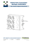
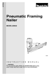
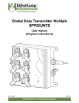
Precision-Temperature-Calibrator
Series TP28850E
User Manual
February 2001
Sika TP28850E
User Manual
Table of Contents
1 TO THIS USER MANUAL............................................................................................ 3
2 SAFETY ....................................................................................................................... 4
3 DESCRIPTION OF THE TP28850E ............................................................................. 6
3.1 Modular groups and operating components.................................................................. 6
3.2 Design and function of the TP28850E............................................................................. 7
3.3 TP28850E standard units ................................................................................................. 8
3.3.1 Mains cable ................................................................................................................. 8
3.3.3 Sleeve grab .................................................................................................................. 8
3.3.4 PC connection .............................................................................................................. 8
Transmitting protocol ............................................................................................................. 8
Receiving protocol ................................................................................................................. 9
3.3.4 PC terminal plan ......................................................................................................... 10
3.4 Special accessories ........................................................................................................ 10
3.4.1 Adapter sleeves.......................................................................................................... 10
3.4.2 Software ..................................................................................................................... 10
4 TRANSPORT, STORAGE AND STARTING THE INSTRUMENT ............................. 11
4.1 Transport ......................................................................................................................... 11
4.2 Storage............................................................................................................................. 11
4.3 Starting the instrument................................................................................................... 11
4.3.1 Proper use .................................................................................................................. 11
4.3.2 Expectable misuse ..................................................................................................... 11
4.3.3 Positioning and connecting the TP28850E ................................................................ 11
5 OPERATING THE TP28850E .................................................................................... 13
5.1 Operating and setting up the TP28850E ....................................................................... 13
5.1.1 Before starting the TP28850E .................................................................................... 13
5.1.3 Starting the TP28850E ............................................................................................... 13
5.1.4 Setting the testing temperature .................................................................................. 14
5.1.4 Block temperature stability ......................................................................................... 15
5.2 Cooling down heating block .......................................................................................... 15
6 MAINTENANCE AND CARE ..................................................................................... 17
6.1 Care .................................................................................................................................. 17
6.2 Maintenance .................................................................................................................... 17
6.2.1 Recalibration .............................................................................................................. 17
6.2.2 Checking and exchanging the fuses .......................................................................... 18
6.2.3 Recycling .................................................................................................................... 20
7 TROUBLE SHOOTING .............................................................................................. 21
8 SPECIFICATION........................................................................................................ 22
3235900E.DOC
February 01
2
Sika TP28850E
User Manual
1 To this user manual
The SIKA-Precision-Temperature-Calibrator is an instrument
of the TP28000 series. This instrument is exactly a type
TP28850E one.
This user manual is focussed to skilled and semi-skilled
operators.
Before starting an operation carefully read through the
appropriate notes and follow the given sequence of
operations.
Read through chapter ‘Safety’ very thoroughly and exactly
remember the pictograms and their meanings.
The instrument is designed for the calibration of temperature
switches, thermostats, thermocouples, thermometers and
resistance thermometers.
This user manual is divided into eight chapters:
1. General
2. Safety
3. Description of the TP28850E
4. Transport, storage and starting the instrument
5. Operating the TP28850E
6. Maintenance and care
7. Trouble shooting
8. Specification
For any problems or questions possibly arising, please
contact your supplier or SIKA directly:
Struthweg 7-9
D-34260 Kaufungen
Phone: 0049-5605-8030
Fax: 0049-5605-803 54/60
Telex 9 9717 sika d
3235900E.DOC
February 01
3
Sika TP28850E
User Manual
2 Safety
The TP28850E represents the state of the art. This applies
to measuring accuracy, functional principle and safe
instrument operation. Warranting safe operation, however,
requires expert and safety-reliable user attitude.
You will find the necessary notes in this chapter below.
Warnings, especially related to single operating processes or
manipulations, are given at the respective paragraphs of this
manual. These warnings are marked by the following
symbols:
Caution: High temperature!
This symbol refers to a situation being hazardous for
persons.
Danger! Injurious to Health!
This symbol refers to jeopardizing persons by electric
power.
Attention: Material damage!
This symbol refers to an action causing damages of the
instrument.
Note: This symbol stands for important notes.
The warning:
Attention! High temperature
is directly placed on the instrument as shown below:
Fig. Magnification enlarge detail
3235900E.DOC
February 01
4
Sika TP28850E
User Manual
Safety
Specific safety notes
Note: The TP28850E has to be exclusively used for testing
temperature switches, thermostats, thermocouples,
thermometers and resistance thermometers.
The TP28850E noise level is below 70 dbA.
Remove all easily flammable materials near the instrument
and prevent the instrument from contact with easily
flammable and explosive materials.
Always ensure sufficient cooling air supply by the built-in
fans. Do not hinder air supply by positioning the instrument
on a soft and yielding ground.
Connect the instrument to a circuit of low mains-breakdown
risk to avoid cooling air supply being stopped in case of
mains breakdown.
Ensure that adapter sleeves and specimen are not
contaminated by media (e.g. oil) causing inflammation or
explosion in case of being heated up.
Test the actual heating block temperature before touching a
heating block or the adapter sleeve since there is acute
danger of being burned.
Never remove adapter sleeves from a heated heating block heated adapter sleeves can cause inflammation.
Never remove specimen from a heated heating block - acute
danger of being burned.
Note: Never leave a heated Instrument without supervision.
3235900E.DOC
February 01
5
Sika TP28850E
User Manual
3 Description of the TP28850E
3.1 Modular groups and operating components
1
3
2
4
5
6
7
8
9
13
12
11
10
1) Heating block
8) Setpoint key
2) Heating block bore
9) UP key
3) Adapter sleeve
10) Mains switch on/off
4) Display
11) Note
5) Cycle display
12) Latching knob
6) Interface (PC connection)
13) Protective grid
Fig. TP28850E front panel
7) Down key
3235900E.DOC
February 01
6
Sika TP28850E
User Manual
3.2 Design and function of the TP28850E
This precision temperature calibrator is operated by an
electronically controlled heating block
made of brass and
allowing to be thermostated up to +850 °C. The heating
block has a bore
serving as location hole for the
can be inserted in that
specimen. An adapter sleeve
bore. The sleeve serves as an adapter between specimen
(temperature switch, thermostat, thermocouple,
thermometer, resistance thermometer) and heating block
Caution! The top side of the heating block is provided
with a protective grid
and an overheat warning.
The display 4 indicates the temperature of the heating
block and the desired heating block temperature or the
temperature gradient.
The display indicates the temperature with a resolution of
1/10K.
Set the desired heating block temperature by manipulating
the setpoint key
. It is
or the Down key
/Up key
possible to set the desired temperature with an accuracy of
1/10 K.
The RS 232C interface
to a computer.
3235900E.DOC
February 01
is used to connect the instrument
7
Sika TP28850E
User Manual
Starting
3.3 TP28850E standard units
3.3.1 Mains cable
A mains cable for power supply is enclosed to the
TP28850E.
3.3.3 Sleeve grab
A grab for taking out the adapter sleeve is enclosed to the
TP28850E.
3.3.4 PC connection
A data transfer cable is enclosed to the instrument.
The TP28850E is provided with a RS 232C serial interface. It
is bidirectional, i.e. it is possible to transmit data for further
processing by a superior computer and to receive data for
programming the instrument by a superior computer as well.
The transmitting mode continuously transmits the actual
block temperature. The transmitting protocol has 16 bytes
total. All information is transmitted in ASCII.
Transmitting protocol
Byte
Value
Explanation
0
02
STX (Start of Text, start of protocol)
1
„b“ , „B“
„b“: Blocktemperatur ∗ 200°C, „B“: Blocktemperatur > 200°C
2
„+“, „-“
„!“
mathematical sign of the block temperature
invalid block temperature
block temperature ∗ 200°C:
block temperature > 200°C:
3
„0“ bis „9“
10 digit, block temperature
103 digit, block temperature
4
„0“ bis „9“
101 digit, block temperature
102 digit, block temperature
5
„0“ bis „9“
100 digit, block temperature
101 digit, block temperature
6
„0“ bis „9“
10-1 digit, block temperature
100 digit, block temperature
7
„0“ bis „9“
10-2 digit, block temperature
10-1 digit, block temperature
8
„b“ , „B“
9 bis 14
15
2
„b“:block temperature∗ 200°C, „B“:block temperature> 200°C
„+00000“
03
ETX (End of Text, end of protocol)
The transmitting parameters are adjusted to:
9600 baud, 8 data bits, 1 stop bit, odd parity.
3235900E.DOC
February 01
8
Sika TP28850E
User Manual
Starting
In the receiving mode a superior control computer can set
new required values to the TP28850E for control of those
functions key. The receiving protocol has 9 bytes total. All
information is received in ASCII.
Receiving protocol
Byte
Value
Explanation
0
02
STX (Start of Text, start of protocol)
1
„E“
2
„+“
3
„0“ bis „9“ oder „X“
103 digit, required value
4
„0“ bis „9“ oder „X“
102 digit, required value
5
„0“ bis „9“ oder „X“
101 digit, required value
6
„0“ bis „9“ oder „X“
100 digit, required value
7
„0“ bis „9“ oder „X“
10-1 digit, required value
8
03
sign required value
ETX (End of Text, end of protocol)
The receiving parameters are adjusted to:
9600 baud, 8 data bits, 1 stop bit, odd parity.
Superior control computer transmitting the byte sequence:
Byte
Value
Explanation
02
STX (Start of Text, start of protocol)
„!“
transmit parameters
03
ETX (End of Text, end of protocol)
requests the TP28850E to transmit the stored information on
instrument type, required value and temperature switch state
to the control computer. The TP28850E replies this prompt
by singly transmitting the byte sequence:
Byte
Value
Explanation
0
02
STX (Start of Text, start of protocol)
1 bis 7
„TP28850"
information on kind of instrument
8
„S“
stored required value
9
„+“, „-“
signs of stored required value
10
„0“ bis „9“
103 digit, stored required value
11
„0“ bis „9“
102 digit, stored required value
12
„0“ bis „9“
101 digit, stored required value
13
„0“ bis „9“
100 digit, stored required value
14
„0“ bis „9“
10-1 digit, stored required value
15
"0"
temperature switch blocked
16
03
ETX (End of Text, end of protocol)
Inputs
3235900E.DOC
February 01
9
Sika TP28850E
User Manual
Starting
Input level +/- 30 V max.
Low level: + 2.5 ... +30V
High level: -30 ... +0.8 V
Input impedance: 3...7 K
RxD
Received data
CTS
Clear to send
Outputs
Output level +/- 9 V, +/- 5 V min.
Low level: + 5 V min.
High level: - 5 V min.
TxD
Transmitted data
RTS
Request to send
3.3.4 PC terminal plan
PC
9-pole
D-Sub terminal
PC
9-pole
D-Sub terminal
Screen
RxD
TxD
CTS
RTS
GND
TP28000
9-pole
D-Sub plug
1
Screen
3
2
2
2
3
3
5
8
4
4
7
5
7
5
7
TxD
RxD
RTS
CTS
GND
Fig. TP28850E terminal plan
3.4 Special accessories
3.4.1 Adapter sleeves
Adapter sleeves are available in various sizes upon special
request.
3.4.2 Software
Efficient software is available for TP28000E series
instruments. This software allows the remote control of the
instrument by a superior control computer and carrying out
data acquisition and evaluation. The program can be
operated on all IBM compatible PC’s.
3235900E.DOC
February 01
10
Sika TP28850E
User Manual
Starting
4 Transport, storage and starting the instrument
4.1 Transport
The TP28850E testing instrument is a portable unit for
versatile service purposes as well as for industrial and
laboratory tasks. It is provided with a handle attached on its
side and being brought to any position by depressing the
lateral latching knobs
. For bearing the instrument bring
the handle into vertical position until handle locks.
Attention: For transport, e.g. to recalibration, use original
packing to avoid any damage.
4.2 Storage
Store the TP28850E dust-proof and at a dry place. The
ambient temperature between -10 °C and +80 °C during
storage has to be warranted.
4.3 Starting the instrument
4.3.1 Proper use
Use the TP28850E exclusively for testing temperature
switches, thermostats, thermocouples, thermometers and
resistance thermometers within the given temperature range.
4.3.2 Expectable misuse
Ensure that the testing temperature is suitable for the
specimen to prevent the specimen from being destroyed.
Caution: Remove all easily flammable media from the
surrounding of the instrument and prevent the
instrument from contact with easily flammable and
explosive materials.
4.3.3 Positioning and connecting the TP28850E
Check-ups before starting
Attention: When positioning the instrument ensure that the
fan in the instrument’s bottom can supply enough air. Do
not position the instrument on a soft and yielding ground.
Before starting bring the instrument in its normal operating
3235900E.DOC
February 01
11
Sika TP28850E
User Manual
Starting
position.
Procedure:
• Always position the TP28850E in vertical position.
• If the TP28850E not being vertically positioned an even
temperature distribution within the heating block is not
warranted.
• Check specifications.
• Compare the label with specification.
Caution: Check the heating block bores for being clean
and undamaged. Do not use filling media.
Check for:
• the specimen
• the adapter sleeve
• the heating block bore
exactly matching to each other.
Keep the thermal contact resistance as low as possible.
Connect the instrument to a circuit of low mains breakdown
risk to avoid cooling air supply stoppage in case of mains
breakdown.
Check for:
• the fan starting operation when being connected to the
mains.
3235900E.DOC
February 01
12
Sika TP28850E
User Manual
5 Operating the TP28850E
5.1 Operating and setting up the TP28850E
5.1.1 Before starting the TP28850E
Select place
Position the TP28850E so that there is enough space for the
fan in the instrument’s base to produce sufficient cooling air.
Otherwise, insufficient cooling causes damage and destructs
the instrument.
Note: Put the TP28850E into vertical position for calibrating
to warrant optimal temperature spreading and transmission.
5.1.3 Starting the TP28850E
The testing temperature set last remains stored in the
TP28850E. After starting the TP28850E the temperature of
the heating block rises up to that one stored.
Procedure:
• Apply mains voltage.
The fan in the instrument’s base begins to operate.
• Turn mains switch into EIN (ON) „I“.
• For some seconds "TP28850E CALIBRATION" appears
on the display (Calibration of the built-in electronic).
Then appears on the display „INSTRUMENT STOP
START = ▼“.
• Depress Down key.
The display shows in the upper row the actual
temperature of the heating block „Block:“ and in the lower
row the desired temperature „Set:“.
The heating block is now heated up to the testing
temperature set last.
Note: For changing the set testing temperature - see
paragraph „Setting the testing temperature“.
3235900E.DOC
February 01
13
Sika TP28850E
User Manual
Operating the TP28850E
5.1.4 Setting the testing temperature
Set new testing temperature as described below.
With the aid of the setpoint and start keys you can set the
testing temperature with an accuracy of 1/10 K.
Procedure:
• Apply mains voltage.
• Turn mains switch into EIN (ON) „I“.
Note: Undepressed key for approx. 30 sec stops
programming for safety reasons and resets the instrument
on „INSTRUMENT STOP START = ▼“. Then you have to
start the instrument again -see paragraph „Starting the
TP28850E“.
• Depress Down key.
• Depress setpoint key.
Testing temperature set is displayed.
• Depress Up- or Down- key frequently until the desired
1/10-value is displayed.
• Depress setpoint key.
1/10-digit confirmed and the cursor changes to the unit
place.
• Depress Up- or Down- key frequently until desired unit
place is displayed.
• Depress setpoint key.
Unit place confirmed, the cursor changes to the ten’s
place.
• Depress Up- or Down- key frequently until desired ten’s
place is displayed.
• Depress setpoint key.
Ten’s place confirmed, the cursor changes to the
hundred’s place.
• Depress Up- or Down- key frequently until desired
hundred’s place is displayed.
• Depress setpoint key again.
The display shows in the upper row the actual
temperature of the heating block „Block:“ and in the lower
row the desired temperature „Set:“.
• The heating block is heated up to the set testing
temperature.
3235900E.DOC
February 01
14
Sika TP28850E
User Manual
Operating the TP28850E
Note: If you press the Up-/Down- keys for a long time, the
values at the actual cursor position are increased or
decreased step by step.
Fine balancing of the testing temperature
After having programmed the TP28850E for a new required
value, the heating block is heated up or cooled down to the
new temperature. For reasons of external interference it can
happen that the heating block does not directly attain the
testing temperature set. This would mean a difference
between the required temperature (testing temperature) and
the actual one displayed. The TP28850E, however, has an
automatic adjusting function serving for automatic difference
balancing. The incorporated microprocessor is continuously
calculating the actual-/required-value difference and thus
controlling the heating block.
5.1.4 Block temperature stability
Block temperature stability
As long as the heating block temperature display is flashing
the heating block isn’t still levelled out on the set required
value. In case of constant heating block temperature display
the temperature is on the set level.
The microprocessor checks up the following heating block
stable temperature criteria:
1. Actual heating block temperature does no longer vary
(constant temperature displayed).
2. The difference between programmed actual and required
temperature value is less than 0.1 K.
5.2 Cooling down heating block
Caution: Burning heat. Let the TP28850E cool down
after use.
Transport the TP28850E only after being completely cooled
down.
Burning heat on the specimen’s surface.
Burning heat at specimen.
3235900E.DOC
February 01
15
Sika TP28850E
User Manual
Operating the TP28850E
Never touch heating block or specimen surface.
Never leave the TP28850E unobserved after use.
Wait until the heating block has attained ambient
temperature before packing the TP28850E.
It is possible to enhance cooling by zeroing the test
temperature (see pragraph „Setting the test temperature“).
Remove adapter sleeves.
Caution: Burning heat. The adapter sleeves can be
heated up to 850 °C. Only remove the sleeves in cooled
state.
• Compress supplied sleeve grabs and fit into the adapter
sleeve bores.
• Remove adapter sleeve.
3235900E.DOC
February 01
16
Sika TP28850E
User Manual
6 Maintenance and Care
6.1 Care
Attention: Always keep the TP28850E clean and do not
leave it in dusty and moisty rooms.
Clean the TP28850E after each use.
Attention: Avoid measuring errors by always keeping the
heating block bores clean and never using filling media for
measuring.
6.2 Maintenance
When switching on your TP28850E is not possible check the
fuses and exchange, if necessary. Fuses inside the
TP28850E housing.
Danger: Electric voltage.
Before exchanging the fuses disconnect mains plug.
Check the fuses (see pragraph „Checking and exchanging
the fuses“).
Exchange fuse in case of defect.
6.2.1 Recalibration
The TP28850E is adjusted and tested by the manufacturer
acc. to the accepted standards.
On the basis of the DIN ISO 10 012 standard the TP28850E
has to undergo testing within fixed intervals of time.
Note: Use original packing to mail the TP28850E.
Therefore, we recommend to send the TP28850E to our
factory for recalibration or readjustment within intervals of at
maximum 12 months or after 500 operating hours.
3235900E.DOC
February 01
17
Sika TP28850E
User Manual
Maintenance and Care
6.2.2 Checking and exchanging the fuses
The TP28850E is equipped with two fuses which have to be
checked and exchanged, if necessary.
1. Mains unit fuse
Check the fuse at mains input when switching on the
TP28850E and in case
the fan does not start,
nothing appears on display.
Procedure:
Danger: Electric voltage, injurious to health.
Before exchanging the fuses, disconnect mains plug.
• Disconnect mains plug.
• Put instrument’s topside down.
• Pull out mains cable.
• Using a screw-driver turn out mains cable cap.
• Remove cap.
Now fuse (T12.5 250V) is visible.
• Check fuse.
Attention: Avoid destruction of the TP28850E by only using
a T12.5 250V (12.5A slow, 250VAC).
• In case of defect fuse can be exchanged for spare one in
the cap.
• Exchange fuse and refix cap.
2. Electronics fuse
Check electronics fuse when switching on the TP28850E
and nothing appears on display.
Procedure:
Danger: Electric voltage, injurious to health.
Before exchanging the fuses, disconnect mains plug.
3235900E.DOC
February 01
18
Sika TP28850E
User Manual
Maintenance and Care
• Disconnect mains plug.
• Loosen all four screws on front plate.
Fig. Electronics unit front plate
Note: Stiff plug-and-socket connection of electronics unit.
• Slowly pull electronics unit 1) upward until electronics is
disconnected.
Fig. Removing electronics unit
• Remove electronics unit and reverse.
Fuse position is now visible.
Fig. Electronics unit rear side
3235900E.DOC
February 01
19
Sika TP28850E
User Manual
Maintenance and Care
• Screw out fuse and check.
• In case of defect fuse always insert a new T40 250 V
(40 mA slow, 250 VAC) one.
• Screw in fuse.
Note: Insert electronics unit 1) together with guide plate 2)
into guide bar.
• Insert electronics and tighten.
6.2.3 Recycling
SIKA factory guarantees for expert recycling.
Therefore return the TP28850E free of charge.
3235900E.DOC
February 01
20
Sika TP28850E
User Manual
7 Trouble shooting
Note: This table shows how to carry out trouble shooting.
Trouble
Cause
Remedy
TP28850E not in proper
function.
External influence, e.g. magnetic fields, incorrect supply
voltage.
Test applied mains voltage and
compare to that one given on
the label.
Disconnect mains plug.
Check fuses and exchange in
case of defect.
TP28850E goes into standby.
Setpoint key is depressed.
„INSTRUMENT STOP“
Programming not finished.
„„
START = ▼
displayed.
,“ is
TP28850E goes into error
position.
Again depress Down key, then
TP28850E starts measuring
procedure.
Internal heating block sensor
defect.
Heating block sensor exchange
at the manufacturer.
Heating block heating up to a
temperature of approx. 870 °C.
Let instrument cool down and
eliminate trouble.
„Block: TempError“ is
displayed.
TP28850E switches off control
device and goes into error
position.
„Block: TempError“ is
displayed.
The entire heating circuit is
switched off by a temperature
fuse.
The heating block heats up to a Let instrument cool down and
temperature of approx. 880 °C. eliminate trouble.
Note: In case the instrument is still in inproper function after
the above trouble shooting it has to be checked at the
manufacturer.
3235900E.DOC
February 01
21
Sika TP28850E
User Manual
8 Specification
Setting the heating block temperature:
by required value programming
Heating and cooling times:
Heating times *)
TP28850E/18(28)/100
20°C to 100°C
4 min
100°C to 200°C
5 min
200°C to 300°C
5 min
300°C to 400°C
6 min
400°C to 500°C
8 min
500°C to 600°C
8 min
600°C to 700°C
10 min
700°C to 800°C
12 min
800°C to 850°C
7 min
Cooling times *)
850°C to 800°C
3 min
800°C to 700°C
5 min
700°C to 600°C
6 min
600°C to 500°C
7 min
500°C to 400°C
10 min
400°C to 300°C
12 min
300°C to 200°C
14 min
200°C to 100°C
30 min
*) An additional levelling time has to be considered.
Heating block temperature balancing:
0.0°C...850.0°C in 1/10 K resolution
3235900E.DOC
February 01
22
Sika TP28850E
User Manual
Specification
Heating block control accuracy:
+/- 0.5 K
Heating block control stability:
+/- 0.2 K
Measuring element within heating block control:
with PID-controller / Pt100
Actual value display:
2 row alphanumerical LC-display with LED-backlight
16 digit / row
5.5 mm height
Exceeding range / sensor break:
„TempError“ displayed
Sensor break for control unit:
Heating voltage switched off, „TempError“ displayed
Temperature safety system in case of exceeding limit:
2 independently operating safety devices by
approx. 870 °C und 880 °C, heating voltage switched off
Power supply / power consumption:
230 V, 50/60 Hz, approx. 2000 VA
Heating block bores:
bore
depths
TP28850E
∅18 mm
100 mm
TP28850/28E
∅ 28 mm
100 mm
TP28850/200E
∅18 mm
200 mm
TP28850/28/200E
∅ 28 mm
200 mm
Adapter sleeves for smaller ∅:
available from 1.5 mm up to 15.5 mm (25 mm) ∅
in steps of 0.5 mm.
3235900E.DOC
February 98
23
Sika TP28850E
User Manual
Specification
Digital interface:
RS232C, transmitting scheme:
9600 baud, 8 data bit, 1 stop bit, odd parity
Dimensions and weight:
Dimensions
TP28850E/18(28)/100
length, total /
of instrumen
407/371 mm
total width
3235900E.DOC
283 mm
total height,
incl. handle and
cable hairness
462/382 mm
weight
approx 16 kg
February 98
24