1
Guillotine Control System
Installation Guide
Software Version 3.3b
1 of 44
Table of Contents
Health and Safety......................................................................................4
System Overview.......................................................................................5
Mechanical Installation...............................................................................6
Component Location & Overview.....................................................................................6
Installation of Servomotor and Pulleys ..............................................................................7
Installation of the Electrical Cabinet................................................................................8
Installation of the Motion Controller.................................................................................8
Installation of Sensors.................................................................................................. 9
Installation of the START and STOP Buttons.......................................................................10
Wiring up the air table connection.................................................................................10
Cut Enable and Hold Down enable..................................................................................11
Motor Connection...................................................................................................... 11
Installing the Electronic Jog Wheel.................................................................................11
Mains Connection...................................................................................................... 11
Data Installation......................................................................................12
Quick Start.............................................................................................................. 12
Defaults................................................................................................................. 13
Service Record......................................................................................................... 14
Test IO................................................................................................................... 15
Calibration.............................................................................................................. 16
Motion Control......................................................................................................... 17
Ball Screw Lead mm............................................................................................... 20
Encoder PPR........................................................................................................ 21
Gear Ratio.......................................................................................................... 21
Maximum Cut....................................................................................................... 21
Min Cut (clamp shoe).............................................................................................. 21
Technical Setup.......................................................................................22
The Installation Menu................................................................................................. 22
Memory Management................................................................................................. 23
Service Menu........................................................................................................... 24
Service Record..................................................................................................... 24
Total No. Cuts...................................................................................................... 25
Cuts Since Service................................................................................................. 25
Machine Service Interval Cuts....................................................................................25
Total Distance Moved..............................................................................................25
Moved Since Service ..............................................................................................25
Actuator Service Interval.........................................................................................25
Factory Defaults................................................................................................... 26
Calibration Menu....................................................................................................... 27
Ball Screw Lead mm............................................................................................... 27
Gear Ratio.......................................................................................................... 27
Maximum Cut....................................................................................................... 27
Min Cut (clamp shoe).............................................................................................. 28
Min Cut (no shoe).................................................................................................. 28
Zero Offset mm. ..................................................................................................28
Play in mm.......................................................................................................... 28
Push Position....................................................................................................... 28
Load Position....................................................................................................... 29
Encoder PPR........................................................................................................ 29
Machine Width..................................................................................................... 29
Speed Settings......................................................................................................... 30
Max Acceleration / Deceleration Limit.........................................................................30
Max Velocity........................................................................................................ 31
Software Version 3.3b
2 of 44
Return Vel. in %.................................................................................................... 31
Forward Vel. in %..................................................................................................32
Max Home Velocity................................................................................................32
Default Jog Spd.................................................................................................... 32
Motion Control......................................................................................................... 33
Gain Axis 'x'......................................................................................................... 33
Filter A 'x'............................................................................................................ 33
Filter B 'x'........................................................................................................... 34
Igain / Ilim.......................................................................................................... 34
Following Error..................................................................................................... 35
No of active axis................................................................................................... 35
Invert Direction.................................................................................................... 35
Motor Activation Delay............................................................................................35
Options Menu........................................................................................................... 36
Decimal Places (Inch).............................................................................................36
Decimal Places (mm).............................................................................................. 36
Measurement Standard............................................................................................ 36
Use Load Position.................................................................................................. 36
Label Mode Air..................................................................................................... 37
Manual Mode Air.................................................................................................... 37
Manual Mode Pushout.............................................................................................37
Cut Sensor.......................................................................................................... 37
Password Menu......................................................................................................... 37
Entering a New Password.........................................................................................38
The Diagnostic Menu.................................................................................................. 38
Set Time............................................................................................................. 38
Setting the Date................................................................................................... 39
The test DAC's Menu:.................................................................................................. 41
Zero Volts........................................................................................................... 41
10 Volts.............................................................................................................. 41
-10 Volts............................................................................................................. 41
Ramp Drivers....................................................................................................... 42
Ramp DACS.......................................................................................................... 42
Test I/O Menu.......................................................................................................... 42
Exit to OS:.............................................................................................................. 43
Software Version 3.3b
3 of 44
Health and Safety
Warning! Dangerous voltages are present when mains supply is connected.
Warning! Even when the motor is stopped there are dangerous voltages
present at Power Circuit terminals.
1. The user should ensure that safe working practices are adhered to and that
correct Personal Protective Equipment (PPE) is used at all times relevant to the
nature of work undertaken and the type of machinery being operated.
2. Before powering up or using PROCUT, the user should ensure that the machine
being operated is clean, debris free and is being operated in a safe manner as
required by the Laws, Rules, Regulations and Best Working Practices in force for
the Country in which the equipment is being operated and that all safety devices
are in undamaged and correct operating order.
3. This software (PROCUT) should not be used by personnel that have not been
trained in the use of such software or the machinery it is used on.
4. TRM cannot be held liable for the miss-operation or incorrect programming of the
system be it operating program or setup parameters.
5. Training and operation of machinery is solely the user's/owners responsibility and
appropriate Risk Assessment records should be kept at all times.
Software Version 3.3b
4 of 44
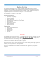
System Overview
The guillotine backgauge control system normally includes all the electrical and
mechanical parts needed for the installation and operation of the guillotine machine
backgauge. In some circumstances it may be necessary for the installer to modify the
supplied components or manufacture new parts to suit the machine.
The installation is divided in 2 main parts:
Mechanical Installation:
• Servomotor and pulleys
• Electrical cabinet
• Motion controller
• Sensors (Home, Clamp, Knife, False Plate)
• Start/Stop unit
• Wiring the air cushion
• Motor connection
• Mains connection
Programming:
• Motion Control Parameters
• Speed Setup
• Options Setup
• Stability Test
• Test Run
IMPORTANT!
All supplied cables are 4 meters long, it is possible that the cable will be longer than the
distance between components, if this happens DO NOT CUT THE CABLE, simply roll up
the cable until it is the desired length and clip together.
Cables can be ordered at different lengths if required.
Be sure the cables do not obstruct any movement and are safely placed tight against the
machine, this will prevent any future problems.
Do not coil the MOTOR wires or MAINS wires with encoder signal wires, keep them
separate.
Software Version 3.3b
5 of 44
Mechanical Installation
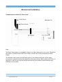
Component Location & Overview
Note:
The False Clamp sensor is intended to detect the false clamp when not in use. Therefore
the sensor is located where the False Clamp is stored. Not all machines have a False
Clamp.
The Encoder can be placed in different parts of the machine however when using a
servomotor it would normally be mounted on the servo motor. When using an AC motor it
may have to be driven from the leadscrew however the installer should minimise any
backlash in the system.
Software Version 3.3b
6 of 44
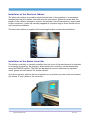
Installation of Servomotor and Pulleys
As we can see below the servo motor is located parallel to the lead screw and both
pulleys are aligned.
1. In order to provide a clear space to mount the new motor and pulleys, remove the
old motor and pulleys.
2. Decide where best to mount the motor bracket and remember that a pulley belt
is going to be installed so the distance needs to suit the belt. On some machines
it could be necessary for the installer to change the toothed belt or use an extra
bracket to ensure the alignment and centres are correct.
3. Mount the bracket to the machine so that the tension in the belt and alignment
between both pulleys can be adjusted.
4. Mount the Motor to the Bracket and ensure cables are clear of any moving parts.
5. Install and tension the Belt.
6. Rotate the leadscrew by hand at least 10 turns in both directions to check
alignment and belt runout.
7. Remove the belt to aid further commissioning.
Software Version 3.3b
7 of 44
Installation of the Electrical Cabinet
The electrical cabinet is normally located at the back of the machine in a convenient
location between the motion controller and the servomotor. Please be aware that the
length of the cables is enough to connect the encoder, Start/Stop switches, Sensors and
D-type connectors, these are normally supplied at 4 meters long so there should not be
any connection problems.
The electrical cabinet is supplied with mounting brackets to ease the installation.
Installation of the Motion Controller
The motion controller is normally installed into the front of the machine and is intended
to be easily accessed by the operator. Alternatively the controller can be mounted by
using the TRM POD system. The POD and Mechanical arm are ordered as an optional
extra, please see our website for further details.
Once the controller and the electrical cabinet are in position you can route and connect
the 44 and 37 way cables to the controller.
Software Version 3.3b
8 of 44
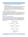
Installation of Sensors
The sensors provided are capable of detecting steel upto 4mm away however it is usually
good practice to install within 2-3mm of the object to ensure good accuracy. It should
also be positioned so that the face being detected has a 90 o edge to it rather than
rounded or sloping as these will give variable results and mismeasurement will occur.
1. Home Sensor
The home sensor is used to detect the travel limit of the backgauge. Every time
the Controller is turned ON and a program is executed the controller will search
for the home sensor, once detected and with the machine sizes correctly set, the
controller will know the exact position of the backgauge and proceed with the
program created by the user.
The Home Sensor should be plugged into the Home Sensor connector on the
electrical cabinet. The Home sensor itself must be placed under the table using
the sensor brackets, please note that depending on the distance between the
sensor and the knife the maximum cut will vary. The maximum cut is not from the
knife to the home sensor, it is from the knife to the front of the backgauge when
the sensor is detecting the backgauge.
IMPORTANT! - To avoid damage to the sensor and machine, NEVER INSTALL THE
SENSOR TOWARDS THE ONCOMING BACKGAUGE. The opject should be able to
pass under the sensor without damage.
When the sensor is powered up it can detect up to a distance of 4 mm on steel
and will light when detecting the backgauge. Move the backgauge forwards and
backwards to ensure the light turns on and off and to check clearance and sensing
distance.
2. Knife Sensor
The Knife Sensor should be plugged to the Knife Sensor connector on the
electrical cabinet.
The Knife Sensor is intended to sense the knife when it is in rest position, which is
when the knife is up. The idea is to place the sensor bracket in a fixed position on
the back side of the machine so that when the knife moves down and up the
sensor will detect the movement. Please be sure the sensor is close enough to the
knife so it will detect it and will light when detecting the knife.
3. Clamp Sensor
The Clamp Sensor should be plugged to the Clamp Sensor connector on the
electrical cabinet.
The Clamp Sensor is intended to sense the clamp when it is in rest position, which
Software Version 3.3b
9 of 44
it is when the clamp is up. The clamp sensor is normally located close to the
knife sensor and same recommendations for the installation apply.
4. False Clamp (shoe) Sensor
The sensor will be placed where the false clamp is stored when not in use. If the
sensor does not detect the False Clamp, the software assumes it IS in use and the
controller will use the minimum cut setting "Min Cut (clamp shoe)" as the
minimum cut. If the sensor does detect the False Clamp the controller will
assume it is NOT in use and will use the minimum cut setting "Min Cut (no shoe)".
The minimum cut settings are in the "Calibration Menu" explained in the second
part of this manual.
Installation of the START and STOP Buttons
The Start and Stop buttons can be mounted into the front of the machine for easy access
or into the POD if supplied. The Green Start button uses a N/O (normally open) contact
block with Red/Blue wires and the Black Stop button uses a N/C (normally closed)
contact block with Yellow/Green wires. These are normally supplied pre-wired and the
contact blocks just need to be clipped onto the rear of the buttons once they are
fastened in place.
Wiring up the air table connection
PROCUT has a parameter (column) in the Edit/Create screen called 'AIR' and the user
can select 2 options for this parameter 'YES' or 'NO'. If the parameter is set to 'YES' it
means that the 'Air Table enable' signal will be active when the backgauge is moving to
that position. This enable signal will be inactive when the backgauge has stopped and
the machine is ready to cut. If the AIR parameter is set to 'NO' the enable signal will
always be inactive.
Software Version 3.3b
10 of 44
In some cases is not necessary to wire up this connection as the machine already turns
the air ON or OFF without using the 'Air Table Enable' signal.
For wiring up the air table please look at the diagram " Air Connector Wiring" shown in
the next page.
Cut Enable and Hold Down enable
PROCUT has 2 outputs to enable a Cut and to enable the Hold Down (clamp). This is
optional and requires the user to install the connections as in the previous diagram.
Please note that this is not intended as a safety circuit, more to ensure the knife and
clamp are not active when the backgauge is moving. The safety circuits of the machine
should not be tampered with and should still be effective in preventing accidents as
originally intended.
Motor Connection
The pre-wired motor connector should be plugged into the motor connector on the
electrical cabinet and locked in place with the integral locking ring. This connector is
polarised to the connection can only be made one way. In the case of the AC Servo
system the inline plugs should be connected and the encoder connected to the cabinet.
Installing the Electronic Jog Wheel
The Jog wheel is an optional feature and it is intended to replace the hand wheel. When
installed, it allows the user to make fine accurate adjustments of the backgauge which
can then be stored in the program.
The Jog Wheel provided by TRM is to be plugged to the Jog Wheel connector on the
electrical cabinet.
Mains Connection
The system can be connected to 120 AC or to 230 AC mains at either 50 or 60Hz,
however internal modification has to be made to change the power supply. To avoid
damage the system will be shipped set to 230V unless otherwise requested. Please verify
what voltage is to be used before connecting it to the mains supply.
Mains connections are noisy signals and could affect the motion control signals, in order
to avoid this, ensure the mains cable is routed away from the control cables.
Please contact us for information on how to change voltages.
Please note that in all cases the earth pin must be connected.
Software Version 3.3b
11 of 44
Data Installation
Quick Start
Once the mechanical installation is finished you are ready to start the software setup.
The values setup here are different from machine to machine though some values are
the common.
Please remember that the data entered in the technical menu has to be as accurate as
possible in order to have an accurate cut and to avoid over-shooting axis limits.
Normally the controller will be shipped from the factory with default values set and fully
tested. If the backup battery has become flat over time (>6 months) then it may be
necessary to clear all data and programming to ensure the memory is clean and only
holds good data.
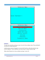
From the Welcome Menu shown above select 'Technical Menu' (F5 key) and enter the
master password.
Software Version 3.3b
12 of 44
Defaults
To clear the controller and setup as new, from the 'Service Menu' select 'Factory Defaults'
and enter the master password.
A yellow pop up menu will appear on screen with 2 options, select the machine type
from the options. If your machine is not shown select a similar machine type.
When asked 'Restore the factory defaults settings?', select OK
Software Version 3.3b
13 of 44
When asked 'Delete database also?' select OK.
Service Record
From 'Service Menu' Select 'Service Record' and set the 'Machine Service Interval Cuts'
(number of cuts made before service) and the 'Actuator Service Interval' ( number of
leadscrew meters moved before service) when one of these limits is reached the
controller will request a Service Password before entering the Edit/Create menu.
Software Version 3.3b
14 of 44
Return to the 'Technical Menu' by pressing the MENU key.
Test IO
From the Technical Menu select 'Diagnostic Menu' and then select 'Test I/O' you will see
the screen shown below:
In this menu you can verify if the sensors and its connections are working properly. On
the screen above you can see some of the digital inputs are activated.
If you want to test the Home Sensor, place a metallic object in front of the sensor and
Software Version 3.3b
15 of 44
verify that the input is switching from '0' to '1' on the screen. Do the same test with the
other sensors. If one of the sensors is not working, check that the light on the rear of
the sensor turns on and off, this indicates power is present at the sensor. Trace the
wiring and ensure all connections are good if any input does not work.
It will not be possible to check the emergency stop input in this menu as the servo motor
is not running at this stage!
In the same Test I/O Menu you can test the digital outputs shown in the lower bar. In
hexadecimal Output 0 is on the right moving to F on the left:
FEDCBA9876543210
If you have connected the Clamp Enable, Cut Enable and Air Enable relays you can turn
ON or OFF the relays manually from this screen. By using the Left and Right arrow keys
in order to move the cursor along the different outputs and pressing '1' for turning a
particular output ON or '0' for turning it OFF.
The outputs used are:
• 9 = Air enable
• A = Cut Enable
• B = Clamp Enable
Turn them ON and OFF and verify the relays are working, if not trace cable routing and
connections and verify that all are correct.
Calibration
From the 'Technical Menu' select 'Calibration'.
Complete all the values in the calibration menu to suit your size of machine, for now
leave the 'Maximum Cut' , 'Zero offset', 'Play in mm' unless you know the values to enter.
For more information refer to the complete Data Installation section in this manual.
Software Version 3.3b
16 of 44
Motion Control
1. From the 'Technical Menu' select 'Motion Control' please verify all the values are
the same as shown below:
2. You are now ready to test the encoder connection. If the encoder is connected to
the motor directly move the motor shaft exactly one turn (360o) and verify if E0
equals the expected number of pulses. i.e. if using a 1000ppr quadrature encoder
the value will be 4000. AC Servo drives are usually preset to 3000ppr. If the Value
is +/-4000 or near then move the lead screw one turn back to its original position.
Now verify E0 = 00000. If you were unable to obtain both numbers then verify the
encoder connections and try again. If you obtained both numbers or very close to
those numbers (4000 and 00000) then your encoder is working well and you can
continue with the next step.
Remember if you turn the leadscrew and the encoder is mounted on the motor
you will need to take account of the gear ratio used in one revolution.
3. You are now ready to test the motor with no load, please verify that the motor is
free to revolve and the toothed belt is not fitted. Also verify all connectors are
plugged firmly in the electrical cabinet and the controller, including the aux
connector as this carries an ESTOP signal which if broken will prevent the system
starting up.
4. Press the Start button on the controller (traffic light F7 key) and press the green
START button when prompted. If there are no problems the motor should be stood
still holding position. If the motor is unstable or not holding position refer to the
troubleshooting manual. Press Stop and then MENU to return to the technical
menu.
5. If the motor was holding position increase the 'Axis Gain 0' in units of 50 up to the
maximum value in which the motor is stable. Each time you make a change in a
'Motion Control' Menu parameter press the ENTER key so the controller
acknowledges the new value and proceed to test if the motor is still stable by
turning the motor. If the motor becomes unstable at some point when increasing
this value, use the previous value at which the motor was still stable. Once you
have obtained the maximum value at which the axis was stable continue to next
step.
6. Now that the motor is stable, select 'Options' from the 'Technical Menu' and Setup
all the data required or leave the default values as shown on the drawing below.
There is one particularly important parameter here and it is 'Blade Sensor'. Blade
Sensor has 2 states and its selection depends on where you have placed the knife
sensor. Select 'Low' if the sensor detects the blade (knife) when it is in rest
position, or 'High' if the sensor detects the blade when executing the cut. By
pressing the ENTER key the user can change the state of parameters from High to
Low or ON to OFF. For more information refer to the complete Data Installation
Software Version 3.3b
17 of 44
section.
7. Press the MENU key to return to the 'technical menu' and select 'Calibration' in
order to set up the maximum cut.
8. Press the F7 key under the icon shown on the bottom of the screen, and press
START when prompted. IMPORTANT: If you need to set the "Maximum cut" again
you need to turn OFF-ON the controller before doing it so the Home position will
clear.
9. Now the motor should start moving slowly, please verify the motor is moving in
the correct direction, the backgauge should be moving backwards in the case that
the toothed belt was fitted. If it is moving in the correct direction, go to step 12.
10.If the motor is moving in the wrong direction, press STOP and MENU to return to
the 'Technical Menu'. Select 'Motion Control'. Now edit the setting 'Invert Direction'
to '1' and return to step 8.
11.If the motor is moving in the right direction, turn the power OFF by pressing STOP,
disconnect the power to the cabinet and proceed to fit the toothed belt,
tensioning it correctly.
12.With the toothed belt fitted, go to calibration again and press the F7 key under
the icon and the START button when prompted, now the motor and backgauge
should start moving backwards and looking for the home sensor.
13.When the sensor detects the backgauge the motor will stop and hold position, this
is the HOME position of the backgauge. A message on screen will be displayed
asking for the Maximum Cut. The maximum cut is the distance from the front of
the backgauge to the knife. Using a tape measure, measure the distance from the
knife to the front of the backgauge enter the value and press ENTER. The
'Maximum Cut' should be set now.
14.You are now ready to use the system in the Edit/Create Menu. Please refer to the
User's Manual to create a short program for testing the accuracy and movement of
the backgauge. When making the test program is good practice to enter whole
numbers, for example 900.00, 700.00, 500.00. Below is a screen showing the
Motor Power Graph, Actual Position and Programmed Position.
Software Version 3.3b
18 of 44
15.Once you have created the test program, you are ready to run the program by
pressing F7, the backgauge will start moving towards the program's first position.
Select one of the following options:
1. When the backgauge is moving from one position to the other, the motor
Power Graph (shown above in the screen shot) becomes Red part of the time
or all the time during movement.
Action: Stop the program by pressing F8 Key. Go to 'Speed Settings' in the
'Technical Menu' and decrease the 'Max speed' in units of 5 and repeat the test
until the graph is never in red.
2. When the backgauge is moving from one position to the other the Power Graph
is in Green.
Action: If the power graph is never in red, you can set the controller's
maximum speed and/or acceleration at a higher value. Once you have
selected the highest possible value for 'Maximum Speed' and 'Max Acc Lim' and
the Power Graph is never in red, continue with next step.
16.On the Edit/Create Menu Execute the test program and check if the control of the
backgauge is working well and that the Motor Power Graph is never in red.
Proceed to verify the accuracy of the positioning. Select one of the following
options:
1. When the backgauge moves to a position and stops, the error between the
programmed position and the actual position (see the above graph) shown on
the controller has an error. For example:
Programmed Position
('Length' column on
controller)
900.00
Actual posi tion
Error (+/-)
(Displayed on big numbers on controller) (Actual position - Programmed position)
900.85
0.85
Action: Stop the program and go to Motion Control in the Technical Menu. In
Motion Control Menu press F7 and increase 'Axis Gain 0' in units of 5 up to a
Software Version 3.3b
19 of 44
value in which the motor is still stable (firm in position without vibration).
Each time you make a change in a 'Motion Control' Menu parameter press the
ENTER key so the controller acknowledges the new value and proceed to test
if the motor is still stable by moving the backgauge by hand. If the motor
becomes unstable at some point when increasing this value, use the previous
value at which the motor was still stable.
Once you have obtained the maximum value at which the motor is stable
proceed to do the same with the 'Int Limit' (Integral Limit) but in this case
increasing the value in units of 50 up to a value in which the motor is still
stable. Each time you make a change in a 'Motion Control' Menu parameter test
if the motor is still stable by moving the backgauge with the front wheel. If
the motor becomes unstable at some point when increasing this value, use the
previous value at which the motor was still stable and repeat this step (step
29).
2. When the backgauge moves to a position programmed on the controller, there
is no error between the actual position and the programmed position, however
there is an error between actual position and the real position (measured with
tape measure).
Action: Go to Calibration Menu and set the values as accurately as possible.
The more accurate the values you enter here the more accurate the machine
will be. Maximum cut is very important as if this value is wrong all position
control will be wrong! An explanation of each parameter follows below:
Ball Screw Lead mm.
This setting varies depending on the machine and indicates how much
the backgauge moves in one revolution of the leadscrew or ballscrew.
In order to find this value, move the backgauge to the middle of the
table. Then move it forward (towards the knife) manually for at least
20mm. This will be the starting position of the measurement you are
about to do. Mark the starting position with a line.
Turn ON the controller and go to the "Motion Control" menu (in the
technical menu). On the lower part of the screen, you should see
E0=0000. Now proceed to move the backgauge forward 20 revolutions
of the lead screw until: E0=[80000 x (gear ratio)]. Now proceed to
mark this position in the paper with a line.
Measure the distance between the first mark and the second mark,
and divide that value by 20, the result will be your Ball Screw lead.
Please note that if the lead screw is metric the result should be a
whole number, for example 25.00mm, 10.00mm, 9.00mm, 6.00mm
etc. If it is Imperial enter the metric converted value. i.e. 1” = 25.4
Software Version 3.3b
20 of 44
Encoder PPR
Indicates the number of encoder pulses in 1 revolution, normally 1000
if using the DC motor encoder supplied by TRM or 3000 on AC Servos.
Gear Ratio
This is the gear ratio between the motor and the lead screw, if the
encoder is mounted directly in the lead screw the gear ratio is 1
otherwise standard ratio supplied is 4.8:1.
Maximum Cut
The Maximum cut represents the maximum distance in millimetres
between the knife and the front of the backgauge when the home
sensor is detecting the backgauge. The value set here is used by the
controller to ensure that the operator sets movements within the
system boundaries. The controller will not allow the operator to enter
position data greater than the Maximum length.
In order to measure the maximum distance between the knife and the
front of the backgauge, (once all the settings in the technical menu
has been set up) press the F7 key below the only icon shown on the
Calibration menu. The backgauge should start moving backwards in
search for the home sensor and will stop just when the home sensor
detects the backgauge, this allows the installer to measure the
maximum distance between the knife and the front of the backgauge.
IMPORTANT: If you are doing this for second time you need to turn
OFF-ON the controller before doing it so the home position will clear.
Min Cut (clamp shoe)
This setting, in millimetres, represents the smallest cut with the false
clamp (shoe) fitted. The value set here is used by the controller to
ensure that the operator sets movements within the travel limits. The
controller will not allow the operator to enter a position lower than
the minimum cut length.
After entering all the values in Calibration Menu repeat this step (step 16).
3. When the backgauge goes to a position programmed on the controller and
there is no error between the actual position and the programmed position the
system is set accurately.
Congratulations you have successfully installed PROCUT! Go to the Edit/Create Menu and
start using PROCUT.
For further explanation of the technical menu and installation settings please refer to
the complete Installation Manual.
Software Version 3.3b
21 of 44
Technical Setup
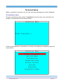
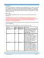
When a controller is turned on for the first time the opening menu will be displayed.
The Installation Menu
To begin installation select option 5 installation from the menu, the controller will
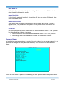
change to the password screen shown below:
If the correct password is entered the controller will display the installation menu as
shown below:
Software Version 3.3b
22 of 44
The menu is laid out in the order in which the information is needed, this makes it
easier to enter the information the system needs.
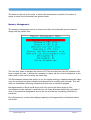
Memory Management
The memory management screen is where user files can be backed up and restored
along with the system files.
The first four items to backup and restore CUT files are the files that the operators will
have created for jobs. It allows the company to keep a job for recall at sometime in the
future and to then cut in exactly the same way.
The Environment backup and restore is for the system settings. A backup should be taken
once the machine has been installed and deemed to be working and accurate. This will
allow re-installation following unintentional data loss or software upgrade.
Defragmentation of the A and B drives will only need to be done rarely as files
accumulate and are deleted. A and B drives are those allocated within the controller. C
drive is the pendrive designation and we do not provide any formatting facilities for
pendrives.
Drive Properties is a menu that displays capacity and fragmentation information about
the drives.
Software Version 3.3b
23 of 44
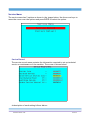
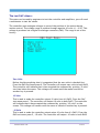
Service Menu
The service menu has 2 options as shown in the images below. Use the arrow keys to
move the cursor over the options and press ENTER to select the option.
Service Record
The service record menu contains the information required to set up technical
service or maintenance of the machine. The screen is shown below:
A description of each setting follows below:
Software Version 3.3b
24 of 44
Total No. Cuts
This setting cannot be changed by the user. Total No. Cuts indicates the total
number of cuts executed in the machine since the software was installed. A Reset to
defaults will not clear the counter, if it becomes necessary to clear this, please
contact the factory for the correct code.
Cuts Since Service
This setting cannot be changed by the user. 'Cuts Since Service' indicates the number
of cuts executed in the machine since last time serviced.
Machine Service Interval Cuts
This setting can be set up and indicates the number of cuts to be made before the
machine requires a general service.
Total Distance Moved
This setting cannot be changed by the user. Total distance moved indicates the total
distance in meters that the backgauge has travelled since installed.
Moved Since Service
This setting cannot be changed by the user. Moved Since Service indicates the
distance in meters that the backgauge has moved since last time serviced.
Actuator Service Interval
This setting can be set up and indicates the distance in meters that the backgauge
has to move before the operator is prompted for service.
Software Version 3.3b
25 of 44
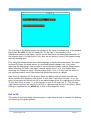
Factory Defaults
The second option on the Service Menu is Factory defaults as shown below, it is
designed to load all the default data into the controller.
It is good practice for the technical person installing the system to run the factory
defaults routine before entering the data for that particular machine.
1. Select 'Factory Defaults' and enter the master password.
2. A pop up menu will appear on screen, select the machine type from the
options. If your machine is not shown select a similar machine type and then
goto the Calibration menu to correct any dimensions needed.
Software Version 3.3b
26 of 44
You will also be prompted “Delete database also?” if confirmed this will clear any stored
files on older systems and does not apply to the new SMC controllers with A, B and C
drive allocations. (older controllers had no USB and no drive allocations)
Calibration Menu
From the technical menu select 'Calibration', the controller will display the Calibration
Menu as shown below:
Inside the Calibration menu is stored all the data the controller needs to make accurate
movements between the machine limits.
A description of each setting follows below:
Ball Screw Lead mm.
This setting varies depending on the machine and indicates how much the backgauge
moves in one revolution of the Leadscrew or ballscrew.
Gear Ratio
TRM supplies various types of gear ratio, 4.8:1, or 3:1 etc., verify what gear ratio
you have ordered and enter the value here. To calculate this it is the number of
teeth on the large pulley divided by the number of teeth on the small pulley.
Maximum Cut
The Maximum cut represents the maximum distance in millimetres between the
knife and the front of the backgauge when the home sensor is detecting the
backgauge. The value set here is used by the controller to ensure that the operator
Software Version 3.3b
27 of 44
sets movements within the system boundaries. Please note that if the value is set to
zero the system will not test the data entered by the operator. The controller will
not allow the operator to enter position data greater than the Maximum length.
In order to measure the maximum distance between the knife and the front of the
backgauge, (once all the settings in the technical menu has been set up) press the F
key below the only icon shown on the Calibration menu. The back gauge should start
moving backwards in search for the home sensor and will stop just when the home
sensor detects the backgauge, this allows to measure the maximum distance
between the knife and the front of the backgauge.
Min Cut (clamp shoe)
This setting, in millimetres, represents the smallest possible cut when the false
clamp is in position. The value set here is used by the controller to ensure that the
operator sets movements within the travel limits. The controller will not allow the
operator to enter a position lower than the minimum cut length.
Min Cut (no shoe)
This setting, in millimetres, represents the smallest cut without the false clamp
(shoe) in. The value set here is used by the controller to ensure that the operator
sets movements within the travel limits. The controller will not allow the operator
to enter a position lower than the minimum cut length.
Zero Offset mm.
This setting, in millimetres, is designed to ease the installation of the Home Sensor.
For example if the system is installed in a 92 cm machine and maximum cut is
therefore 920 mm, the sensor can actually be placed a little bit further back, lets
say 5 mm. If the Zero Offset setting is set to 0 mm the maximum cut would be
925.00 mm but if the Zero Offset setting is set to 5 mm the maximum cut will be
920.00 mm.
Play in mm.
This setting is designed to minimise the error due to the leadscrew wear and is only
functional when the backgauge is moving backwards. The system moves back beyond
the set position by the programmed distance and then moves forward to the actual
position. This ensures that all positions are moved to in the forwards direction and
are therefore consistent.
Push Position
This setting, in millimetres, is used mainly by the 'Label optimise' menu when the
program is created automatically or in manual mode. The subtraction between the
"length" value and "Knock position" is the one the system will enter into the 'Push'
column in the Edit/Create menu.
Software Version 3.3b
28 of 44
Load Position
This setting, in millimetres, is used in automatic mode when turning ON the setting
"Load Position" located in options.
Encoder PPR
Indicates the number of encoder pulses in 1 revolution, normally 1000 if using the
encoder supplied for a DC System or 3000 for an AC Servo system.
Machine Width
This setting is in millimetres and is designed for the system to be able to make the
calculations when using the 'label optimisation mode'.
Once Calibration menu is set up press the MENU key twice to go back to the Installation
menu
Software Version 3.3b
29 of 44
Speed Settings
From the installation menu, using the arrow keys move the cursor to the Speed Settings
option and press ENTER. Note the user must ensure that the maximum speeds are
properly set up. It is vital that the maximum speeds of each axis are correctly set, if
the maximum motor speed is set higher than the motor can attain, the system will lose
control of the motor. The motor speeds are set normally in quadrature pulses per sample
period (QPSP). This makes setting the system up simple as it is very easy to calculate the
maxim motor speeds and enter the value. When setting the motor speed one must
ensure that the limits of the system are respected, always set motors to run at a safe
speed. Please see the speed set up menu below:
Max Acceleration / Deceleration Limit
Both the acceleration and deceleration of both axis is controlled in the same
manner. It is set in units of travel per period. This can be either quadrature pulses
per sample period or units of travel per second. The normal system is set in QPSP
unless stated on the menu. The formula for acceleration is given by:
Vi = (Ap / 255) x 1250.
Where Vi = velocity increase per second squared, and Ap is the acceleration
parameter entered by the user.
In reality it is almost impossible for users to calculate the optimum maximum
acceleration which often has to be set by measuring the motor current during
acceleration and deceleration and ensuring that these are within design limits.
Where the system is set up in units per minute or second the acceleration and
deceleration is set to reach a velocity increase per second of the acceleration
Software Version 3.3b
30 of 44
parameter. For example an axis which has been calibrated in millimetres will
accelerate at the rate of acceleration units per millimetre squared. In this case an
axis will accelerate at the programmed number of units per millimetre second
squared. If the figure 10 is entered for acceleration then the axis will accelerate at
the rate of 10 millimetres per second squared.
A common mistake made by people setting up systems, is that the acceleration is set
too high. If the acceleration is set too high then the motor will fail to reach the
destination set by the controller and a huge following error will occur. Although the
motor may recover its position in due course the motion profile will be wrong and
ultimately the motor may burn out. This will be obvious in the run screen as the
power graph will be showing red. Decrease the acceleration until the graph shows
green.
Once the motion control speeds have been set the user may exit the menu by
pressing the menu key.
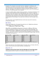
Max Velocity
Unless stated otherwise on the menu the speeds are set in Quadrature pulses per
sample period. This is given by the formula
• V=((RPM motor x PPR encoder) / 20520)
Where RPM is the MAXIMUM working speed of the motor in RPM and PPR is the
number of pulses per revolution of the encoder. Please see the table below. This
shows speed settings for various motor speed ranges when fitted with 1000 pulse
encoder. If the version of PROCUT you have has been configured in units per period
(normally mm/min or mm/sec) values must be calculated by using the gear ratio and
the speed of the motors etc.
Maximum RPM
Speed value
Maximum RPM
Speed Value
500
24
1,000
48
1,500
73
2,000
97
2,500
121
3,000
146
3,500
170
4,000
194
4,500
219
5,000
243
5,500
268
6,000
292
This table shows Maximum speeds for motors fitted with 1000 P.P.R. Encoder in
QPSP
Please note that this is the maximum speed the motor can run, however when the
motor is with load the motor speed could be considerably less.
Return Vel. in %
The Return Velocity is the value at which the backgauge will move when moving
backwards in the automatic mode. Note that this value is a % of the 'Max Speed'
setting explained above therefore the maximum number allowed is 100%.
Software Version 3.3b
31 of 44
Forward Vel. in %
The Forward Velocity is the value at which the backgauge will move when moving in
the forward direction in the automatic mode. Please note that this value is a % of
the 'Max Speed' setting explained above therefore the maximum number allowed is
100%. Generally it is a good idea to keep the forward speed lower than the return
speed as the paper will have less tendency to slide on each other when stopping and
reduce the time taken to “block” the paper back up again.
Max Home Velocity
This, unless stated otherwise on the menu, is set in percentage of maximum speed.
See section above (Maximum Speed) for more information. The maximum home
speed velocity is the velocity that the system returns to home at. This should
normally be quite low. Remember that the zero point may be near the end of the
axis travel and therefore if the velocity is high there is a chance of the axis hitting
the end of travel.
Default Jog Spd.
The value entered for 'Default Jog Speed' governs the speed at which the backgauge
will move when using the 'Fast forward' or 'Fast reverse' controls in the Manual
mode.
Important! Enter a very low value to avoid crashes against the machine limits!
Software Version 3.3b
32 of 44
Motion Control
From the Technical menu select the option 'Motion Control'. Having calibrated and set
the motion travel speeds etc. the user needs to set the motion parameters, these are in
the form of gain and filter settings for the axis.
Note that there is Axis 0 and Axis 1, this is because on some bigger machines there could
be 2 servomotors, if you are using just 1 servomotor then the data to be set is just for
Axis 0.
Gain Axis 'x'
The gain setting is a figure that the controller uses to set the stiffness or tolerance
of the axis positioning. The lower the gain is set the easier it is to get the system to
become stable, therefore never set the gain higher than you need. When you set the
gain you will be able to see how that affects the positioning of the axis by the
encoder positions shown at the bottom of the screen. You will see that there are two
sets of figures at the bottom of the screen these are DAC and Encoder Where DAC
represents the current DAC output and Encoder represents the current encoder
position, the controller will attempt to position all axis at zero. Note that the value
for Gain is 0 and Encoder is 0 at this point as power has not been enabled.
Filter A 'x'
Filter A parameter represents the primary digital filter where the higher the value
the lower the filtering frequency, for example a high speed motor normally requires
a filter 'A' setting of approximately 210, a slower DC motor would require a setting
of approximately 250, Note: this parameter has a maximum setting of 255.
Software Version 3.3b
33 of 44
Filter B 'x'
The 'Filter B' parameter represents the secondary digital filter, it tends to deal with
high frequency isolation in the motor. Like the 'Filter A' parameter it is suggested
that this is set with the gain relatively low and that the 'Filter A' parameter is set
roughly to the correct value then the 'Filter B' parameter can be adjusted. Typical
values are around 64.
Igain / Ilim
These settings are designed to correct the positioning error when the motor is
stationary.
IMPORTANT - Once the system is stable and has been thoroughly tested, it is
recommended that the end user write the values down and store them in a safe
place in-case they need to be reloaded in the future or use the “Backup
Environment” in the memory menu.
The Integral value is shown at the bottom of the screen and becomes live when the
motor is energised.
Below you will find an explanation of the motion control settings.
Setting
Gain Axis 0
Default Value range
Value
From - To
800
0 to 9999
Filter A 0
210
0 to 255
Filter B 0
64
0 to 255
Software Version 3.3b
Explanation
Position Loop Gain. Determines
how much position error will
be allowed. The bigger the
value the lower the position
error allowed.
This filter corrects the speed of
primary damping of the
system. The bigger the value
the lower the filter frequency.
In this way, motors with poor
acceleration characteristics
will require higher values. For
low inertia motor the value
tends to be lower.
This filter corrects the speed of
secondary damping of the
system. The bigger the value
the lower the filter frequency.
As the secondary damping is of
higher frequency compared to
the primary damping this filter
is normally lower than Filter A,
however in some low inertia
34 of 44
Igain
0256
0 to 999
Integral Limit
1024
0 to 4000
Phase
0
0 or 1
motors (AC servo motors) filter
B could be higher than filter A.
Integral Gain. This is the static
position error. This parameter
determines how quick the
Integral gain grows from '0'.
The bigger the value the faster
the integral gain will grow.
Integral Limit is the maximum
value at which the Integral
Gain can grow.
If the motor is unstable the
phase can be changed her and
re-tested to check stability.
Following Error
Following Error. This is the maximum permissible difference between the
commanded position of an axis and its actual position. If no following error is set
(0000) the controller will not look for any following error. When a following error is
set, the bigger the value the bigger the following error tolerated. If the following
error is bigger than the value set the controller will trip out and a message on screen
will be shown. Maximum value is 9999.
No of active axis
This value is normally set to 1 for a single motor system. On larger machines where 2
motors are used this would be set to 2.
Invert Direction
Depending on how the motor is mounted a situation could arise where the stop is
moving in the wrong direction, however it is under control and stable. Setting this
from 0 to a 1 will reverse the direction of the motor.
Motor Activation Delay
On AC systems and some DC systems this value is set to allow a short delay for the
drive to power up before motion is enabled. In some cases if the drive is enabled
and the voltage is low the position desired will not be achieved and a larger
command output given. Once the voltage has stabilised the motor could then jump
causing erratic control during start up. This is set in milliseconds (ms) and a
maximum of 2000 can be set.
Software Version 3.3b
35 of 44
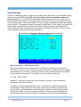
Options Menu
From the Installation Menu select 'Options' and the following screen will appear:
An explanation of each setting follows below:
Decimal Places (Inch)
This setting indicates the number of decimal places (when in inches) that the system
will show on the Edit/Create screen when moving to position. When displaying the
position in Inches the maximum number of decimal places is 3.
Decimal Places (mm)
This setting indicates the number of decimal places (when in millimetres) that the
system will show on the Edit/Create screen when moving to position. When
displaying the position in millimetres the maximum number of decimal places is 3.
Measurement Standard
Here the user can select in what unit to display the position, Inches or Millimetres.
However when running a program in Edit/Create the user can still temporarily
change between either standard from the local options menu.
Use Load Position
If selected 'On' the backgauge's first action when running a program will be to move
to the 'Knock Position' set up in calibration, a message on the screen will prompt the
user to load the paper into position and to press ENTER to continue with the job.
Software Version 3.3b
36 of 44
Label Mode Air
If the Air relay option is installed, this setting will turn On or turn Off the air when
using the label optimisation mode.
Manual Mode Air
If the Air relay option is installed, this setting will turn On or turn Off the air when
using the manual mode.
Manual Mode Pushout
When set to “On” a Pushout operation will be performed after a cut is made in
manual mode. The amount that the paper will be pushed out is specified in the
“Calibration Menu”
Cut Sensor
On some machines the blade sensor does not detect the blade when in 'rest' position
but when the blade is down, therefore:
• Select 'Low' when the Sensor detects the blade when it is in 'rest' position.
• Select 'High' when the Blade sensor detects the blade when cutting.
Password Menu
In installations where permission is required to enter data or to use certain menus it is a
good idea to change the user passwords regularly. This is achieved via the Password
menu.
There are two levels of password these being the user passwords and the system master
Software Version 3.3b
37 of 44
password. When first supplied, your distributor will advise you on the initial password
settings. To make changes to the user passwords enter the password menu from the
Technical Menu as shown in the figure above. The enter password screen will appear, at
the prompt enter either the master or the password menu user password.
Entering a New Password
Move the cursor to the line that requires editing. Overtype the existing password
with up to 6 characters. Legal characters include alphanumeric and symbols. We
would suggest that the passwords are written down and stored in a safe place for
future reference should any be forgotten.
The Diagnostic Menu
From the technical menu shown above select 'Diagnostic Menu'. The menu allows basic
controller testing and setting of the real time clock. Please see the diagnostic menu
below:
Set Time
From the diagnostic menu select item “Set Time”. The set time menu will be drawn
as shown below:
Software Version 3.3b
38 of 44
The clock is set in only the 24 hour format. For example to set the time to 5:45:00
in the evening, enter 17 for the hour, the controller will move to the next value
field. Then enter the minutes, in this case 45, the controller will move to the next
value field so the display will read 17:45: Now enter the zeros. The clock will start
exactly when we finish typing the last digit in so enter the first 0 and wait for the
reference clock to read 17:45:00 and enter the final 0.
The time will be set and the controller will return the display to the diagnostic
menu. Please note that the clock is not self adjusting for winter/summer times and
must be adjusted as required.
Setting the Date
Setting the data is similar to setting the time shown above. From the diagnostic
menu select item “Set Date”.
Software Version 3.3b
39 of 44
The set date is exactly the same as the set time menu shown except that the display
reads “Set date menu and the prompt reads DD-MM-YY where DD represents the day
of the month, MM the month and YY the last two digits of the year. At the prompt
enter the date in the two digit format e.g. to enter the 1st of June 2002 enter 0106-02. Note that the controller adds the hyphen ‘-’ automatically.
Software Version 3.3b
40 of 44
The test DAC's Menu:
This menu can be used by engineers to test the controller and amplifiers, you will need
a multimeter to test the values.
The controller uses analogue voltages to control the position of the motors during
motion control. The voltage range is positive through negative 10 volts (+/- 10 V). This
voltage is produced via a digital to analogue converter (DAC). The range is set at the
factory
Zero Volts
Before checking anything else it is suggested that the zero volts is checked first.
From the DAC test menu press 0. The controller will output zero volts to both DACS
The controller will indicate that it has accepted the command by printing “O volts”
two lines below the menu. This voltage will remain until the menu is exited or
another key is pressed.
10 Volts
This is used to make the controller output 10 volts from it’s DACS. From the DAC
test menu press 1. The controller will output 10 volts to both DACS. The controller
will indicate that it has accepted the command by printing “1O volts” on the
screen. This voltage will remain until the menu is exited or another key is pressed.
-10 Volts
This is used to make the controller output minus 10 volts from it’s DACS. From the
DAC test menu press 2, -10 volts. The controller will output -10 volts to both DACS
Software Version 3.3b
41 of 44
The controller will indicate that it has accepted the command by printing “-1O
volts” on the screen. This voltage will remain until the menu is exited or another
key is pressed.
Ramp Drivers
This function causes a saw tooth pattern to output to the drivers (digital outputs).
Using suitable loads and an oscilloscope it is possible to check the drivers
dynamically. The highest frequency is output to driver 0 and the lowest to driver 7.
To use this function from the DAC test menu, press 3 Ramp drivers. The controller
will output the sawtooth to the drivers and it will indicate that it has accepted the
command by printing “Ramping Drv” on the screen. This voltage will remain until
the menu is exited or another key is pressed.
Ramp DACS
This function causes a saw tooth pattern to output to the DACS. Using suitable loads
and an oscilloscope it is possible to check the DACS dynamically. The iDACS produce
a high quality linear sawtooth waveform. Any errors in the linear section of this
waveform might indicate that the DACS have been damaged. To use this function
from the DAC test menu press 4 Ramp DACS. The controller will output the sawtooth
to the DACS and it will indicate that it has accepted the command by printing
“Ramping DAC” on the screen. These voltages will remain until the menu is exited
or another key is pressed.
Test I/O Menu
The test I/O menu is very useful as it allows the machine to be tested by controlling the
drivers and monitoring the Home Sensor, Knife Sensor and Clamp Sensor. The menu
displays both the state of the inputs and the outputs. The outputs can be individually set
on or off.
Software Version 3.3b
42 of 44
The first line of the display shows the number of the input in hexadecimal with the Most
Significant Bit (MSB) on the left hand side. To the right of the heading is the
hexadecimal value of the inputs. On the second line there is a binary representation of
the outputs where 1 is high and 0 is low. Now we are going to verify if the sensors being
used are working well.
First using the manual wheel move the backgauge to wards the home sensor. The value
for input 0 (where the home sensor is connected) should change from 1 to 0 when
detecting the backgauge. Now proceed to verify the Knife sensor and the Clamp sensor.
When detecting the knife, the input 2 should change from 1 to 0, and finally when
detecting the clamp the input 3 should change from 1 to 0. If in any case the sensor is
not working properly verify the connection inside the electrical cabinet.
Next there is a heading for the drivers, these are MSB on the left hand side with the
driver number directly above each driver. In this case 0 represents off and 1 is on. On
entry to the menu all drivers are off.In the above image driver 0 is highlighted in white.
To turn this driver on press ‘1’ on the keypad to turn it off again use ‘0’. The left and
right hand arrow keys are used to scroll left or right allowing access to all drivers. When
testing is complete use the MENU key to exit to the diagnostic menu.
Exit to OS:
This option is used only under the instruction of your supplier and is normally for backing
up/restoring or program updates.
Software Version 3.3b
43 of 44
Software Version 3.3b
44 of 44