1
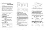
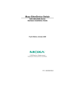
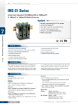
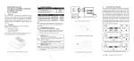
• Side Panel View
AUTO
100
FDX
LFP
FDX
1
2
3
4
5
FORCE
10
HDX
LFP DIS
HDX-FX
Media Converter User’s Guide
S1
Second Edition, June 2008
1. Overview
TP
MOXA Media Converter is a standalone physical layer device that
converts between 10/100BaseT(X) and 100BaseFX segments of the
same network. The converter supports Link Fault Pass-through for
easily tracing network link failures, and the LFP function enhances the
integrity and conformity of TP-Fiber linking to make the network
easier to maintain. ME51 is powered by an external power adaptor or
USB port on the hosting device (e.g., PC or NB). The option of using
USB port power, which is unique to ME51 for products of this type,
offers greater flexibility when deploying ME51 in the field.
• Rear Panel View
USB A Type Jack
USB Cable
100FX Fiber
Network
2. Package Checklist
MOXA ME51 products are shipped with the following items:
• 1 ME51-M-SC, 1 ME51-M-ST or 1 ME-S-SC
• AC-DC Power Adapter
• ME51 User's Manual
Please notify your sales representative immediately if any of the above
items is missing or damaged
4. Wiring the Power Inputs
Ä Note: The Media Converter is hot-swappable.
Wear a grounding device for electrostatic discharge
USB B Type Jack
Fiber Optic
RJ-45 Jack
10/100 Ethernet
Switch/NIC
Cat. 5 Cable
ME51 with AC-DC Power Adapter
1. Enabled power source from AC-DC Power Adapter by dip switch
setting(Refer to Chapter 6 dip switch setting)
ME51 with USB power source(Type B-to-Type A Plug) and
FX/TP connection
3. Model Description
2. Verify that the AC-DC adapter conforms to your country
AC power requirement and then insert the power plug
5. Communication Connection
ME51-M-SC: 10/100BaseT(X) to 100BaseFX media converter;
multi mode, SC type fiber connection
3. Connect ME51 for network connection.
ME51-M-ST: 10/100BaseT(X) to 100BaseFX media converter;
multi mode, ST type fiber connection
ME51-S-SC: 10/100BaseT(X) to 100BaseFX media converter;
single mode, SC type fiber connection
Panel Layout of ME51 series
• Front Panel View
ME51 models have one 10/100BaseT(X) Ethernet port, and one 100
BaseFX (SC or ST type connector) fiber port.
ME51 with Self Powering Cable (USB)
Enable power source from USB by dip switch setting (Refer to Chapter
6 dip switch setting)
Ä Note: Please ensure that the dip switch is on the right side of
slide switch
Install USB cable. Plug type A connector in PC(NB)'s USB
and type B connector in the ME51’s USB port (See Fig. 1)
5.1 10/100BaseT(X) Ethernet Port Connection
ME51 supports auto MDI/MDI-X. Below we show pinouts for both MDI
(NIC-type) ports and MDI-X (HUB/Switch-type) ports, and also show
cable wiring diagrams for straight-through and cross-over Ethernet cables.
port(jack)
RJ45 (8-pin) to RJ45 (8-pin) Straight-Through Cable Wiring
Install the media cable for network connection
TX
RX
FX
TP
LNK
/ACT
Warning:
Please make sure that the power of PC/NB is
turned on, or else the ME51 will not work.
100
Bridge Media Converter
10/100Base-TX to 100Base-FX
FDX
/COL
—1—
PWR
—2—
—3—
RJ45 (8-pin) to RJ45 (8-pin) Cross-Over Cable Wiring
7. Link Fault Pass Through
ÄNote: Link fault pass through (LFP) function will be enabled by dip
6. Dip Switch Settings
Power inputs settings
Enabled power source
from USB
Enabled power source
from AC-DC Power
Adapter
5VDC
switch setting. Disable LFP function by setting dip switch to LLFP
DIS.
This media converter supports link fault pass through (LFP) in
TX/FX converter application. Link status on one port is
propagated to the other port to notify the remote nodes. If TP port
is unplugged, this converter stops transmission on fiber port. This
causes the remote fiber node link to fail. LED shows the link failure
on both TP and fiber ports. If fiber link fails, this converter restarts
auto-negotiation on TP port but always stays in the link failure
state. This causes the remote TP node link to fail. LED also shows
the link failure on both TP and fiber ports. Below shown the
normal status when the link is successful connected and the
erroneous status when TP Cable A, Fiber Cable B or Fiber Cable C
fails to connect.
Normal status via a pair of LFPs
USB
5VDC
USB
10/100
Switch
B
DIP Switch
DIP Switch
TP
Communication setting
100
FDX
TP-FORCE
FX
2
10
3
HDX
FDX
HDX
LFP
●
●
B
LFP
LFP HDX-FX
DIS
TP
FX at full duplex (default)
FX at half duplex
Disable Link Fault Pass-Through
FDX
TP at full duplex (default)
HDX
TP at half duplex when TP at Force
100
TP at 100M (default)
10
TP at 10M when TP at Force
6. LED Description
LED
Color
Function
FX
Lit when FX is linking
Green
LNK/ACT
Blinks when FX’s Data is being transmitted
Lit when full-duplex mode is active
FX
Amber Off when half-duplex is active
FDX/COL
Blinks when collision occurred
TP
Lit when TP is linking
Green
LNK/ACT
Blinks when FX’s Data is being transmitted
Lit when TP’s Data is being transmitted at
100 Mbps
TP 100
Green
Off when TP’s Data is being transmitted
at 10 Mbps
PWR
Green Lit when +5V power is supplied
7. DC Jack and AC-DC Power Adapter
10/100
Switch
5
Enable Link Fault Pass-Through
LFP DIS
TP
4
C
TPP
● ● Fiber ● ●
Cable
The status as TP Cable A is broken
LFP FDX-FX
S1
1
Remote
Station
LFP
●
TP-AUTO
10/100
Switch
Warning: The LFP (Link Fault Pass Through) function works only
when both two converters have this capability in pairs.
Furthermore, both LFP converters should be supplied
only by the same manufacturer/vender. The connection
comes from LFP converters with odd models or non-LFP
converters will cease the LFP function.
10/100
Switch
Remote
Station
○
●
LFP
C
TPP
○ ○ Fiber ● ○
Cable
The status as Fiber Cable B or C is broken
10/100
Switch
B
LFP
○
TP
Note : ●
○
A
10/100
Switch
Remote
Station
○
●
The DC jack's central post is 2.5mm wide and conforms to
•
Flow Control: IEEE802.3x compliant for full-duplex
Back pressure flow control for half-duplex
• Power Requirement: 1A@+5VDC from AC-DC Adapter
0.5A@+5VDC from USB port
•
Ambient Temperature: 0° to 50°C
•
Humidity: 5% to 90%
•
Dimensions : 26.2(H) × 70.3(W) × 94(D) mm
Complies with FCC Part 15 Class A and CE Mark
Ä Note: For connecting this device to Router, Bridge or Switch,
please refer to the corresponding device's Technical Manual.
LFP
C
○ ○ Fiber ○ ○
Cable
TP
indicates LNK/ACT LED Lit
indicates LNK/ACT LED Off
Click here for online support:
www.moxa.com/support
The Americas:
Europe:
Asia-Pacific:
China:
+1-714-528-6777 (toll-free: 1-888-669-2872)
+49-89-3 70 03 99-0
+886-2-8919-1230
+86-21-5258-9955 (toll-free: 800-820-5036)
© 2008 Moxa Inc., all rights reserved.
Reproduction without permission is prohibited.
P/N: 1802000510112
—4—
—5—
—6—