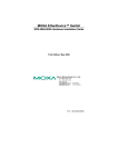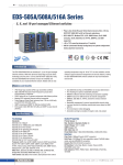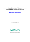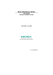
1
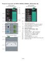
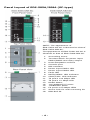
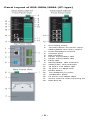
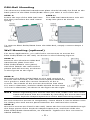
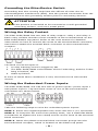
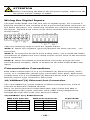
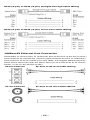
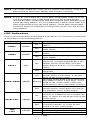
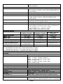
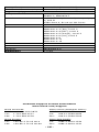
EDS-505A/508A Hardware Installation Guide Moxa EtherDevice™ Switch Ninth Edition, April 2014 2014 Moxa Inc. All rights reserved. P/N: 1802005000018 Package Checklist The Moxa EDS-505A/508A is shipped with the following items. If any of these items is missing or damaged, please contact your customer service representative for assistance. • • • • • • • 1 Moxa EtherDevice Switch (EDS-505A or EDS-508A) Hardware Installation Guide CD-ROM with User’s Manual and Windows Utility Warranty Statement RJ45 to DB9 Console port cable Protective caps for unused ports Panel Mounting Kit (optional—must be ordered separately) -2- Panel Layout of EDS-505A/508A (Standard) 1. 2. 3. 4. 5. 6. 7. 8. 9. 10. 11. 12. 13. 14. 15. 16. -3- Grounding screw Terminal block for power input PWR1/PWR2 and relay output Heat dissipation orifices Console port DIP switches Power input PWR1 LED Power input PWR2 LED Fault LED MSTR/HEAD: LED indicator CPLR/TA IL: LED indicator TP port’s 100 Mbps LED TP port’s 10 Mbps LED Model Name 10/100BaseT(X) ports Screw hole for wall mounting kit DIN-Rail kit Panel Layout of EDS-505A/508A (SC-type) NOTE: The appearance of EDS-505A-SS-SC is identical to that of EDS-505A-MM-SC. The appearance of EDS-508A-SS-SC is identical to that of EDS-508A-MM-SC. 1. 2. 3. 4. 5. 6. 7. 8. 9. 10. 11. 12. 13. 14. 15. 16. 17. 18. -4- Grounding screw Terminal block for power input PWR1/PWR2 and relay output Heat dissipation orifices Console port DIP switches Power input PWR1 LED Power input PWR2 LED Fault LED MSTR/HEAD: LED indicator CPLR/TAIL: LED indicator TP port’s 100 Mbps LED TP port’s 10 Mbps LED Model Name 10/100BaseT(X) ports 100BaseFX ports FX port’s 100 Mbps LEDs Screw hole for wall mounting kit DIN-Rail kit Panel Layout of EDS-505A/508A (ST-type) 1. 2. 3. 4. 5. 6. 7. 8. 9. 10. 11. 12. 13. 14. 15. 16. 17. 18. -5- Grounding screw Terminal block for power input PWR1/PWR2 and relay output Heat dissipation orifices Console port DIP switches Power input PWR1 LED Power input PWR2 LED Fault LED MSTR/HEAD: LED indicator CPLR/TAIL: LED indicator TP port’s 100 Mbps LED TP port’s 10 Mbps LED Model Name 10/100BaseT(X) ports 100BaseFX ports FX port’s 100 Mbps LEDs Screw hole for wall mounting kit DIN-Rail kit Mounting Dimensions Unit = mm (inch) -6- DIN-Rail Mounting The aluminum DIN-Rail attachment plate should already be fixed to the back panel of the EDS-505A/508A when you take it out of the box. STEP 1: Insert the top of the DIN-Rail into the slot just below the stiff metal spring. STEP 2: The DIN-Rail attachment unit will snap into place as shown. To remove EDS-505A/508A from the DIN-Rail, simply reverse Steps 1 and 2. Wall Mounting (optional) For some applications, you will find it convenient to mount the EDS-505A/508A on the wall, as shown in the following figures. STEP 1: Remove the aluminum DIN-Rail attachment plate from the EDS-505A/508A’s rear panel, and then attach the wall mount plates with M3 screws, as shown in the figures at the right. STEP 2: Mounting the EDS-505A/508A on the wall requires 4 screws. Use the EDS, with wall mount plates attached, as a guide to mark the correct locations of the 4 screws. The heads of the screws should be less than 6.0 mm in diameter, and the shafts should be less than 3.5 mm in diameter, as shown in the figure at the right. NOTE Before tightening the screws into the wall, make sure the screw head and shank size are suitable by inserting the screw into one of the keyhole-shaped apertures of the Wall Mounting Plates. Do not screw the screws in completely—leave about 2 mm to allow room for sliding the wall mount panel between the wall and the screws. STEP 3: Once the screws are fixed in the wall, insert the four screw heads through the large parts of the keyhole-shaped apertures, and then slide the EDS-505A/508A downwards, as indicated. Tighten the four screws for added stability. -7- ATEX Information 1. 2. 3. 4. 5. Certificate number DEMKO 08 ATEX 0712961X Ambient range (-40°C ≤ Tamb ≤ 75°C) Certification string (Ex nA nC IIC T4 Gc) Standards covered ( EN60079-0:2012, EN60079-15:2010) The conditions of safe usage: • These products must be mounted in an IP54 enclosure. • Install in an area of pollution degree 2 or less. • Use a conductor wire of size 0.2 mm² or greater. • PROVISIONS SHALL BE MADE, EITHER IN EXTERNAL TO THE APPARATUS, TO PREVENT THE RATED VOLTAGE BEING EXCEEDED BY THE TRANSIENTS DISTURBANCES OF MORE THAN 40 % Wiring Requirements WARNING The power for this product is intended to be supplied by a Listed Power Unit, with output marked LPS, and rated to deliver 12 to 45 VDC at a maximum of 600 mA. WARNING Safety First! Be sure to disconnect the power cord before installing and/or wiring your Moxa EtherDevice Switch. Calculate the maximum possible current in each power wire and common wire. Observe all electrical codes dictating the maximum current allowable for each wire size. If the current goes above the maximum ratings, the wiring could overheat, causing serious damage to your equipment. Please read and follow these important guidelines: • • • • Use separate paths to route wiring for power and devices. If power wiring and device wiring paths must cross, make sure the wires are perpendicular at the intersection point. NOTE: Do not run signal or communications wiring, and power wiring through the same wire conduit. To avoid interference, wires with different signal characteristics should be routed separately. Use the type of signal transmitted through a wire to determine which wires should be kept separate. The rule of thumb is that wiring that shares similar electrical characteristics can be bundled together. Keep input wiring and output wiring separate. It is strongly advised that you label wiring to all devices in the system, when necessary. -8- Grounding the EtherDevice Switch Grounding and wire routing help limit the effects of noise due to electromagnetic interference (EMI). Run the ground connection from the ground screw to the grounding surface prior to connecting devices. ATTENTION This product is intended to be mounted to a well-grounded mounting surface, such as a metal panel. Wiring the Relay Contact The EDS-505A/508A has two sets of relay output—relay 1 and relay 2. Each relay contact consists of two contacts of the terminal block on the EDS-505A/508A’s top panel. Refer to the next section for detailed instructions on how to connect the wires to the terminal block connector, and how to attach the terminal block connector to the terminal block receptor. The fault circuit will open if: 1. 2. 3. A relay warning event is triggered, OR The EDS-505A/508A is the Master of this Turbo Ring, and the Turbo Ring is broken, OR Start-up failure. If none of these three conditions is met, the fault circuit will remain closed. Wiring the Redundant Power Inputs The EDS-505A/508A unit has two sets of power inputs—power input 1 and power input 2. Top and front views of one of the terminal block connectors are shown below. Take the following steps to wire the redundant power inputs: STEP 1: Insert the negative/positive DC wires into the V-/V+ terminals. STEP 2: To keep the DC wires from pulling loose, use a small flat-blade screwdriver to tighten the wire-clamp screws on the front of the terminal block connector. STEP 3: Insert the plastic terminal block connector prongs into the terminal block receptor, which is located on the EDS’s top panel. -9- ATTENTION Before connecting the EDS to the DC power inputs, make sure the DC power source voltage is stable. Wiring the Digital Inputs The EDS-505A/508A unit has two sets of digital inputs, DI 1 and DI 2. Each DI consists of two contacts of the 6-pin terminal block connector on the EDS’s top panel. The remaining contacts are used for the EDS’s two DC inputs. Top and front views of one of the terminal block connectors are shown below. Take the following steps to wire the digital inputs: STEP 1: Insert the negative (ground)/positive DI wires into the ┴/I1 terminals. STEP 2: To keep the DI wires from pulling loose, use a small flat-blade screwdriver to tighten the wire-clamp screws on the front of the terminal block connector. STEP 3: Insert the plastic terminal block connector prongs into the terminal block receptor, which is located on the EDS-505A/508A’s top panel. Communication Connections EDS-508A models have 8 or 6 10/100BaseT(X) Ethernet ports, and 0 (zero) or 2 100BaseFX (SC/ST-type connector) fiber ports. EDS-505A models have 5 or 3 10/100BaseT(X) Ethernet ports, and 0 (zero) or 2 100 BaseFX (SC/ST-type connector) fiber ports 10/100BaseT(X) Ethernet Port Connection The 10/100BaseT(X) ports located on EDS’s front panel are used to connect to Ethernet-enabled devices. Next, we show pinouts for both MDI (NIC-type) ports and MDI-X (HUB/Switch-type) ports, and also show cable wiring diagrams for straight-through and cross-over Ethernet cables. 10/100Base T(x) RJ45 Pinouts MDI Port Pinouts Pin Signal 1 Tx+ 2 Tx3 Rx+ 6 Rx- MDI-X Port Pinouts Pin Signal 1 Rx+ 2 Rx3 Tx+ 6 Tx- - 10 - 8-pin RJ45 RJ45 (8-pin) to RJ45 (8-pin) Straight-Through Cable Wiring RJ45 (8-pin) to RJ45 (8-pin) Cross-Over Cable Wiring 100BaseFX Ethernet Port Connection Remember to connect the Tx (transmit) port of device I to the Rx (receive) port of device II, and the Rx (receive) port of device I to the Tx (transmit) port of device II. If you make your own cable, we suggest labeling the two sides of the same line with the same letter (A-to-A and B-to-B, as shown below, or A1-to-A2 and B1-to-B2). SC-Port Pinouts SC-Port to SC-Port Cable Wiring ST-Port Pinouts ST-Port to ST-Port Cable Wiring - 11 - ATTENTION This is a Class 1 Laser/LED product. To avoid causing serious damage to your eyes, do not stare directly into the Laser Beam. Turbo Ring DIP Switch Settings EDS-505A/508A series are plug-and-play managed redundant Ethernet switches. The proprietary Turbo Ring protocol was developed by Moxa to provide better network reliability and faster recovery time. Moxa Turbo Ring’s recovery time is less than 300 ms (Turbo Ring) or 20 ms (Turbo Ring V2) —compared to a 3- to 5-minute recovery time for commercial switches—decreasing the possible loss caused by network failures in an industrial setting. There are 4 Hardware DIP Switches for Turbo Ring on the top panel of EDS-505A/508A that can help setup the Turbo Ring easily within seconds. If you do not want to use a hardware DIP switch to setup the Turbo Ring, you can use a web browser, telnet, or console to disable this function. NOTE Please refer to the Turbo Ring DIP Switch section and Using Communication Redundancy section in User’s Manual for more detail information about the settings and usage of Turbo Ring and Turbo Ring V2. EDS-505A/508A Series DIP Switches The default setting for each DIP Switch is OFF. The following table explains the effect of setting the DIP Switch to the ON position. “Turbo Ring” DIP Switch Settings DIP 1 DIP 2 DIP 3 Reserved for ON: Enables this ON: Enables the future use. EDS as the Ring default “Ring Coupling” ports. Master. OFF: This EDS will not be the Ring Master. OFF: Do not use this EDS as the ring coupler. “Turbo Ring V2” DIP Switch Settings DIP 1 DIP 2 DIP 3 ON: Enables the ON: Enables this ON: Enables the default “Ring EDS as the Ring default “Ring Coupling Master. Coupling” port. (backup)” port. OFF: Enables the OFF: This EDS default “Ring will not be the Coupling Ring Master. (primary)” port. DIP 4 ON: Activates DIP switches 1, 2, 3 to configure “Turbo Ring” settings. OFF: DIP switches 1, 2, 3 will be disabled. DIP 4 ON: Activates DIP switches 1, 2, 3 to configure “Turbo Ring V2” settings. OFF: Do not use OFF: DIP this EDS as a ring switches 1, 2, 3 will be disabled. coupler. - 12 - NOTE You must enable the Turbo Ring function first before using the DIP switch to active the Master and Coupler functions. NOTE If you do not enable any of the EDS-505A/508A switches to be the Ring Master, the Turbo Ring protocol will automatically choose the EDS-505A/508A with the smallest MAC address range to be the Ring Master. If you accidentally enable more than one EDS-505A/508A to be the Ring Master, these EDS-505A/508A switches will auto-negotiate to determine which one will be the Ring Master. LED Indicators There are several LEDs on the EDS’s front panel. The function of each LED is described in the following table. LED Color PWR1 AMBER PWR2 AMBER FAULT RED MSTR/HEAD GREEN CPLR/TAIL GREEN 10M (TP) GREEN State Description Power is being supplied to power input On PWR1. Power is not being supplied to power Off input PWR1. Power is being supplied to power input On PWR2. Power is not being supplied to power Off input PWR2. When (1) a relay warning event is triggered, (2) EDS-505A/508A is the Master of this Turbo Ring, and the On Turbo Ring is broken, or (3) start-up failure. When a relay warning event is not Off triggered. When the EDS-505A/508A is set as the On Master of the Turbo Ring, or as the Head of the Turbo Chain. The EDS-505A/508A has become the Ring Master of the Turbo Ring, or the Blinking Head of the Turbo Chain, after the Turbo Ring or the Turbo Chain is down. When theEDS-505A/508A is not the Off Master of this Turbo Ring or is set as the Member of the Turbo Chain. When the EDS-505A/508A coupling function is enabled to form a back-up On path, or when it's set as the Tail of the Turbo Chain. Blinking When the Turbo Chain is down. When the EDS-505A/508A disables the Off coupling function, or is set as the Member of the Turbo Chain. On TP port’s 10 Mbps link is active. Blinking Data is being transmitted at 10 Mbps. Off TP Port’s 10 Mbps link is inactive. - 13 - LED Color 100M (TP) GREEN 100M (FX) GREEN State On Blinking Off On Blinking Off Description TP port’s 100 Mbps link is active. Data is being transmitted at 100 Mbps. TP Port’s 100 Mbps link is inactive. FX port’s 100 Mbps is active. Data is being transmitted at 100 Mbps. FX port’s 100 Mbps is inactive. Auto MDI/MDI-X Connection The Auto MDI/MDI-X function allows users to connect the EDS-505A/508A’s 10/100BaseTX ports to any kind of Ethernet device, without needing to pay attention to the type of Ethernet cable being used for the connection. This means that you can use either a straight-through cable or cross-over cable to connect the EDS-505A/508A to Ethernet devices. Fiber Ports The fiber ports are factory-built as either multi-mode or single-mode SC/ST connectors. Therefore, you should use fiber cables that have SC/ST connectors at both ends. When plugging the connector into the port, make sure the slider guide is positioned to the right side such that it fits snuggly into the port. Specifications Technology Standards Protocols MIB Forwarding and Filtering Rate Processing Type IEEE802.3, 802.3u, 802.3x, 802.1D, 802.1w, 802.1Q, 802.1p, 802.1X, 802.3ad IGMPv1/v2, GVRP, SNMPv1/v2c/v3, DHCP Server/Client, BootP, TFTP, SNTP, SMTP, RARP, GMRP, LACP, RMON, HTTP, HTTPS, Telnet, Syslog, DHCP Option 66/67/82, SSH, SNMP Inform, Modbus/TCP, LLDP, IEEE 1588 PTP, IPv6 MIB-II, Ethernet-Like MIB, P-BRIDGE MIB, Q-BRIDGE MIB, Bridge MIB, RSTP MIB, RMON MIB Group 1,2,3,9 148810 pps Store and Forward - 14 - Flow Control IEEE802.3x flow control, back pressure flow control Interface RJ45 Ports 10/100BaseT(X) auto negotiation speed, F/H duplex mode, and auto MDI/MDI-X connection 100BaseFX ports (SC/ST connector) RS-232 (RJ45) PWR1, PWR2, FAULT, 10/100M (TP port), 100M (Fiber Port), MSTR/HEAD and CPLR/TAIL Two relay outputs with current carrying capacity of 1A @ 24 VDC Master, Coupler, Turbo Ring, Reserve Two inputs with the same ground, but electrically isolated from the electronics • For state “1”: +13 to +30V • For state “0”: -30 to +3V • Max. input current: 8 mA Fiber Ports Console LED Indicators Relay Contact DIP Switches Digital Input Optical Fiber Multi-mode Wavelength Max. Tx Min. Tx Rx Sensitivity Link Budget Single-mode 1300 nm 1310 nm -10 dBm 0 dBm -20 dBm -5 dBm -32 dBm -34 dBm 12 dB 29 dB 5 km (a) Typical Distance 40 km (c) 4 km (b) Saturation -6 dBm -3 dBm a. using [50/125 μm, 800 MHz*km] cable b. using [62.5/125 μm, 500 MHz*km] cable c. using [9/125 μm, 3.5 PS/(nm*km)] cable d. using [9/125 μm, 19 PS/(nm*km)] cable Power Input Voltage Input Current (@24V) Connection Overload Current Protection Reverse Polarity Protection Mechanical Casing Dimensions Weight Installation Environment Operating Temperature Single-mode, 80 km 1550 nm 0 dBm -5 dBm -34 dBm 29 dB 80 km (d) -3 dBm 12 to 45 VDC, redundant inputs Max. 0.24A: (EDS-505A) Max. 0.26A: (EDS-508A) Max. 0.35A: (EDS-505A-MM, EDS-505A-SS) Max. 0.36A: (EDS-508A-MM, EDS-508A-SS) Two removable 6-pin terminal blocks Present Present IP30 protection, metal case 80.5 × 135 × 105 mm (W × H × D) 1.04 kg DIN-Rail, Wall Mounting (optional kit) 0 to 60°C (32 to 140°F), -40 to 75°C (-40 to 167°F ) for -T models - 15 - Storage Temperature Ambient Relative Humidity Regulatory Approvals Safety Hazardous Location EMI EMS Shock Freefall Vibration WARRANTY -40 to 85°C (-40 to 185°F) 5 to 95% (non-condensing) UL60950-1, UL 508, CSA C22.2 No. 60950-1, EN60950-1 UL/cUL Class I, Division 2, Groups A, B, C, and D. ATEX Zone 2, Ex nA nC IIC T4 Gc FCC Part 15, CISPR (EN55022) class A EN61000-4-2 (ESD), Level 2 EN61000-4-3 (RS), Level 3 EN61000-4-4 (EFT), Level 3 EN61000-4-5 (Surge), Level 3 EN61000-4-6 (CS), Level 3 EN61000-4-8 EN61000-4-11 EN61000-4-12 IEC60068-2-27 IEC60068-2-32 IEC60068-2-6 5 years Technical Support Contact Information www.moxa.com/support Moxa Americas: Toll-free: 1-888-669-2872 Tel: 1-714-528-6777 Fax: 1-714-528-6778 Moxa China (Shanghai office): Toll-free: 800-820-5036 Tel: +86-21-5258-9955 Fax: +86-21-5258-5505 Moxa Europe: Tel: +49-89-3 70 03 99-0 Fax: +49-89-3 70 03 99-99 Moxa Asia-Pacific: Tel: +886-2-8919-1230 Fax: +886-2-8919-1231 - 16 -