1
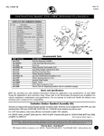
No.1409-IS
Rev N/C
4/05
Instruction Sheet For Tool #1409
Evo ( evolution) C ase B oring T ool
®
The JIMS EVO Case Boring Tool takes all the guess work out of boring EVO engine cases to accept up to
3-13/16” bore cylinders. This tool is designed to be used in a heavy-duty 15" drill press, or milling machine.
Note: Please read all instructions completely and thoroughly before performing any work.
IF YOU DO NOT KNOW WHAT YOU ARE DOING, DO NOT DO IT!
No information in this instruction sheet pertaining to motorcycle repair is represented as foolproof or even
altogether safe. Some people can ruin a mechanic’s vise with a tack hammer. Even something safe, done
incorrectly or incompletely can and will backfire.
You and only you are responsible for the safety of your repair work and for your understanding and application
with the use of repair equipment, components, methods and concepts.
Each and every step that this tool is designed to do must be carefully and systematically performed safely by
you. All information listed in this instruction sheet has been tested, re-tested and used daily in JIMS® Research
and Developement Department.
JIMS® IS NOT RESPONSIBLE FOR THE QUALITY AND SAFETY OF YOUR WORK.
®
Follow instructions in H.D. Service Manual for removal of engine for your year and model. With the engine removed from the frame
®
and safely mounted in one of JIMS No. 1006T motor stands, follow the engine dissasembly instructions in the service manual, including removal of the cylinder studs. Mask off all bearings and oil holes to prevent chips from contaminating those areas. Bolt cases togeth®
®
er with H.D. hardware using sequence and torque specs stated in H.D. service manual, except top center case bolt between cylinders.
Install this bolt last and torque to 50-90 in-lbs. maximum (Read Step 1).
Tools required for boring:
1/8”, 3/16", 1/4", & 5/16" Allen wrenches, 7/16” Wrench, Calipers, Torque wrench, 1/2" socket,
Cutting Fluid, Drill press or Milling machine.
555 Dawson Drive, Camarillo, CA 93012
Phone 805-482-6913 • Fax 805-482-7422
1
No.1409-IS
Rev N/C
4/05
Instruction Sheet For Tool #1409
INSTRUCTIONS
1.
Prior to boring your cases, you will need to determine
the Rockwell hardness your case hardware is. If your
hardware is under 30 RC, you may bore your cases
with your case bolts installed. If your hardware is
harder than 30 RC, you will need to clearance the top
center and top rear case bolts, (See Fig. 4). Damage
may occur to the tool cutters
if the above instructions
®
are not followed. JIMS is not liable for damaged tool
cutters.
When you bore your cases for larger bore sizes, you
may break out the tappet machining oil hole, (See Fig
1). You may need to re-plug and seal as required if
disturbed.
Assemble Engine Cradle (No.1, No.2, No.3) as shown
in Fig.2. Make sure all mating surfaces are clean.
3.
Place the Engine Case in the Cradle and rotate the
case so either the Front or Rear cylinder deck is horizontal and facing up. Fig.3
4. Install (2) lubed 1/4-20 SHCS (No.10) into the appropriate holes, depending on the spigot bore you are
modifying, in the alignment plate (No.3) as shown in
Fig.2. Do not tighten. Install (3) lubed 5/16-18 SHCS
(No.13) into the mounting plate (No.1) holes marked
with letter of the spigot bore you are modifying.
Using a 1/4” allen wrench snug all three 5/16-18
bolts, then torque to 13-15 ft. lbs. Once you have
tightened the 5/16-18 bolts, torque the 1/4-20 bolts
to 90-120 ft lbs. using a 3/16” allen wrench.
Fig.1
10
3
13
2.
2
5. Installing cutters:
22
11
9
1
21
Fig.2
NOTE: Boring head set-up shown is for reference only. Your setup will vary depending on cylinder bore diameter and
cylinder manufacturer. Instruction sheet is written for boring 3-5/8” bore cylinders. Again, if your cylinders are
made from a different manufacturer or you are machining
for other than a 3-5/8” bore, you will need to calculate
your cutter dimensions (see set-up sheet, page 5).
NOTE: JIMS® recommends removing no more than .125” (on
the diameter) of material at a time. Case machining may
require more than one pass and set-up of cutters to obtain
the desired bore.
Fig.3
CAUTION:
Fig.4
Once you have determined the cutter dimensions, install
the cutters in the boring head as shown in FIG. 5, FIG. 6
& FIG. 7. Using a 1/8” Allen wrench, adjust the adjustment screws (No. 1689) to set the cutters dimensions
from your calculations (FIG. 7). Use a caliper for accurate
measurements. Ensure that the cutters are held snug
against the adjusting screws as the lock down screws are
Wear safety glasses. Excessive force may damage parts!
555 Dawson Drive, Camarillo, CA 93012
Phone 805-482-6913 • Fax 805-482-7422 2
No.1409-IS
Rev N/C
4/05
Instruction Sheet For Tool #1409
tightened. Torque the lock down screws (in order shown,
FIG. 7) to 90 in./lbs. to secure the cutters in place.
Finish Cut Side
WARNING: If cutters are set beyond O4.09, the cutters
may come in contact with the I.D. of the locating
plate (1409-2), voiding the warranty of the 1409-2 Evo
Case Boring Tool.
Rough Cut
Side
(.03” Step)
Fig.6
6.
Setting Spigot depth:
Measure the length of your cylinders’ spigot and add
.03”-.06”. This will be the depth you need to bore your
cases to. (Example: If your spigot is 1.600”, add .03”-.06”
and your bore depth will be 1.630” + .03”/-.00”. Using a
1/8” allen wrench and a 7/16” wrench, set the boring
depth to the dimension as calculated above, as shown in
Fig. 8. Be sure to measure from the finish tool cutter to
the bottom of the locating plate (No. 5).
7.
Place a 1-1/2” - 2” wood black between the boring assembly plates. Mount the boring assembly onto the engine
case with (2) lubed 3/8-16 SHCS (No. 9). Make sure the
boring assembly is sitting flush on the engine case.
Using a 5/16” allen wrench, torque the mounting bolts to
18-20 ft. lbs.
8.
Place the case boring fixture onto a drill press or milling
machine table. Center the shaft of boring head (No. 4) in
chuck or collet.
NOTE: If using a chuck, be sure that the chuck jaws locate
on the flats of the boring head shaft.
Tighten the chuck or collet (depending on the machine
being used) and remove the wood block used to seperate
the boring assembly. Clamp the base (No. 2) to the drill
press table using the provided holes if possible. If you are
unable to use the provided holes, be sure to clamp the fixture using C-Clamps or comparible clamps. Before running
the machine, lube the two guide dowels with a light oil and
run the quill up and down to make sure the boring assembly is not binding
19
17
16
12
12
18
6
16
7
20
4
14
14
15
8
9
9
5
Fig.5
DIMENSIONS FOR 3-5/8” BORE
3.670
(.220)
1st
2nd
LOCK DOWN SCREWS
2 PLC No.1689
2nd
1st
Tighten these screws
first.
2nd
Tighten these screws
second.
Finish Cut Side
Rough Cut Side
2nd
1st
(.155)
3.605
CAUTION:
Fig.7
CAUTION: DO NOT STRIKE CUTTERS AGAINST
CRANKCASE When checking to make sure the tool action
is correct, be aware not to strike the cutters against the
crankcase while the machine is not running. Damage may
result to the tool and crankcase.
NOTE: If the cradle assembly is not sitting flat to the
machine table, adjust the table (or head) flat before
clamping down the assembly.
9. Set the machines speed to approximately 600-800
RPM’s. Before running the machine, make sure that
the quill is at the top of it’s travel. Start the machine
to make sure that the head and/or table are not
vibrating. If no vibrations occur, the RPM’s may be
increased. If vibrations
occur, the RPM’s will need to
®
be reduced. JIMS has found that 600-800 RPM’s is
Wear safety glasses. Excessive force may damage parts!
555 Dawson Drive, Camarillo, CA 93012
Phone 805-482-6913 • Fax 805-482-7422
3
No.1177-IS
Rev N/C
4/05
Instruction Sheet For Tool #1409
Depth adjustment
screw
the best when using a drill press, although results can
vary from your set-up and machine. Not all drill presses and milling machines are made the same.
CAUTION: It is recommended that you use a well
maintained and dependable machine for this type of
work. If you use a drill press or milling machine that
is not up to normal standards, you risk the chance of
damage to your work and injury to yourself. This is
why we recommend you use a safe and well maintaned drill press or milling machine. Make sure your
machine is in good working order before starting any
project.
ALWAYS WEAR SAFETY GLASSES OR OTHER FACE AND
EYE PROTECTION SUCH AS FULL FACE SHIELD.
Fig.8
®
JIMS is not responsible for damage, injury or your work!
10. Make sure your eye and/or face protection is on.
Double check to make sure you followed the procedures correctly and your work is properly clamped to
the table. Start boring with slow, even pressure while
applying cutting fluid (slower feed rate will yield a
cleaner finish) until the boring assembly stop bottoms
Note: Place a 1-1/2" to 2" wood block
out. Shut down the machine and wait until it comes
between boring assembly plates to
to a complete stop. Slowly retract the boring assemkeep top plate from dropping.
bly until the cutters clear the case. Hold the quill up
and replace the wood block. Remove the boring
assembly from the case.
CAUTION: DO NOT PUSH IN OR LIFT OUT CUTTER TOO FAST
OR ABRUPTLY WHILE BORING, DOING SO COULD RESULT
IN DAMAGE TO YOUR WORK OR INJURY TO YOURSELF!
Fig.9
CAUTION: BEFORE RE-ASSEMBLY OF YOUR ENGINE MAKE
SURE THE INSIDE OF THE CASE , SPIGOT BORE AND ALL
INTERIOR AND EXTERIOR POCKETS AND HOLES ARE FREE
OF ANY CONTAMINANTS AND DE-BURRED. STOP, DOUBLE
CHECK AND THEN TRIPLE CHECK. YOU DO NOT WANT
ANY CONTAMINANTS LEFT INSIDE. DOING SO CAN AND
WILL CAUSE PPRE-MATURE WEAR AND DAMAGE.
NOTE: When re-assembling cases, tighten case bolts to factory specs except top center case bolt between cylinders. Install this bolt last after you have cylinders and heads installed and torqued to H.D.® specs. Apply
Hylomar, or equivalent, sealer to shoulder of top center case bolt and torque to 50-90 in-lbs. maximum.
®
JIMS IS NOT RESPONSIBLE FOR YOUR WORK!
SO PLEASE USE YOUR BEST JUDGEMENT AND ALWAYS
DOUBLE AND EVEN TRIPLE CHECK YOUR WORK.
DOING SO WILL HELP ENSURE A POSITIVE EXPERIENCE AND OUTCOME.
CAUTION:
Wear safety glasses. Excessive force may damage parts!
555 Dawson Drive, Camarillo, CA 93012
Phone 805-482-6913 • Fax 805-482-7422
4
No.1409-IS
Rev N/C
4/05
Instruction Sheet For Tool #1409
SET-UP SHEET
FOR 3-5/8” BORE
“A” .220
FINISH
U.S.A.
ROUGH
U.S.A.
X
R
XX
#1177-4
“T”
.155 “B”
(BORING HEAD DIAMETER)
O3.45
“S”
(CYLINDER SPIGOT DIAMETER)
O3.87
Step 1: Measure your cylinder spigot diameter.
(S) and add .02”.
Step 2: Measure the boring head diameter (T)
as shown above. Subtract boring head diameter
from answer obtained in step 1, this is your
overall clearance (D).
Step 3: Divide your overall clearance by 2. This
is your “A” dimension.
D = OVERALL CLEARANCE
S = CYLINDER SPIGOT DIAMETER
T = BORING HEAD DIAMETER
C = CASE BORING DIAMETER
Step 4: Subtract .065” from your “A” dimension.
This is you “B” dimension.
FORMULA
Step 1: S + .02” =C
Step 2: C - T =D
Step 3: D / 2 =”A”
Step 4: “A” - .065” = ”B”
EXAMPLE
3.87”+.02”= 3.89”
3.89”-3.45”= .44”
.44”/ 2= .22”
.22”-.065”= .155”
Fig.9
CAUTION:
Wear safety glasses. Excessive force may damage parts!
555 Dawson Drive, Camarillo, CA 93012
Phone 805-482-6913 • Fax 805-482-7422
5
No.1409-IS
Rev N/C
4/05
Instruction Sheet For Tool #1409
PARTS LIST
NO.
QTY
1
2
3
4
5
6
7
8
9
10
11
12
13
14
15
16
17
18
19
20
21
22
23
1
1
1
1
1
1
1
1
6
2
4
2
3
2
6
2
1
1
1
1
3
3
1
TITLE OR DESCRIPTION
PART NUMBER
MOUNTING PLATE
BASE PLATE
ALIGNMENT PLATE, CASE BORING TOOL, EVO
BORING HEAD, BORING ASSEMBLY
LOCATING PLATE, CASE BORING, EVO
SUPPORT PLATE, BORING ASSEMBLY
SHIELDED BEARING, 7/8” x 2” x 9/16” (1640-2RS)
PULL OUT DOWEL, 1/2” x 3-1/2”
3/8-16 x 1” SHCS
1/4-20 x 1” SHCS
DOWEL PIN, 1/4” x 3/4”
BUSHING, .502” I.D. x .75” O.D. x .75” LONG
5/16-18 x 1” SHCS
TOOL BIT, AL, CEMENTED CARBIDE, 3/8”
1/4-28 x 1/2” SET SCREW
WASHER, 1/4”, SAE
1/4-20 x 1-3/4” Set Screw
1/4-20 JAM NUT
1/4-20 x1/2”, BHCS
DOWEL PIN, 1/2” x 3-1/2”
3/8” AN WASHER
3/8-16 x 1-1/4” SHCS
INSTRUCTION SHEET
1177-1
1177-2
1409-1
1177-4
1409-2*
1177-6
8149
1685
1686
2133
8093
1681
2405
1688 **
1689
1683
1679
1682
8090
1680
1265
1036
1409-IS
*1409-2 is not covered under warranty if locating plate displays cutter marks from improper adjustment.
** 1688 Non-serviceable wear item, no warranty.
WARRANTY
All JIMS® parts are guaranteed to the original purchaser to be free of manufacturing defects in material and workmanship for a period
of six (6) months from the date of purchase. Merchandise that fails to conform to these conditions will be repaired or replaced at JIMS® option
the parts are returned within the six (6) months warranty period or within ten (10) Days thereafter.
In the event warranty service is required, the original purchaser must call or write JIMS® immediately with the problem. Some problems
can be rectified by a telephone call and need no further course of action. A part suspected of being defected must not be replaced by a dealer
without prior authorization by JIMS®. If it is deemed necessary for JIMS® to make an evaluation to determine whether the part is defective, it
must be packaged properly to prevent further damage and be returned prepaid to JIMS® with a copy of the original invoice of purchase and a
detailed letter outlining the nature of the problem, how the part was used and the circumstances at the time of failure. If after an evaluation has
been made by JIMS® and the part was found to be defective, repair, replacement or credit will be granted.
1.
2.
3.
4.
5.
ADDITIONAL WARRANTY PROVISIONS
JIMS® shall have no obligation in the event a JIMS® part is modified by person or organization.
JIMS® shall have no obligation if a JIMS® part becomes defective in whole or in part as a result of improper installation, improper
maintenance, improper use, abnormal operation, or any other misuse or mistreatment of the part.
JIMS® shall not be liable for any consequential or incidental damages resulting in the failure of a JIMS® part, the breach of any
warranties, the failure to deliver, delay in delivery, delivery in nonconforming condition, or for any other breach of contract or
duty between JIMS® and a customer.
JIMS® parts are designed exclusively for use in Harley-Davidson® motorcycles. JIMS® shall have no warranty or liability obligation if JIMS® part is used
in any other application.
Any parts or tool replaced by JIMS® becomes the property of JIMS® and will not be returned under any circumstance.
555 Dawson Drive, Camarillo, CA 93012
Phone 805-482-6913 • Fax 805-482-7422
6