1
FACULDADE DE ENGENHARIA DA UNIVERSIDADE DO PORTO
The Augmented Reality Systems in a
Maintenance of Equipment tutorial context
Sofia Alexandra Gonçalves Rodrigues
Master in Informatics and Computing Engineering
Supervisor: António Augusto de Sousa (Professor Associado)
Co-Supervisor: Maria Teresa Restivo (Investigadora Principal)
1st February, 2015
The Augmented Reality Systems in a Maintenance of
Equipment tutorial context
Sofia Alexandra Gonçalves Rodrigues
Master in Informatics and Computing Engineering
Approved in oral examination by the committee:
Chair: Jorge Barbosa (Professor Auxiliar)
External Examiner: Paulo Dias (Professor Auxiliar)
Supervisor: António Augusto de Sousa (Professor Associado)
Co-Supervisor: Maria Teresa Restivo (Investigadora Principal)
____________________________________________________
1 st February, 2015
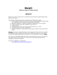
Abstract
Augmented Reality’s development as a concept and available related techniques have been
stabilizing throughout the years, allowing numerous AR applications to appear in several areas
such as medical, design, maintenance and repair, annotation and visualization, robot path
planning, military aircraft and entertainment which has received the most attention.
While many of those areas have shown the advantages AR can bring, there are still some
loopholes that need to be filled. Assembly and maintenance of equipment, for instance, has been
a thoroughly investigated subject of study in AR.
Many applications have been developed which demonstrate the benefits of AR in assembly
tasks, but this dissertation’s main innovative point is to allow the creation of AR assembly
tutorials using the same AR system that allows its tutorial execution. The creation of tutorials
would be carried out through the use of a manual 3D scanner, in order to carefully pinpoint each
location of the assembly components.
Several virtual Objects were included in the application to aid in pointing out and guiding
the user, to focus his attention in the right area. This application also aimed at a high level of
customization in the interface, specifically the positioning and content of Menus.
Ten users participated in an evaluation which required the creation of a simple tutorial.
Through this evaluation, it was possible to see how quickly the user adjusted to the interface's
logic and easily customized the virtual objects. The calibration between the Augmented Reality
System and the 3D Digitizer was also a positive point due to its simplicity, which allowed to see
how intuitive and effective the 3D Digitizer was in positioning virtual Objects and interacting
with the interface. Overall, the results demonstrated that this authoring tool was effective and
intuitive whether when using the 3D Digitizer or the keyboard shortcuts as an interaction tool.
Keywords: augmented reality, maintenance and assembly, tutorial creation, procedural
instructions
i
Resumo
O desenvolvimento da Realidade Aumentada como um conceito e as técnicas disponíveis
relacionadas têm vindo a estabilizar ao longo dos anos, permitindo o aparecimento de uma
numerosa quantidade de aplicações de Realidade Aumentada em áreas como a medicina, design,
manutenção e reparação, anotação e visualização, planeamento de trajectória de robôs, aviação
militar e entretimento que tem recebido mais atenção.
Embora muitas dessas áreas tenham demonstrado as vantagens da Realidade Aumentada,
ainda existem algumas aberturas por preencher. A montagem e manutenção de equipmento, por
exemplo, tem sido um tema de estudo investigado minuciosamente.
Várias aplicações têm sido desenvolvidas que demonstram os benefícios da Realidade
Aumentada em tarefas de montagem, mas o ponto principal de inovação desta dissertação focase em permitir a criação de Tutoriais de montagem utilizando Realidade Aumentada através do
mesmo sistema de Realidade Aumentada que permite a execução do tutorial. A criação de
tutoriais seria efectuada através da utilização de um digitalizador 3D, de modo a identificar
cuidadosamente a localização da próxima peça a ser montada.
Vários objectos virtuais foram incluídos na aplicação como apontadores e guias para o
utilizador, de forma a focar a sua atenção no local correcto. Esta aplicação também teve como
objectivo um alto nível de customização na interface, mais especificamente no posicionamento
e contéudo dos menus.
Dez utilizadores participaram numa avaliação que exigiu a criação de um tutorial simples.
Através desta avaliação, foi possível analisar a rapidez de ajuste do utilizador à lógica da
interface e a facilidade de customização dos Objectos virtuais. A calibração entre o Sistema de
Realidade Aumentada também foi um ponto positivo devido à sua simplicidade, o que permitiu
analisar a eficácia e intuitividade do digitalizador 3D no posicionamento de Objectos virtuais e
na interacção com a interface. No geral, os resultados demonstraram que esta aplicação foi
eficaz e intuitiva independentemente da escolha de ferramenta de interacção do utilizador
(digitalizador 3D ou atalhos de teclado).
Palavras-chave: realidade aumentada, manutenção e assemblagem, criação de tutoriais,
instruções processuais
ii
Acknowledgments
While words can hardly suffice to express my gratitude, I'd still like to thank my advisors,
Prof. A. Augusto de Sousa and Prof. M. Teresa Restivo, for their everlasting patience and
knowledge that they bestowed upon me, as many times as it was necessary at times to repeat the
information. I'd like to thank Prof. J. Miguel Leitão also for his assistance with
OpenSceneGraph that allowed me to speed up the development to a pace that hardly seemed
possible before.
To my family, I can only say that I couldn't ask for a better one. Thank you for letting me
work at my pace, even when it didn't seem the most fitting choice. Your support even when
patience was lacking in me or the small gestures in the early mornings mean the world to me.
It's the little things that truly matter the most.
Cathy, I couldn't call you any other way. For always sticking with me, no matter what or
how long it goes between any interactions, you are a most precious best friend to me and always
will be. Your artsy self was of course, highly appreciated for this dissertation and saved me for
sure. To Liliana, a dear friend who is always willing to listen and help, I doubt my gratitude will
be enough for your proofreading and advice, but I couldn't let it go unspoken. I hope to never
lose contact with you. To João and Carlota, you two most likely have no idea how the time
spent with you saved my sanity. When my brain was mostly nonexistent, the nights we spent
playing, talking and relaxing brought it back so easily it still amazes me. For supporting me and
bringing me up when I most needed it.
Conny, how you stood by my side all these years still amazes me. You inspire me to strive
harder and to not give up. I am truly happy to be considered a best friend to you. Adi, while life
brought us through many painful hurdles, I'm glad in the end contact was never truly broken. I
hope to one day see you and Conny somewhere in Europe! You two made me grow in a way
that I truly believe helped me during my dissertation.
Lastly, I'd like to thank the researchers, technicians and students involved with the lab for
their always present help and for those moments past 19h30 when one's sanity was reaching the
limit, but it was still possible to laugh before finally going home.
Sofia Rodrigues
iii
Contents
1 Introduction............................................................................................................................. 1
1.1 Motivation and Objectives................................................................................................. 1
1.2 Dissertation Structure......................................................................................................... 2
2 State of the Art......................................................................................................................... 3
2.1 Reality-Virtuality Continuum............................................................................................. 3
2.2 History of Augmented Reality........................................................................................... 4
2.3 Augmented Reality Systems.............................................................................................. 8
2.3.1 Display Devices & Tracking...................................................................................... 9
2.3.2 User Interfaces.......................................................................................................... 12
2.3.3 Software................................................................................................................... 13
2.4 Augmented Reality Applications..................................................................................... 15
2.4.1 General Applications................................................................................................ 15
2.4.2 Assembly and Maintenance Applications................................................................ 16
2.5 Summary.......................................................................................................................... 20
3 Technological Discussion......................................................................................................
3.1 Evaluated Solutions..........................................................................................................
3.1.1 Augmented Reality Libraries...................................................................................
3.1.2 Graphical User Interfaces.........................................................................................
3.2 Summary..........................................................................................................................
22
22
23
26
26
4 Conception of a Tutorial System based on Augmented Reality........................................ 28
4.1 Tutorial Structure............................................................................................................. 28
4.2 Architecture...................................................................................................................... 30
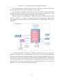
4.3 Augmented Reality System Components......................................................................... 31
4.4 Possible Solutions............................................................................................................. 31
4.5 Summary.......................................................................................................................... 33
5 Implementation of a Tutorial System based on Augmented Reality................................ 34
5.1 Solution............................................................................................................................ 34
5.1.1 Application Configuration........................................................................................ 36
5.1.2 ALVAR & 3D Digitizer Calibration........................................................................ 38
5.1.3 User Interface & 3D Digitizer Interaction................................................................ 41
5.1.4 Application Features................................................................................................ 42
iv
5.1.4.1 Virtual Helping Objects................................................................................. 44
5.2 System Evaluation............................................................................................................ 46
5.3 Summary.......................................................................................................................... 51
6 Conclusions and Future Work............................................................................................. 52
6.1 Goal Satisfaction.............................................................................................................. 52
6.2 Future Work..................................................................................................................... 53
Appendix A: Application Manual...........................................................................................
A.1 Purpose of this Manual..................................................................................................
A.2 Application Configuration.............................................................................................
A.2.1 Configuration.........................................................................................................
A.2.2 Lights.....................................................................................................................
A.2.3 Camera Calibration................................................................................................
A.2.4 Marker Data...........................................................................................................
A.3 ALVAR-Haptic Calibration..........................................................................................
A.3.1 Menu Interaction & Interface................................................................................
A.4 Tutorial Structure...........................................................................................................
A.4.1 Types of Objects....................................................................................................
A.4.1.1 Arrows............................................................................................................
A.4.1.2 3D Models......................................................................................................
A.4.1.3 Text................................................................................................................
A.5 Creating & Editing a Tutorial........................................................................................
A.6 Playing/Running a Tutorial...........................................................................................
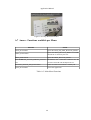
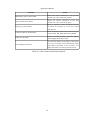
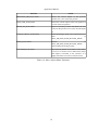
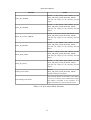
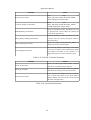
A.7 Annex - Functions available per Menu.........................................................................
54
54
55
55
56
56
57
58
58
60
62
62
63
63
63
67
68
Appendix B: Tutorial System Application Guide.................................................................. 87
Appendix C: Tutorial System Application Questionnaire.................................................... 90
References................................................................................................................................. 92
v
List of Figures
Figure 2.1: Reality-Virtuality Continuum...................................................................................... 4
Figure 2.2: Sutherland's Head-mounted three dimensional display............................................... 5
Figure 2.3: KARMA – Steven Feiner, Blair MacIntyre, Dorée Seligmann................................... 6
Figure 2.4: Rekimoto's 2D Matrix Markers................................................................................... 6
Figure 2.5: MARS - Touring Machine........................................................................................... 7
Figure 2.6: AR System Components.............................................................................................. 9
Figure 2.7: Square and Circular Markers..................................................................................... 10
Figure 2.8: Optical see-through HMD (Azuma 1997)................................................................. 11
Figure 2.9: Video see-through HMD (Azuma 1997)................................................................... 11
Figure 2.10: Doorlock Assembly................................................................................................. 17
Figure 2.11: Pathomaree and Charoenseang................................................................................ 18
Figure 2.12: Liverani et al............................................................................................................ 18
Figure 2.13: Zauner et al.............................................................................................................. 19
Figure 2.14: ARMAR................................................................................................................... 19
Figure 2.15: Yuan et al................................................................................................................. 20
Figure 4.1: Tutorial Structure....................................................................................................... 29
Figure 4.2: High-level Architecture............................................................................................. 30
Figure 4.3: Marker-based System using ARToolkit..................................................................... 32
Figure 4.4: Markerless System..................................................................................................... 33
Figure 5.1: Solution Architecture................................................................................................. 35
Figure 5.2: Components Interaction............................................................................................. 36
Figure 5.3: 1st Calibration Method.............................................................................................. 38
Figure 5.4: Main Menu Screenshot.............................................................................................. 41
Figure 5.5: Menu Flow................................................................................................................. 43
Figure 5.6: Visualization Menu Screenshot................................................................................. 43
Figure 5.7: New Or Edit Menu - Screenshot................................................................................ 44
Figure 5.8: Edit Object Menu Flow.............................................................................................. 45
Figure 5.9: 3D Model, 2D, 3D and 3D Cone Arrows.................................................................. 45
Figure 5.10: 2D Text.................................................................................................................... 46
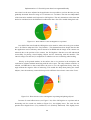
Figure 5.11: How intuitive was the 3D Digitizer as a pointer?.................................................... 48
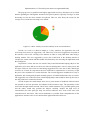
Figure 5.12: How effective was the 3D Digitizer in pointing and placing objects?.................... 48
Figure 5.13: How would you rate the usability of the editing system?........................................ 49
Figure 5.14: How would you rate the usability of the overall interface?..................................... 50
vi
Figure A.1: Tutorial Structure......................................................................................................
Figure A.2: Main Menu Screenshot.............................................................................................
Figure A.3: Menu Flow................................................................................................................
Figure A.4: Edit Object Menu Flow.............................................................................................
Figure A.5: HUD Text Menu Flow..............................................................................................
Figure A.6: First Step of the First Instruction..............................................................................
Figure A.7: 3D Model, 2D, 3D and 3D Cone Arrows.................................................................
Figure A.8: 2D, 3D and 3D Cone Arrow Menu Flow..................................................................
Figure A.9: Edit 3D Model Menu Flow.......................................................................................
Figure A.10: Play Menu Screenshot.............................................................................................
vii
61
63
64
65
65
66
66
67
67
68
List of Tables
Table 3.1: Augmented Reality Libraries......................................................................................
Table 5.1: Arrow Properties.........................................................................................................
Table 5.2: Text Properties............................................................................................................
Table A.1: Arrow Properties........................................................................................................
Table A.2: Text Properties...........................................................................................................
Table A.3: Main Menu Functions................................................................................................
Table A.4: New Or Edit Menu Functions....................................................................................
Table A.5: Move Instruction Menu Functions.............................................................................
Table A.6: New Or Edit Instruction Menu Functions..................................................................
Table A.7: Move Step Menu Functions.......................................................................................
Table A.8: New Or Edit Step Menu Functions............................................................................
Table A.9: Move Object Menu Functions....................................................................................
Table A.10: New Object Menu Functions....................................................................................
Table A.11: Edit 2D Arrow Menu Functions...............................................................................
Table A.12: Transform Object Menu Functions..........................................................................
Table A.13: Reposition Menu Functions......................................................................................
Table A.14: Animation Menu Functions......................................................................................
Table A.15: Edit 3D Arrow Menu Functions...............................................................................
Table A.16: Edit 3D Cone Arrow Menu Functions.....................................................................
Table A.17: Edit 3D Model Menu Functions...............................................................................
Table A.18: Edit HUD Text Menu Functions..............................................................................
Table A.19: Edit Box Type Menu Functions...............................................................................
Table A.20: Edit Text Menu Functions........................................................................................
Table A.21: Edit 2D Text Menu Functions..................................................................................
Table A.22: Open Menu Functions..............................................................................................
Table A.23: Play Menu Functions................................................................................................
Table A.24: Help Menu Functions...............................................................................................
viii
25
45
46
62
63
68
69
70
71
72
73
74
75
76
77
77
78
79
80
81
82
83
84
85
85
86
86
Abbreviations
6DoF
AA
AM
AR
CAD
CAVE
GUI
HUD
HMD
OS
RV
SDK
VR
Six Degrees of Freedom
Augmented Assembly
Augmented Maintenance
Augmented Reality
Computer-Aided Design
Cave Automatic Virtual Environment
Graphical User Interface
Head-up Display
Head-mounted Display
Operative System
Reality-Virtuality Continuum
Software Development Kit
Virtual Reality
ix
1 Introduction
Augmented Reality’s development as a concept and available related techniques have been
stabilizing throughout the years, allowing numerous AR applications to appear in several areas
such as medical, design, maintenance and repair, annotation and visualization, robot path
planning, military aircraft and entertainment which has received the most attention.
While many of those areas have shown the advantages AR can bring, there are still some
gaps that can be filled. Assembly and maintenance of equipment, for instance, has been a
thoroughly investigated subject of study in AR.
An assembly task typically has two phases, depending on the degree of familiarity with the
object to be assembled. The first phase consists in the reading and comprehension of the
assembly instructions, and the second phase, the task execution. There are a few known
problems such as the time spent in the task and the learning curve for new tasks (Tang et al.
2003) which can be reduced through the use of AR, therefore improving the worker’s
performance (Neumann and Majoros 1998). Through immersing the user, AR can also
potentiate a better interpretation of the instructions, therefore reducing the number of errors and
can optimize the project through the comprehension of the difficulty of the assembly phase.
Authors such as Henderson and Feiner (2009) proved the benefits of AR to task
performance and several projects were developed that tested AR’s effectiveness compared to
other visualization and annotation methods (Baird and Barfield 1999, Reinhart and Patron 2003,
Wiedenmaier et al. 2003, Sausman et al. 2012, Hou and Wang 2013, Hou et al. 2013) . Their
results showed, for example, that using AR decreased the learning curve and accelerated the
assembly of the objects, reducing unnecessary body movements as well.
1.1 Motivation and Objectives
From the projects evaluated, all of them focused on the utilization of AR and evaluating its
benefits and effectiveness through a tutorial that varied in its complexity. None of the projects
researched focused on the creation of an AR assembly or maintenance tutorial using the AR
1
Introduction
system itself, which is what this dissertation plans to approach, along with testing its utilization
to prove it brings an added bonus to the user.
Therefore, the objectives for this dissertation will be (1) to research and analyze
applications in the same context – applications related to assembly and maintenance of
equipment – that are based in AR, (2) to develop a tridimensional structure of medium
complexity that will serve as a base to support the AR studies that will be performed in a
tutorial context, (3) to specify, implement and evaluate a tutorial system, based in AR, which
will, through its usage, facilitate the learning of the previously referred structure. And finally,
(4) the main activities and sequence of processes will also be determined, in the context of a
tutorial elaboration, to therefore allow the creation of a perspective towards the implementation
of a tutorial creation system for the developed system.
1.2 Dissertation Structure
Besides the introduction, this report also contains five more chapters. In chapter 2, it is
described Augmented Reality, by briefly introducing the Reality-Virtuality Continuum,
followed by the Augmented Reality systems where it is explained its typical components. This
subsection also details the types of devices, user interfaces and software that were researched
during the development of the state of the art. Chapter 2 also contains general Augmented
Reality applications and the related work to this dissertation. The latter expands mainly towards
the applications related to assembly and maintenance and related works that prove the benefits
found when AR is used in assembly and maintenance tasks.
In chapter 3, the solutions evaluated for the Augmented Reality Software and the
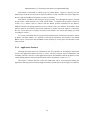
Graphical User Interface are discussed. Chapter 4 explains how the application's conception
occurred and the conclusions reached in terms of structures required and components for the
system. Chapter 5 builds on the conception detailed in the previous chapter and describes the
possible solutions and final solution found for the application. In comparison with Chapter 4,
section 5.2 uses a similar architecture Figure with the components now filled in. The calibration
research is detailed in this chapter as well, along with the user interface interaction and the
features of the application. This chapter also details how the creation of tutorials was tested and
preliminarily evaluated. Finally, in chapter 6, the dissertation is concluded with the goals met
and possible future work.
2
2 State of the Art
Augmented reality in maintenance and assembly is a widely investigated field, in which a
thorough research was required in order to find the best approach to this problem.
As such, in this chapter, in the first section it is explained what the Reality-Virtuality
Continuum is as an introduction to Augmented Reality and its History, which is explained in the
second section. It is then followed by the third section, which details the components of an
Augmented Reality system and explains the types of tracking, display devices, user interfaces
and software that were found and analyzed. Several software possibilities were researched and
the most seemingly fitting will be later compared in Chapter 3. Their advantages and
disadvantages found will be explained along with the reason for choosing the software system
the dissertation's application utilized.
Finally, Augmented Reality applications in general and the related work to this
dissertation – applications related to assembly and maintenance of equipment – are also
analyzed in a section of its own, with a few applications not quite related to maintenance or
assembly of equipment also detailed in the second subsection due to the relevance of some
technological aspect or development strategy. The problems found in this area are described
per application and the gaps that allow this dissertation to exist are also fully explained.
2.1 Reality-Virtuality Continuum
The Reality-Virtuality Continuum was defined by Milgram and Kishino (1994) in order to
classify the various aspects of what they defined as Mixed Reality (MR). Their goal was to
separate a variety of environments that were being associated with Virtual Reality, despite not
providing total immersion and complete synthesis. They explained that these environments fall
in a virtuality continuum, where real and virtual worlds are merged in different ways ranging
from Real Environments to Virtual Environments.
3
State of the Art
Figure 2.1: Reality-Virtuality Continuum
The Figure above details the taxonomy described, with Real Environment being the world
as we know it on one extreme of the scale and Virtual Reality on the other extreme. The Real
Environment in this taxonomy consists of only real objects and can include, for example, what
can be observed through a video display of a real-world scene. Another example would be to
visualize the same scene directly, instead of through any electronic display system. Virtual
Reality, as the opposite of Real Environment, consists of only virtual objects and an example of
it would be a computer graphic simulation within a CAVE (Cave Automatic Virtual
Environment). Accordingly to Milgram and Kishino, between Real Environments and Virtual
Reality is the Mixed Reality which is composed of environments where real world and virtual
world objects are presented together within a single display. In Augmented Virtuality, the
primary world is the virtual world being augmented by real objects. Finally, in Augmented
Reality, the primary world is the real world being augmented by virtual objects. Augmented
Reality will be defined in more detail in the next section along with its history and examples.
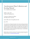
2.2 History of Augmented Reality
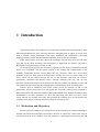
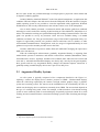
Augmented Reality (AR) had its start in 1968 when Prof. Ivan Sutherland invented the first
Head-mounted Display (HMD) (Sutherland 1968). It later became referred to as the “Sword of
Damocles” (Van Krevelen and Poelman 2010), since it had to be hanged from the ceiling by an
adjustable pole, for it was uncomfortable to use and far too heavy for the user to support it with
his own strength. The system was primitive and the graphics that comprised the virtual
environment surrounding the user were merely wireframe rooms shown through miniature
CRTs, such as the third picture below. It had two types of head sensors, a mechanical sensor as
shown in the center picture below and an ultrasonic sensor.
4
State of the Art
Figure 2.2: Sutherland's Head-mounted three dimensional display
It was only in 1992 however that the Augmented Reality term was coined by Caudell and
Mizell in their work performed at Boeing that conveyed wiring instructions for aircraft
assembly (1992). They described Augmented Reality as an overlaying of computer-presented
material on top of the real world through the use of an HMD. They also discussed the
advantages of Augmented Reality versus Virtual Reality where the former requires less
processing power due to needing less rendering. The need for stronger research in the
registration requirements that are needed to align real and virtual worlds was also acknowledged
by them.
Two major contributions to Augmented Reality happened in 1993, with Rosenberg's
Virtual Fixtures and the KARMA 1 from Feiner et al. At the U.S Air Force Armstrong Labs,
Rosenberg developed one of the first known Augmented Reality Systems, Virtual Fixtures,
where he studied the benefits of Augmented Reality on a workspace in direct and remotely
manipulated tasks by using an overlay of augmented sensory information. He confirmed that,
despite the normal decrease in performance when comparing in-person manipulation tasks to
remote tasks, through the use of overlays in remote tasks, the performance was restored to a
value closer to in-person tasks. It was also discovered that using the overlays in person could
double the human performance of the task (Rosenberg 1995).
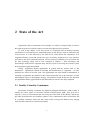
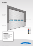
KARMA (Knowledge-based Augmented Reality for Maintenance Assistance) was
developed by Feiner et al. in the Computer Graphics and Interfaces Lab of the University of
Columbia and allowed the user to perform a simple maintenance task on a laser printer (1993).
By attaching Logitech 3D Trackers to key components of the printer, they were able to monitor
the trackers' position and orientation as the user visualized the instructions through a seethrough head-mounted display as shown in the Figure below. It was one of the first assembly
and maintenance applications that used augmented reality and demonstrated its benefits.
1
http://monet.cs.columbia.edu/projects/karma/karma.html
5
State of the Art
Figure 2.3: KARMA – Steven Feiner, Blair MacIntyre, Dorée Seligmann
The first of the two widely accepted Augmented Reality definitions was by Milgram and
Kishino, where they defined Augmented Reality as a part of the Reality-Virtuality Continuum
(RV), which ranges from a completely real environment to a completely virtual one as defined
in the previous section in further detail (1994).
The second widely accepted definition of Augmented Reality appeared in 1997. According
to Azuma’s commonly accepted definition, augmented reality (AR) can be defined as “a system
or visualization technique that fulfills three main features: (1) a combination of real and virtual
worlds, (2) real time interaction and (3) accurate 3D registration of virtual and real objects”
(Azuma 1997).
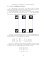
One of the first marker systems was presented by Rekimoto which allowed camera
tracking with six degrees of freedom (6DoF) (1998). The 2D matrix markers were squareshaped barcodes (see Figure 2.4) and acted as the reference point for registering information
in real world images.
Figure 2.4: Rekimoto's 2D Matrix Markers
His method allowed the identification of 2 16 (65536) different objects through the barcode
markers, making it a cheap Augmented Reality system since the markers could be printed and
allowed attachment of virtual objects to real world objects at virtually no cost. Despite the
combination of visual markers and a video camera, the placement of objects by the developer
was not a simple process. Since it required accurate 3D position measurements, Rekimoto also
developed an authoring tool that determined the position of a 3D point in the real world based
6
State of the Art
on two 2D images where the 2D matrix code is visible. Through a stereo vision method, the 3D
position was determined based on the pair of 2D points given and the virtual object was placed.
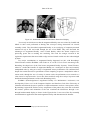
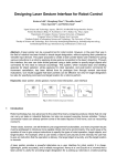
The first mobile Augmented Reality system (MARS) began in 1997 with the Touring
Machine (Feiner et al.). The MARS unit provided campus information through a see-through
head-worn display with an integral orientation tracker, assisted the user in finding places and
allowed him to query the system about items of interest, such as buildings and statues
surrounding him. The unit also possessed a hand-held computer with a stylus and a touchpad
interface, a backpack holding the computer, differential GPS and a digital radio for wireless
web access. The other projects associated to MARS were the Mobile Journalist's Workstation
(Hollerer, Feiner, and Pavlik 1999), UIs for Indoor/Outdoor Collaboration (Höllerer et al. 1999)
and the MARS Authoring Tool (Sinem and Feiner 2003).
Figure 2.5: MARS - Touring Machine
It was only in 1999 that an Augmented Reality system would reach the open-source status
and become available to the general public. Kato and Billinghurst developed ARToolkit (1999),
a marker-based tracking system that became one of the most well-known tools for Augmented
Reality and gave rise to many other systems.
Thomas et al. developed AR-Quake, an augmented reality extension to the desktop game
Quake (2000). The initial setup was based on a six degrees of freedom (6DoF) tracking system
that used GPS, a digital compass and a vision-based tracking system that used fiducial markers.
Over the years, the backpack that the users equipped on their backs became smaller and lighter,
but it is still a system impossible to mass produce due to its heavy cost of equipment. The game
is playable indoors or outdoors, allowing users that are playing inside in the desktop computer
to cooperate or play against users that are outdoors. Actions of the outdoor users are performed
by movements in the real environment and through the simple input interface.
The first see-through Augmented Reality system for tracking 3D markers on a phone was
developed by Mathias Möhring et al. and supported the detection and differentiation of different
3D markers (Mohring, Lessig, and Bimber 2004). The integration of rendered 3D graphics into
7
State of the Art
the live video stream was performed through a weak perspective projection camera model and
an OpenGL rendering pipeline.
In 2008, Mobilizy launched Wikitude 2 on the first android smartphone, an application that
combines GPS and compass data with entries from the Wikipedia. With the launch of Google's
mobile operating system it was possible to create the augmented reality application, Wikitude
World Browser, that overlays information in the real-time camera view of the smartphone.
Also in 2008, Metaio presented a commercial mobile AR museum guide that combined
technologies such as markerless tracking, hybrid tracking an Ultra-Mobile-PC (Miyashita et al.
2008). The markerless tracking was performed through the tracking of natural features. The ARguide was possible to use by any museum visitor and was available during a six-month
exhibition on Islamic Art. They proved that their usage of full 6-DOF Augmented reality as a
support for appreciating artwork was possible without restrictions such as markers or other
environmental instrumentations. Through their work, the usage of Augmented Reality in route
guidance was proved as another possible area for the field.
In 2009, ARToolkit was ported to Adobe Flash (FLARToolkit 3) bringing the open-source
SDK to the web browser.
With the technological advancements, gradually Augmented Reality is migrating from
marker-based systems to markerless and mobile context-aware methods (Barandiaran, Paloc,
and Graña 2010, Álvarez, Aguinaga, and Borro 2011, Dedual, Oda, and Feiner 2011, Klein and
Assis 2013). And while head-mounted displays are mostly only a novelty for the general public,
their growth and the way Augmented Reality changes the human-Computer interaction is
gradually turning wearable display devices into a part of our daily lives.
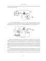
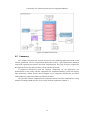
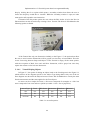
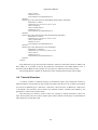
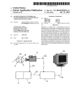
2.3 Augmented Reality Systems
An AR system is typically composed of the components detailed in the Figure 2.6,
requiring a camera, the display device (monitor, projector or HMD – Head-mounted display)
where the video image captured by the camera is merged with the graphics image, a graphics
system and a tracking system. The camera can be immobilized or be controlled by the user, in
which case the display device would most commonly be an HMD. The area tracked depends on
the type of tracking being used, where for example, a fiducial marker vision-based tracking
system is most commonly used to track and display 3D spatially registered content for a small
working area and a natural features vision-based tracking system is able of tracking much larger
areas.
2
3
http://www.wikitude.com/
http://www.libspark.org/wiki/saqoosha/FLARToolKit/en
8
State of the Art
Figure 2.6: AR System Components
The following subsections will explain in further detail which types of display devices,
interfaces and types of tracking are associated to Augmented Reality Systems. The types of
markers existent will also be detailed along with the types of tracking. Finally, the last
subsection will specify the software systems researched and evaluated.
2.3.1 Display Devices & Tracking
Augmented Reality can be used indoor or outdoor and according to Zendjebil, I., et al
(2008), AR can be classified as marker-based or markerless. Marker-based techniques utilize
2D fiducial markers artificially planted in the real environment and that are easy to detect and
distinguish along with being less demanding in processing power.
Existing techniques for detecting and identifying markers in the context of computer vision
include correlation, digital or topological methods. Comparisons have been made between the
marker processing algorithms and the digital code approach was concluded to be the most
robust and reliable (Köhler, Pagani, and Stricker 2011).
Correlation techniques require additional files to store the known patterns to be able to
measure the degree of correlation of a pattern found inside an image and match it successfully.
An example of a system using such a technique would be ARToolkit. Digital methods however,
do not require additional files to match the binary code from the marker with a non redundant
ID for identification. Lastly, topological methods extract markers from the image topology and,
along with correlation methods, tend to be the least robust (Costanza and Robinson 2003, Fiala
2005).
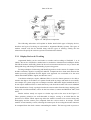
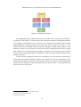
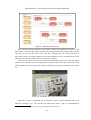
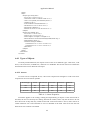
Marker trackers mostly use square or circular tags such as the ones in the Figure 2.7.
These geometry primitives are well-detectable in images, serving as an initial hint for the
presence of a marker. While square tags allow the marker's content to be accessed using only
homography and the camera pose computed from the vertices tends to be unique, circular
markers are not bound by vertices, allowing the camera pose for accessing the marker content to
be computed from the whole contour surrounding the marker. The later tag tends to possess a
9
State of the Art
more robust detection towards occlusions. However, circular tags require the intrinsic data of
the camera to always be known and there is always a pose ambiguity when only a single marker
is used (Chen, Wu, and Wada 2004, Koehler, Pagani, and Stricker 2010). Possible examples of
square and circular markers can be seen in the Figure below. The first marker is used in
ARToolkit (correlation method) and it demonstrates that it is an object easy to identify by its
black and white regions, also allowing the pose estimation of the objects to be calculated
through the asymmetry of the content inside the black region of the marker. The middle image
is a marker used in ALVAR, identifiable by a binary code. The image on the right is a circular
marker used by PrizaTech4.
Figure 2.7: Square and Circular Markers
Markerless techniques, on the other hand, rely on natural features existing in the real
environment, such as corners, edges or line segments. A widely growing markerless technique
is the Edge-based, which uses 3D CAD Models provided to compare with the 2D information
extracted from the scene and is used in applications outlined in the assembly and maintenance
applications section.
Currently, marker-based technique is the most used in the research performed. However it
should be noted that this pose estimation method requires the placement of artificial markers a
priori in the scene, which isn’t always possible.
Both techniques will be described further in the Software section in the augmented reality
systems found and evaluated.
As for the display devices used in Augmented Reality, desktop-based applications
typically use a monitor and a stationary camera. However, for a higher degree of immersion and
interaction by the user, HMD displays can be used instead which would also possibly increase
the mobility of the application if the camera was the only hindrance. An HMD is a Headmounted display device, meaning a wearable device, that the user can utilize to see the real
world and the virtual content. The HMD can be either an optical see-through or a video seethrough.
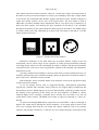
An optical see-through HMD doesn't capture the real world unlike a video see-through. It
displays the virtual objects through the optical combiners on an image plane in front of the
user's eyes, merging them with the real world. The optical combiners tend to be partially
reflective and partially transmissive, so that the user can visualize both the virtual objects that
4
http://www.prizatech.com
10
State of the Art
are bounced off the combiners and the real world. An example of a optical see-through system
can be seen in the Figure 2.8.
Figure 2.8: Optical see-through HMD (Azuma 1997)
A video see-through HMD utilizes one or two cameras mounted on the head gear to
capture images of the real world that are then later combined with the virtual objects to create
the augmented view. An example of a video see-through HMD can be seen in the Figure 2.9.
Figure 2.9: Video see-through HMD (Azuma 1997)
While video see-through systems face challenges such as resolution, due to having to
capture the real world as well, and safety since they are essentially closed-view HMDs that
when turned off make the user effectively blind. They also offer a higher degree of flexibility in
merging both virtual and real worlds which can produce environments that are more compelling
than those produced by optical systems (Rolland and Fuchs 2000, Juan and Calatrava 2011).
Both have their advantages and disadvantages and face similar problems in registration and
calibration which have been a point of interest over the years in research related to Augmented
Reality.
For this dissertation's application, an HMD would be the most appropriate choice to allow
the user to move around the workplace and visualize the objects integrated in each step of each
instruction of the tutorial he is working with. A markerless approach would also seem the most
appealing for the user in terms of setup difficulty since it would not require markers. However a
11
State of the Art
marker-based currently provides more stability when considering the components required for
this application, as it will be discussed further in Chapter 3.
2.3.2 User Interfaces
Carmigniani et al. divided the Augmented Reality interfaces into four possible groups:
Tangible interfaces, Hybrid interfaces, Collaborative interfaces and Multimodal interfaces
(2011).
Tangible interfaces, as the name suggests, allow direct interaction with the real world
through the use of real, physical objects and tools. For Augmented Reality, there are several
examples demonstrating the use of this interface, such as the VOMAR application developed by
Kato et al. which allows an user to move around virtual objects in the AR interface by using a
real paddle (2000). Since virtual objects are always drawn on top of the real world images, the
authors opted for minimizing the hand occlusion with transparency cues.
Another example of a tangible AR user interface is the metaDESK which explores the
physical instantiation of interface elements from the graphical user interface paradigm by giving
physical form to windows, icons, handles, menus and controls (Ullmer and Ishii 1997).
Tangible user interfaces in Augmented Reality can also include the use of gloves (Cooper
et al. 2004) or wristbands (Feldman et al. 2005).
Hybrid Augmented Reality interfaces are composed of a mixture of different yet
complementary interfaces which allow the possibility of interaction through a wide range of
interaction devices. Through a flexible infrastructure, the input and output devices as well as the
interaction techniques that use them are easily accommodated in a hybrid user interface. This
causes an increase in the number of operations the system can support beyond the conventional
ones, even possibly allowing users to specify new operations at run time (Feng, Duh, and
Billinghurst 2008).
Sandor et al. developed a hybrid user interface that allowed the user to manipulate objects
through various interaction techniques, such as whole-body interaction by using a dance pad,
manual input devices (knobs, sliders and bend sensors), and game controllers (2005). As
defined above for hybrid user interfaces, they support interactive end-user reconfiguration of the
mapping between devices, objects and operations. Their system used a head-tracked, seethrough display and provided overlaid visual and auditory feedback when the system was being
reconfigured.
Another example of a Hybrid Augmented Reality user interface would be the balloon
selection project developed by Benko and Feiner (2007). They developed a 3D selection
technique that utilized a hybrid touch-sensitive interface and demonstrated the possibilities of
multi-finger and multi-touch techniques for improving interactions on and above those surfaces.
Their technique decomposed a 3DOF precise positioning task into a set of 2DOF and 1DOF
positioning tasks on the tabletop and reduced hand fatigue while allowing the users to gain
accuracy.
Collaborative Augmented Reality interfaces utilize multiple displays to support remote and
co-located activities. The former type of activity coordinates efficiently with Augmented
12
State of the Art
Reality through the integration of multiple devices with multiple locations that allow the
enhancement of teleconferences (Barakonyi, Fahmy, and Schmalstieg 2004). These interfaces
can also be applied to medical applications to perform diagnostics, surgery or routine
maintenance. The latter type of activity requires 3D interfaces to improve the collaboration of
the physical workspace and has as an example the Studierstube project and related framework
(Schmalstieg, Fuhrmann, and Hesina 2000, Schmalstieg et al. 2002). This project aims at
bridging multiple user interface dimensions through Augmented Reality and features multiple
users, contexts, locales, applications, 3D-windows, hosts, display platforms and operating
systems.
Multimodal Augmented Reality user interfaces combine two or more user input modes,
such as speech, touch, natural hand gestures or gaze with real objects in a coordinated manner.
These types of interfaces aim to offer an expressive, transparent, efficient, robust and highly
mobile human-computer interaction (Carmigniani et al. 2011) and allow the user to switch the
input mode to one better suited to a particular task or setting.
An example of this type of user interface is the MIT's sixth sense wearable gestural
interface WUW (Mistry, Maes, and Chang 2009). This interface seeks to bring information
away from paper and computer screens through the use of a tiny projector and a camera
mounted on a hat or worn as a pendant. It sees what the user sees and augments surfaces, walls
and physical objects through natural hand gestures, arms movement or through interaction with
the object itself. Lee et al. also developed a multimodal interaction system that utilized the user's
gaze information to interact with the Augmented Reality environment (Lee et al. 2010). The
wearable Augmented Reality annotation system was composed of an optical see-through HMD,
a camera and an eye tracker.
The user interface for this dissertation's application will be a tangible interface since,
despite the keyboard shortcuts that will be available for the menu interface, the user will most
commonly not begin using the application through the shortcuts, but rather using a 3D Digitizer.
This interaction between the user and the application will be explained in Chapter 4.
2.3.3 Software
Several well-known AR software platforms were developed by research groups such as the
Human interface Technology Laboratory (HIT) from Washington University, the Computer
Graphics and Interfaces Lab from Columbia University and the VTT Technical Research Centre
of Finland, which allowed the development of specific-purpose AR applications.
These platforms, which provide basic algorithms and implementation knowledge in
various specialized problems, have examples such as ALVAR, ARTag, ARToolkit and
Studierstube that provide the user with an easy-to-use tool, therefore allowing anyone who has
AR or no AR background to quickly develop AR applications from scratch.
This section will be mostly focused on detailing the development systems investigated that
were available for Windows, although some will also have mobile options available. There were
13
State of the Art
many more such as Catchoom 5, Cortexica6, D'Fusion7 and Layar8 that were only available for
mobile platforms and were therefore not the main target of this research due to the use of the
manual 3D Digitizer making the application indoor based and stationary.
ARToolkit9 (Kato and Billinghurst 1999), is one of the examples of marker-based
platforms that this investigation will discuss in larger detail and is the most well-known tool that
has been widely used for AR applications. It has an open-source and free platform version that
allows the tracking of pre-designed markers to recognize different targets on which the virtual
objects can be superimposed. While the ARToolkit free version is no longer updated, it gave
rise to many other platforms based on its source-code, such as ARToolkitPro, NyARToolkit (a
multi-platform and OS) and ARToolkitPlus. ARToolkitPro10 is the commercial version of
ARToolkit by (ARToolworks) which provides natural features tracking that the open-source
version does not, along with a more robust tracking algorithm. It is also available as a mobile
version for iOS and Android. ARToolKitPlus was one of the successors of ARToolkit and was
created by (Wagner and Schmalstieg 2007) based on ARToolkit’s and ARTag’s source-code. It
brought many performance improvements over the original ARToolkit and was succeeded by
Studierstube tracker11.
ALVAR12, which was developed by the VTT Technical Research Centre of Finland, also
allows marker-based applications as the ones described above and markerless through features
in the environment or templates given to the application. It was based on ARToolkit as well,
and its last update was in 2012. It was designed with flexibility in mind and is independent of
any graphical libraries, allowing its easy integration in existing applications. It provides highlevel tools and methods for the creation of augmented reality applications with a few lines of
code. It also includes interfaces for all of its low-level tools and methods, which allows the
creation of alternative solutions and entirely new algorithms by the user.
ARTag (Fiala 2005), on the other hand, is no longer available due to licensing. It was
originally created by Mark Fiala from the Computational Video Group of the Institute for
Information Technology, and was also based on ARToolkit. Goblin XNA 13, from the Columbia
University, initially allowed the use of ARTag to create augmented reality games for windows
and xbox, but switched to ALVAR due to licensing issues detailed above.
On a commercial level, companies like Metaio have released an SDK 14 with several
licensing options available, ranging from free to full-rights, and which provide similar options
to the ones above, but on a wider scale of tracking possibilities. Unlike the previously
mentioned libraries, Metaio SDK allows both marker-based and markerless AR applications to
5
6
7
8
9
10
11
12
13
14
http://catchoom.com/product/craftar/augmented-reality-and-image-recognition-sdk/
http://www.cortexica.com/
http://www.t-immersion.com/products/dfusion-suite/dfusion-pro
https://www.layar.com/products/creator/
http://www.hitl.washington.edu/artoolkit/
http://www.artoolworks.com/
http://studierstube.icg.tugraz.at/handheld_ar/stbtracker.php
http://virtual.vtt.fi/virtual/proj2/multimedia/alvar/index.html
http://goblinxna.codeplex.com/
http://www.metaio.com/sdk/
14
State of the Art
be developed for free with a watermark. It was also the only SDK found that allowed 3D-model
based tracking.
Robocortex15 offers two SDKs, Rox Tracking SDK and Rox Odometry SDK, but only the
later is for Augmented Reality Applications. It only allows the use of natural features of the
referenced images to track and position the objects.
ARPA16, Qualcomm Vuforia17 and Xloudia18 are examples of SDKs that can only be
utilized in Windows through their Unity plugins, however the later is a commercial SDK only
with no free version and it merely allows image and movie tracking through natural features.
All three can be utilized in iOS and android. ARPA offers, through its unity plugin only
available for the pro version, the automatic detection of images which represent natural markers
and the display of any kind of multimedia content over them in real time. And Qualcomm
Vuforia offers the following features through its unity plugin: image targets, cylinder targets to
track objects such as a can of Coca-Cola, multi targets, user defined targets to allow the user to
choose his own marker, smart terrain, cloud recognition to recognize targets located in a cloud
database, text recognition, frame markers and virtual buttons.
The libraries that will be discussed and evaluated in Chapter 3 are ALVAR, ARToolkit and
Metaio SDK. They were tested as a possible incorporation to the application and the results of
the evaluation will be further discussed in the Augmented Reality Libraries subsection of
Chapter three.
2.4 Augmented Reality Applications
Augmented Reality applications first appeared in the military, industrial and medical areas
and were mostly confined to researches that never reached the general public. As the years
passed, open-source and commercial Augmented Reality systems began to appear and spread
the use of augmented reality to other areas such as entertainment, edutainment, design,
navigation, touring, personal assistance, among many others.
The first subsection of this section will discuss some general areas of applications and the
second subsection will give a stronger focus to the assembly and maintenance area due to being
the focus of this dissertation. It will analyze the applications in detail to compare with this
dissertation's focus.
2.4.1 General Applications
Augmented Reality's benefits and advantages were applied in several areas besides the
targeted area for this dissertation, maintenance and assembly. In the educational field,
Augmented Reality can be used as a complement in various ways. Markers can be embedded in
the students' textbooks or other educational reading material to provide them with additional
15
16
17
18
http://www.robocortex.com/index.php/sdk
http://arpa-solutions.net/en/ARPA_SDK
https://developer.vuforia.com/resources/sdk/
http://www.xloudia.com/tech/
15
State of the Art
information in the form of text, graphics, video and audio (Medicherla, Chang, and Morreale
2010, Chen and Tsai 2012, Di Serio, Ibáñez, and Kloos 2013). It can also serve as an alternative
way to visualize parts or systems of the human body (Blum et al. 2012) and mathematical and
geometric concepts in a collaborative manner (Kaufmann and Schmalstieg 2003). Augmented
Reality also benefits remote education by allowing students and instructors to share an
Augmented Reality environment and providing the students the opportunity to interact and
collaborate actively (Ying 2010).
Besides the educational field, Augmented Reality is also used in the medical field where it
can be used to provide surgeons with additional information that can be directly overlaid on the
patient's body during surgeries and other interventional procedures (Marescaux et al. 2004,
Nicolau et al. 2005, Nicolau et al. 2011). It can also aid in rehabilitation by, for example,
providing the patient with a virtual three-dimensional limb visualization that demonstrates the
movement that must be performed (Klein and Assis 2013).
In areas such as tourism and sightseeing for example, Augmented Reality can enhance the
user's experience by providing location-based information such as simulations of historical
events or a look into the past of the location and how it evolved (Hollerer, Feiner, and Pavlik
1999). It can also provide additional information and guidance in urban environments or
museums (Feiner et al. 1997, Miyashita et al. 2008) and can be used to reconstruct cultural
heritages, allowing visitors to visualize and learn about the ancient architecture and customs
(Vlahakis et al. 2002).
Augmented Reality is widely used in commerce as well for advertising and promoting
brands or products in an interactive manner. Above all, it is a technology that is gradually being
acknowledged for its benefits in a wide variety of areas, which is aiding in the development of
its effectiveness and overall growth.
2.4.2 Assembly and Maintenance Applications
Assembly instructions, drawings or schematics are often detached from the equipment,
creating an attention split in the worker’s focus between the instructions and the parts being
assembled which consumes valuable time, especially when the instructions are not conveniently
placed relative to the operators’ workspace. Some of the detriments of switching focus between
the paper instructions and the workplace can be reduced productivity, increased assembly times
and errors, repetitive motions and strain injuries (Ong, Yuan, and Nee 2008).
AR allows the display of information in the user’s field of view, therefore reducing
possible motion injuries, decreasing the time spent and improving the task performance. It
allows the worker to fully concentrate on the assembly task, not needing to switch his attention
and body position as he is working.
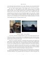
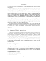
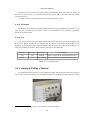
It was proven that AR can be used effectively in assembly sequence planning and
evaluation. Reiners et al. (1999) delineate a demonstrator for the task of door lock assembly (see
Figure 2.10) in a car door to teach users how the door lock is assembled into the car door.
Raghavan et al. (1999) developed an AR-based mixed prototyping method for assembly
16
State of the Art
evaluation that allowed a human to be guided by a multimedia augmentation to assemble an
industrial object.
Figure 2.10: Doorlock Assembly
Baird and Barfield (1999) developed a system to evaluate the effectiveness of wearable
augmented reality displays in assembly tasks. Their proposed task consisted in the assembly of a
computer motherboard by fifteen subjects and the instructions were seen in a paper manual, a
computer screen, an opaque augmented reality display or a see-through augmented reality
display. Their variables for evaluation were the time of assembly and number of assembly
errors, plus a usability questionnaire. The preferred device was the see-through display;
however there were many dependent variables that the authors chose to not isolate and may
have influenced their results, such as the differences in comfortableness provided by the HMDs
used, how strong the contrast was and how easy it was to read with. There was also no
registration of text instructions associated to the actual object when using AR; instead, the text
instructions were seen unattached to anything in specific and near the motherboard.
Nevertheless, the augmented reality display devices were still chosen in favor of the paper
manual and the computer screen.
Stork and Schubö (2010) also investigated the benefits of AR and spatial cueing in
assembly tasks. Their results showed that tasks using contact analog highlighting extracted the
most benefits and improvements over all in task performance, reduction of performance times,
eye fixations as well as increased velocity and acceleration of reaching and grasping
movements. Tang et al. (2003) developed a simple lego assembly to test the relative
effectiveness of AR instructions in an assembly task. Their results indicated that overlaying 3D
instructions on the assembly task reduced the error rate by 82%, particularly helping in
diminishing cumulative errors. They also demonstrated that the mental effort required for the
task was reduced through the use of AR.
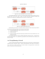
Pathomaree and Charoenseang (2005) developed an AR assembly training system to
intensify the skill transfer in assembly tasks. Their experimental results showed that the AR
training assembly system increased the speed of assembly of the user when transferring from
AR to non-AR. It could also reduce assembly completion times as well as the number of
assembly steps.
17
State of the Art
Figure 2.11: Pathomaree and Charoenseang
Recently, Hou et al. (2013) developed an AR System animated prototype for assembly
tasks, using a lego model as the assembly and experimental tester task. Their results
demonstrated that the AR system yielded shorter task completion times, less assembly errors,
and lower total task load. The learning curve of novice assemblers was also reduced and the task
performance which was relevant to working memory was increased when using AR training.
In the marker-based applications, Liverani et al. (2004) demonstrated that AR can be
integrated with a CAD assembly software and a wearable computer system for checking and
evaluating assembly sequence and interactive validation. A sample of their work can be found
in Figure 2.12.
Figure 2.12: Liverani et al.
Salonen et al. (2007) proposed a system for a 3D wooden puzzle assembly using
ARToolkit (see Figure 2.13). The system was fixed, simple and it functioned in an intuitive
manner. It mainly had the goal of serving as a demonstration to the industry of the capabilities
of AR and receive feedback on its advantages and disadvantages. Zauner et al. (2003)
developed an AR-assisted step-by-step furniture assembly system, where ARToolkit was used
for tracking and recognition of assembly components.
18
State of the Art
Figure 2.13: Zauner et al.
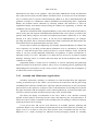
Platonov et al. (2007) described a solution for AR based repair guidance through the use of
a markerless CAD based tracking system which was able to handle different illumination
conditions during the tracking stage, partial occlusions and rapid motion (see Figure 2.14).
Starting in 2007, Feiner and Henderson, from the Computer Graphics and User Interface
Laboratory at Columbia University, began developing a series of prototypes to evaluate the
benefits of AR in maintenance and repair tasks and whether it improved task performance. Their
latest publication associated to ARMAR was in 2011 where they focused on the psychomotor
phase of a procedural task (Henderson and Feiner 2011).
Figure 2.14: ARMAR
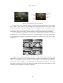
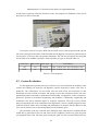
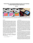
On a more interactive level, Yuan et al. (2008) developed an AR-based assembly guidance
system using a virtual interactive panel and an interaction pen that allows the user to easily
proceed through a pre-defined assembly sequence without needing any markers attached on the
assembly components (see Figure 2.15).
19
State of the Art
Figure 2.15: Yuan et al.
A considerable amount of applications have been currently developed, however its totality
was not discussed here. Most AR assembly systems are currently based on pre-defined markers,
with different patterns for each assembly component in order to properly track them (Raghavan,
Molineros, and Sharma 1999, Liverani, Amati, and Caligiana 2004, Hou and Wang 2013). One
of AR’s challenges is to be able to determine when, where, and what virtual information to
display in the augmented world during the assembly process. There is also an issue with
requiring at least a partial understanding of the surrounding assembly scene, which currently is
only available through feature tracking methods.
2.5 Summary
In this chapter, the Reality-Virtuality Continuum and Augmented Reality were defined,
along with Augmented Reality system components, including display devices, possible tracking
types and user interfaces. They were explained in as much detail as possible to allow the related
applications’ value to this dissertation to be clearly understood.
It was also demonstrated that over the years, the areas where Augmented Reality could
enhance performance or contribute to a fuller experience have been increasing and allowing the
amount of research and investment to grow in a considerable manner.
As for the related applications to this dissertation, it was shown in this chapter that the
applications found mainly focused on the utilization of tutorials and the benefits that AR can
provide to maintenance and assembly tasks, in terms of reducing eye and head movement and
increasing focus on the task. To the best of our knowledge, there are no approaches that allow
creation and use of tutorials.
As such, the focus of this dissertation is to implement an innovative approach that allows
the creation of tutorials through the use of the AR system, and also allows their use.
20
State of the Art
Further detailing in regards of the technological research that was required for this
dissertation and implementation will be discussed in the following chapters.
21
3 Technological Discussion
Before and during the development of the application, several possibilities were evaluated
for the required components. As such, this chapter will detail the choices found for each
component, their characteristics and explain how they were evaluated and discarded.
The possibilities evaluated were for the Augmented Reality Library and the Graphical
Interfaces. The former occurred before any sort of application development started, while the
later occurred during development also.
3.1 Evaluated Solutions
The components that required an analysis and investigation were the Augmented Reality
Library and the Graphical Interfaces.
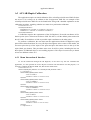
The requirements for the Augmented Reality Library differed based on the tracking type.
Libraries, such as ALVAR and Metaio, that allow markerless tracking, had different features to
be evaluated that could weigh in its advantages or disadvantages when compared to ARToolkit
that only contained marker-based tracking.
For the marker-based tracking, the existence of a multimarker implementation was
necessary to increase robustness to occlusion so that even if one marker is obscured, another
may be visible, and to improve pose-estimation accuracy since in a multimarker set, all the
marker corners are used to calculate the pose which means that the markers effectively cover a
larger optical angle and reduce the numerical error. The multimarker tracking principle bases
itself on a set of markers that are defined based on their relative positions. By having at least
one of those markers visible, it is possible to compute the position of the marker set in the
camera's coordinate system.
Both types of tracking, marker-based and markerless, were tested in a variety of lighting
conditions and marker positions (object position for the markerless tracking that Metaio
possesses), and also in their pose-estimation stability, tracking speed, how many markers it is
possible to track at the same time and in how complete marker occlusion is handled.
22
Technological Discussion
For the Graphical interfaces, the possibility of using it in a multi-threaded application
where the main thread did not need to be directly associated with running the interface was a
requirement. The main thread would have to run the video capture and marker tracking at all
times, making it impossible to do so if it is waiting for user input.
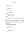
3.1.1 Augmented Reality Libraries
The software systems that were evaluated were ALVAR, ARToolkit and Metaio SDK. As
previously described, the open-source version of ARToolkit allows marker-based AR
applications and is no longer being updated, but the author of this document had access to it in a
subject she attended and is therefore more familiarized with it. There is also a commercial
version of ARToolkit, but that was not evaluated nor considered in table 3.1.
Metaio SDK was included in this evaluation due to its 3D CAD Tracking and the evaluated
ALVAR version here is the one available for Windows and Linux (there is another mobile SDK
version, but it is not available to the public). All other libraries found either required Unity Pro,
were commercial versions or did not meet the required parameters in marker-based tracking.
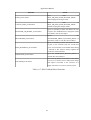
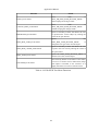
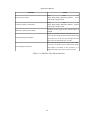
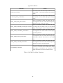
The table in page 25 compares the three Augmented Reality Libraries.
ARToolkit is a multi platform library that offers marker-based tracking in an user
accessible manner. It also offers camera calibration, the ability to use any square marker
patterns as long as they follow the black square design and doesn't have a steep learning curve.
It has a simple graphic library based on GLUT 19 and a fast rendering based on OpenGL 20.
Overall it is a good starting approach to small Augmented Reality projects. However, the lack of
support such as 3D Model Loaders and user interface components make this library less
approachable for bigger Augmented Reality projects.
Metaio SDK allows the creation of marker-based or markerless AR applications. The types
of tracking available are fiducial tracking, sensor-based tracking, markerless tracking, instant
tracking, QR/barcodes or a dummy. Fiducial tracking has three types of markers available: ID
markers, Picture markers or LLA (Latitude, Longitude and Altitude) markers. Sensor-based
tracking can be done through GPS coordinates or orientation of the device. Markerless tracking
has three types of markers available: a 2D Image, a 3D Map and a CAD Model. Instant tracking
allows the user to take a snapshot of the camera stream and use it as a markerless image
tracking reference in 2D space. Instant 3D tracking stands for creation of the point cloud (3D
map) of the scene and immediately use it as a tracking reference. The dummy tracking can be
used to easily attach an overlay to the rendering source in a fixed pose.
The first comparison occurred between ARToolkit and Metaio SDK and several tests were
performed to evaluate their performance. The tests performed aimed at testing how the markerbased algorithms on both SDKs behaved with multiple fiducial markers in terms of illumination
variability and tracking speed and stability. For Metaio SDK it was also tested multiple picture
markers and 3D model based tracking.
19 https://www.opengl.org/resources/libraries/glut/
20 https://www.opengl.org/
23
Technological Discussion
The results demonstrated that Metaio provided more stability in illumination variance and
partial occlusion of markers. It was also faster in recognizing the fiducial markers, which were
the only ones that could be compared with ARToolkit. Further tests were done in 3D model
based tracking which proved to be difficult to work with, as it was still in its beta phase. The
multimarker system that Metaio offers is also not truly a multimarker implementation when
compared to ALVAR and ARToolkit. It is merely the tracking of multiple single markers in
parallel. This does not serve the purpose of reducing marker occlusions by the user while the
application is running and a tutorial is being created.
ALVAR was found in a posterior date and was the chosen Augmented Reality Library for
this application. It allows both marker-based and markerless tracking. Its marker-based tracking
provides an accurate marker pose estimation, two types of square matrix markers (MarkerData
and MarkerARToolkit - fiducial), allows future marker types to be easily added and can recover
from occlusions. When using multiple markers for pose detection, the marker setup coordinates
can be set manually or they can be automatically deduced through autocalibration. Its
markerless tracking includes feature-based by tracking features from the environment and
template-based which consists on the process of matching images or objects against predefined
images or objects. Besides its tracking features, it also allows the hiding of markers, has tools
for camera calibration, a few methods for tracking optical flow, includes the Kalman library and
several other filters, allows distorting or undistorting of points and can project points, and
finally, it can also find the exterior orientation by using point-sets.
Since ALVAR only depends on OpenCV 21, a Computer Vision library, it is not bound to
any graphical libraries and provides samples of integration with GLUT and OpenSceneGraph 22.
After a few initial hurdles with OpenSceneGraph, the author found ALVAR to be the most
efficient in tracking speed and stability despite changes in the illumination. The
OpenSceneGraph was also considered in choosing ALVAR since it eliminated the search of a
Graphical Library with its various features, such as most importantly the scene graph
implementation, but also its support for OpenGL and a wide range of 2D Image and 3D
database formats. It has loaders available for formats such as 3DS, OBJ, PNG, JPEG among
others, and also has support for anti-aliased Truetype text. OpenSceneGraph, through the scene
graph approach, represents 3D worlds as a graph of nodes that can be logically and spatially
grouped for behavior and high performance. Overall, since it is an OpenGL-based high
performance 3D graphics toolkit and one of the three most used in Virtual Reality, it allowed
the author to use her OpenGL knowledge from previous subjects in a more effective way than
using OpenGL directly through GLUT and ARToolkit.
21 http://opencv.org/
22 http://www.openscenegraph.org/
24
Appropriate for learning
Augmented Reality.
Metaio
GPL
LGPL
Fiducial
Single
and
Multimarker
Windows,
Linux,
Mac OS
X, SGI
Windows,
Linux
25
3D CAD Tracking is too
unstable and has no
multimarker (only
parallel single marker
tracking - low usability
with having to separate
objects per coordinate
system)
Windowing systems
support integration is
difficult and outdated.
Steep learning curve for
users not experienced
with ALVAR and
OpenSceneGraph.
Can be used with
OpenSceneGraph. Offers
tracking heuristics that
identify markers that are "too
far" and that help recover
from occlusions in the
multimarker.
Image
Free with
Tracking
IOS,
watermark
(Natural
Android,
+
Appropriate for Commercial
Digital Codes Feature) and Windows,
commercial
use in small advertising
(ID)
3D CAD
Linux,
SDK
applications.
Tracking
Mac,
version
(Edge
Unity 3D
available
Tracking)
N/A
Image
Tracking
(Natural
Feature)
Disadvantages
Advantages
Correlation
Digital Codes
(ID) and
Correlation
License
Type
ARToolkit
Fiducial
Single
and
Multimarker
OS
Fiducial
Single
and
Multimarker
ALVAR
SDK
MarkerMarker
Markerless
based
Identification
Tracking
Tracking
Type
4
5
8
Score
Technological Discussion
Table 3.1: Augmented Reality Libraries
Technological Discussion
In conclusion, when comparing the three systems similarly to Table 3.1, ALVAR scored
the highest, despite the steep learning curve caused mostly by OpenSceneGraph since the author
was not familiar with it. ARToolkit was quite simple to use for starting projects and Metaio had
its highest simplicity in quick, single-marker projects. However, for this dissertation, since the
application required a good structure to be built on, ALVAR proved to be the most favorable,
along with its more efficient tracking techniques that use ID methods.
3.1.2 Graphical User Interfaces
Despite choosing ALVAR that enabled the use of OpenSceneGraph, the windowing
system of the later wasn't sufficient for the editing feature of the application. An extra GUI was
required to create secondary windows for editing parameters such as text color, text size or to
manually reposition an object. The evaluated GUIs were Qt 23 (versions 4.86. and 5.3), GTK324
and the Win32 API.
The goal here was to find a GUI that would function properly in a thread different from the
main one, since the main thread would always need to be running the video capture and
computer vision algorithms.
Unfortunately, while Qt seemed like a promising choice, it was not possible to include it in
the middle of the development after realizing that another GUI was needed. Both versions 4.86
and 5.3 did not compile in the environment used, Visual Studio 2010 (VS2010), as it is
mentioned in the website that Qt applications will run more smoothly on its Creator program
(despite providing a Visual Studio plugin). Since the application development had already
started in VS2010, Qt was discarded in order to not need to restart the application from zero.
The next GUI found was GTK3 which, despite its seemingly steep learning curve, was
easy to use after a few initial hurdles adjusting to it and provided components such as combo
boxes and spin buttons in alternate threads as it was required.
This GUI was chosen and used for editing object options that will be explained in the
following chapter.
3.2 Summary
This chapter aimed at explaining the discussions undertaken during the research of
components for the application developed along with paths that were discarded due to the
impossibility of their development. As appealing as the Metaio SDK appeared to be, it was not
viable for implementation through either its marker-based tracking or markerless. Also despite
the familiarization of the author with ARToolkit, ALVAR was still a stronger choice for the
final solution due to providing Openscenegraph and a steadier tracking than ARToolkit.
The fact that the object edition required an additional interface was due to the fact that the
3D Digitizer and the menu interaction, which will be discussed in further detail in the following
23 http://qt-project.org/
24 https://developer.gnome.org/gtk3/stable/
26
Technological Discussion
chapter, reached their limit when it came to editing data belonging to the objects. It would have
required virtual keyboards, which were out of the scope and time for this dissertation.
27
4 Conception of a Tutorial System
based on Augmented Reality
The Assembly and Maintenance applications investigated all followed a particular
structure, by using procedural instructions to demonstrate how to assemble or maintain the
object in focus for their projects. This type of instructions follows the procedure form and
describes how to complete tasks in a stepwise manner (Eiriksdottir and Catrambone 2011).
As mentioned in Chapter 2, Augmented Reality is a good addition to the assembly and
maintenance area since it allows the worker to focus on a task more effectively (Neumann and
Majoros 1998). While a regular task would require the worker to switch his attention between
the object, the manual and the pieces yet to be assembled, Augmented Reality can reduce that
attention switch to only the transition between the object and the pieces by simply displaying
the instructions directly associated to the object in its work area (Hou et al. 2013).
Therefore, while the benefits of using Augmented Reality in Assembly and Maintenance
applications have been proven, as previously explained in Chapter 2, the applications reviewed
did not consider the authoring of assembly and maintenance tutorials. This gap proved to be an
interesting starting point for researching what would be required to allow the user to create his
own tutorials.
4.1 Tutorial Structure
The authoring application would have to allow the user to create, edit and visualize
Augmented Reality tutorials related to the assembly and maintenance of objects. Due to being a
tutorial to replace physical manuals of maintenance or assembly, it requires a pre-defined
structure that would allow the user and the application to easily communicate. The initial
structure was a Tutorial that was composed of a list of steps where each step had a list of
objects. However, this structure didn't allow the use in an effective manner of procedural
instructions. Since Eiriksdottir and Catrambone discovered that the performance of procedural
28
Conception of a Tutorial System based on Augmented Reality
instructions is increased when examples are provided along with specific goals and step
descriptions, the structure in the Figure 4.1 that splits Instructions into Steps seemed the most
fitting. This hierarchy was chosen in order to allow, for example, a tutorial instruction to have
two Steps: the first where the user is shown what to place where, and the second Step as a
confirmation of what should now be the final result. This type of structure also allows for a final
Step where the user is notified that tutorial was completed.
This structure also highlights one of the current challenges of Augmented Reality, which is
to be able to determine when, where and what virtual information to display in the augmented
world during the assembly or maintenance process. For this application, since the main focus is
the creation of Tutorials, the helping objects (virtual) chosen were given the following
functions: arrows can point to bring to focus a certain area of the object, Text can be used to
detail the steps descriptions associated to each Instruction and 3D Models can serve as a virtual
representation of the real object piece.
Figure 4.1: Tutorial Structure
In this structure, a tutorial is composed of an ordered sequence of instructions where each
instruction contains an ordered sequence of steps and each step contains the objects that the user
29
Conception of a Tutorial System based on Augmented Reality
can visualize. Each object is of one of six different types: a 2D arrow, a 3D arrow, a 3D cone
arrow, an HUD text, a 2D Text or a 3D Model.
4.2 Architecture
Considering the evaluated related work, the authoring application would provide a higher
degree of tracking stability if it incorporated an Augmented Reality software that allowed
marker-based tracking and multimarkers. Recovery from occlusion would also be an added
bonus to avoid breaking the concentration of the user.
Feature-based tracking or 3D CAD Tracking on their own can make a system more mobile
than marker-based, but considering the fact that a 3D Digitizer is needed to capture 3D
coordinates, the system would already be restricted to a small workplace area. The 3D Digitizer
available for this application was the Phantom Omni Device 25 that actually is a Haptic device.
The Phantom Omni Device will not be used as a Haptic device, but rather as a means to acquire
3D coordinates, that would allow the user to position the stylus where they would like. Those
3D Coordinates would then be transformed into the 3D World coordinates of the Augmented
Reality Library system. For the purpose of reinforcing the idea that this device has not been
used as a Haptic device and rather as a digitizer, it will be referred to as a 3D Digitizer.
As such, the following image – Figure 4.2 – details a possible high-level architecture for
the system components of the authoring application.
Figure 4.2: High-level Architecture
At the bottom, the Operating System (OS) chosen is Windows due to the author's
familiarity with the Augmented Reality systems available for this OS. Most software libraries
researched were either available for Windows and mobile (iOS and android) or mobile only.
Above the Operating System would lie the Computer Vision library, which would be
responsible for processing the images captured from the camera and finding the markers that the
Augmented Reality Software would then analyze. The Graphics API would be responsible for
25 http://www.dentsable.com/haptic-phantom-omni.htm
30
Conception of a Tutorial System based on Augmented Reality
responding to the Augmented Reality Software in terms of drawing Objects, managing
illumination and handling the rendering of the interface and the current Tutorial being
visualized if any is being shown.
The Graphical User Interface (GUI) will serve for the user to create, edit and visualize
Tutorials. The Tutorial System Application component detailed above would then be
responsible for handling the files associated to Tutorials and connecting the GUI, the
Augmented Reality Software and the Graphics API.
4.3 Augmented Reality System Components
As previously mentioned in Chapter 2, an Augmented Reality System is typically
composed of a camera, a display device, a graphics system and a tracking system. The
application would require the previously referred Augmented Reality software, a display device
to visualize the virtual objects that would preferably be an HMD to allow the user to visualize
the virtual content freely, a device to acquire 3D Coordinates, a graphical user interface, a
graphics API to represent the virtual objects and if possible, to create a structure similar to the
Tutorial structure mentioned above to organize them. The user interface envisioned for this
application would be tangible since a 3D Digitizer would be used to interact with the application
to place virtual Objects.
4.4 Possible Solutions
The solutions described here were created before development started. They were divided
into two possibilities, the first for a marker-based approach and the second for a markerless
approach.
Both solutions would require the use of a graphical interface such as Qt 26 for example and
a 3D Digitizer to acquire the 3D coordinates of the position of each assembly component in its
sequence in the task. Two solutions were still demonstrated at this time instead of a final one,
mainly due to difficulties in the choosing of a SDK that would be fitting for what it is wanted,
which was a markerless solution. Since the markerless solution might not be possible due to
Metaio’s 3D CAD tracking still being in a beta phase, a marker-based solution was also shown.
While they may appear similar in most aspects, it is the interaction with the SDK that would
vary and matter the most in terms of tracking.
The differences between both solutions can also be found in the physical space required for
each, as a marker-based approach similar to the project that Liverani et al. (2004) developed
would require a bigger working space than the markerless approach which would not require
any markers for the assembly components to be detected.
The Execution environment is the same in both solutions, requiring a multimedia edition
tool for the tutorial creation that would provide the user with a graphical interface to create
assembly instructions.
26 http://qt-project.org/
31
Conception of a Tutorial System based on Augmented Reality
The data management component would be directly connected to the data storage where
the tutorial instructions will be stored in format to be discussed still.
The Execution environment would then have the AR tutorial creation and tutorial
execution in separated components, along with the 3D coordinates acquisition that would
communicate directly with the 3D digitizer during the creation of the tutorial.
The main differences as explained above would be in the SDK, which for the marker-based
solution – in Figure 4.3 – would be for example ARToolkit and consequently Assimp to load
the 3D Models since ARToolkit does not provide that feature, or Metaio SDK’s marker-based
algorithms.
Figure 4.3: Marker-based System using ARToolkit
A markerless approach – in Figure 4.4 – which was considered to be more intuitive and
innovative would then rely on the Metaio SDK’s new feature, 3D CAD tracking through the
detection of prominent edges of the given model. It was the preferred approach, but it was not
showing as many signs of productivity as the marker-based approach, due to difficulties in
lack of documentation for the windows platform. The android and iOS platforms were better
documented, but would not fit the requirements of this dissertation, as the user needs both
hands free to be able to properly assemble the equipment.
32
Conception of a Tutorial System based on Augmented Reality
Figure 4.4: Markerless System
4.5 Summary
This chapter envisioned the Tutorial structure for the authoring application based on the
research performed. The use of procedural instructions will be a good performance enhancer
along with organizing the structure for easier comprehension. The types of Objects required for
the application were also discussed here, along with their functions.
A high-level architecture with the required components for the application was
demonstrated as well, along with the components the Augmented Reality system will require.
This architecture's format will be used in Chapter 5 as a comparison between the necessities
each component required and what was found to fill them.
The possible solutions found before development started were also explained here, along
with the reasoning behind why they were not the solution explained in Chapter 5.
33
5 Implementation of a Tutorial System
based on Augmented Reality
Before the implementation began, there were two solutions that were discussed in Chapter
4. This chapter will detail the solution found for the authoring application in a more technical
manner. It will explain the solution developed, its architecture and how the required features
were implemented. The user interface interaction through the 3D Digitizer along with the
calibration of the device with the Augmented Reality software will also be explained here.
The following section details how the the application was evaluated, its results and user
database.
Finally, a summary of this chapter is given, concluding the work explained in it.
5.1 Solution
In the Conception section, a high-level architecture was shown to explain what would be
the components required for the Tutorial System based on Augmented Reality (Figure 4.2). In
this section, the Figure 5.3 shows a similar diagram as before but with the components now
filled in with the architecture chosen for the developed solution.
34
Implementation of a Tutorial System based on Augmented Reality
Figure 5.1: Solution Architecture
The Augmented Reality software chosen was ALVAR 27 which is built on top of OpenCV,
a Computer Vision library. ALVAR also provides integration examples with OpenSceneGraph,
a 3D Graphics Toolkit built on top of OpenGL. The Graphical User Interface built through
OpenSceneGraph28, which incorporates the menus that will be detailed in section 5.3, also
required GTK3 for the editing of Object Properties through secondary popup windows. Each
secondary window was associated to a thread and a GTK3 29 application with objects varying
from combo boxes to spin buttons and text editors. The thread was necessary to keep the main
thread with the video running and the 3D Digitizer thread for position acquisition, both always
running at all times.
In the previously suggested solutions, the 3D Digitizer was only used in the placement of
virtual Objects during the creation of Tutorials. This solution also uses the 3D Digitizer for the
virtual menu interface. This interface's only constant feature is the physical surface with printed
buttons that have numbers on them. This allows for the menus to have a constant position for
the user's focus to easily adjust.
27 http://virtual.vtt.fi/virtual/proj2/multimedia/alvar/
28 http://www.openscenegraph.org/
29 http://www.gtk.org/
35
Implementation of a Tutorial System based on Augmented Reality
Figure 5.2: Components Interaction
The data storage component (part of the Tutorial application component in the
Architecture demonstrated in Figure 5.1) utilizes a variety of XML structures for its
components: tutorials, materials used in tutorials, lights, menu layouts, buttons layout used for
menus, camera calibration, calibration coordinates, ALVAR-3DDigitizer calibration,
configuration and marker data.
The tutorial and ALVAR- 3DDigitizer Calibration are generated by the program as the
user interacts with it. The Lights, Menu Layouts, Buttons Layout, Calibration Coordinates,
Tutorial Materials and Configuration are pre-created for the user and can be edited. Lastly, the
Camera Calibration and Marker Data are created by the Augmented Reality Library Software
used in this application, ALVAR.
The XML structures not created by ALVAR and associated to the main configuration of
the system will be explained in the following subsection. The calibration methods developed to
transform 3D Digitizer Coordinates into ALVAR Coordinates will be explained in section 5.2.2
and the User Interface built for the application will be explained in section 5.2.3 along with its
associated XML files.
5.1.1 Application Configuration
<?xml version="1.0" ?>
<Configuration AlwaysLoadCalib="TRUE">
<AlvarHapticCalibrationFilename N="resources/AlvarHapticCalibration.xml" />
<AlvarHapticCalibCoordsFilename N="resources/calibration_coords.xml" />
36
Implementation of a Tutorial System based on Augmented Reality
<CurrentButtonsFilename N="resources/Small_Buttons.xml" />
<DefaultTutorialFilename N="resources/tutorials/Tutorial.xml" />
<LightsFilename N="resources/Lights.xml" />
<TutorialMaterialsFilename N="resources/tutorials/Default_Materials.xml" />
</Configuration>
The configuration file shown above is an example of the default settings the application is
given, unless otherwise changed by the user. All of the files used by the application will be in
the resources folder which contains two sub-folders: menus and tutorials. The organization used
was the following: the files specific to menus only are placed in the menus folder, the files
specific to tutorials are placed in the tutorials folder and the general files are placed in
resources.
<?xml version="1.0" ?>
<Lights>
<Light Name="Default" FollowCamera="TRUE">
<Ambient R="0.1" G="0.1" B="0.1" A="1.0"/>
<Diffuse R="1.0" G="1.0" B="1.0" A="1.0"/>
<Specular R="1.0" G="1.0" B="1.0" A="1.0"/>
<Position X="0.0" Y="0.0" Z="0.0" W="1.0"/>
<ConstantAttenuation A="1.0"/>
<LinearAttenuation A="0.7"/>
<QuadraticAttenuation A="0.08"/>
</Light>
</Lights>
The Lights XML file details all the lights the program uses, which an user familiar with
OpenGL30 would not find strange. The settings for ambient, diffuse and specular lights, along
with the light's position and its attenuation are all terms related to OpenGL and not the purpose
of this manual. The Light can also be set to follow the application's camera.
The application requires an initial calibration if the AlvarHapticCalibration XML file does
not exist or if it is always set to calibrate in the Configuration XML file. An example of the
AlvarHapticCalibration XML file can be found below along with a detailed explanation on the
calibration procedure, regarding what the user must do to perform the calibration.
<?xml version="1.0" ?>
<AlvarHapticCalibration>
<OriginDistance X="-3.67852" Y="11.1456" Z="-107.746" />
<ScaleFactor X="-0.471317" Y="0.46783" Z="0.450205" />
</AlvarHapticCalibration>
A Calibration requires the acquisition of the 3D Digitizer's 3D world coordinates of five
distinct points (See CalibrationCoordinates XML file above). All the default points marked in
the ALVAR's 3D world have as little as possible equal coordinates to the other points.
To perform a calibration, the user must start the application with the 3D Digitizer's stylus
placed in the inkwell and then, for every 3D object (shaped like a circle) that appears in the
corners of the marker 0 (Figure 5.3 – marker with origin in it), the user must place the tip of the
stylus in the point and press the button closest to the tip in the stylus (Dark gray button). This
procedure must occur for all five points, including the last one that requires an additional object
to successfully pinpoint it. This object was necessary to obtain at least two different values in Z.
The following section will explain how the calibration method transforms 3D coordinates
of the 3D Digitizer into ALVAR Coordinates.
30 https://www.opengl.org/
37
Implementation of a Tutorial System based on Augmented Reality
5.1.2 ALVAR & 3D Digitizer Calibration
One of the main points of this dissertation was to connect ALVAR's 3D Coordinate
System with the 3D Coordinate System of the 3D Digitizer. Several calibration methods were
attempted during the development and will be explained in this section.
The first calibration attempt developed based itself on the concept that the coordinates of
the markers which are in parallel lines will have the same X or Y. This calibration required
twenty-four points acquired through the 3D Digitizer, four for each of the six markers.
Figure 5.3: 1st Calibration Method
In the Figure 5.3, it's possible to see that X had six equal points per parallel line (blue),Y
had four (orange) and Z had twenty-four. This was one of the flaws of this calibration that made
it a 2D Calibration, since Z was captured always in the same plane.
( )(
a
x'
e
y' =
i
z'
0
b
f
j
0
c d
g h
k l
0 1
)( )
x
y
z
1
<=>
{
x ' =ax +by+cz +d
y '=ex+ fy+gz+h
z ' =ix+ jy+kz +l
The averages for the parallel points were calculated, with X having six averages, Y having
four and Z one. With those averages and the associated ALVAR 3D Coordinates, the constants
a to l displayed above were calculated in the following manner for X, Y and Z:
{
x 1 ' =ax 1+by 1+cz 1+d
x 2 ' =ax 2+by 2 +cz 2 +d
x 3 ' =ax 3+by 3+cz 3+d
x 4 ' =ax 4+by 4 +cz 4+d
38
Implementation of a Tutorial System based on Augmented Reality
Four equations per axis were needed to obtain the constants. To solve this system, the
matrix below was created.
( )(
x1'
x1
x2 '
x
= 2
x3'
x3
x4 '
x4
y1
y2
y3
y4
z1
z2
z3
z4
)( )
1 a
1 b
1 c
1 d
And the constants were obtained per axis through:
−1
−1
−1
U =M ∗V <=> M ∗U =M ∗M ∗V <=> M ∗U =V
Where U is the result of multiplying the 3D Digitizer coordinates acquired with the
constants. This was performed for all sets of 4 constants.
This calibration method only transformed the 3D Digitizer coordinates into ALVAR's
correctly when using the exact points that were used to calibrate it. Any other point would
deviate to the side due to precision errors and the fact that only one plane of Z was considered in
the formulas. Besides requiring the acquisition of twenty-four points through the 3D Digitizer,
this system also didn't consider the rotation between the two 3D Coordinate Systems properly.
The second calibration attempt used the same equations as the first attempt, but only 5
points were required and it calculated Z in different planes. To obtain different heights in Z, a
metallic object was previously measured and its height was transformed into the appropriate
height in ALVAR's 3D Coordinate System. Since the corner coordinates of each marker were
known, it was possible to measure the real world distance in mm of a marker with a digital ruler
and obtain the ALVAR equivalent to the object height through cross-multiplication. The
metallic object height (28.03mm) was also measured with a digital ruler and its height in
ALVAR units was:
27 ALVAR units− 62.27 mm
x ALVAR units− 28.03 mm
<=>
x=
( 27∗28.03)
=12.1536865
(62.27)
This calibration method incorporated the rotation, translation and scale matrices in one
single calculation, which was leading to precision errors that, despite a considerable amount of
time spent on, were unable to be fixed and led to the calibration method below being used in the
application.
The third and final calibration method relied on three matrices and, similarly to the second
method, on five points obtained through the 3D Digitizer. This method was based on the
explanations found in the book by Foley et al., Introduction to Computer Graphics (1997). Since
the origin of the ALVAR 3D Coordinate System was known to be in the center of marker 0 (the
first marker created for the multimarker and top left in the marker Figure in the 1 st calibration
method), this calibration method used this point plus three more where X and Y were different,
and a point where Z's height was equal to the 12.1536856 calculated in the second method.
The three operations required to transform a 3D Digitizer Coordinate into an ALVAR
Coordinate were, by the order they are performed, a scale, a rotation and a translation.
The scale matrix utilizes the scale factors for each axis calculated in the following manner:
39
Implementation of a Tutorial System based on Augmented Reality
x 2− x 1
digitizerX 2−digitizerX 1
y 2− y 1
Y scale =
digitizerY 2−digitizerY 1
z 2−z 1
Z scale =
digitizerZ 2−digitizerZ 1
X scale=
The values on top are the ALVAR Coordinates and the ones under are obtained through
the 3D Digitizer. With these factors, the scale matrix is built:
(
scaleFactor x
0
0
0
scaleFactor y
0
scaleMatrix=
0
0
scaleFactor z
0
0
0
)
0
0
0
1
The rotation was the only issue this calibration method did not tackle properly. It requires
the 3D Digitizer to be correctly aligned with the markers, since the rotation matrix shown below
only corrects the orientation of the X axis to align both X axis in the 3D Coordinate Systems
involved.
(
)(
1
0
0
0
1 0 0
rotateMatrix= 0 cos(−90) −sin(−90) 0 = 0 0 1
0 sin(−90)
cos(90)
0
0 −1 0
0 0 0
0
0
0
1
0
0
0
1
)
The final operation, translation, besides translating the coordinate point also switches the Z
and Y 3D Digitizer values because ALVAR's Y axis is located where 3D Digitizer's Z is.
(
1
0
translateMatrix=
0
0
0
1
0
0
0 −1∗originDistance x
0 −1∗originDistance z
1 −1∗originDistance y
0
1
)
This calibration method was built with features of each of the previous calibration methods
that were tested and failed. It gives the smallest precision error and is as easy to calibrate as the
2nd method. In relation to this section, the application provides an option to load the scale factors
and origin to distance point from an XML file, so that the calibration does not need to be
performed each time the application is initiated.
5.1.3 User Interface & 3D Digitizer Interaction
In total, twenty-three menus were required to create the menu interface. Each menu has an
average of four functions, the max allowed being ten. A list of all the possible functions per
menu can be consulted in section 7 of Appendix A.
40
Implementation of a Tutorial System based on Augmented Reality
Figure 5.4: Main Menu Screenshot
To interact with the menus, the possible choices are the 3D Digitizer and the keyboard
shortcuts. As mentioned in the Solution section, the menu functions are associated to a physical
surface with printed buttons that have numbers on them for the keyboard shortcuts and can be
pointed by the 3D Digitizer.
While the 3D Digitizer worked perfectly for moving through menus and editing a few of
the Object options that only required a simple click, it was not adequate for editing Object
parameters such as the position or the text color. For that purpose, GTK3 was required to create
additional pop-up windows that unfortunately partially removed the user from the Augmented
Reality experience, since he will have to switch his attention to the keyboard and mouse to edit
the Object property. However, the functions for these pop-ups were carefully isolated for when
the opportunity arrives to possibly include those pop-ups virtually in the application.
The buttons associated to the menu interface are customizable, allowing the user to easily
format the shape of the menu interface to his liking. To do so, the editing of the Buttons XML
file is necessary. The default file can be seen in section A.3.1 of the Application manual.
The general components of the file include the size of the side of the square used for each
button, and two variables that enable testing of the visibility of the buttons in case the user is
customizing the interface. Each button in the file is associated to an unique color and position.
The visibility of the lines around the buttons are decided per button, allowing for example, a
counter button to exist without a square wireframe drawn around it in case the button visibility
aid is activated.
The button colors are then associated to menu functions. While functions can change
positions by assigning a different color, the keyboard shortcuts are always associated to the
following button colors: CYAN [0], GREEN [1], ORANGE [2], RED [3], LILAC [4], PURPLE
[5], BLUE [6], PINK [7], ORANGEYELLOW [8] and MUSKGREEN [9]. WHITE is not
associated to any keyboard number as it is not interactive. It is the color used for counter
buttons. The button colors cannot be changed, but their position can be edited along with
whether the user would like to draw the lines around them when button visibility aid is turned
on. An example of a menu XML file is shown in section A.3.1 of the application manual. In it,
it is possible to see the Button Color associated to each function.
41
Implementation of a Tutorial System based on Augmented Reality
Each Menu is associated to a Menu Type (e.g. Main Menu – Figure 5.5 directly uses the
Menu Types in the boxes) and can be mirrored, offset in X and Y and the text can be aligned to
the left, right and middle (with options to center in all three).
Each button included in the menu has its type, usually Text although an option to include
images exists, a menu function (e.g. NEW_FUNCTION – a complete list per menu is shown in
section A.7), a button color to connect with the button position explained for the Buttons
XMLfile and the text editing parameters such as content, color, size and font. The button's menu
function must be associated to that menu, otherwise no action will occur when it is chosen by
the user. All of the texts or images associated to the buttons are virtual and change per menu
according to context.
To resume, each Menu has its type and associated functions. Functions with names similar
to Menus call those Menus. It is possible to edit all the parameters associated to each Menu
Button, but it is advised to edit the Button Color carefully as to not place two functions in the
same position.
5.1.4 Application Features
Through the menus that were explained in the User Interface & 3D Digitizer Interaction
section, the application allows the user to create, edit and visualize object maintenance and
assembly Tutorials. The flow of the application will be described here and the properties of the
virtual helping Objects utilized in the Tutorials will be described in section 5.1.4.1.
The Figure 5.5 details the flow of the first menus that can be accessed when starting the
application. Moving between menus happens when the options shown in the Figure are selected.
42
Implementation of a Tutorial System based on Augmented Reality
Figure 5.5: Menu Flow
When playing a Tutorial, the menu options required to reach this feature are to choose
Open, select the Tutorial and then choose Play. This will lead the user to the following menu in
the Figure 5.6.
Figure 5.6: Visualization Menu Screenshot
In the Play menu, the user can move sequentially through the steps by clicking on Next or
Previous Step. To move to a specific step, the user can move directly to the first Step by
clicking the First Step option, to the last Step by clicking the Last Step option or to any other
43
Implementation of a Tutorial System based on Augmented Reality
Step by clicking the Go to option which opens a secondary window that allows the user to
choose the Step they would like to visualize. While the secondary window is open, no other
menu option will respond to user interaction.
If instead of the Play menu option, the user selects the Edit, he/she is led to the New Or
Edit menu that can also be reached by creating a New Tutorial. The New Or Edit Menu has the
following options available.
Figure 5.7: New Or Edit Menu - Screenshot
If the Tutorial has only one Instruction similarly to the Figure 5.7, the options that allow
the user to move between Instructions will be grayed out since they are unavailable. This also
occurs for moving between Steps and Objects. If the Tutorial is empty, all the menu options,
with the exception of Back, Save and Add New Instruction, will be grayed out since they
require the existence of at least one Instruction.
5.1.4.1
Virtual Helping Objects
In Figure 5.7, the option of editing an Object leads to the first diagram in the Figure 5.8,
which redirects to the diagram specific to the Object Type being edited. Only two of the six
flow diagrams are shown for the Objects because Arrows and 3D Models have exactly the same
flow between menus and the same applies for the Text Objects.
An arrow can be a simple 2D Arrow, a 3D Arrow composed of rectangles or a 3D Cone
arrow composed of one cone and one cylinder (see table 3.1 for a list of properties).
Arrow Type
Fixed
Wireframe
Animation
Transform
Material
2D
Yes
Yes
Yes
Yes
Yes
3D
No
Yes
Yes
Yes
Yes
3D Cone
No
No
Yes
Yes
Yes
Table 5.1: Arrow Properties
44
Implementation of a Tutorial System based on Augmented Reality
Figure 5.8: Edit Object Menu Flow
The Transform function applies to the scaling, rotating and translation of objects. If the
Fixed mode is activated, the arrow will always be rotating towards the camera, hence why the
3D arrows do not have this mode. If they did, they would become 2D. If the fixed mode is
active, there will be no visible animation even if the animation is active or detailed in the XML.
This mode also does not allow the arrow's rotation to be edited.
The 3D Cone Arrow is the only arrow without the Wireframe mode, where only the outline
of the arrows is drawn, since it is composed of 2 primitive objects that do not allow this mode
(OSG Cylinder and Cone). All arrows can have materials associated to it, similarly to the Figure
5.9.
Figure 5.9: 3D Model, 2D, 3D and 3D Cone Arrows
Much like Arrows, 3D Models can be animated, scaled, rotated, translated and of the
following extensions: .osg, .3ds, .fbx and .dae among many others 31, but it is recommended to
31 http://trac.openscenegraph.org/projects/osg//wiki/Support/UserGuides/Plugins
45
Implementation of a Tutorial System based on Augmented Reality
use the native osg binary extension for better results. An example of a 3D Model is also seen in
the Figure 5.9 (the lever model).
Figure 5.10: 2D Text
Text objects exist in two types: HUD and 2D. HUD Texts are always placed at the top and
2D Texts can be placed anywhere in the field that the 3D Digitizer can reach to position objects
(Or beyond it, if the user alters the position manually). The 2D Text will always be facing the
user in order to be readable at all times. Their properties per type are listed in Table 5.2.
Text Type
Box Color
Box Type
Text Editing
2D
Yes
Default
Color, Content, Font, Size and Stroke Color
HUD
Yes
Alert, Default Color, Content, Font, Size and Stroke Color
Table 5.2: Text Properties
5.2 System Evaluation
For the application's performance to be evaluated, a test was created for the usability of the
creation and editing tool using the 3D Digitizer (and the keyboard at times if the user so
preferred). The visualization was not tested since the main focus and innovation of this
dissertation was the creation of tutorials. The group of users that volunteered for the test were
qualified personnel associated to maintenance and assembly of equipment, such as researchers,
professors, finalists of mechanical engineering and graduates of informatics engineering and
architecture who had a moderate degree of computer experience. The type of users chosen
played an important part in the evaluation of this application, since it is mainly targeted at users
related to the areas where device assembly and maintenance are needed. The fact that one of the
users was an architect was an interesting addition to the feedback given.
The procedure of the test consisted of the following steps: after the user confirmed he/she
would like to participate in the test and arrived at the workplace, he/she was given the guide
(see Appendix B) to read. The time spent reading the guide was not accounted. When the user
46
Implementation of a Tutorial System based on Augmented Reality
finished reading, he had any possible doubts answered related to the guide and application.
Later, he was given a period of 15 minutes to familiarize himself with the application where it
was suggested to visit the Help menu function and any other area he was curious about. More
questions were answered during this period which did not count for the evaluation.
Once the user confirmed he was ready, he was redirected to the guide where the script of
the tutorial that he was required to create was located. The user was carefully monitored during
the task. The time was measured for the whole duration of this task and for each step. The
number of errors were also accounted and included clicking on the wrong menu option, adding
an object different from the requested, adding extra Instructions or Steps besides the ones
included in the structure given or not adding enough Instructions, Steps or Objects to match the
structure. The entire procedure was recorded, so it was requested of the users to please try to
think out loud as much as possible. These recordings were beneficial for the author when
collecting feedback and suggestions from the tests.
At the end, the user was asked a few questions (see Questionnaire in Appendix C):
1. In a scale of 1-5, how intuitive is the 3D Digitizer as a pointer?
2. In a scale of 1-5, how effective is the 3D Digitizer in pointing and placing Objects?
3. In a scale of 1-5, how would you rate the usability of the editing system?
4. In a scale of 1-5, how would you rate the usability of the overall interface?
5. Did you prefer to use the 3D Digitizer or the keyboard for the menu interface?
6. Would you add another helping Object type to the application?
7. If you answered yes to the previous question, which new helping Objects would you
add?
8. Having an overall view about the application, would you suggest any change in the
interface?
The users' ages ranged from 18 to 40 and, in total, 8 males and 2 females participated in
the test. Seven of the males were associated to mechanical engineering, whether as students,
technicians or researchers. The 8 th male was associated to informatics engineering along with
one of the females. The 2 nd female was an architect. This variety in occupation served to
increase the variety of feedback produced due to the different points of view from the way the
users looked at and analyzed the application.
There was no compensation given nor risks that the user had. The time to complete the task
varied between 17 minutes and 1 hour. Of the sample analyzed, there was no preference over
the 3D Digitizer or the Keyboard shortcuts when interacting with the menu interface. Four of
the users chose the 3D Digitizer in question 5, four chose the keyboard and the other 2 had no
preference. The amount of errors averaged on three per person, the most common being the
creation of an extra Step instead of creating a new Instruction and the addition of the wrong type
of helping object. This happened mostly in the beginning, when the user was either rushing his
task, despite being told to take his time, or when the user had not yet understood the interface.
Since the time spent per step was analyzed for all the users, it was possible to determine
the learning curve. The Tutorial was purposely patterned in order to check this curve of
adaption to the application's interface and structure. Over the creation of the Tutorial, eight steps
47
Implementation of a Tutorial System based on Augmented Reality
were timed. As the users adjusted to the application it was possible to see how the time per step
gradually decreased from an average of 5~6 minutes to 2~3 minutes. The time was independent
of the interaction method used, keyboard or 3D Digitizer. The only alterations to this time that
had to be considered were the additional recalibrations that a few users needed during their task.
Figure 5.11: How intuitive is the 3D Digitizer as a pointer?
Over half of the users found the 3D Digitizer to be intuitive, where the scale given to them
was: 1 for Hard to adapt and 5 for Very Intuitive. This demonstrates that, despite the fact that
the application used a stationary camera instead of an HMD and the image of the camera was
mirrored due to the position of the camera, the 3D Digitizer's function was still understood
successfully for placing virtual helping Objects and for interacting with the interface. The
camera's image was mirrored, in comparison to what the user was visualizing when looking
directly at the printed markers in the surface, due to its position in the workplace and
could not be adjusted without interfering with the user's space. The only solution would be, as
referred, an HMD device that would allow the user to view the application freely from any
angle without the negative effect of mirroring. This would also help when placing the virtual
Objects, since the stationary camera did not provide sufficient clues when it came to the Z axis.
Figure 5.12: How effective is the 3D Digitizer in pointing and placing objects?
In terms of actual effectiveness (see Figure 5.12) of the 3D Digitizer as a pointer and an
interacting tool, the results are similar to Figure 5.11, but slightly lower. The scale for this
question also ranged from 1 (Very ineffective) to 5 (Perfectly functional). This slightly lower
48
Implementation of a Tutorial System based on Augmented Reality
score can be attributed to the calibration and precision errors when sometimes the 3D Digitizer
would place the virtual helping Objects slightly off from the position chosen by the user. Other
times, for example when using the 3D Digitizer to interact with the menu, it wasn't as effective
because the user was not directly placing the device against the surface where the buttons were
printed. Sometimes, the 3D Digitizer would be up in the air as the user looked at the desktop
monitor and would end up clicking the wrong function or not choosing any function. While this
can be attributed to how the 3D Digitizer was positioned, and how it could occlude the physical
buttons printed in the surface, this wasn't a sufficiently valid point since many of the users
claimed to have no occlusion issues when using the 3D Digitizer. It seemed to be a matter of
positioning the device to obtain the best results. However, it was asked by some of the users if it
is possible to track the tip of the 3D Digitizer's stylus through a virtual dot. This is definitely
possible and is mentioned in the Future Work section. Another factor to consider in the lowest
score given was that the user did not recalibrate the device, despite being told and shown that he
could easily do so in five quick steps.
Figure 5.13: How would you rate the usability of the editing system?
The overall usability of the editing system (see Figure 5.13) received many suggestions
and scored an average where again, the scale was 1 (Very Intrusive) to 5 (Non-intrusive). The
most suggested was to allow the user to edit the text when adding a virtual helping text Object.
With the current state of the application, when adding a text Object, a default text is written and
then the user has to edit the content. To implement this suggestion, an extra secondary window
would be required in the process of adding the Object. When changing the color of the text, the
interface chosen also had feedback, where an user suggested possibly adding a palette of colors
to make it easier for the user to choose a color. A few other suggestions fell again in relation to
the mirroring of the image, where some users suggested editing the keyboard shortcuts to fit the
mirrored image. This way, it seemed less confusing to them. Finally, a new structure was
suggested to help the user understand in which menu he was in the application's interface. While
at first this seemed understandable, the user was later reminded that the counter above the
physical markers changes as the menus advance. For example, when creating a New Tutorial,
the counter displays only the current Instruction counter. When choosing to edit or add a new
Step, the counter now displays the current Instruction and current Step counter. The same also
happens for Objects.
49
Implementation of a Tutorial System based on Augmented Reality
The pop-ups were, as predicted, not highly appreciated since they forced the user to switch
between grabbing the 3D Digitizer and the mouse plus keyboard, especially if using it as main
interacting tool for the menu instead of keyboard. This was most likely the reason for the
average score, besides the text being set to default.
Figure 5.14: How would you rate the usability of the overall interface?
Overall, in a scale of 1 (Hard to adapt) to 5 (Very intuitive), the application was well
received by most users (see suggestion 5.14). There were a few more suggestions in regards of
the interface, such as the coloring of the buttons in order to easily find them when using a
desktop monitor. This was suggested by users who would look at the desktop monitor to
visualize the virtual content and then double-check that they were choosing the right button with
the 3D Digitizer.
In question 6, where the user was asked if they would add another helping Object to the
application, most users did not see the need, with one thinking there were too many arrow and
text types. However, there were two interesting suggestions here. One was to add a fourth type
of arrow, an U-arrow for steps where the user would like to explain that it is necessary to spin
the piece to be assembled in a certain direction. The second suggestion wouldn't be as easy to
implement, but would greatly benefit assembly projects of smaller dimensions such as circuits.
The suggestion was to add a free-form virtual helping Object that would be drawn by the user to
not only point but to contour the location.
Overall, despite the small sample, there was a great amount of feedback collected and it
was possible to see how quick the user adapted to the interface's logic. The personality of the
users came through in their tutorials, where some would customize every possible option given
and the others would only position the Objects carefully. Despite the high level of
customization, the time spent per Step was still not affected, since some of the users who
customized were the fastest. This can be attributed to a possible faster comprehension of the
application's interface since no user had used the application before their test.
50
Implementation of a Tutorial System based on Augmented Reality
5.3 Summary
This chapter explained the development and final state of the application, along with paths
that were discarded due to the impossibility of their development. The description of the
solution was firstly presented through its architecture which is compared to the one mentioned
in the Conception chapter.
It was then followed by an explanation of the application configurations and how the
calibration was developed between ALVAR's 3D Coordinates System and the 3D Coordinates
System of the 3D Digitizer. It is believed that in the end, a simple calibration was achieved with
moderate to very effective results.
The User Interface and its interaction with the 3D Digitizer and the keyboard, along with
the features of the application were also explained in this chapter.
Finally, an evaluation of the creation of tutorials was performed and its results were
analyzed. From the tests that were performed, there was no preference between the usage of the
3D Digitizer or the keyboard for the menu interface. Similarly to other applications, while it
allows an action to be carried out through the 3D Digitizer (as a replacement for the common
pointer), it also provides keyboard shortcuts for a quicker interaction.
In terms of usability and effectiveness of the 3D Digitizer as a pointer and interaction tool
with the menu interface, despite the occasional recalibration, the feedback was still overall
positive. While there were many suggestions to improve the application, such as the addition of
new virtual helping Objects and the prompting of the user to insert the text directly when
creating a virtual helping text Object instead of editing, the usability of the overall interface was
also quite effective. This allows the conclusion that an authoring tool in this area, with the use
of a 3D Digitizer and possibly the eventual shift to a different tracking method for the
Augmented Reality (for bigger maintenance and assembly projects) would be well received.
51
6 Conclusions and Future Work
This dissertation presented an authoring application that allowed the user to create, edit
and visualize assembly and maintenance tutorials based on Augmented Reality. The user was
able to procedurally create Tutorials that followed the Tutorial→Instruction→Step→Object
structure further detailed in the Conception section. This structure allowed the application to
give the user some roaming space in the creation area, letting him choose the best way to
approach his assembly or maintenance task. This way he is free to include examples in an
Instruction as Steps and easily organize information inside it.
Also, through the usage of a 3D Digitizer, the user was mostly able to interact with the
application directly in the workplace, with the exception of a few editing actions that required
the use of the mouse and keyboard due to restrictions in the Augmented Reality user interfaces
currently existent. This necessity was however carefully isolated in the application's code, for
when the opportunity arrives to possibly include directly the editing actions, that were placed in
secondary windows, in the virtual interface.
The evaluation performed scored an overall positive amongst the users in terms of 3D
Digitizer effectiveness and intuitiveness, along with the overall interface's intuitiveness.
6.1 Goal Satisfaction
The Assembly and Maintenance applications based in Augmented Reality researched
demonstrated various benefits of Augmented Reality such as reducing the attention split on the
worker's focus, memory, skill growth and reducing the learning curves. Augmented Reality's
challenges were also discussed along with the comparison of marker-based and markerless
tracking methods.
This dissertation's main goals were successfully accomplished through the research of the
respective State of the Art and required technologies to develop the application. An authoring
application based on Augmented Reality was successfully created for assembly and
maintenance Tutorials. Procedural instructions were the basis of the Tutorial structure created
52
Conclusions and Future Work
for this application in order to enhance task performance. A 3D Digitizer was calibrated with
the Augmented Reality 3D Coordinate System and used as the physical interaction device with
the user interface and the creation of Tutorials. Through this application, it was possible to test
its benefits and it was seen in action how the application was welcomed by the users. Despite
the fact that an HMD display device was not used, due to lack of time to integrate it, and that
the desktop monitor plus the camera's location mirrored the image, overall the application's
logic was still gradually understood by the users as they progressed through the tutorial creation.
Once the purpose of the Tutorial structure being split in Instructions, Steps and Virtual Objects
was explained, the users easily understood why each Instruction was split into two steps: one to
explain what the user had to do and the second to allow the user to confirm its action was
correct. This based itself on procedural instructions, which are as mentioned in Chapter 4, a
type of instructions that follows the procedure form and describes how to complete tasks in a
stepwise manner.
6.2 Future Work
Despite the satisfactory development of an application that allows the user to create, edit
and visualize object maintenance and assembly tutorials, the application can still be improved.
The initial goal was to integrate it with an HMD display device, but due to time constraints, a
desktop monitor was used instead.
2D Text Objects could have had 3D Digitizer reposition along with the arrows and 3D
models, but were given the same options as the HUD Text Objects by lapse. The current menu
would need to be altered since it wouldn't be the same as any other object.
An update on the calibration between ALVAR and the 3D Digitizer, so that it would
consider rotation between the two 3D Coordinate Systems, would also greatly reduce the
number of tries when interacting with the menu interface and the 3D Digitizer isn't correctly
aligned. Also, given that the 3D Digitizer was a Haptic device, another possible addition to the
application would be to add more feedback regarding adding objects, such as an applied
strength when placing an object.
On a more technical level, when the tutorial is saved, all the paths for the objects will be
absolute. Since it is recommended to include all models and 3D objects in the resources folder,
this was only seen as a possible future improvement.
Finally, to eliminate the mouse and keyboard, a touch-sensitive user interface or voice
activated would be required with the possible chance of the latter not being very effective. A
virtual keyboard next to the menu interface would also be a possible choice for eliminating the
physical keyboard, but the need for secondary windows would be harder to eliminate in order to
not overflow the user with too much information in the workplace. A suggestion provided by
some of the users that could help in this situation was to track the tip of the 3D Digitizer's stylus
by constantly drawing a dot. This is possible since the 3D Digitizer's position is constantly
being read by the device.
53
Appendix A: Application Manual
A.1 Purpose of this Manual
This manual is aimed at the users of the Tutorial System based on Augmented Reality
application and seeks to provide clear guidelines on how to interact and achieve the desired
results in tutorial creation, editing and visualization.
Firstly, the application structure and configuration is detailed, explaining the XML
structures associated and how to edit them. It is then followed by an explanation of the 3D
Digitizer Interaction with the Augmented Reality component of the application, along with the
menu interface that can utilize both the 3D Digitizer and keyboard shortcuts. All the XMLs
associated with this interaction and menu will be described here.
In the next section of this manual, the tutorial structure (and respective associated XMLs)
that the application utilizes will be detailed in order to increase the user's comprehension for the
following subsections. The object types available are also detailed.
The following section demonstrates how the first instruction of the Main Menu → Help
option was created using the application, and how to create and/or edit instructions, steps and
objects in a step-by-step approach. Screenshots are supplied in both this section and the
following where it is explained how to run a tutorial in order to visualize it. The final section
details all the functions available per menu for a more detailed reading.
The sections recommended for ambiance and adaption to the application by the user are 3,
4, 5 and 6.
54
Application Manual
A.2 Application Configuration
This application was developed using ALVAR 32 for the Augmented Reality component,
OSG33 for the CG Interface, Phantom Omni Device 34 for the calibration and interaction and
GTK335 for the GUI of a few editing menu options.
The Phantom Omni Device was not used as a Haptic device, but rather as a mean to
acquire 3D coordinates that would allow the user to position the stylus in the desired place
where he would like to place an object. Those 3D Coordinates would then be transformed into
the 3D World coordinates of the Augmented Reality Library system, as it will be explained in
section 3. For the purpose of reinforcing the idea that this device was not used as a Haptic
device, it will be referred to as a 3D Digitizer.
It also utilizes a variety of XML structures for its components: tutorials, materials used in
tutorials, lights, menu layouts, buttons layout used for menus, camera calibration, calibration
coordinates, ALVAR-Haptic calibration, configuration and marker data.
The tutorial and ALVAR-Haptic Calibration are generated by the program as the user
interacts with it. The Lights, Menu Layouts, Buttons Layout, Calibration Coordinates, Tutorial
Materials and Configuration are pre-created for the user and can be edited. Lastly, the Camera
Calibration and Marker Data are created by the Augmented Reality Library Software used in
this application, ALVAR.
For the XML structures to be explained in a timely manner, the Configuration, Camera
Calibration and Marker Data files will be analyzed inside this section, in the following
subsections.
A.2.1 Configuration
<?xml version="1.0" ?>
<Configuration AlwaysLoadCalib="TRUE">
<AlvarHapticCalibrationFilename N="resources/AlvarHapticCalibration.xml" />
<AlvarHapticCalibCoordsFilename N="resources/calibration_coords.xml" />
<CurrentButtonsFilename N="resources/Small_Buttons.xml" />
<DefaultTutorialFilename N="resources/tutorials/Tutorial.xml" />
<LightsFilename N="resources/Lights.xml" />
<TutorialMaterialsFilename N="resources/tutorials/Default_Materials.xml" />
</Configuration>
The configuration file shown above is an example of the default settings the application is
given, unless otherwise changed by the user. All of the files used by the application will be in
the resources folder which contains two sub-folders: menus and tutorials. The organization used
was the following: the files specific to menus only are placed in the menus folder, the files
specific to tutorials are placed in the tutorials folder and the general files are placed in
resources.
32
33
34
35
http://virtual.vtt.fi/virtual/proj2/multimedia/alvar/
http://www.openscenegraph.org/
http://www.dentsable.com/haptic-phantom-omni.htm
http://www.gtk.org/
55
Application Manual
A.2.2 Lights
<?xml version="1.0" ?>
<Lights>
<Light Name="Default" FollowCamera="TRUE">
<Ambient R="0.1" G="0.1" B="0.1" A="1.0"/>
<Diffuse R="1.0" G="1.0" B="1.0" A="1.0"/>
<Specular R="1.0" G="1.0" B="1.0" A="1.0"/>
<Position X="0.0" Y="0.0" Z="0.0" W="1.0"/>
<ConstantAttenuation A="1.0"/>
<LinearAttenuation A="0.7"/>
<QuadraticAttenuation A="0.08"/>
</Light>
</Lights>
The Lights XML file details all the lights the program uses, which an user familiar with
OpenGL36 would not find strange. The settings for ambient, diffuse and specular lights, along
with the light's position and its attenuation are all terms related to OpenGL and not the purpose
of this manual. The Light can also be set to follow the application's camera.
The two following XML files are generated by ALVAR's marker making and calibration
programs, which come available with the library. They are merely shown to remind the user that
he can improve efficiency of tracking by calibrating his own camera and replacing the camera
calibration file with his own, and to also show how the multi-marker system works in ALVAR.
A.2.3 Camera Calibration
<?xml version="1.0"?>
<opencv_storage>
<intrinsic_matrix type_id="opencv-matrix">
<rows>3</rows>
<cols>3</cols>
<dt>d</dt>
<data>
6.2302155380919908e+002 0. 3.0971598843194295e+002 0.
6.4228962693016297e+002 2.4582638188195088e+002 0. 0. 1.</data></intrinsic_matrix>
<distortion type_id="opencv-matrix">
<rows>4</rows>
<cols>1</cols>
<dt>d</dt>
<data>
1.9681420063581109e-001 -5.6177754718785178e-001
-4.8192723184511337e-002 -5.8415393257333368e-003</data></distortion>
<width>640</width>
<height>480</height>
</opencv_storage>
Again, as a reminder, if the user desires, he can calibrate his own camera by following the
procedures given by ALVAR in its User Manual (section 7.1 of ALVAR's User Manual 37 - Utility
Programs - SampleCamCalib.exe).
36 https://www.opengl.org/
37 http://virtual.vtt.fi/virtual/proj2/multimedia/media/ALVAR_v2_User_Manual_v1.1.pdf
56
Application Manual
A.2.4 Marker Data
<?xml version="1.0" encoding="UTF-8" standalone="no" ?>
<multimarker markers="6">
<marker index="0" status="1">
<corner x="-4.500000" y="-4.500000" z="0.000000" />
<corner x="4.500000" y="-4.500000" z="0.000000" />
<corner x="4.500000" y="4.500000" z="0.000000" />
<corner x="-4.500000" y="4.500000" z="0.000000" />
</marker>
<marker index="1" status="1">
<corner x="13.500000" y="-4.500000" z="0.000000" />
<corner x="22.500000" y="-4.500000" z="0.000000" />
<corner x="22.500000" y="4.500000" z="0.000000" />
<corner x="13.500000" y="4.500000" z="0.000000" />
</marker>
<marker index="2" status="1">
<corner x="31.500000" y="-4.500000" z="0.000000" />
<corner x="40.500000" y="-4.500000" z="0.000000" />
<corner x="40.500000" y="4.500000" z="0.000000" />
<corner x="31.500000" y="4.500000" z="0.000000" />
</marker>
<marker index="3" status="1">
<corner x="-4.500000" y="-40.500000" z="0.000000" />
<corner x="4.500000" y="-40.500000" z="0.000000" />
<corner x="4.500000" y="-31.500000" z="0.000000" />
<corner x="-4.500000" y="-31.500000" z="0.000000" />
</marker>
<marker index="4" status="1">
<corner x="13.500000" y="-40.500000" z="0.000000" />
<corner x="22.500000" y="-40.500000" z="0.000000" />
<corner x="22.500000" y="-31.500000" z="0.000000" />
<corner x="13.500000" y="-31.500000" z="0.000000" />
</marker>
<marker index="5" status="1">
<corner x="31.500000" y="-40.500000" z="0.000000" />
<corner x="40.500000" y="-40.500000" z="0.000000" />
<corner x="40.500000" y="-31.500000" z="0.000000" />
<corner x="31.500000" y="-31.500000" z="0.000000" />
</marker>
</multimarker>
The multi-marker system chosen for this application, in order to reduce tracking issues
such as no visible markers for the program to track and update the application, envelops six
markers, in two parallel lines each containing three markers. This XML details the four corners
of each marker and places them all in a tracked status (status=“1”). It is possible to change the
markers by creating new ones, using the SampleMarkerCreator.exe given by ALVAR, which
allows the user to create new multi-markers. However, it is not recommended to change the
marker used to one under 6 markers, as it could severely reduce the tracking abilities of the
application when physical objects are being assembled since it would hide a few markers.
If the user decides to change the multi-marker, he will have to update the
CalibrationCoordinates XML file as well, in order to align the positions chosen with the
corners of a marker, preferably the marker 0 as it is by default.
57
Application Manual
A.3 ALVAR-Haptic Calibration
The application requires an initial calibration if the AlvarHapticCalibration XML file does
not exist or if it is always set to calibrate in the Configuration XML file. An example of the
AlvarHapticCalibration XML file can be found below along with a detailed explanation on the
calibration procedure, regarding what the user must do to perform the calibration.
<?xml version="1.0" ?>
<AlvarHapticCalibration>
<OriginDistance X="-3.67852" Y="11.1456" Z="-107.746" />
<ScaleFactor X="-0.471317" Y="0.46783" Z="0.450205" />
</AlvarHapticCalibration>
A Calibration requires the acquirement of the 3D Digitizer's 3D world coordinates of five
distinct points (See CalibrationCoordinates XML file above). All the default points marked in
the ALVAR's 3D world have as little as possible equal coordinates to the other points.
To perform a calibration, the user must start the application with the 3D Digitizer's stylus
placed in the inkwell and then, for every 3D object that appears in the corners of the marker, the
user must place the tip of the stylus in the point and press the button closes to the tip in the
stylus (Dark gray button). This procedure must occur for all five points, including the last one
that requires an additional object to successfully pinpoint it. This object was necessary to obtain
at least two different values in Z.
A.3.1 Menu Interaction & Interface
As for the interaction through the 3D Digitizer, in the same way the user calibrated the
application, it is also possible to use the Stylus to interact with the Menus. For that purpose, it is
necessary to define the Buttons XML file, like the one listed below.
<?xml version="1.0" ?>
<Buttons SQUARE_SIDE_LENGTH="3.5" TESTING_BUTTON_POSITION="TRUE">
<!-- Left Column -->
<Button DRAW_SQUARE_LINES="TRUE">
<Color C="CYAN"/>
<Position X="-29.25" Y="-44.0" Z="0.0"/>
</Button>
<Button DRAW_SQUARE_LINES="TRUE">
<Color C="GREEN"/>
<Position X="-29.25" Y="-34.0" Z="0.0"/>
</Button>
<Button DRAW_SQUARE_LINES="TRUE">
<Color C="ORANGE"/>
<Position X="-29.25" Y="-23.25" Z="0.0"/>
</Button>
<Button DRAW_SQUARE_LINES="TRUE">
<Color C="RED"/>
<Position X="-29.25" Y="-13.0" Z="0.0"/>
</Button>
<Button DRAW_SQUARE_LINES="TRUE">
<Color C="LILAC"/>
<Position X="-29.25" Y="-2.0" Z="0.0"/>
</Button>
<!-- Right Column -->
58
Application Manual
<Button DRAW_SQUARE_LINES="TRUE">
<Color C="PURPLE"/>
<Position X="-62.0" Y="-44.0" Z="0.0"/>
</Button>
<Button DRAW_SQUARE_LINES="TRUE">
<Color C="BLUE"/>
<Position X="-62.0" Y="-34.0" Z="0.0"/>
</Button>
<Button DRAW_SQUARE_LINES="TRUE">
<Color C="PINK"/>
<Position X="-62.0" Y="-23.25" Z="0.0"/>
</Button>
<Button DRAW_SQUARE_LINES="TRUE">
<Color C="ORANGEYELLOW"/>
<Position X="-62.0" Y="-13.0" Z="0.0"/>
</Button>
<Button DRAW_SQUARE_LINES="TRUE">
<Color C="MUSKGREEN"/>
<Position X="-62.0" Y="-2.0" Z="0.0"/>
</Button>
<!-- Text Counter placeholder (Currently placed above the markers) -->
<Button DRAW_SQUARE_LINES="FALSE">
<Color C="WHITE"/> <!-- For Instruction and Step Counters -->
<Position X="-12.0" Y="15.0" Z="0.0"/>
</Button>
</Buttons>
Another way to interact with the buttons is through the keyboard. Each color is associated to a
number: CYAN [0], GREEN [1], ORANGE [2], RED [3], LILAC [4], PURPLE [5], BLUE [6],
PINK [7], ORANGEYELLOW [8] and MUSKGREEN [9]. WHITE is not associated to any
keyboard number as it is not interactive. The Button Colors are predefined in the application and
cannot be changed, but their position can be edited along with whether the user would like to draw
the lines around it when button visibility aid is turned on.
These buttons are used for all the menus and counters available in the XMLs of the menus. To
use a button position in the interface, the color of the button must be associate with the menu button.
An example of a Menu can be found below.
<?xml version="1.0" ?>
<Menu Type="MAIN_MENU" Mirror="FALSE" X_OFFSET="7.0" Y_OFFSET="0.0" TEXT_ALIGN="LEFT_CENTER">
<Button Type="TEXT" MenuFunction="NEW_FUNCTION">
<ButtonColor C="CYAN"/>
<TextColor R="0.0" G="0.0" B="0.0" A="1.0"/>
<Text T="New Tutorial"/>
<TextSize S="3.0"/>
<Font FontName="fonts/tahomabd.TTF"/>
</Button>
<Button Type="TEXT" MenuFunction="OPEN_FUNCTION">
<ButtonColor C="GREEN"/>
<TextColor R="0.0" G="0.0" B="0.0" A="1.0"/>
<Text T="Open..."/>
<TextSize S="3.0"/>
<Font FontName="fonts/tahomabd.TTF"/>
</Button>
<Button Type="TEXT" MenuFunction="HELP_FUNCTION">
<ButtonColor C="ORANGE"/>
<TextColor R="0.0" G="0.0" B="0.0" A="1.0"/>
59
Application Manual
<Text T="Help"/>
<TextSize S="3.0"/>
<Font FontName="fonts/tahomabd.TTF"/>
</Button>
<Button Type="TEXT" MenuFunction="RECALIBRATE_ALVAR_HAPTIC_FUNCTION">
<ButtonColor C="RED"/>
<TextColor R="0.0" G="0.0" B="0.0" A="1.0"/>
<Text T="Recalib"/>
<Text T="ALVAR-Haptic"/>
<TextSize S="3.0"/>
<Font FontName="fonts/tahomabd.TTF"/>
</Button>
<Button Type="TEXT" MenuFunction="BUTTON_TRACK_AID_FUNCTION">
<ButtonColor C="LILAC"/>
<TextColor R="0.0" G="0.0" B="0.0" A="1.0"/>
<Text T="Buttons Aid"/>
<TextSize S="3.0"/>
<Font FontName="fonts/tahomabd.TTF"/>
</Button>
<Button Type="TEXT" MenuFunction="EXIT_FUNCTION">
<ButtonColor C="PURPLE"/>
<TextColor R="0.0" G="0.0" B="0.0" A="1.0"/>
<Text T="Exit"/>
<TextSize S="3.0"/>
<Font FontName="fonts/tahomabd.TTF"/>
</Button>
</Menu>
Each Menu has its type and associated functions. Functions with names similar to Menus call
those Menus. It is possible to edit all the parameters associated to each Menu Button, but it is
advised to edit the Button Color carefully as to not place two functions in the same position.
The possible Menus available are listed in the annex with the functions that connect them.
A.4 Tutorial Structure
A Tutorial contains an ordered sequence of Instructions where each instruction contains an
ordered sequence of steps and each step contains the objects that the user can visualize. Each object
is of one of six different types: a 2D arrow, a 3D arrow, a 3D cone arrow, an HUD text, a 2D Text or
a 3D Model. The hierarchy used to detail the Tutorials created, visualized and edited by the
application is shown on the picture below.
This hierarchy was chosen in order to allow, for example, a tutorial instruction to have two
steps: the first where the user is shown what to place where, and the second step as a confirmation of
what should now be the final result.
60
Application Manual
Figure A.1: Tutorial Structure
An example of a XML file using this hierarchy would be the following:
<?xml version="1.0" ?>
<Tutorial Materials="resources/tutorials/Materials.xml">
<!-- Tutorial Instructions -->
<Instruction>
<Step>
<Object Type="ARROW_3D">
<Pos X="30.5" Y="-30" Z="24" />
<Scale X="3" Y="3" Z="3" />
<Rotate AngleX="0" AngleY="0" AngleZ="-90" />
<TextColor R="0" G="0" B="1" A="1" />
<Wireframe W="FALSE" />
<Material Name="Red" />
<Animation PathType="SWING">
<ControlPoint X="0" Y="-1" Z="0" Time="0" />
<ControlPoint X="0" Y="1" Z="0" Time="2" />
</Animation>
</Object>
<Object Type="HUD_TEXT">
<Pos X="10" Y="447.5" Z="0" />
<TextColor R="0.88" G="0.88" B="0.88" A="1" />
<Text T="Place the cylinder piece." />
<Text T="And then move forward." />
<TextSize S="18" />
<Font FontName="fonts/tahomabd.TTF" />
<StrokeColor R="0" G="0" B="0" A="0" />
<BoxType BT="DEFAULT" />
<BoxColor R="0.25" G="0.25" B="0.25" A="1" />
</Object>
61
Application Manual
</Step>
<Step>
<Object Type="HUD_TEXT">
<Pos X="10" Y="447.5" Z="0" />
<TextColor R="0.88" G="0.88" B="0.88" A="1" />
<Text T="The cylinder piece should be placed." />
<TextSize S="18" />
<Font FontName="fonts/tahomabd.TTF" />
<StrokeColor R="0" G="0" B="0" A="0" />
<BoxType BT="DEFAULT" />
<BoxColor R="0.25" G="0.25" B="0.25" A="1" />
</Object>
<Object Type="MODEL_3D">
<Pos X="25" Y="-29" Z="15" />
<Scale X="0.4" Y="0.4" Z="0.4" />
<Rotate AngleX="0" AngleY="0" AngleZ="0" />
<Name Filename="resources/tutorials/3D_Models/cilindro.osg" />
<Material Name="Silver" />
<Animation PathType="SWING">
<ControlPoint X="0" Y="0" Z="-1" Time="0" />
<ControlPoint X="0" Y="0" Z="1" Time="2" />
</Animation>
</Object>
</Step>
</Instruction>
</Tutorial>
A.4.1 Types of Objects
As briefly mentioned before, the objects can be of one of six different types: a 2D arrow, a 3D
arrow, a 3D cone arrow, an HUD text, a 2D Text or a 3D Model. This section will serve to detail the
characteristics that can be edited in each object.
A.4.1.1 Arrows
An arrow can be a simple 2D Arrow, a 3D Arrow composed of rectangles or a 3D Cone arrow
composed of one cone and one cylinder.
Arrow Type
Fixed
Wireframe
Animation
Transform
Material
2D
Yes
Yes
Yes
Yes
Yes
3D
No
Yes
Yes
Yes
Yes
3D Cone
No
No
Yes
Yes
Yes
Table A.1: Arrow Properties
Transform applies to the scaling, rotating and repositioning of objects. If the Fixed mode is
activated, the arrow will always be rotating towards the camera, hence why the 3D arrows do not
have this mode. If they did, they would become 2D. If the fixed mode is active, there will be no
visible animation even if the animation is active or detailed in the XML. This mose also does not
allow the arrow's rotation to be edited.
62
Application Manual
The 3D Cone Arrow is the only arrow without the Wireframe mode, where only the outline of
the arrows is drawn, since it is composed of 2 primitive objects that do not allow this mode (OSG
Cylinder and Cone).
All arrows can have materials associated or a colour if the user prefers.
A.4.1.2 3D Models
3D Models can be animated, scaled, rotated, repositioned and of the following extensions: .osg,
.3ds, .fbx and .dae among many others 38, but it is recommended to use the native osg binary
extension for better results.
A.4.1.3 Text
Text objects exist in two types: HUD and 2D. HUD Texts are always placed at the top and 2D
Texts can be placed anywhere in the field that the 3D Digitizer can reach to position objects (Or
beyond it, if the user alters the position manually). The 2D Text will always be facing the user in
order to be readable at all times. Their properties per type are the following:
Text Type
Box Color
Box Type
Text Editing
2D
Yes
Default
Color, Content, Font, Size and Stroke Color
HUD
Yes
Alert, Default
Color, Content, Font, Size and Stroke Color
Table A.2: Text Properties
A.5 Creating & Editing a Tutorial
To demonstrate how a tutorial can be created and edited, this manual will show how the first
step in each of the two instructions in the XML associated to the Help menu function was created
Figure A.2: Main Menu Screenshot
38 http://trac.openscenegraph.org/projects/osg//wiki/Support/UserGuides/Plugins
63
Application Manual
using the application. It will also provide a step-by-step approach in creating and editing
instructions, steps and objects.
To prepare for the application launch, the 3D Digitizer's Stylus must be in the inkwell, in order
to calibrate the device's 3D World. When the application is started, if no default configurations were
altered, then the Main Menu will be displayed in a similar manner to the screenshot above.
Figure A.3: Menu Flow
The current position in the menus available is seen in the Figure above, where the application is
now at the Main Menu. To create a new tutorial, the number 0 can be pressed or the darkest gray
button in the 3D Digitizer's Stylus after positioning it in the New Tutorial button square.
From the NewOrEdit Menu, it is only possible to create a New Instruction since the Tutorial is
currently empty. All other instructions will appear grayed out. Through the creation of a new
instruction, the user is led to the NewOrEditInstruction Menu where again, only one option is
available due to the instruction being empty. A step must be created by choosing New Step which
leads the user to the New OrEditStep Menu. In this menu, it is possible to choose New Object and
add the first object of the Help Menu, a HUD Text. The HUD Text requires no positioning of the
object itself since it is always placed at the top, but the text inside it can be repositioned.
After creating the HUD Text, the application goes back to the NewOrEditStep Menu where the
user can add a new object or edit the current one. The options that are now available after creating an
object are: delete, duplicate and move.
To edit the HUD Text in order to change the text, the user has to position the 3D Digitizer's
Stylus in the Edit Object option or choose the appropriate number (default is 3 – RED Button
Color). The application then leads the user to HUD Text's edit menu. All objects have a different
menu, as the Figure above demonstrates.
64
Application Manual
Figure A.4: Edit Object Menu Flow
In this case, the flow of both the HUD Text Menu and the 2D Text Menu would be like the
Figure below. The HUD Edit Object Menu is linked to two menus and contains other functions not
connected to menus, such as the reposition and the box color (available for consulting in the annex).
Those two will open a secondary window that will not allow the user to perform another action until
the window is closed.
Figure A.5: HUD Text Menu Flow
The next object in the first step of the first instruction is a 2D Text. The procedure is similar to
the HUD Text, but when the object is chosen to add to the step, it is not immediate. Instead, the user
must choose where he would like to position it by using the Haptic Device. Once positioned, the user
is led back to the NewOrEditStep Menu where the 2D Text will now be the highlighted and has
become the current object, which he can edit to remove the default text.
65
Application Manual
Figure A.6: First Step of the First Instruction
The first step of the first instruction will now look like the following Figure.
The second step of the first Instruction will have again a HUD Text and 2D Text so the
following screenshot is related to the first step of the second Instruction. In it it is possible to see all
types of arrows, a 3D model and the alert version of the HUD Text.
Figure A.7: 3D Model, 2D, 3D and 3D Cone Arrows
The procedure for adding arrows and 3D models is exactly the same as the 2D Text. All of
them require the 3D Digitizer input to position them, as a message on the screen will notify. The
menu flows for all the arrows after choosing Edit Object is shown in the following Figure.
All three arrow menus flows look exactly the same and are related to mostly the same
functions, with the exception that 2D allows the Fixed mode, to always see the arrow properly as
mentioned in section 4.1.1 and the 3D Cone doesn't allow neither fixed or wireframe modes due to
the primitives that it is composed of.
66
Application Manual
Figure A.8: 2D, 3D and 3D Cone Arrow Menu Flow
The 3D Model Menu flow is shown also for demonstration despite looking exactly the same as
the Menu flow for the arrows since it links to the menus that allow animation, transform and
reposition as well. However, 3D Models do not have fixed or wireframe mode.
Figure A.9: Edit 3D Model Menu Flow
Summarizing, the creation of a instruction with one step and one object step-by-step would be
performed in the following manner if a new tutorial is being created:
1. Navigate through the Main Menu and choose New Tutorial.
2. Choose New Instruction.
3. Choose New Step.
4. Choose New Object and select the object Type. Follow the on-screen instructions if it is not
a HUD Text object.
For existing Tutorials, the first step would be replaced by choosing “Open...” instead of New
Tutorial and then “Edit”. It is a good idea to pay attention to the counters above the markers as the
tutorial is created.
A.6 Playing/Running a Tutorial
To play a tutorial, the following steps must be made. The user must have an existing tutorial to
visualize and has to choose the “Open...” option in the Main Menu. From there, he can choose to
“Play” which will visualize the tutorial in a manner similar to the Figure below. All the menu
options are explained in the following annex.
67
Application Manual
Figure A.10: Play Menu Screenshot
A.7 Annex - Functions available per Menu
Action
Function
NEW_FUNCTION
Opens the NEW_OR_EDIT_BUTTON_MENU.
OPEN_FUNCTION
Opens the OPEN_BUTTON_MENU if an XML
tutorial file is chosen by the user.
HELP_FUNCTION
Opens the HELP_BUTTON_MENU.
RECALIBRATE_ALVAR_HAPTIC_FUNCTI
ON
Recalibrates the connection between the 3D
worlds of ALVAR and the Haptic Device.
BUTTON_TRACK_AID_FUNCTION
Turns on/off the menu buttons visibility aid.
EXIT_FUNCTION
Closes the application.
Table A.3: Main Menu Functions
68
Application Manual
Action
Function
PREVIOUS_INST_FUNCTION
Changes the current Instruction being visualized
to its previous one, if it is not already visualizing
the first Instruction.
NEXT_INST_FUNCTION
Changes the current Instruction being visualized
to its next one, if it is not already visualizing the
last Instruction.
NEW_INST_FUNCTION
Creates a new Instruction and opens the
NEW_OR_EDIT_INST_BUTTON_MENU to
edit it.
DELETE_INST_FUNCTION
Deletes the current Instruction if the Tutorial has
any Instructions. Otherwise this function will be
grayed out and unavailable.
EDIT_INST_FUNCTION
Opens
the
NEW_OR_EDIT_INST_BUTTON_MENU to
edit the current Instruction if the Tutorial has any
Instructions. Otherwise this function will be
grayed out and unavailable.
DUPLICATE_INST_FUNCTION
Duplicates the current Instruction if the Tutorial
has any Instructions. Otherwise this function will
be grayed out and unavailable.
MOVE_INST_FUNCTION
Opens the MOVE_INST_BUTTON_MENU to
move the current Instruction to another position
if the Tutorial has any Instructions. Otherwise
this function will be grayed out and unavailable.
SAVE_TO_XML_FUNCTION
Saves the current Tutorial to XML.
COUNTER_FUNCTION
Associated by default to the button color White,
it serves as a counter area for Instructions, Steps
and Objects associated to the Tutorial. It is
highly advised to not remove from the menu.
Table A.4: New Or Edit Menu Functions
69
Application Manual
Action
Function
PREVIOUS_INST_FUNCTION
Moves the current Instruction to the previous
position if it is not in the first position.
NEXT_INST_FUNCTION
Moves the current Instruction to the next
position if it is not in the last position.
MOVE_TO_FUNCTION
Opens a secondary window that allows the user
to choose the position to move the current
Instruction to.
CANCEL_MOVE_FUNCTION
Resets all changes made to the Tutorial and goes
back to NEW_OR_EDIT_BUTTON_MENU.
BACK_FUNCTION
Returns to NEW_OR_EDIT_BUTTON_MENU
while keeping the changes made.
COUNTER_FUNCTION
Associated by default to the button color White,
it serves as a counter area for Instructions, Steps
and Objects associated to the Tutorial. It is
highly advised to not remove from the menu.
Table A.5: Move Instruction Menu Functions
70
Application Manual
Action
Function
PREVIOUS_STEP_FUNCTION
Changes the current Step being visualized to its
previous one, if it is not already visualizing the
first Step.
NEXT_STEP_FUNCTION
Changes the current Step being visualized to its
next one, if it is not already visualizing the last
Step.
NEW_STEP_FUNCTION
Creates a new Step and opens the
NEW_OR_EDIT_STEP_BUTTON_MENU to
edit it.
DELETE_STEP_FUNCTION
Deletes the current Step if the current Instruction
has any Steps. Otherwise this function will be
grayed out and unavailable.
EDIT_STEP_FUNCTION
Opens
the
NEW_OR_EDIT_STEP_BUTTON_MENU to
edit the current Step if the current Instruction has
any Steps. Otherwise this function will be grayed
out and unavailable.
DUPLICATE_STEP_FUNCTION
Duplicates the current Step if the current
Instruction has any Steps. Otherwise this
function will be grayed out and unavailable.
MOVE_STEP_FUNCTION
Opens the MOVE_STEP_BUTTON_MENU to
move the current Step to another position in the
current Instruction or another Instruction if the
current Instruction has any Steps. Otherwise this
function will be grayed out and unavailable.
SAVE_TO_XML_FUNCTION
Saves the current Tutorial to XML.
COUNTER_FUNCTION
Associated by default to the button color White,
it serves as a counter area for Instructions, Steps
and Objects associated to the Tutorial. It is
highly advised to not remove from the menu.
Table A.6: New Or Edit Instruction Menu Functions
71
Application Manual
Function
Action
PREVIOUS_STEP_FUNCTION
Moves the current Step to the previous position
if it is not in the first position.
NEXT_STEP_FUNCTION
Moves the current Step to the next position if it
is not in the last position.
MOVE_TO_FUNCTION
Opens a secondary window that allows the user
to choose the position to move the current Step
to.
CANCEL_MOVE_FUNCTION
Resets all changes made to the Tutorial and goes
back
to
NEW_OR_EDIT_INST_BUTTON_MENU.
BACK_FUNCTION
Returns
NEW_OR_EDIT_INST_BUTTON_MENU
while keeping the changes made.
COUNTER_FUNCTION
Associated by default to the button color White,
it serves as a counter area for Instructions, Steps
and Objects associated to the Tutorial. It is
highly advised to not remove from the menu.
Table A.7: Move Step Menu Functions
72
to
Application Manual
Function
Action
PREVIOUS_OBJ_FUNCTION
Changes the current Object being visualized to
its previous one, if it is not already visualizing
the first Object.
NEXT_OBJ_FUNCTION
Changes the current Object being visualized to
its next one, if it is not already visualizing the
last Object.
NEW_OBJ_FUNCTION
Opens the NEW_OBJ_BUTTON_MENU to
choose the Object to add from the existing types.
DELETE_OBJ_FUNCTION
Deletes the current Object if the current Step has
any Objects. Otherwise this function will be
grayed out and unavailable.
EDIT_OBJ_FUNCTION
Opens the edit menu for the current Object Type
to edit the current Object if the current Step has
any Objects. Otherwise this function will be
grayed out and unavailable.
DUPLICATE_OBJ_FUNCTION
Duplicates the current Object if the current Step
has any Objects. Otherwise this function will be
grayed out and unavailable.
MOVE_OBJ_FUNCTION
Opens the MOVE_OBJ_BUTTON_MENU to
move the current Object to another position in
the current Step or another Step if the current
Step has any Objects. Otherwise this function
will be grayed out and unavailable.
SAVE_TO_XML_FUNCTION
Saves the current Tutorial to XML.
COUNTER_FUNCTION
Associated by default to the button color White,
it serves as a counter area for Instructions, Steps
and Objects associated to the Tutorial. It is
highly advised to not remove from the menu.
Table A.8: New Or Edit Step Menu Functions
73
Application Manual
Function
Action
PREVIOUS_OBJ_FUNCTION
Moves the current Object to the previous
position if it is not in the first position.
NEXT_OBJ_FUNCTION
Moves the current Object to the next position if
it is not in the last position.
MOVE_TO_FUNCTION
Opens a secondary window that allows the user
to choose the position to move the current Object
to.
CANCEL_MOVE_FUNCTION
Resets all changes made to the Tutorial and goes
back
to
NEW_OR_EDIT_STEP_BUTTON_MENU.
BACK_FUNCTION
Returns
NEW_OR_EDIT_STEP_BUTTON_MENU
while keeping the changes made.
COUNTER_FUNCTION
Associated by default to the button color White,
it serves as a counter area for Instructions, Steps
and Objects associated to the Tutorial. It is
highly advised to not remove from the menu.
Table A.9: Move Object Menu Functions
74
to
Application Manual
Action
Function
NEW_2D_ARROW
Creates a 2D Arrow and returns to the
NEW_OR_EDIT_STEP_BUTTON_MENU
with the new Object as the currently focused
Object.
NEW_3D_ARROW
Creates a 3D Arrow and returns to the
NEW_OR_EDIT_STEP_BUTTON_MENU
with the new Object as the currently focused
Object.
NEW_3D_CONE_ARROW
Creates a 3D Cone Arrow and returns to the
NEW_OR_EDIT_STEP_BUTTON_MENU
with the new Object as the currently focused
Object.
NEW_3D_MODEL
Creates a 3D Model and returns to the
NEW_OR_EDIT_STEP_BUTTON_MENU
with the new Object as the currently focused
Object.
NEW_HUD_TEXT
Creates a HUD Text and returns to the
NEW_OR_EDIT_STEP_BUTTON_MENU
with the new Object as the currently focused
Object.
NEW_2D_TEXT
Creates a 2D Text and returns to the
NEW_OR_EDIT_STEP_BUTTON_MENU
with the new Object as the currently focused
Object.
BACK_FUNCTION
Returns
NEW_OR_EDIT_STEP_BUTTON_MENU
without creating a new Object.
COUNTER_FUNCTION
Associated by default to the button color White,
it serves as a counter area for Instructions, Steps
and Objects associated to the Tutorial. It is
highly advised to not remove from the menu.
Table A.10: New Object Menu Functions
75
to
Application Manual
Action
Function
to
BACK_FUNCTION
Goes
back
NEW_OR_EDIT_STEP_BUTTON_MENU
while keeping the changes made.
to
CANCEL_EDIT_FUNCTION
Goes
back
NEW_OR_EDIT_STEP_BUTTON_MENU
without keeping the changes made.
TRANSFORM_FUNCTION
Opens
the
TRANSFORM_OBJECT_BUTTON_MENU to
reposition, rotate or scale the current Object.
EDIT_MATERIAL_FUNCTION
Opens a secondary window that allows the user
to pick a new material from the combo box
given. New materials can be added while editing
a Tutorial as this function always updates the
combo box when launched.
ANIMATION_FUNCTION
Opens the ANIMATION_BUTTON_MENU to
animate the current Object.
WIREFRAME_ARROW_FUNCTION
Turns on/off the wireframe mode of the arrow.
FIXED_2D_ARROW_FUNCTION
Turns on/off the fixed mode of the arrow. If this
mode is on, there will be no animation.
COUNTER_FUNCTION
Associated by default to the button color White,
it serves as a counter area for Instructions, Steps
and Objects associated to the Tutorial. It is
highly advised to not remove from the menu.
Table A.11: Edit 2D Arrow Menu Functions
76
Application Manual
Action
Function
BACK_FUNCTION
Goes back to the Edit Object Menu it came from
while keeping the changes made.
CANCEL_EDIT_FUNCTION
Goes back to the Edit Object Menu it came from
without keeping the changes made.
REPOSITION_FUNCTION
Opens the REPOSITION_BUTTON_MENU to
reposition the current Object.
SCALE_OBJECT_FUNCTION
Opens a secondary window that allows the user
to scale the current Object by altering the values
in the spin buttons.
MANUAL_ROTATION_FUNCTION
Opens a secondary window that allows the user
to rotate the current Object by altering the values
in the spin buttons.
COUNTER_FUNCTION
Associated by default to the button color White,
it serves as a counter area for Instructions, Steps
and Objects associated to the Tutorial. It is
highly advised to not remove from the menu.
Table A.12: Transform Object Menu Functions
Action
Function
BACK_FUNCTION
Goes
back
to
TRANSFORM_OBJECT_BUTTON_MENU
while keeping the changes made.
CANCEL_EDIT_FUNCTION
Goes
back
to
TRANSFORM_OBJECT_BUTTON_MENU
without keeping the changes made.
HAPTIC_REPOSITION_FUNCTION
Allows the user to reposition the current Object
by using the Haptic Device to pinpoint the
wanted location.
MANUAL_REPOSITION_FUNCTION
Opens a secondary window that allows the user
to reposition the current Object by altering the
values in the spin buttons.
COUNTER_FUNCTION
Associated by default to the button color White,
it serves as a counter area for Instructions, Steps
and Objects associated to the Tutorial. It is
highly advised to not remove from the menu.
Table A.13: Reposition Menu Functions
77
Application Manual
Action
Function
BACK_FUNCTION
Goes back to the Edit Object Menu it came from
while keeping the changes made.
CANCEL_EDIT_FUNCTION
Goes back to the Edit Object Menu it came from
without keeping the changes made.
REMOVE_ANIMATION_FUNCTION
Allows the user to reposition the current Object
by using the Haptic Device to pinpoint the
wanted location.
POINT_X_FUNCTION
Creates an animation in the X axis with Swing
Mode as Default.
POINT_Y_FUNCTION
Creates an animation in the Y axis with Swing
Mode as Default.
POINT_Z_FUNCTION
Creates an animation in the Z axis with Swing
Mode as Default.
NO_LOOP_MODE_FUNCTION
Alters the animation loop mode to No Loop
Mode (Only moves once in the direction towards
the current Object location in the 3D World).
LOOP_MODE_FUNCTION
Alters the animation loop mode to Loop Mode
(Only moves in the direction towards the current
Object location in the 3D World).
SWING_MODE_FUNCTION
Alters the animation loop mode to Swing Mode
(Moves in the direction towards the current
Object location in the 3D World and in the
reverse direction).
COUNTER_FUNCTION
Associated by default to the button color White,
it serves as a counter area for Instructions, Steps
and Objects associated to the Tutorial. It is
highly advised to not remove from the menu.
Table A.14: Animation Menu Functions
78
Application Manual
Action
Function
to
BACK_FUNCTION
Goes
back
NEW_OR_EDIT_STEP_BUTTON_MENU
while keeping the changes made.
to
CANCEL_EDIT_FUNCTION
Goes
back
NEW_OR_EDIT_STEP_BUTTON_MENU
without keeping the changes made.
TRANSFORM_FUNCTION
Opens
the
TRANSFORM_OBJECT_BUTTON_MENU to
reposition, rotate or scale the current Object.
EDIT_MATERIAL_FUNCTION
Opens a secondary window that allows the user
to pick a new material from the combo box
given. New materials can be added while editing
a Tutorial as this function always updates the
combo box when launched.
ANIMATION_FUNCTION
Opens the ANIMATION_BUTTON_MENU to
animate the current Object.
WIREFRAME_ARROW_FUNCTION
Turns on/off the wireframe mode of the arrow.
COUNTER_FUNCTION
Associated by default to the button color White,
it serves as a counter area for Instructions, Steps
and Objects associated to the Tutorial. It is
highly advised to not remove from the menu.
Table A.15: Edit 3D Arrow Menu Functions
79
Application Manual
Action
Function
to
BACK_FUNCTION
Goes
back
NEW_OR_EDIT_STEP_BUTTON_MENU
while keeping the changes made.
to
CANCEL_EDIT_FUNCTION
Goes
back
NEW_OR_EDIT_STEP_BUTTON_MENU
without keeping the changes made.
TRANSFORM_FUNCTION
Opens
the
TRANSFORM_OBJECT_BUTTON_MENU to
reposition, rotate or scale the current Object.
EDIT_MATERIAL_FUNCTION
Opens a secondary window that allows the user
to pick a new material from the combo box
given. New materials can be added while editing
a Tutorial as this function always updates the
combo box when launched.
ANIMATION_FUNCTION
Opens the ANIMATION_BUTTON_MENU to
animate the current Object.
COUNTER_FUNCTION
Associated by default to the button color White,
it serves as a counter area for Instructions, Steps
and Objects associated to the Tutorial. It is
highly advised to not remove from the menu.
Table A.16: Edit 3D Cone Arrow Menu Functions
80
Application Manual
Action
Function
to
BACK_FUNCTION
Goes
back
NEW_OR_EDIT_STEP_BUTTON_MENU
while keeping the changes made.
to
CANCEL_EDIT_FUNCTION
Goes
back
NEW_OR_EDIT_STEP_BUTTON_MENU
without keeping the changes made.
FILENAME_3D_MODEL_FUNCTION
Opens a secondary window that allows the user
to pick a new 3D Model file to change the model
associated to the current Object.
TRANSFORM_FUNCTION
Opens
the
TRANSFORM_OBJECT_BUTTON_MENU to
reposition, rotate or scale the current Object.
EDIT_MATERIAL_FUNCTION
Opens a secondary window that allows the user
to pick a new material from the combo box
given. New materials can be added while editing
a Tutorial as this function always updates the
combo box when launched.
ANIMATION_FUNCTION
Opens the ANIMATION_BUTTON_MENU to
animate the current Object.
COUNTER_FUNCTION
Associated by default to the button color White,
it serves as a counter area for Instructions, Steps
and Objects associated to the Tutorial. It is
highly advised to not remove from the menu.
Table A.17: Edit 3D Model Menu Functions
81
Application Manual
Action
Function
to
BACK_FUNCTION
Goes
back
NEW_OR_EDIT_STEP_BUTTON_MENU
while keeping the changes made.
to
CANCEL_EDIT_FUNCTION
Goes
back
NEW_OR_EDIT_STEP_BUTTON_MENU
without keeping the changes made.
REPOSITION_FUNCTION
Opens a secondary window that allows the user
to reposition the current Object by altering the
values in the spin buttons.
EDIT_BOX_TYPE_FUNCTION
Opens
EDIT_BOX_TYPE_BUTTON_MENU
change the box type of the current Object.
EDIT_BOX_COLOR_FUNCTION
Opens a secondary window that allows the user
to pick a new box color by altering the values in
the spin buttons.
EDIT_TEXT_FUNCTION
Opens the EDIT_TEXT_BUTTON_MENU to
edit the text of the current Object.
COUNTER_FUNCTION
Associated by default to the button color White,
it serves as a counter area for Instructions, Steps
and Objects associated to the Tutorial. It is
highly advised to not remove from the menu.
Table A.18: Edit HUD Text Menu Functions
82
the
to
Application Manual
Action
Function
BACK_FUNCTION
Goes
back
EDIT_HUD_TEXT_BUTTON_MENU
keeping the changes made.
CANCEL_EDIT_FUNCTION
Goes
back
to
EDIT_HUD_TEXT_BUTTON_MENU without
keeping the changes made.
DEFAULT_BOX_FUNCTION
Changes the box type of the current Object to
Default.
ALERT_BOX_FUNCTION
Opens a secondary window that allows the user
to choose the image file that will be placed at the
left of the text in the box and changes the box
type of the current Object box to Alert.
COUNTER_FUNCTION
Associated by default to the button color White,
it serves as a counter area for Instructions, Steps
and Objects associated to the Tutorial. It is
highly advised to not remove from the menu.
Table A.19: Edit Box Type Menu Functions
83
to
while
Application Manual
Action
Function
BACK_FUNCTION
Goes back to the Edit Text Object Menu it came
from (HUD or 2D) while keeping the changes
made.
CANCEL_EDIT_FUNCTION
Goes back to the Edit Text Object Menu it came
from (HUD or 2D) without keeping the changes
made.
EDIT_TEXT_SIZE_FUNCTION
Opens a secondary window that allows the user
to change the text size of the current Object by
altering the value in the spin button.
EDIT_TEXT_STROKE_COLOR_FUNCTION
Opens a secondary window that allows the user
to change the text stroke color of the current
Object by altering the values in the spin buttons.
EDIT_TEXT_CONTENT_FUNCTION
Opens a secondary window that allows the user
to change the text content of the current Object
by altering the text.
EDIT_TEXT_FONT_FUNCTION
Opens a secondary window that allows the user
to change the text font of the current Object by
choosing a different font name in the combo
box.
EDIT_TEXT_COLOR_FUNCTION
Opens a secondary window that allows the user
to change the text color of the current Object by
altering the values in the spin buttons.
COUNTER_FUNCTION
Associated by default to the button color White,
it serves as a counter area for Instructions, Steps
and Objects associated to the Tutorial. It is
highly advised to not remove from the menu.
Table A.20: Edit Text Menu Functions
84
Application Manual
Action
Function
to
BACK_FUNCTION
Goes
back
NEW_OR_EDIT_STEP_BUTTON_MENU
while keeping the changes made.
to
CANCEL_EDIT_FUNCTION
Goes
back
NEW_OR_EDIT_STEP_BUTTON_MENU
without keeping the changes made.
REPOSITION_FUNCTION
Opens a secondary window that allows the user
to reposition the current Object by altering the
values in the spin buttons.
EDIT_BOX_COLOR_FUNCTION
Opens a secondary window that allows the user
to pick a new box color by altering the values in
the spin buttons.
EDIT_TEXT_FUNCTION
Opens the EDIT_TEXT_BUTTON_MENU to
edit the text of the current Object.
COUNTER_FUNCTION
Associated by default to the button color White,
it serves as a counter area for Instructions, Steps
and Objects associated to the Tutorial. It is
highly advised to not remove from the menu.
Table A.21: Edit 2D Text Menu Functions
Function
Action
PLAY_FUNCTION
Opens the PLAY_BUTTON_MENU and the
interactive visualization of the tutorial.
EDIT_FUNCTION
Opens the NEW_OR_EDIT_BUTTON_MENU
that allows the editing of the chosen tutorial.
BACK_FUNCTION
If the tutorial was changed and not saved, the
user is asked if he wants to save. Goes back to
MAIN_MENU and removes the current tutorial
data from the application.
Table A.22: Open Menu Functions
85
Application Manual
Action
Function
PREVIOUS_STEP_FUNCTION
Changes the current Step being visualized to its
previous one, if it is not already visualizing the
first Step.
NEXT_STEP_FUNCTION
Changes the current Step being visualized to its
next one, if it is not already visualizing the last
Step.
FIRST_STEP_FUNCTION
Changes the current Step being visualized to the
first Step of the Tutorial.
LAST_STEP_FUNCTION
Changes the current Step being visualized to the
last Step in the Tutorial.
GO_TO_FUNCTION
Opens a secondary window that allows the user
to choose the Step he wants to visualize in the
Tutorial.
BACK_FUNCTION
Goes back to the OPEN_BUTTON_MENU.
COUNTER_FUNCTION
Associated by default to the button color White,
it serves as a counter area for Instructions, Steps
and Objects associated to the Tutorial. It is
highly advised to not remove from the menu.
Table A.23: Play Menu Functions
Action
Function
PREVIOUS_STEP_FUNCTION
Changes the current Step being visualized to its
previous one, if it is not already visualizing the
first Step.
NEXT_STEP_FUNCTION
Changes the current Step being visualized to its
next one, if it is not already visualizing the last
Step.
BACK_FUNCTION
Goes back to the MAIN_MENU.
COUNTER_FUNCTION
Associated by default to the button color White,
it serves as a counter area for Instructions, Steps
and Objects associated to the Tutorial. It is
highly advised to not remove from the menu.
Table A.24: Help Menu Functions
86
Application Manual
Appendix B: Tutorial System
Application Guide
This guide is for the Tutorial System based on Augmented Reality Application which was
created for the dissertation “The Augmented Reality Systems in a Maintenance of Equipment
tutorial context” in order to guide the testers.
The application allows the user to create, edit and visualize augmented reality tutorials that
demonstrate how to assemble or disassemble complex objects, for example for maintenance
proposals. Its physical components are two surfaces with predefined drawings (markers + menu
buttons), a calibration object and a device which is used to obtain 3D Coordinates (therefore
referred from here on as a 3D Digitizer).
The buttons in one of the mentioned surfaces are used as menu elements and the 3D
Digitizer is used to interact with the menu through its “arm” (technically referred from here on
as stylus). The menu can also be used through the keyboard by using the number printed in each
button.
87
Tutorial System Application Guide
Each Tutorial is stored in an XML file and, similarly to a classical user’s manual, is
composed by an ordered sequence of Instructions. Each Instruction may be composed by an
ordered sequence of Steps and each Step uses Objects. The Objects can be one of six different
types: a 2D arrow, a 3D arrow, a 3D cone arrow, an HUD Text, a 2D Text or a 3D Model.
These objects may be used to point a detail in a 3D real object, to transmit written instructions,
or to add synthetic objects.
To exemplify, the creation of an instruction with one step and one object step-by-step
would be performed in the following manner if a new tutorial is being created:
1. In the first menu, also known as Main Menu, choose New Tutorial by clicking on the
button in the paper (number 0) with the dark gray button of the stylus. Follow the same
procedure for the remaining steps.
2. Choose New Instruction.
3. Choose New Step.
4. Choose New Object and select the object Type. Follow the on-screen instructions if it is not
a HUD Text object.
For an existing Tutorial, the first step would be replaced by choosing “Open...” instead of
New Tutorial and then “Edit”. It is a good idea to pay attention to the counters above the
markers as the tutorial is created.
After creating an Instruction similar to the above one, a new Instruction may be created by
clicking the “Back” button until you see the “New Instruction” option.
For the evaluation test, you will be given a period of maximum 15 minutes to familiarize
yourself with the application before starting the test and any questions you have will be
answered. The test you will perform is the creation of a simple tutorial following the structure
given below. You will need to place the main structure of the object in the square drawn
between the markers in the orientation that is specified in the image above.
The time spent on each Step will be tracked and the errors will also be accounted. Possible
errors will include clicking on the wrong menu option, adding an object different from
requested, adding extra Instructions or Steps besides the ones included in the structure given or
not adding enough Instructions, Steps or Objects to match the structure. The entire procedure
will be recorded, so please try to think out loud as much as possible.
Please fill the first page of the form that you will receive before using the application.
•
Structure of Tutorial to be created in the test:
The Tutorial contains 4 Instructions
◦ Instruction 1 contains 2 Steps:
▪ Step 1 contains 2 Objects: Arrow and HUD Text that explain how to place the
cylinder piece.
▪ Step 2 contains 2 Objects: 3D Model and HUD Text that demonstrate what
should now be the result of assembling the cylinder piece.
◦ Instruction 2 contains 2 Steps:
▪ Step 1 contains 2 Objects: Arrow and HUD Text that explain how to place the
trapezoid piece.
88
Tutorial System Application Guide
Step 2 contains 2 Objects: 3D Model and HUD Text that demonstrate what
should now be the result of assembling the trapezoid piece.
◦ Instruction 3 contains 2 Steps:
▪ Step 1 contains 2 Objects: Arrow and HUD Text that explain how to place the
lever piece.
▪ Step 2 contains 2 Objects: 3D Model and HUD Text that demonstrate what
should now be the result of assembling the lever piece.
◦ Instruction 4 contains 2 Steps:
▪ Step 1 contains 2 Objects: Arrow and HUD Text that explain how to place the
drawer piece.
▪ Step 2 contains 2 Objects: 3D Model and HUD Text that demonstrate what
should now be the result of assembling the drawer piece.
▪
Please remember to save the tutorial occasionally. When you finish creating the tutorial,
fill the 2nd page of the distributed form.
89
Tutorial System Application Questionnaire
Appendix C: Tutorial System
Application Questionnaire
Please remember to save the tutorial occasionally. When you finish creating the tutorial,
fill the 2nd page of the distributed form.
Page 1
Please fill the first part of the following form before using the application.
1. Name:
2. Age
1. 18-24
2. 25-30
3. 31-35
4. 36-40
5. >40
3. Gender
1. Female
2. Male
4. Current Occupation
1. Student
2. Technician
3. Teacher
4. Other
5. Do you have any experience with Augmented Reality (AR)?
1. Yes
2. No
90
Tutorial System Application Questionnaire
Page 2
Now that you completed the test, please answer the remaining questions in the form.
6. How intuitive was the 3D Digitizer as a pointer?
1. Help Text: Considering it was used for the Menu Interface.
2. Scale: 1 (Hard to adapt) to 5 (Very intuitive)
7. How effective was the 3D Digitizer in pointing and placing objects?
1. Scale: 1 (Very ineffective) to 5 (Perfectly functional)
8. How would you rate the usability of the editing system?
1. Help Text: Was the 3D Digitizer constantly blocking your view?
2. Scale: 1 (Very intrusive) to 5 (Non-intrusive)
9. How would you rate the usability of the overall interface?
1. Help Text: Please consider both the 3D Digitizer interaction with the menu and
objects, as well as the keyboard shortcuts if you used them.
2. Scale: 1 (Hard to adapt) to 5 (Very intuitive)
10. Did you prefer to use the 3D Digitizer or the keyboard for the menu interface?
1. 3D Digitizer
2. Keyboard Shortcuts
11. Would you add another helping object type to the application?
1. Help Text: Considering the existing helping objects (3 Types of Arrows, 2 Types of
Text and 3D Models), do you think that other alternatives should be provided to
point to a certain location or present text?
2. Multiple choice question: Yes or No
12. If you answered yes to the previous question, which new helping objects would you
add?
13. Having an overall view about the application, would you suggest any change in the
interface?
91
References
Álvarez, H., I. Aguinaga, and D. Borro. 2011. "Providing guidance for maintenance operations
using automatic markerless augmented reality system."
ARToolworks. Accessed January. http://www.artoolworks.com/.
Azuma, R. T. 1997. "A survey of augmented reality." Presence: Teleoperators and Virtual
Environments 6 (4):355-385.
Baird, K. M., and W. Barfield. 1999. "Evaluating the effectiveness of augmented reality
displays for a manual assembly task." Virtual Reality 4 (4):250-9.
Barakonyi, Istvan, Tamer Fahmy, and Dieter Schmalstieg. 2004. "Remote collaboration using
augmented reality videoconferencing." Proceedings of Graphics interface 2004.
Barandiaran, Iñigo, Céline Paloc, and Manuel Graña. 2010. "Real-time optical markerless
tracking for augmented reality applications." Journal of Real-Time Image Processing 5
(2):129-138.
Benko, H., and S. Feiner. 2007. "Balloon Selection: A Multi-Finger Technique for Accurate
Low-Fatigue 3D Selection." 3D User Interfaces, 2007. 3DUI '07. IEEE Symposium on,
10-11 March 2007.
Blum, Tobias, Valerie Kleeberger, Christoph Bichlmeier, and Nassir Navab. 2012. "mirracle:
An augmented reality magic mirror system for anatomy education." Virtual Reality
Short Papers and Posters (VRW), 2012 IEEE.
Carmigniani, J., B. Furht, M. Anisetti, P. Ceravolo, E. Damiani, and M. Ivkovic. 2011.
"Augmented reality technologies, systems and applications." Multimedia Tools and
Applications 51 (1):341-77. doi: 10.1007/s11042-010-0660-6.
Caudell, T. P., and D. W. Mizell. 1992. "Augmented reality: an application of heads-up display
technology to manual manufacturing processes." System Sciences, 1992. Proceedings
of the Twenty-Fifth Hawaii International Conference on, 7-10 Jan 1992.
Chen, Chih-Ming, and Yen-Nung Tsai. 2012. "Interactive augmented reality system for
enhancing library instruction in elementary schools." Computers & Education 59
(2):638-652. doi: http://dx.doi.org/10.1016/j.compedu.2012.03.001.
Chen, Qian, Haiyuan Wu, and Toshikazu Wada. 2004. "Camera calibration with two arbitrary
coplanar circles." In Computer Vision-ECCV 2004, 521-532. Springer.
Cooper, Nicholas, Aaron Keatley, Maria Dahlquist, Simon Mann, Hannah Slay, Joanne Zucco,
Ross Smith, and Bruce H Thomas. 2004. "Augmented reality Chinese checkers."
92
References
Proceedings of the 2004 ACM SIGCHI International Conference on Advances in
computer entertainment technology.
Costanza, Enrico, and John Robinson. 2003. "A Region Adjacency Tree Approach to the
Detection and Design of Fiducials."
Dedual, Nicolas J., O. Oda, and Steven K. Feiner. 2011. "Creating hybrid user interfaces with a
2D multi-touch tabletop and a 3D see-through head-worn display." Mixed and
Augmented Reality (ISMAR), 2011 10th IEEE International Symposium on, 26-29 Oct.
2011.
Di Serio, Ángela, María Blanca Ibáñez, and Carlos Delgado Kloos. 2013. "Impact of an
augmented reality system on students' motivation for a visual art course." Computers &
Education 68 (0):586-596. doi: http://dx.doi.org/10.1016/j.compedu.2012.03.002.
Eiriksdottir, Elsa, and Richard Catrambone. 2011. "Procedural Instructions, Principles, and
Examples How to Structure Instructions for Procedural Tasks to Enhance Performance,
Learning, and Transfer." Human Factors: The Journal of the Human Factors and
Ergonomics Society 53 (6):749-770.
Feiner, S., Blair MacIntyre, T. Hollerer, and A. Webster. 1997. "A touring machine: prototyping
3D mobile augmented reality systems for exploring the urban environment." Wearable
Computers, 1997. Digest of Papers., First International Symposium on, 13-14 Oct.
1997.
Feiner, Steven, Blair Macintyre, Dor, #233, and e Seligmann. 1993. "Knowledge-based
augmented reality." Commun. ACM 36 (7):53-62. doi: 10.1145/159544.159587.
Feldman, Assaf, Emmanuel Munguia Tapia, Sajid Sadi, Pattie Maes, and Chris Schmandt. 2005.
"ReachMedia: On-the-move interaction with everyday objects." Wearable Computers,
2005. Proceedings. Ninth IEEE International Symposium on.
Feng, Zhou, H. B. L. Duh, and M. Billinghurst. 2008. "Trends in augmented reality tracking,
interaction and display: a review of ten years of ISMAR." 7th IEEE International
Symposium on Mixed and Augmented Reality 2008, 15-18 Sept. 2008, Piscataway, NJ,
USA.
Fiala, M. 2005. "ARTag, a fiducial marker system using digital techniques." Computer Vision
and Pattern Recognition, 2005. CVPR 2005. IEEE Computer Society Conference on,
20-25 June 2005.
Foley, James D., Richard L. Phillips, John F. Hughes, Andries van Dam, and Steven K. Feiner.
1997. "Transformations as a Change in Coordinate System." In Introduction to
Computer Graphics, 187-192. Addison-Wesley Longman Publishing Co., Inc.
Henderson, S., and S. Feiner. 2011. "Exploring the benefits of augmented reality documentation
for maintenance and repair." IEEE Transactions on Visualization and Computer
Graphics 17 (10):1355-1368.
Henderson, S. J., and S. Feiner. 2009. Evaluating the Benefits of Augmented Reality for Task
Localization in Maintenance of an Armored Personnel Carrier Turret. Edited by G.
Klinker, H. Saito and T. Hollerer, 2009 8th Ieee International Symposium on Mixed and
Augmented Reality.
93
References
Hollerer, Tobias, Steven Feiner, and John Pavlik. 1999. "Situated documentaries: Embedding
multimedia presentations in the real world." Wearable Computers, 1999. Digest of
Papers. The Third International Symposium on.
Höllerer, Tobias, Steven Feiner, Tachio Terauchi, Gus Rashid, and Drexel Hallaway. 1999.
"Exploring MARS: developing indoor and outdoor user interfaces to a mobile
augmented reality system." Computers & Graphics 23 (6):779-785.
Hou, L., X. Wang, L. Bernold, and P. E. D. Love. 2013. "Using animated augmented reality to
cognitively guide assembly." Journal of Computing in Civil Engineering 27 (5):439451.
Hou, Lei, and Xiangyu Wang. 2013. "A study on the benefits of augmented reality in retaining
working memory in assembly tasks: A focus on differences in gender." Automation in
Construction 32 (0):38-45. doi: http://dx.doi.org/10.1016/j.autcon.2012.12.007.
Juan, M Carmen, and Jérôme Calatrava. 2011. "An Augmented Reality System for the
Treatment of Phobia to Small Animals Viewed Via an Optical See-Through HMD:
Comparison With a Similar System Viewed Via a Video See-Through HMD."
International Journal of Human-Computer Interaction 27 (5):436-449.
Kato, Hirokazu, and Mark Billinghurst. 1999. "Marker tracking and hmd calibration for a videobased augmented reality conferencing system." Augmented Reality, 1999.(IWAR'99)
Proceedings. 2nd IEEE and ACM International Workshop on.
Kato, Hirokazu, Mark Billinghurst, Ivan Poupyrev, Kenji Imamoto, and Keihachiro Tachibana.
2000. "Virtual object manipulation on a table-top AR environment." Augmented
Reality, 2000.(ISAR 2000). Proceedings. IEEE and ACM International Symposium on.
Kaufmann, Hannes, and Dieter Schmalstieg. 2003. "Mathematics and geometry education with
collaborative augmented reality." Computers & Graphics 27 (3):339-345.
Klein, Alexandre, and Gilda Aparecida de Assis. 2013. "A Markeless Augmented Reality
Tracking for Enhancing the User Interaction during Virtual Rehabilitation." Virtual and
Augmented Reality (SVR), 2013 XV Symposium on.
Koehler, Johannes, Alain Pagani, and Didier Stricker. 2010. "Robust Detection and
Identification of Partially Occluded Circular Markers." VISAPP (1).
Köhler, Johannes, Alain Pagani, and Didier Stricker. 2011. "Detection and identification
techniques for markers used in computer vision." OASIcs-OpenAccess Series in
Informatics.
Lee, Jae-Young, Seok-Han Lee, Hyung-Min Park, Sang-Keun Lee, Jong-Soo Choi, and Jun-Sik
Kwon. 2010. "Design and implementation of a wearable AR annotation system using
gaze interaction." Consumer Electronics (ICCE), 2010 Digest of Technical Papers
International Conference on.
Liverani, A., G. Amati, and G. Caligiana. 2004. "A CAD-augmented Reality Integrated
Environment for Assembly Sequence Check and Interactive Validation." Concurrent
Engineering Research and Applications 12 (1):67-77.
Marescaux, Jacques, Francesco Rubino, Mara Arenas, Didier Mutter, and Luc Soler. 2004.
"Augmented-reality–assisted laparoscopic adrenalectomy." Jama 292 (18):2211-2215.
94
References
Medicherla, Padmavathi S., George Chang, and Patricia Morreale. 2010. "Visualization for
increased understanding and learning using augmented reality." 2010 ACM SIGMM
International Conference on Multimedia Information Retrieval, MIR 2010, March 29,
2010 - March 31, 2010, Philadelphia, PA, United states.
Milgram, Paul, and Fumio Kishino. 1994. "Taxonomy of mixed reality visual displays." IEICE
Transactions on Information and Systems E77-D (12):1321-1329.
Mistry, Pranav, Pattie Maes, and Liyan Chang. 2009. "WUW-wear Ur world: a wearable
gestural interface." CHI'09 extended abstracts on Human factors in computing systems.
Miyashita, Tsutomu, P Meier, Tomoya Tachikawa, Stephanie Orlic, Tobias Eble, Volker
Scholz, Andreas Gapel, Oliver Gerl, Stanimir Arnaudov, and Sebastian Lieberknecht.
2008. "An augmented reality museum guide." Proceedings of the 7th IEEE/ACM
International Symposium on Mixed and Augmented Reality.
Mohring, Mathias, Christian Lessig, and Oliver Bimber. 2004. "Video see-through ar on
consumer cell-phones." Proceedings of the 3rd IEEE/ACM International Symposium on
Mixed and Augmented Reality.
Neumann, Ulrich, and Anthony Majoros. 1998. "Cognitive, performance, and systems issues for
augmented reality applications in manufacturing and maintenance." Proceedings of the
1998 IEEE Virtual Reality Annual International Symposium, VRAIS, March 14, 1998 March 18, 1998, Atlanta, GA, USA.
Nicolau, Stéphane, Alain Garcia, Xavier Pennec, Luc Soler, and Nicholas Ayache. 2005. "An
augmented reality system to guide radio‐frequency tumour ablation." Computer
animation and virtual worlds 16 (1):1-10.
Nicolau, Stéphane, Luc Soler, Didier Mutter, and Jacques Marescaux. 2011. "Augmented reality
in laparoscopic surgical oncology."
Surgical Oncology 20 (3):189-201. doi:
http://dx.doi.org/10.1016/j.suronc.2011.07.002.
Ong, S. K., M. L. Yuan, and A. Y. C. Nee. 2008. "Augmented reality applications in
manufacturing: A survey." International Journal of Production Research 46 (10):27072742. doi: 10.1080/00207540601064773.
Pathomaree, N., and Siam Charoenseang. 2005. "Augmented reality for skill transfer in
assembly task." Robot and Human Interactive Communication, 2005. ROMAN 2005.
IEEE International Workshop on, 13-15 Aug. 2005.
Platonov, Juri, Hauke Heibel, Peter Meier, and Bert Grollmann. 2007. "A mobile markerless AR
system for maintenance and repair." ISMAR 2006: 5th IEEE and ACM International
Symposium on Mixed and Augmented Reality, October 22, 2006 - October 25, 2006,
Santa Barbara, CA, United states.
Raghavan, V., J. Molineros, and R. Sharma. 1999. "Interactive evaluation of assembly
sequences using augmented reality." Robotics and Automation, IEEE Transactions on
15 (3):435-449. doi: 10.1109/70.768177.
Reiners, D., D. Stricker, G. Klinker, and S. Muller. 1999. "Augmented reality for construction
tasks: doorlock assembly." Proceedings of IWAR'98: First International Workshop on
Augmented Reality, 1 Nov. 1998, Natick, MA, USA: A K Peters, Ltd., 1999, pp.31-46.
95
References
Reinhart, G., and C. Patron. 2003. "Integrating Augmented Reality in the Assembly Domain Fundamentals, Benefits and Applications." CIRP Annals - Manufacturing Technology
52 (1):5-8. doi: http://dx.doi.org/10.1016/S0007-8506(07)60517-4.
Rekimoto, J. 1998. "Matrix: a realtime object identification and registration method for
augmented reality." Computer Human Interaction, 1998. Proceedings. 3rd Asia Pacific,
15-17 Jul 1998.
Rolland, Jannick P, and Henry Fuchs. 2000. "Optical versus video see-through head-mounted
displays in medical visualization." Presence: Teleoperators and Virtual Environments
9 (3):287-309.
Rosenberg, Louis B. 1995. "Virtual haptic overlays enhance performance in telepresence tasks."
Photonics for Industrial Applications.
Salonen, T., J. Sääski, M. Hakkarainen, T. Kannetis, M. Perakakis, S. Siltanen, A. Potamianos,
O. Korkalo, and C. Woodward. 2007. "Demonstration of assembly work using
augmented reality."
Sandor, Christian, Alex Olwal, Blaine Bell, and Steven Feiner. 2005. "Immersive mixed-reality
configuration of hybrid user interfaces." Mixed and Augmented Reality, 2005.
Proceedings. Fourth IEEE and ACM International Symposium on.
Sausman, J., A. Samoylov, S. H. Regli, M. Hopps, Ieee, and Acm. 2012. Effect of Eye and Body
Movement on Augmented Reality in the Manufacturing Domain, 2012 Ieee
International Symposium on Mixed and Augmented Reality.
Schmalstieg, Dieter, Anton Fuhrmann, and Gerd Hesina. 2000. "Bridging multiple user
interface dimensions with augmented reality." Augmented Reality, 2000.(ISAR 2000).
Proceedings. IEEE and ACM International Symposium on.
Schmalstieg, Dieter, Anton Fuhrmann, Gerd Hesina, Zsolt Szalavári, L Miguel Encarnaçao,
Michael Gervautz, and Werner Purgathofer. 2002. "The studierstube augmented reality
project." Presence: Teleoperators and Virtual Environments 11 (1):33-54.
Sinem, G, and Steven Feiner. 2003. "Authoring 3D hypermedia for wearable augmented and
virtual reality." 2012 16th International Symposium on Wearable Computers.
Stork, S., and A. Schubö. 2010. "Human cognition in manual assembly: Theories and
applications." Advanced Engineering Informatics 24 (3):320-328.
Sutherland, Ivan E. 1968. "A head-mounted three dimensional display." Proceedings of the
December 9-11, 1968, fall joint computer conference, part I, San Francisco, California.
Tang, Arthur, Charles Owen, Frank Biocca, and Weimin Mou. 2003. "Comparative
effectiveness of augmented reality in object assembly." SIGCHI Conference on Human
Factors in Computing Systems, CHI 2003, April 5, 2003 - April 10, 2003, Ft.
Lauderdale, FL, United states.
Thomas, Bruce, Benjamin Close, John Donoghue, John Squires, Phillip De Bondi, Michael
Morris, and Wayne Piekarski. 2000. "ARQuake: An outdoor/indoor augmented reality
first person application." Wearable Computers, The Fourth International Symposium
on.
96
References
Ullmer, Brygg, and Hiroshi Ishii. 1997. "The metaDESK: models and prototypes for tangible
user interfaces." Proceedings of the 10th annual ACM symposium on User interface
software and technology.
Van Krevelen, DWF, and R Poelman. 2010. "A survey of augmented reality technologies,
applications and limitations." International Journal of Virtual Reality 9 (2):1.
Vlahakis, Vassilios, Nikolaos Ioannidis, John Karigiannis, Manolis Tsotros, Michael Gounaris,
Didier Stricker, Tim Gleue, Patrick Daehne, and Luís Almeida. 2002. "Archeoguide: an
augmented reality guide for archaeological sites." IEEE Computer Graphics and
Applications 22 (5):52-60.
Wagner, Daniel, and Dieter Schmalstieg. 2007. "Artoolkitplus for pose tracking on mobile
devices." Proceedings of 12th Computer Vision Winter Workshop (CVWW'07).
Wiedenmaier, S., O. Oehme, L. Schmidt, and H. Luczak. 2003. "Augmented Reality (AR) for
Assembly Processes Design and Experimental Evaluation." International Journal of
Human-Computer Interaction 16 (3):497-514.
Ying, Li. 2010. "Augmented reality for remote education." 2010 3rd International Conference
on Advanced Computer Theory and Engineering (ICACTE 2010), 20-22 Aug. 2010,
Piscataway, NJ, USA.
Yuan, M. L., S. K. Ong, and A. Y. C. Nee. 2008. "Augmented reality for assembly guidance
using a virtual interactive tool." International Journal of Production Research 46
(7):1745-1767, http://www.tandfonline.com/.
Zauner, J., M. Haller, A. Brandl, and W. Hartman. 2003. "Authoring of a mixed reality
assembly instructor for hierarchical structures." Proceedings the Second IEEE and
ACM International Symposium on Mixed and Augmented Reality, 7-10 Oct. 2003, Los
Alamitos, CA, USA.
Zendjebil, Imane, Fakhr-eddine Ababsa, Jean-Yves Didier, Jacques Vairon, Luc Frauciel,
Martin Hachet, Pascal Guitton, and Romuald Delmont. 2008. "Outdoor augmented
reality: State of the art and issues." 10th ACM/IEEE Virtual Reality International
Conference (VRIC 2008).
97