1
iPole 2014 Team Mcfly
Page 1
Page(s)
Contents
Business Summary4 - 5
Physical Kickoff6
Initial Teamwork7 - 8
Team Contact9 - 10
Visit to Alstom11 - 13
Project Research14
User Manuals15 - 16
Alstom Workflow
17
Smart Glasses Design Principles18
Current Technologies19 - 22
Future Technologies23 - 25
Android and AR Frameworks
26 - 28
3D Object Scanning29 - 33
Future Visions Videos34
User Research35
User Personas36 - 39
Current Workflow Customer Journey
40
Proposed Workflow Customer Journey
41
Storyboard42
System Diagrams43
2016 Development44
Glasses App Architecture45
Glasses Wireframes46 - 48
Tablet App Architecture49
iPole 2014 Team Mcfly
Page 2
Page(s)
Contents
2016 Development Continued
Glasses & Tablet Wireframes
50 - 52
Feedback53
High-Fidelity Wireframes54 - 56
Interaction Workflow
57 - 58
1st Tablet Mockup59 - 61
Mockup Feedback62
2nd Tablet Mockup63 - 66
Mockup Feedback67
3rd Mockup68 - 72
Glasses Interface73 - 77
2016 Prototype Creation78
Disassembly Animation Creation
79 - 80
Tablet Prototype81 - 82
Glasses Prototype83 - 91
2016 Video Creation92 - 93
2024 Vision Development94
2024 Choice of Technologies95
2024 Research96 - 97
2024 System Diagram98
Storyboard99
2024 Video Creation100 - 103
Final Reflection
104
Reflection notes
105 - 107
iPole 2014 Team Mcfly
Page 3
Business
Summary
The iPole project 2014 was dedicated to the
topic “The future of user manuals”. We, the McFly
team, took on the task to improve user manuals
for Alstom and to help them to speed up their
reporting process. For this project, we chose the
following mission statement: “The right information
at the right time for the right person”. This mission
statement guided us through the project and led
to the following solutions:
2016 solution:
•Our 2016 solution is based on widely available
technologies, namely smart glasses, tablets and
cloud computing. This solution supports Alstom in
the following aspects:
•The manual provides multimedia content, such
as 3D animations, which can be watched on the
smart glasses or on the tablet. Moving images are
easier to understand than technical descriptions,
and they also help to lower language barriers.
•The technician no longer loses time by browsing
the manual to find the right section.
•The technician can navigate through the manual
by using voice commands (navigation using gestures is also possible).
•The technicians record the measurements for the
reporting directly on the tablet. This helps them to
save time.
•When recording data for the reports, the system
immediately shows the technician if the recorded
value is still within the accepted range.
When he encounters a problem he cannot solve
with the help of the manual, the technician can all
the Support Centre using the glasses. This means
that the technician can listen to instructions from
the Support Centre agent and has his hands free
to carry out the instructions.
•The technicians can add their own notes to the
manual and share them with their colleagues.
•By scanning an RFID tag on the machine automatically opens the relevant section in the manual.
iPole 2014 Team Mcfly
Page 4
Business
Summary
2024 solution
Alstom is a very innovative company that always
tries to be a step ahead, as we could see for ourselves during our visit to the Alstom factory in Birr.
For our 2024 solution, we followed this philosophy
and chose the technologies accordingly. The
technologies used in our proposed 2024 solution
are the Internet of Things (IoT), smart materials
and holograms. At the heart of it all is Ally, a small
flying robot acting as a personal assistant. We
are aware that the chosen technologies still need
some development and improvement, but we are
convinced that they have a very high potential.
•Ally takes the measurements for the reporting,
e.g. by using laser.
The advantages of this solution are the following:
•If Ally notices any alternative, more effective processes, she will add them to the manual.
•IoT automatically notifies the system when a part
is broken.
•While the technician takes care of the lock-out
and tag-out, Ally prepares the necessary tools.
Since these two processes work in parallel, this
saves time.
•During the disassembly, Ally can project holograms to show the technicians the different steps.
•Holograms have the advantage that they can be
viewed from any angle, i.e. that they are really 3D.
iPole 2014 Team Mcfly
•The technician has a smart material sleeve where
he can see any data that Ally records. If he thinks
something is wrong, he can intervene. It is the
technician who signs off the report at the end, so
the responsibility lies with him.
•Ally can also issue warnings if the technician is
about to do something dangerous, e.g. if he is
about to touch a hot part.
We are convinced that these solutions are a great
starting point for Alstom to prove once again that
they are an innovative company - not just in terms
of their products, but also in terms of their
processes.
Our 2016 and 2024 vision videos can be found at:
https://www.dropbox.com/sh/mxw0bmrqm1i62ne/
AABKvnDet9S2TmpZ6A8Sx6l1a?dl=0
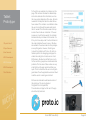
We also have a web based interactive version of
our tablet app. This can be found at:
http://platzh1rsch.ch/ipole2015/
Page 5
We all met for the first time at the physical
kickoff and began to plan out our project. This
section of the document looks at the
decisions we have made as a team and how
we will work together to tackle this project.
iPole 2014 Team Mcfly
Page 6
Initial
Teamwork
1.Physical Kickoff
2.Project Research
The first thing that we
did as a team was to introduce ourselves and
talk about our specialties. We were all aware
of the face we are all
from different backgrounds, on different
courses, and also from
different countries. Because of this we knew
there would be a wide
variety of not only skill
sets but also design
principles.
3.User Research
4.2016 Development
5.2016 Prototype
6.2024 Development
7.Final Reflection
We decided to do this
activity not only verbally, but also in a more
fun way. We each took
a piece of card and
wrote down our skills.
This was the easiest
way to get a quick
overview of what we all
did and therefore who
would be best suited
to what jobs during the
project.
To the right is the
outcome of this activity, we also have also
displayed our skill sets
in a table for better
visualisation.
iPole 2014 Team Mcfly
Page 7
Initial
Teamwork
Our next exercise was to figure out as a team what
our project time line should look like. This too a lot
of time, as we had to figure out what jobs had to be
done at what time. This was to make sure we did not
fall behind schedule at any point and to make sure
we had an overview of what had to be done. We
carried out this task by making a large poster and
attaching pieces of card to it with the tasks on. We
have split up the time line into important sections,
marking when the virtual reviews are and what we
have to do in the meantime to stay on track.
We have also made a digital copy of this time line
for us all to refer to on a regular basis to keep everything running smoothly. This also helped us to
determine what had to be completed and what we
would present at each peer review.
iPole 2014 Team Mcfly
Page 8
Team
Contact
1.Physical Kickoff
2.Project Research
3.User Research
4.2016 Development
5.2016 Prototype
6.2024 Development
We spent a lot of time figuring out what would be
the best time for us all to hold a video chat. This
was an important decision because we all had to
be available to talk every week. This was probably
the first problem we had encountered as a team,
as we are all from different timezones and all have
individual commitments that clashed. However we
all came up with a plan to meet every Thursday
evening at 8pm CET, this was the only time we are
all available. We also took this opportunity to note
down some general rules for the video calls:
Video conference rules
•Democracy for decision making.
•Don’t discuss things for too long. Céline is the
moderator and will move the conversation along if
a discussion goes on for too long. If Céline is away,
Chris is her proxy.
•Only one person talks at a time.
•We use hand signs (e.g. for “like it”, “don’t like it”,
“move on”, etc.)
•Be ready 5-10 minutes before the call.
•Tell the others if you can’t make it.
We decided to use Skype to make our video calls,
as this seemed to be the easiest option for us all.
As a team we also took this opportunity to discuss
how we would save and share our work. We came
to the decision to use a number of programs together to communicate and share our work.
We are primarily using Google Drive to store and
upload our work to. This is a great option because
it allows us all to edit the same document in real
time, so we can discuss things and change them
accordingly. We will also keep “meeting minutes”
of each video call, documenting what was discussed and the tasks that have to be carried out
for the following week.
7.Final Reflection
iPole 2014 Team Mcfly
Page 9
Team
Contact
1.Physical Kickoff
2.Project Research
3.User Research
4.2016 Development
5.2016 Prototype
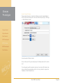
We are also using Trello as a form of weekly planning. Each time there is a team meeting we delegate tasks and these are put on Trello for everyone
to see. This program also lets you see what tasks
others are currently working on and what has been
completed.
6.2024 Development
7.Final Reflection
Finally we are also using Slack to tie everything
together. Slack allows us all to communicate as
a team in the same place. It organizes everything
into different sections so two people can converse
about UX while other speak separately about the
coding. This is a much neater and easier way of
working. Slack also allows Google drive integration, so we can upload and view all of our Google
documents in this program, again making life much
easier and more organised.
iPole 2014 Team Mcfly
Page 10
Visit to
Alstom
We also went on a field trip to learn more about
the company Alstom. We all took this opportunity
to take personal notes about what they expect and
the methods they use. Here are some of the notes
that we took:
Process
Permit to work
1.Physical Kickoff
2.Project Research
3.User Research
4.2016 Development
5.2016 Prototype
6.2024 Development
7.Final Reflection
At Alstom, safety is paramount. That is why for potentially dangerous jobs, they work with so-called
“Permits to work”. With these permits, they determine the risks for a certain assignment. Alstom
wants us to include this “Permit to work” process
in our prototype.
There are two types of “Permits to work”:
•General Safety Risk Assessment: This is for the
safety of the people
•System Safety Risk Assessment: This is for
assessing the machine
Lock-out and tag-out system
What does Alstom want to achieve?
•They want to replace paper (e.g. the permits and
manuals/instructions are still on paper)
•They want to speed up the work (e.g. by using
hands-free devices such as Google Glass)
•They want to be able to automatically look up
parts (e.g. the smart glasses would automatically recognize the relevant part and display the information for it).
•They want to be able to take pictures and integrate them into the reports.
•They want to be able to multi task (e.g. take a
measurement while dictating a report)
•They also consider using AR for training people
Furthermore, they work with the “Lock-out and tagout system”. With this system, they can make sure
that absolutely nobody will be able to use a part of
a system that is under maintenance (and therefore
potentially dangerous).
They lock the relevant part of the system and the
key to this lock is locked away with the permit to
work. Only the operator has the key to the box that
contains the key and the permit and he will only
open the box once the system has been properly
repaired.
In addition to locking the system, they also put a
tag on it (e.g. “Under maintenance - Do not operate!”).
•They would love a function that allows them to
share information (e.g. “I tried with 50t and with 100t - better go for 120t straight away!”) - This
would help them to save time
iPole 2014 Team Mcfly
Page 11
•They are also interesting in analysing the data.
(e.g. if they find out that a certain part needs to be replaced frequently, they can look into how they
could improve that specific part)
In general, it’s all about speeding up processes
and being able to work more efficiently. In short:
They want to save time and money (and paper).
Replacing vs. repairing
Visit to
Alstom
Replacing a part can be much cheaper than replacing it, because it is much faster. Alstom pays
up to 100.000 Euros a day if the plant has to be
taken off the grid.
Different types of inspections
At Alstom, there are different types of inspections:
5.2016 Prototype
6.2024 Development
7.Final Reflection
Language
For many technicians, English is not their first language. This is where visuals can help.
EHS
Knowledge & experience
2.Project Research
4.2016 Development
Data sheet findings are not (yet) centralised (i.e.
they cannot be analysed at the moment).
Environmental Health and Safety is an issue (e.g.
will people have headaches from wearing the
glasses all the time? Will they have deformed ears
because the glasses are so heavy?
1.Physical Kickoff
3.User Research
Data centralisation
Cranes
Cranes are mostly remote-controlled, i.e. the
crane driver can be standing next to the technician.
WiFi
Offices have WiFi; around the machines, WiFi is
not often available
There are many unexpected cases. If something
unexpected happens, they call the designer/engineer or the Plant Support Center who then helps
them. They send e-mails/pictures to communicate
the problem. They usually need to go back the
office to send the picture.
It would be cool if the designer at the other end of
the line could be talking to the engineer directly,
i.e. while he is still standing next to the machine so
they can tell him to move around the machine so
they can see it from the angle they need.
iPole 2014 Team Mcfly
Loss of knowledge and experience is a big problem for Alstom. Before, people worked for the
same company for 30 years, now they change
after 5 years. Also, the new technologies makes
people more lazy (they no longer have to learn
everything, because the information is available
and there when they need it).
Knowledge can be stored in a manual, experience
cannot.
Processes
Processes are important in a company that big.
But sometimes it would also be nice to have some
more freedom (e.g. not everyone approaches the
same task the same way).
Velocity
Finding the problem fast is important. If it takes
too long, the customer loses patience and Alstom
loses money (100,000 Euros/day).
Page 12
Use case for Google Glass
Visit to
Alstom
They have tried Google Glass. The use case is
as follows: The on-site technician wears Google
Glass and uses this device to communicate with
the Plant Support Center in Switzerland. The engineer in the Plant Support Center then helps the
on-site technician to find/solve the problem.
Predictive maintenance
1.Physical Kickoff
2.Project Research
3.User Research
4.2016 Development
5.2016 Prototype
6.2024 Development
7.Final Reflection
Alstom is looking into predictive maintenance. For
that, they use a system called CMMS (Computer-Managed Maintenance System). The reporting
goes into the CMMS. But: The CMMS is only as
good as the information that it is being fed.
For big contracts, Alstom installs a system on-site
(they can access the systems from Switzerland).
Real-time monitoring
They use real-time monitoring on site already. So
if for example there is a lot of vibration, the system
issues a warning and if it is not fixed in time, it will
automatically shut down.
Acoustic monitoring
Alstom works with ETH on acoustic monitoring. For
that, they measure the acoustics. They then compare the sound from day 1 with the sounds from
day 2. If it sounds very different, they know that
something is wrong. They want to use that acoustic monitoring for the steam valve we work on
These are all important points that we will have
to take note of when designing our interface for
Alstom.
iPole 2014 Team Mcfly
Page 13
Each team member took on a research topic
to look at. We all then presented our findings
in the form of a short presentation to the other
members. The following pages include the
research that was undertaken.
iPole 2014 Team Mcfly
Page 14
User
Manuals
Observations - what manuals
are like now
The manual must be structured in a way that
makes sense. There are different ways to do this,
for example:
A picture says more than 1000 words
Pictures/screenshot help a lot. They provide context. However, it is also a lot of work to always get
the latest screenshot’s/graphics, especially if the
manual is available in various languages.
•The manual describes the most important workflows that the software can cover. It then puts the focus on the workflow and guides the user through
it. The aim of these manuals is to show the user how something works, so he can then do it himself
afterwards.
Language
1.Physical Kickoff
2.Project Research
3.User Research
4.2016 Development
5.2016 Prototype
6.2024 Development
7.Final Reflection
The manual must be appropriate for the audience.
Example:
“In patients with severe COPD receiving inhaled
glucocorticoids and two classes of long-acting bronchodilators, glucocorticoid withdrawal was
non-inferior to continuation with respect to exacerbations but was associated with a slight worsening in lung function and symptoms.”A medical
doctor might understand this without any problems, but for the average person, this is not clear.
It is very similar with manuals: A very technical
description might be fine for someone who has
been with the company for 10 years or so, but a
newbie might have problems understanding it all.
•The manual describes all the functions of the
interface, starting on the left then going to the right
(see example below). These manuals are used
more for reference.
Clear sentences
Often, the language used is not clear. For example, many sentences are written in the passive,
which leads to problems. One example: “The stem
is then inserted into the valve” - Problem: Does it
happen automatically or does it mean that I have
to insert the stem into the valve?
iPole 2014 Team Mcfly
Page 15
Finding what you are looking for
User
Manuals
In paper manuals, it can be hard to find the information you are looking for. You either rely on
the Table of Contents or you browse through the
manual, hoping you will find whatever you are
looking for.
Digital manuals have the advantage that you can
search for a certain term in them, so this is already
a big step forward.
Relevant for the project
1.Physical Kickoff
2.Project Research
3.User Research
4.2016 Development
5.2016 Prototype
6.2024 Development
7.Final Reflection
Provide the right information for the right user at
the right time.
During the kick-off “the right information at the
right time” was a big topic. I also think that this
is the way to go: the required information should
be prompted when I need it; I should not have to
search for it.
“The right information” is a vague term though. I
think “the right information” is not the same for everyone. In a given situation, someone like Walter
Umbricht, who has been working for the company
for 30 years, will not need the same information as
someone who has just finished their apprenticeship. That is why I have added “for the right user”
to the above statement.
Amount of information
The amount of information should be just right not too little, but not too much either. Just give me
what I need to solve the task at hand. Don’t give
me any background information on the machine
I’m working at if that doesn’t help me with the task.
iPole 2014 Team Mcfly
Intelligent manuals
As outlined above, digital manuals have already
made things easier.
In a next step, user manuals should be more
intelligent, more proactive. Until now, the user has
to look for something, and he also has to know
what the thing is called that he is looking for (if I
looked at that steam valve, I wouldn’t even know
what to search for, because I’d have no idea what
the different parts were called). Intelligent manuals should do this work for him. That means they
should provide the necessary information automatically.
Distraction
What we should also look out for is that the manual itself does not distract the technician from the
task at hand. It should be there, but it should be
unobtrusive.
Global workforce
We should bear in mind that Alstom has power
plants all over the world. Therefore, there will be
lots of people whose mother tongue is not the one
that is spoken on site.
Maybe the manual will be available in all kinds of
languages, maybe it will only be in English because it’s company language - we could maybe
contact Alstom to find out more about that.
In any case, the language used in the manual
should be simple and clear (no complicated sentences, etc.). Pictures/videos can also help bridging the language gap.
Page 16
Alstom
Workflow
1.Physical Kickoff
2.Project Research
3.User Research
4.2016 Development
5.2016 Prototype
6.2024 Development
7.Final Reflection
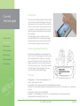
We wanted to understand the process fully that
Alstom wants us to use technology for. We looked
deeper into what they actually do and the various
steps that are taken during the maintenance of a
steam valve.
2. Work preparation
•Carry out the work
Execute the work with general safety implemented
•Clearance on completion
The 3 main sections are:
System normalized & equipment returned to service
•Permit to work process
•Work preparation, disassembly / reassembly
instruction / inspection
•Reporting
3. Reporting
1. Permit to work process
•Measurements need to be logged
•Operating data for the part (valve, critical parts)
•Pictures are required to show the condition
•Work order
Define the work scope & methods
•General Safety Risk Assessment (based on work
scope / methods)
Identify risk & define the control measure
•Application to work for system safety risk consideration
•System Safety Risk Assessment (SSRA)
•Assessments of the parts for further use
•What needs to be replaced based on the condition & what are the replacement parts
(identification)
•Are there things that need to be repaired?
•Test results
Identify the system hazards & define the control
measures
•Safety at work
•Isolate System & issue the safety document
•New ideas to make work easier / safer
(based on SSRA result)
System hazards controlled & equipment released
for work.
iPole 2014 Team Mcfly
Page 17
Smart Glasses
Design
Principles
1.Physical Kickoff
2.Project Research
3.User Research
4.2016 Development
5.2016 Prototype
6.2024 Development
7.Final Reflection
We also researched into what we should produce, what our smart glasses application would
incorporate and also how it should ultimately be
designed. We came up with the following points to
define our goal:
Less is More
This is an common seen design principle.
Its easy to add information, but much harder to
take them away. Because it requires a true understanding of the user.
It is more important to create a minimalist and
usable interface than a flashy
Iron Man-like interface.
Keep it simple: don’t confuse the user with too
many functions.
Focus on the Glasses
“People will use smart glasses for a reason. We
needed to design a completely hands-free user
experience. After all, if you need to swipe and tap
with your fingers to interact with your glasses, you
might as well use a smart phone or a tablet.”
Design for different environments
Transparent displays have a special design challenge, you don’t know what is going to be behind
them. Some users will be in a sun-filled workplace
while others will be in a dark environment.
So the user interface need always a high contrast
between the environment.
People don’t like change
If we want to create a usable app, we need to
begin to analyse the way people already act and
use other devices. If the design is common with
something the user already know, it could help
them to understand the application.
The two design layers
On the one hand we have the more fixed-layer(2D-head-up display), which is more readable
for information. (Straight lines, high contrast to the
real world).
On the other hand we have the layer that is more
connected to the real world(3D-real-world), which
could be more useful to navigate and interact with
the application. (Rounded look)
iPole 2014 Team Mcfly
Sources:
http://www.apx-labs.com/design-principles-for-smart-glasses/
Page 18
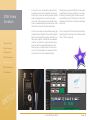
Current
Technologies
We looked at what technology was available now
for us to work with, we know that we have top create a prototype for 2016 so we looked into what
the cutting edge of technology has to offer and
how we can implement these technologies into
our design.
Epson Glasses
1.Physical Kickoff
2.Project Research
3.User Research
4.2016 Development
5.2016 Prototype
6.2024 Development
7.Final Reflection
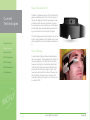
We took a look at the epson glasses website —
(http://www.epson.com/cgi-bin/Store/jsp/Landing/
moverio-bt-200-smart-glasses.do) to have a look
into what they are actually capable of. We have to
know what these glasses can do and the technology that will work with them before we can begin
to design for them.
•We found that we can use a bluetooth mouse
• The glasses use and SD card 64 GB in NTFS
format.
• And also that BT-200 can handle 2D and 3D
graphics
We also looked at a few articles relating to these
technologies:
•http://www.slashgear.com/forget-glass-insideepsons-scheme-to-be-the-de-facto-smart-glassesfirm-08315882/
• http://www.slashgear.com/epson-moverio-bt200-review-smashing-glass-23334807/
We have all tested the glasses and came to some
of the following conclusions:
•They are low resolution, which is not preferable
and keyboard with Epson glasses, this could be a
possible alternative instead of the small touch pad
that is currently attached to the device.
• If you watch a video for a long time the touch
pad will warm up and you can`t use it, this is not
good from a usability point of view, however if we
use a mouse, this should be ok.
• Epson glasses is fine for augmented reality,
however not so much for virtual reality. This is
because there is only a small portion of the glasses that is used to show information. There is only a
small square in the centre of the users vision that
is a straight mirror of the users computer screen
in real time. This is not a fully immerse experience
and the location of the information can sometimes
obstruct the users field of view.
• We discovered that it is possible to use an
accelerometer (+90° / - 90°) with the glasses. This
could be used for navigation issues.
with todays technology available.
•The glasses are Clunky and quite heavy (you
cannot wear them all day) Ideally, they would just
be safety glasses with additional functionalities.
•The battery does not last long.
•Control using the manual remote is awkward.
•Wearing the glasses for a long time might make
you feel dizzy.
•The camera is currently located at the bottom
left. Moving the camera to the middle would have
the advantage that the recorded image would not
be offset so much from the user’s actual view. Another thing that would help, is if the app would not
show the image provided by the camera, but only
the AR object, but then try to place it correctly.
Instead of the camera image, there could be just
a transparent / black background and the camera image would be processed in a background
process.
•They don’t seem to support regular headphones.
iPole 2014 Team Mcfly
Page 19
Meta 1 Developer Kit
Current
Technologies
1.Physical Kickoff
2.Project Research
3.User Research
4.2016 Development
5.2016 Prototype
6.2024 Development
7.Final Reflection
The Meta 1 glasses are some of the most exciting
glasses in development at the moment, they are
the only AR glasses that allow two people to view
and interact with the same information in space.
For example one user could pick up an AR object
and the other user would be able to see them doing so and track the movement of the object.
This technology would be interesting to use for our
brief if it was possible, as the multiple users could
share and edit the same information simultaneously.
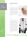
Vuzix Glasses
A second pair of glasses that we looked at were
the Vuzix eyewear. These glasses seem similar to
the epson glasses in the way that they function,
however one thing that is interesting about them
is the way they have been implemented into the
working environment (see image to right). They
have been attached to the helmet of the user and
do not obstruct the users view in any way, this
could be something to look at for our future vision
or even for 2016.
iPole 2014 Team Mcfly
Page 20
Navigation/Control Methods
Current
Technologies
1.Physical Kickoff
2.Project Research
Leap Motion
We also looked at the Leap Motion for the possibility of gesture-based controls for our smart glasses. Leap Motion is great for this. It con recognise
a number of gestures to allow you to control your
computer. The Leap Motion can identify where
the user is pointing on the screen to make selections and also can measure the angles between
fingers, this allows the user to create “hot keys”
from their hands to quickly carry out tasks by just
making a sign.
3.User Research
4.2016 Development
5.2016 Prototype
6.2024 Development
7.Final Reflection
Control VR
“Control VR was designed to be versatile and
used with a variety of operating systems and
platforms. The development kit comes with more
than 10 free applications for the PC as well as an
open source SDK for developers to create the
applications of the future with Oculus VR, Google Glass, Unity, Unreal, Autodesk software and
even the Parrot AR Drone!”. This technology uses
gesture based controls, without the use of cameras, which means that it will be less likely for the
camera to pick up a mistake. However the user
will be wearing the gloves whilst working and so
it still may trigger some things and also if the user
is wearing gloves whilst working, this could be a
safety problem!
iPole 2014 Team Mcfly
Page 21
Current
Technologies
1.Physical Kickoff
2.Project Research
3.User Research
4.2016 Development
5.2016 Prototype
6.2024 Development
7.Final Reflection
Ultrasound
There are also existing examples of ultrasound being used to interact with technologies. This again
uses gestures and so it would be much easier for
the user to interact with, however instead of a video camera it is sound, meaning that the user can
make the gestures anywhere and they would still
be recognised.
This technology is great, however it has been
mentioned that the user may accidentally trigger
something with hand movements because of the
work they will be doing on the steam turbine.
Samsung keyboard interface
We looked at possibilities for documenting information. One of the technologies that came up was
this virtual keyboard from Samsung. This allows
the user to bind certain letters to sections of their
fingers and allows the user to type by looking at
the letters you wish to use. This could be useful for
our brief, however it also depends on how advanced and how fast this technology is.
Sources:
•Meta glasses - https://www.spaceglasses.com/
•Vuzix - http://www.vuzix.com/
•Leap Motion - https://apps.leapmotion.com/apps/bettertouchtool/osx
•Control VR - https://www.kickstarter.com/projects/controlvr/control-vr-motion-capture-for-vr-animationand-mor
•Ultrasound - http://vimeo.com/108101901
•Keyboard - http://24gadget.ru/1161057217-virtualnaya-klaviatura-osnovannaya-na-tehnologii-dopolnennoy-realnosti-3-foto.html (ru)
iPole 2014 Team Mcfly
Page 22
Future
Technologies
We live in a world today where it is impossible to
predict where technology is going, we no longer
an tell what will be possible in 20 years time, as
technology is moving so quickly, the possibilities
are huge. Years ago, researchers believed we
would have flying cars by the year 2,000, yet we
may never actually reach this goal.
Although we can not predict these new technologies and say for sure, we can have an educated
guess as to where the technology may head.
1.Physical Kickoff
Navigation/Control Methods
2.Project Research
Navigation and the controlling of information is an
essential part of any system, and in the case of a
digital user manual it is even more so, as the user
has to be able to control the information on screen
and navigate through instructions. In the present
day, there is some innovative control methods that
work to some extent. Voice recognition technology already is pretty advanced, however it could
be better. Also there is gesture based camera
controls, so the camera could potentially pick up
the users hand movements to navigate. However
in the future, we could have even more amazing
ways to navigate.
3.User Research
4.2016 Development
5.2016 Prototype
6.2024 Development
7.Final Reflection
Brainwave
Assessment
Identifies
Imbalances
Optimizes the
waves for that
person
Non-Evasive
Sensors Placed
on the Head
iPole 2014 Team Mcfly
Brain-wave Technology
One idea concerning this is the use of brain-wave
technology, this is currently being developed and
it currently allows the user to do small things, such
as turn a switch on and off by thinking certain
thoughts. But in the future this could be expanded
into a fully functional way of controlling an interface, where the user can simply think what they
want to do and the glasses would display the
correct information. This would allow the user to
navigate through a user manual and possibly even
dictate text through though, which could save a lot
of time and errors, as the noisy environment limits
the use of todays voice recognition technology.
Software
Translates Data
into Sound
Brain
Recognises
Imbalances &
Recalibrates
Brainwaves
balanced and
transfered into
data
Page 23
Smart Technology
Future
Technologies
1.Physical Kickoff
2.Project Research
3.User Research
A second possibility for future technology could
be a “smart system”. This is again currently being
tested and developed by major technology companies in the context of smart homes. The idea
being that you come home and your home knows
everything you want. What TV channel you want
on, what meal you want for tea. It will even know
how you are feeling and will change music and
decor in the house to cheer you up. This could be
implemented into a smart user manual in some
smart glasses. The technology could possibly be
so advanced that it knows what parts you are unsure of because of how others have reacted. It will
adjust the level of help automatically and make
suggestions for parts you may be unsure of.
4.2016 Development
5.2016 Prototype
6.2024 Development
7.Final Reflection
Human-Computer Integration
Merging humans with computers is something
that is not currently any where near completion,
however it may be available in the year 2024.
This would involve there being some sort of touch
interface on the users arm, this may be projected
or built in. In the context of our project, this could
be used as a second screen for the user, allowing
them to type, take notes and view extra information at a quick glance. If developed further, this
technology could even replace smart glasses
altogether. Also this technology could be possibly
integrated with the previous I have mentioned to
create huge possibilities.
iPole 2014 Team Mcfly
Page 24
Advanced Eye Tracking
Future
Technologies
1.Physical Kickoff
Eye tracking is currently a technology that is used
a lot. It has even been integrated into some mobile
phones to allow the user to scroll through images
and text. However, this technology has not yet
been developed and used for wearable technology such as smart glasses. This technology could
be very helpful for our brief, as it would remove
the need for voice control. Voice control could be
a problem for this brief because of the noisy environment that workers will be in.
2.Project Research
3.User Research
Other
4.2016 Development
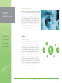
Internet of Things
5.2016 Prototype
6.2024 Development
7.Final Reflection
The internet of things is the theory that in the
future, everything that we own will be digitally
connected in some way, similarly to the previous mention of “Smart Technologies”, all of the
products will know the users feelings and movements. The Internet of things however, refers to
the communication between the digital products.
This will be especially helpful when it comes to the
documentation and recording of information that
Alstom expect us to achieve. Once an image is
taken it will automatically be sent and inserted into
a document, the user will then be able to speak a
sentence and this too will be added in as text next
to the image or wherever necessary.
iPole 2014 Team Mcfly
Page 25
Android &
AR
Frameworks
1.Physical Kickoff
2.Project Research
3.User Research
4.2016 Development
To find out what would be the best program to use
we also carried out some background research on
the different typed of AR frameworks and looked
into their possibilities.
Android
Android is a linux-based operating system for mobile devices created by Google. The first Android
devices entered the market in October 2008.
Since then the system gained a lot of popularity.
More than a billion phones and tablets around the
world are running on Android, which makes it the
most popular mobile operating system.
The latest software version is Android 5.0 (Lollipop), which brings a new design, better synchronisation across devices, multiuser support as well
as integrated support for watches, TVs and cars.
5.2016 Prototype
6.2024 Development
7.Final Reflection
•Android Wear
AR Frameworks
The idea of augmented reality already appeared
in 1901 in “The master key”, a book by the well
known author L. Frank Baum who also wrote “The
wizard of Oz”. Since then, this topic was discussed by lots of different people, but it was only
in the late 90ies when there were the first attempts
to create applications and frameworks for this
matter. We will try to evaluate the existing frameworks as well as their pro and contras.
•Metaio
Metaio is a privately held Augmented Reality
company that develops software technology and
provides augmented reality solutions. Headquartered in Munich, Germany, with subsidiaries in
San Francisco, California, New York City, New
York and Dallas, Texas, metaio provides a software development kit (SDK) for programming PC,
web, mobile and custom offline augmented reality
applications. Additionally, Metaio is the creator
of Junaio, a free mobile AR browser available for
Android and iOS devices.
In March 2014, Google announced Android
Wear, which is a version of Android designed for
smartwatches and other wearables. Android wear
devices can be paired with your Android Smartphone via an Android Wear app over bluetooth.
To install the Android Wear app, your device
has to run at least Android 4.3. Since Apple just
announced their Apple Watch as well, there will
definitely be a lot of interesting stuff happening in
this domain.
iPole 2014 Team Mcfly
Page 26
Android &
AR
Frameworks
1.Physical Kickoff
2.Project Research
3.User Research
4.2016 Development
5.2016 Prototype
6.2024 Development
•Metaio Creator
Metaio creator is a tool to easily create simple
tracking and AR combinations. The tool is free of
charge with some limitations (only 2 trackables
and 2 3D models). It is possible to upload the socalled “channels” to the Metaio Cloud for use in
the Junaio app. One can also export the created
channel to Unity or Eclipse for further modification.
More info: http://www.metaio.com/creator/
•AREL (Augmented Reality Experience
Language)
Metaio has its own programming language to use
for their SDK, which allows you to write apps in
Javascript, HTML and CSS. This could be really
interesting in regards to designing the glasses
interface.
https://dev.metaio.com/arel/overview/
•Metaio SDK
The metaio Software Development Kit (SDK) is the
framework that is also used to power the metaio
creator. It allows programmers to easily use metais object and image recognition algorithms, as
well as their 3D API.
The SDK is available for every well known mobile
operating system.
7.Final Reflection
•Junaio Browser
Some numbers from the Metaio website.
It’s possible to create channels for the very popular AR browser “junaio browser”.
•Wikitude
The austrian company Wikitude was one of the
first to develop a AR browser and publish it free
of charge in 2008. Their app, the wiktude world
browser, uses the location data of the device to
display interesting information to the users based
on their location.
iPole 2014 Team Mcfly
Page 27
Android &
AR
Frameworks
•Wikitude Studio
Sources
Like Metaio, Wikitude is also providing a very easy
to use tool to quickly create AR content that can
then be added to the wikitude world browser database or can be used for individual apps.
http://developer.android.com/index.html
http://developer.android.com/training/index.html
http://socialcompare.com/en/comparison/augmented-reality-sdks
http://www.t-immersion.com/
http://www.xloudia.com/
http://www.metaio.com/
http://www.wikitude.com/
http://www.wikitude.com/products/eyewear/epson-augmented-reality-sdk/
http://www.epson.com/cgi-bin/Store/jsp/Landing/
moverio-bt-200-smart-glasses.do
•Wikitude SDK
1.Physical Kickoff
2.Project Research
3.User Research
Wikitude is also offering an SDK to create Augmented reality apps. Other than metaio, they do
not only provide tracking based on images, but
also on location. Their SDK is available for many
development environments like Android, iOs,
Smart Glasses, Phonegap, Titanium or Xamarin.
4.2016 Development
Conclusion
5.2016 Prototype
I think the best solution to use would be the Metaio
SDK. Most of the other teams will also be using
this technology and therefore it will be easier to
exchange knowledge and solve eventual problems. We could even do simple prototypes using
Metaio creator without writing one line of code.
Also with the possibilities of AREL, everyone that
knows Javascript, Html, Css and a bit of XML
should be able to contribute to the development
and design of the prototype.
6.2024 Development
7.Final Reflection
iPole 2014 Team Mcfly
Page 28
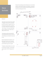
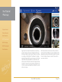
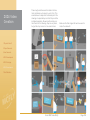
Our idea after Review 1 was to extend our lego
prototype by 3D object recognition and exchange
the model with the steam turbine. There are two
different approaches for this: one is using the 3D
model itself as a trackable, the other one is to
create a 3D map of the physical object (the steam
valve model we received on the kickoff meeting)
with a smartphone using the Metaio toolkit.
3D Object
Scanning
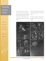
3D object scanning using 3D model
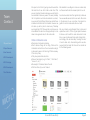
The first way to do 3D object scanning that we
tried, is to provide a 3D model as a trackable.
After loading the steam valve model as a trackable, we can adjust the detail level we want to
use.
1.Physical Kickoff
2.Project Research
3.User Research
Left top: The steam valve model in the 3D model
tracking assistant.
4.2016 Development
5.2016 Prototype
Then we need to choose the line detail level:
6.2024 Development
Left bottom: Visualisation of the line reduction in
the 3D model tracking assistant.
7.Final Reflection
iPole 2014 Team Mcfly
Page 29
3D Object
Scanning
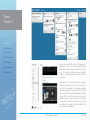
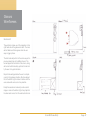
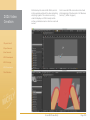
Finally, we had to define the tracking scenario, as
seen from the screen shot below:
1.Physical Kickoff
2.Project Research
3.User Research
4.2016 Development
5.2016 Prototype
6.2024 Development
7.Final Reflection
The dialog to choose a tracking scenario
After defining the trackable, we add the 3D object
to display - again the steam valve model - and
export it as a channel to metaio cloud. The result
is not overwhelming:
Screenshots of end result in Junaio using 3D model tracking
iPole 2014 Team Mcfly
Page 30
Conclusion
3D Object
Scanning
1.Physical Kickoff
2.Project Research
In conclusion to the 3D object scanning in Metaio,
3D object scanning using a 3D model looks promising while setting it up in Metaio creator, because
you can overlay the trackable directly and 1:1 with
the 3D model. But when it comes to real life application, you can see that it is not that easy. The
3D model gets placed just anywhere around the
object, but not nearly overlays it.
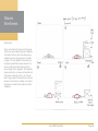
3D object scanning using 3D map
Another possibility is to create a 3D map of the
steam turbine model, using the Metaio Toolkit app,
and use that as a trackable.
3.User Research
4.2016 Development
5.2016 Prototype
6.2024 Development
7.Final Reflection
Generating 3D map using the Metaio Toolkit app
for Android.
iPole 2014 Team Mcfly
Page 31
3D Object
Scanning
We can then export the created map from the app
and import it into the Metaio Creator as a target.
1.Physical Kickoff
2.Project Research
3.User Research
Creating a trackable in Metaio Creator
4.2016 Development
As a next step, we import the steam turbine model
and place it in the 3D map. This is quite tricky, as
we don’t see the captured images, only the marker points of it:
5.2016 Prototype
6.2024 Development
7.Final Reflection
This is how the 3D map is displayed in Metaio creator, one can also see the
3D model that would be shown when the 3D map is found by the camera (in
grey)
iPole 2014 Team Mcfly
Page 32
3D Object
Scanning
We can then export this as a channel to the metaio
cloud, and open it with the Junaio app. However
the results we get are not very good:
1.Physical Kickoff
2.Project Research
3.User Research
4.2016 Development
5.2016 Prototype
6.2024 Development
7.Final Reflection
Screenshots of the end result with 3D map based
tracking
The 3D model is placed differently depending on
the angle you look at the model. Also it flickers
quite a lot, as if it may lose track of the tracker.
Conclusion
Although 3D object recognition with SLAM sounds
like fun, it really is not. You can not yet choose
what exactly in the view of the camera the object
is that you want to map, so it just scans everything
in the viewport. This means you would need a
completely neutral background for the scanning.
Also the display of the 3D model based on the 3D
map is very unstable.
iPole 2014 Team Mcfly
Page 33
Future Vision
Videos
1.Physical Kickoff
We have also looked into the videos that have
been produced by large corporations for their
future visions. These videos have been produced
for a company 2020 vision. They have been completed to a high standard including mock-ups and
graphics to illustrate what the company aims to
achieve by the year 202. Looking at these videos will come in useful because it shows us their
prediction of future technologies and how they
expect to use them. This is similar to what we will
be doing for our future concept video.
2.Project Research
3.User Research
4.2016 Development
5.2016 Prototype
6.2024 Development
7.Final Reflection
Coca-cola Video
Available here: http://www.coca-colacompany.
com/investors/videos-from-cage-presentation
Microsoft Video
Available here: http://osxdaily.com/2011/10/27/
microsofts-vision-of-the-future-everything-is-touch-video/
These videos provide a clear vision and will
inspire us to create something similar. Both to
advertise out 2016 product and more importantly
for the future.
iPole 2014 Team Mcfly
Page 34
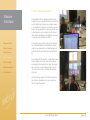
The next step was to undertake some user research. We began this by creating some user pesonas to give us all an overview of the people who
we would be designing for. We need to know what
product will work for them and how skilled they are
with technology.
We have also created some customer journey
maps for both the current workers of Alstom and
also for the predicted future users of our product.
iPole 2014 Team Mcfly
Page 35
Mario
Kleiner
“I’m confident, but
nobody is perfect.”
Gender:
•Male
Age:
•22yrs
Job
Occupation:
•Trainee
Nationality:
•Swiss
Bio:
Mario is a recent graduate at Alstom. He has
been trained by the company over the past few
years and so is fairly confident with the task at
hand. He has been working in the training facility for a number of years now alongside other
students and likes the team aspect of working in
Alstom. For all he is confident, he does not have
a lot of experience when it comes to steam turbines, he has taken apart many during training
exercises but is a little apprehensive with doing
the job for real.
User Needs:
Mario needs a system that will prompt him at the
correct time and give him the information that he
wants, exactly when he needs it. He also would
like a way to be able to take notes quicker, as he
hates having to write up reports and send emails
every time!
Technology Skills
Task Confidence
Level of Expertise
Mario’s life revolves around technology, his phone
is constantly getting notifications and he has no
problems with learning new things concerning
technology.
iPole 2014 Team Mcfly
Page 36
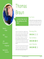
Thomas
Braun
“I just don’t have time for
documenting every little
detail”
Gender:
•Male
Age:
•41yrs
Job
Occupation:
•Engineer
Nationality:
•German
Bio:
Thomas is an engineer that is regularly hired by
Alstom to come in and service the steam turbines.
He lives just a few hours away in Germany but
has to travel regularly in order to complete the
jobs he is given. At the age of 41, Thomas has
plenty of experience of steam turbine valves,
having serviced many during his career so far. He
knows that it can be a lengthly process, especially if everyone doesn’t work quickly and efficiently
together.
Thomas is one of the older generation desperately trying to fit in with the “young ones” with technology. He owns an iPhone4 however struggles
when it comes to anything more complex.
iPole 2014 Team Mcfly
User Needs:
Thomas needs to have s system in place where
he can keep in contact easily with the other workers he is with. Also he wants to be able to make
sure everyone is safe on the job, as he tends to
take a paternalistic role during work activities.
Technology Skills
Task Confidence
Level of Expertise
Page 37
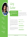
Jürg
Sutter
“I have no idea how to
work the gadgets these
days”
Gender:
•Male
Age:
•56yrs
Job
Occupation:
•Engineer
Bio:
Jürg is highly thought of by his team members
when it comes to work, he is a skilled specialist
in the field of turbines. He can be seen as a little
bit of a control freak and tends to boss people
about in the workplace. He doesn’t mean to but
he knows he is speaking from experience and it
will all be passed down to the people he is working with.
Jürg is a self confessed technophobe. He struggles to operate his TV never mind a fancy smart
phone. He likes to try new technologies but rarely
finds anything usable for him.
User Needs:
Jürg needs a simple to use interface that he can
easily understand and learn about from others.
He wants to be able to speak clearly to the others,
as at the moment he struggles to hear in the loud
environment.
Technology Skills
Task Confidence
Level of Expertise
Nationality:
•Swiss
iPole 2014 Team Mcfly
Page 38
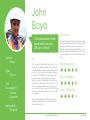
John
Boyd
“Communication is the
issue when you are
30ft up in the air”
Gender:
•Male
Age:
•33yrs
Job
Occupation:
•Crane
Operator
Nationality:
•English
Bio:
John is a laid back and calm crane driver, he is
regularly hired and dispatched by Alstom to aid
in the dismantling of steam turbines. Have a new
born child, John is used to multitasking, however
he does find this difficult in a noisy environment.
He and his team mates need to rely on hand
gestures and an old walkie-talkie to allow him to
operate the crane efficiently. He has to be in constant communication with those on the ground,
especially when moving large parts of the turbine,
as anyone could be seriously hurt, or a part could
be damaged.
User Needs:
John needs a system that will aid his team mates
on the ground, but allow them to have hands free
contact, and possibly even a way for them to
show him what is happening down there in more
detail. He thinks this would be a fantastic way to
work and will stop any minor mistakes before they
occur.
Technology Skills
Task Confidence
Level of Expertise
John loves technology, his father has worked in
a design company and so he has always been
around the latest tech.
iPole 2014 Team Mcfly
Page 39
Current Alstom
Workflow
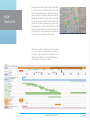
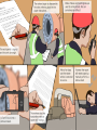
Below is a customer journey map for the current workers at Alstom. This
shows the different stages in the process of servicing a steam turbine valve
and the workers feelings towards each stage.
1.Physical Kickoff
2.Project Research
3.User Research
4.2016 Development
5.2016 Prototype
6.2024 Development
7.Final Reflection
As you can see from the diagram above, the
current Alstom process is lengthly, especially with
the need for documenting after the job has finished. This also extends the time period of the job
because the worker has to stay to complete the
documentation before sending it.
Furthermore, the documentation could be completed alongside the task. The worker could dictate the problems that arise and take images with
the camera glasses.
iPole 2014 Team Mcfly
This can be automatically compiled and inserted
into a document to save the need for lengthly documentation after the job has been finished!
Also the communication is something that could
be improved. Currently the worker has to put their
tools down and ring someone off-site for extra information, this could be improved by having built
in web chat with an external specialist.
Page 40
Proposed
Workflow
Below is a potential customer journey map for the Alstom workers using our
solution to the brief. This again outlines the various sections and how the
user feels at each stage.
1.Physical Kickoff
2.Project Research
3.User Research
Proposed Alstom
Workflow
4.2016 Development
5.2016 Prototype
6.2024 Development
7.Final Reflection
As you can see from the diagram above, the before stage of the cycle will stay mostly the same,
the user will still have to go through all of the relevant safety procedures before beginning the task
of servicing the steam valve.
Also there are the additions of easier contact with
team members and other staff. If there is a problem and the worker needs to be put in contact
with someone else, then this will be seamless and
easy, triggered with a voice command.
The during stage of the process has a few more
points, but this is mainly due to the integration of
reporting into the actual work process, this will
greatly reduce work hours, as the worker will be
able to do two tasks at once, without losing concentration on the job.
The use of instructions is also a great improvement, instead of following a paper guide or
remembering the instructions the worker will be
provided with step-by-step instructions to aid
them.
iPole 2014 Team Mcfly
Page 41
iPole 2014 Team Mcfly
Page 42
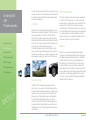
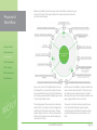
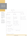
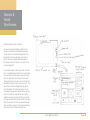
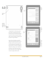
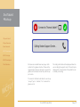
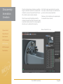
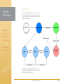
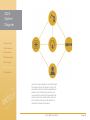
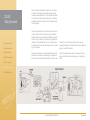
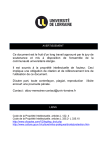
We have drawn up these two system diagrams for
2016 to give an overall idea of how the user will
connect with the glasses, the reporting system
and also with a secondary member of staff, stationed elsewhere to aid with any queries.
2016 System
Diagram
The Diagram to the left shows how everything
would link up if we were to only use a pair of
smart glasses for everything. The user would use
the glasses, which would be able to connect to
another member of staff and the company’s cloud,
and therefore the user would have access to the
reporting systems, which would enable them to
write reports.
1.Physical Kickoff
2.Project Research
3.User Research
4.2016 Development
5.2016 Prototype
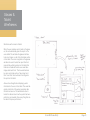
This second diagram is essentially the same but
with the addition of a tablet, everything would
connect together to create a user friendly system
that will work quickly and efficiently. We have decided to potentially add in a tablet into the system
because this would be the best way to solve the
problems that Alstom have set. We believe that
the glasses can be used to show helpful animations and images, whilst the tablet will come in
as a helpful second device that will display extra
information and allowing more efficient reporting
and communication for the user. Each user would
have a pair of glasses and a tablet to ensure that
each worker can access the information relevant
to them, when they need it most.
6.2024 Development
7.Final Reflection
iPole 2014 Team Mcfly
Page 43
Now that we have all of our research conducted and know where this project should lead,
we can now start the process of designing the
user interface and getting feedback from both
peers and users in order to make our project
a success.
iPole 2014 Team Mcfly
Page 44
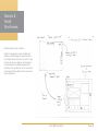
Glasses App
Architecture
To begin with, we
started looking at the
system architecture for
the glasses interface.
This would help us to
know what information
needed to be shown on
what pages.
Our interface will consist of 3 main pages
that will be easy to navigate and will all include
relevant information.
iPole 2014 Team Mcfly
Page 45
Glasses
Wireframes
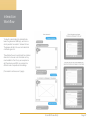
To begin with we wanted to get some initial ideas down, so a few initial wireframes were created. We then planned to give feedback on these designs
and produce more and more iterations until we were all happy with an outcome and we could progress from there.
Wireframe #1
This wireframe was the first idea for the navigation
of the glasses. We have kept these designs simple with 3 main sections in separate corners. This
is to keep them out of the users line of sight and
to not cause and distractions. Depending on what
“mode” the user is in, the relevant symbol will be
larger and a different colour to allow the user to
always know what is active.
The job mode (top right) will have the step title
and a small description underneath. This will also
include 3d images or animations of the step to aid
the user.
Report mode (bottom left) will enable the user to
take images and create a report in the glasses.
This will pop out at the side and allow the user to
input information through voice recognition.
The assistance mode will allow the user to send a
live video stream or images to an external helper
and receive help in the form of images and videos.
iPole 2014 Team Mcfly
Page 46
Glasses
Wireframes
Wireframe #2
This wireframe makes use of the navigation on the
right hand side of the glasses interface. The icons
will be hidden and then appear when the user
says a trigger phrase.
The Job mode will perform in the same way as the
previous design but with a different layout. The
text will appear at the bottom of the screen, along
with some health and safety symbols that will notify the user of any potential risks.
Report mode will again allow the user to compile
a report in the glasses interface. We have placed
this in the bottom right to make it interfere with the
users real world work as much as possible.
Finally the assistance mode will provide a small
image or video in the bottom fight of any help that
has been sent across from the external technician.
iPole 2014 Team Mcfly
Page 47
Glasses
Wireframes
Wireframe #3
This is our third idea for the layout of the glasses.
This time we have looked at having the navigation
at the bottom of the screen. These ideas are essentially the same as the previous but in a different layout. The main addition in this wireframe is
the Speech symbol that has been inserted. This
will be a small symbol that will glow when the
user is talking to their colleagues. This will greatly
improve interaction, as the user will be able to tell
if the device is listening to them or not. This will
work through a push to talk system where the user
will have to hold a button, probably on the side of
the glasses, to activate the microphone to talk to
colleagues.
iPole 2014 Team Mcfly
Page 48
Tablet App
Architecture
Because at this stage
we were thinking about
implementing a tablet
into our designs, we
started to look into a
possible system architecture for this. We
looked into what should
be on each page and
how these pages would
link together.
To the right is the system architecture that
we came up with:
iPole 2014 Team Mcfly
Page 49
Glasses &
Tablet
Wireframes
Wireframes with inclusion of tablet.
As we were looking at adding a tablet into our
solution, we drew out some initial wireframes to
look at what we could potentially display on the
tablet and how the two devices could work together. We used a slightly different design for
the glasses interface, however it is similar to the
previous design #2.
For the tablet interface on the job mode, there will
be a more detailed description of the task at hand,
this is so if the technician wants some extra help,
they can request this to be shown on the tablet.
This would be done through a voice command of
something along the lines of “show me more”. This
would then activate the tablet and bring up the
extra information. The tablet would also include
some helpful images and videos that the user can
look at to help them complete the task. Another
addition would be past report findings on the tablet. These would be the important points that have
been previously found, this could potentially help
solve a problem quickly if it has happened before,
without the need to contact someone else.
iPole 2014 Team Mcfly
Page 50
Glasses &
Tablet
Wireframes
Wireframes with inclusion of tablet.
When the user activates report mode on the glasses, this will automatically open the report on the
users tablet. This will allow the glasses interface
to be much clearer, as all of the information will be
on the tablet. The voice recognition on the glasses
will allow the user to hands free report their findings and they will be typed out on the tablet. We
have also considered how the user would take
images and insert them. This too would be done
by voice commands such as “take image” and
then “insert that” which will insert the image into
the report on the tablet.
Also we have thought about displaying useful
information to the user on the tablet. This would be
graphs and charts of the system operating data
since the last service. This will allow the user to
look at the data and see how the system has been
performing, and weather there is anything that can
be done to improve performance.
iPole 2014 Team Mcfly
Page 51
Glasses &
Tablet
Wireframes
Wireframes with inclusion of tablet.
Finally for the assistance mode, the tablet will
display any helpful images or videos that the external helper will send across to the user. The user
can then say “show on glasses” which will open
a small window on the glasses displaying this
information. This will allow the user to concentrate
on the job whilst being able to refer to some extra
help in the glasses.
iPole 2014 Team Mcfly
Page 52
Wireframe
Feedback
Wireframe feedback points.
1.Physical Kickoff
2.Project Research
3.User Research
4.2016 Development
5.2016 Prototype
6.2024 Development
7.Final Reflection
We all discussed the wireframe ides over Skype
and decided on the following points:
•Design #1 was most popular (with icons in the
corners). This was because the design was the
simplest to navigate and allowed the user to constantly see what “mode” they are in. We all especially liked the way in which the icons were larger
and in colour when in use.
•Have no text displayed on the glasses, only
icons. This is mainly because text is very hard to
read and understand when on the glasses, unless
it is against a high contrast background, and even
then this will take up more space on the glasses.
All of the text can be taken away and only imagery
used, which will save space. This can be solved
by voice instructions, so there will be previously
recorded instructions that will be played at the
start of every task. Everyone also liked the use of
the tablet to display information and the “show me
more” command that gives the user the option of
more information if they need it.
•Any images/videos displayed in the corners of
the glasses will be too small so we should keep
this on the tablet, maybe make the images on the
tablet expandable, so the user can click on them
to make them larger or in full screen.
•The icon that lets the user know they are talking
to the team will be helpful, as it will allow the user
to know when they are talking to the glasses or the
other workers, so we should incorporate this into
our revised designs.
iPole 2014 Team Mcfly
Page 53
We have taken these points into account and
began to draw up some neater wireframes using
Adobe InDesign. These designs are on the next
pages and are mostly self explanatory.
High-fidelity
Wireframes
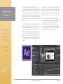
After reviewing the feedback from the initial wireframes, we then moved onto developing the tablet
interface on Adobe Illustrator.
The following pages show these interface designs
and are annotated with extra information showing
the main functionalities and uses for each section
of the interface.
The image to the right shows the glasses interface
for the “Job” section and also the corresponding
screen on the tablet app. The Glasses will display
the step number and any safety symbols that
relate to that stage of the task. The tablet will show
text-based instructions, along with helpful images,
and any past report findings that past users have
inputted.
iPole 2014 Team Mcfly
Page 54
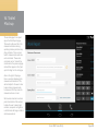
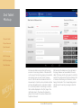
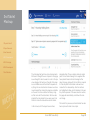
The original plan for the tablet during reporting
was to show the operating data of the turbine
since the last service, this would aid the engineer
to see how the turbine has been performing and
write the reports accordingly. These graphs would
be shown on the right of the tablet.
However after some feedback, we decided to
change this. We thought that the best way to use
this space would be to provide average results
or recommended results for measurements. This
way the engineer can compare their findings and
note down if everything is correct. We also decided to add in a numeric pad to allow the user to
input numbers quickly, as voice recognition does
not seem to recognise numbers too well.
iPole 2014 Team Mcfly
Page 55
This final section shows the “Report” section of the
interface. This is where the user will be in contact
with the support centre. The support centre will
see a live stream from the users glasses so they
can explain a problem. The worker in the support
centre can then send over any relevant helpful
images to aid the worker in completing their task.
The user would then be able to view these attachments and share them with their team mates.
iPole 2014 Team Mcfly
Page 56
Interaction
Workflow
To aid with understanding the relationship between the glasses and tablet app, we have created a possible ‘conversation” between the two.
The glasses will talk to the user and understand
commands given to it.
This will allow the user to work hands free and also
allow them to have as much information as they
need available to them. Every users experience
with these devices will differ, as everyone has
different levels of expertise and knowledge.
(Conversation continues over 2 pages)
iPole 2014 Team Mcfly
Page 57
iPole 2014 Team Mcfly
Page 58
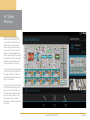
1st Tablet
Mockup
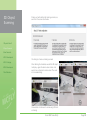
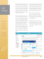
We decided to first mock up the tablet interface.
This was because the glasses interface is fairly
simple and we wanted to pay special attention to
the content on the tablet and how this will provide
a more detailed and enhanced version of the
glasses interface. The main use of the tablet is to
provide extra information, in a different way, due
to various limitations with the smart glasses we are
using.
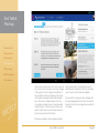
The first screen that we looked at was the job
instructions section of the app. This page includes
a progress bar at the top of the page as a visual
indication of how close to completion the overall
task is.
Below that in the main content area is the current
step that the user is on. This will be supplied in a
series of steps in text. This is because text cant
be displayed well on the smart glasses, and so incorporating text into the tablet app will be a great
help to the user.
In the “past report findings” this will help the user
because it could provide an answer to a problem
without the need of contacting external specialists.
Below the instructions we have the helpful images.
This is a section of images that have been sent
to the users in the past, or images taken by other
workers that relate to the step they are on. This
is how our user manuals will grow, this is user
generated content that will be helpful to the users
situation.
On the right there is the “past report findings” This
section will be again user generated. When filling
in the report, the user will be able to select various points that are a common problem, and these
points will then appear in future job manuals
iPole 2014 Team Mcfly
Page 59
1st Tablet
Mockup
The second page for our ipad
app is the Work Report page.
This is where the user fills in the
measurements taken during
reporting and also points out any
other problems. There is a text
field for measurements and also
extra comments. These extra
comments can be “starred” (as
mentioned on the previous page)
and will then appear in the “past
report findings” on the Job page.
Also on the right of the page
there is a section displaying the
measurement tolerances. This
will be helpful for the user to refer
to when taking measurements
to make sure that they know the
measurements are correct.
We have also inserted a numeric
pad in the bottom of this section
to allow the user to easily input
numbers, as speech recognition
is not the best with large numbers
and measurements.
iPole 2014 Team Mcfly
Page 60
1st Tablet
Mockup
Finally is the job assistance
screen for the tablet app. This
is the section in which the user
will be able to call an external
helper and request information
to be sent to them over the wifi
network. The users glasses will
stream video straight to the external helper so that they can understand the current problem and
send information accordingly.
The main attachments will appear
in a list on the right hand side of
the page, the user can then select these attachments and view
them in more detail.
There is also the option to share
the images with colleges on this
page, so that if one member of
the team gets a helpful images,
they can then send this to the
other workers they are with to
help them to understand the solution better.
iPole 2014 Team Mcfly
Page 61
1st Mockup
Feedback
Mockup Feedback points.
1.Physical Kickoff
2.Project Research
3.User Research
4.2016 Development
5.2016 Prototype
6.2024 Development
7.Final Reflection
We all discussed the mockups ides over Skype
and decided on the following points:
•The main feedback points for all pages mainly
concerned the navigation, the current style is not
in keeping with android guidelines and so this
will have to be changed. Also for the instructions
it was recommended that we add in some “previous/next” buttons to allow the user to manually
move back or forwards.
•It was pointed out that on every page, the text
seems to be too small for a tablet, this will need to
be examined and improved in the next iterations.
This application is being designed for a 10inch
tablet and so we will have to ensure everything is
correct.
•The main feedback for the “report” page was to
change the “star” icon, this is mainly because this
is usually associated with something being good,
and not a common problem. Also the measurement fields should be shortened, this is because
the user may think they need to input more information because of the size of the text field. Finally
it was recommended to remove “enter” from the
numeric pad and replace this with a symbol just to
aid with non-English users and to reduce confusion. All of these points will be taken into consideration when we take a second look at the design of
this app.
iPole 2014 Team Mcfly
Page 62
2nd Tablet
Mockup
1.Physical Kickoff
2.Project Research
3.User Research
4.2016 Development
5.2016 Prototype
6.2024 Development
7.Final Reflection
It became apparent to us that we would need to
design a log-in page for the worker, each worker
would have their own identification number and a
password to gain access into the app.
we should have taken into account earlier. To
make amends for this, we have used a colour
pallet of blues and silvers to follow Alstom’s brand
colours.
With the new designs we wanted to try our best
to follow the given feedback in order to make the
app as functional as possible.
One main thought concerning the aesthetics of
the app was the overall look. Some of us though
it looked too dark and it didn’t really follow any of
the company colours and design - something that
iPole 2014 Team Mcfly
Page 63
2nd Tablet
Mockup
1.Physical Kickoff
2.Project Research
3.User Research
4.2016 Development
5.2016 Prototype
6.2024 Development
7.Final Reflection
Here is the second iteration of the “job” screen. As
you can see there have been some large changes
to this page. The main change is the addition of
the navigation at the top of the page. The navigation has been changed to follow Android guidelines. There is now a tabbed system at the top
for navigation to allow the user to navigate easily
through the app. This also frees up more screen
space, before, there was a lot of space taken up
by the chunky buttons at the bottom.
onto the instructions, this will allow the user to
switch between instructions if they do not want to
use the voice control that will be available.
The layout of the images has also changed, with
the being displayed down the right. The user will
be able to click on these images and view them in
more detail.
We have also added in some navigation buttons
iPole 2014 Team Mcfly
Page 64
2nd Tablet
Mockup
1.Physical Kickoff
2.Project Research
3.User Research
4.2016 Development
5.2016 Prototype
6.2024 Development
7.Final Reflection
We have also taken a second look at the report
screen to iron out any problems. It has been difficult to keep in the idea of a growing manual whilst
also making it easy to report certain measurements. To do this we have included a field for a
measurement, a field for extra comments and also
we have changed the star to a tick box to state if
it is a common problem. If something is common
then it will be displayed on the “job” page in the
right-hand column. This allows the manuals to
grow with comments from workers that are both
helpful and relevant.
We have kept the tolerances on the right side of
this page, however we have added in an extra
detail. That being a traffic-light system to notify the
worker if the measurement they have taken is within tolerance. Red being not in tolerance, amber
being on the border. The corresponding section
will light up with a warning message to alert the
worker.
iPole 2014 Team Mcfly
Page 65
2nd Tablet
Mockup
1.Physical Kickoff
2.Project Research
3.User Research
4.2016 Development
5.2016 Prototype
6.2024 Development
7.Final Reflection
Finally we have the assistance page for the tablet app. Not too much has changed on this page
apart from aesthetic changes. The assistant will
still be able to share images with the worker.
These will appear on the right. The worker will ten
be able to click on these images and view them in
more detail, and also share them with other
workers.
iPole 2014 Team Mcfly
It is also worth noting the addition of part of the
Alstom logo in the top left corner of the page,
this is just a small detail to relate the app back to
Alstom. Also we have added in a small avatar in
the top right just as an indicator of who is using
the app. The user will be able to click on this to
reveal the option to log out of the app.
Page 66
2nd Mockup
Feedback
Mockup Feedback points.
1.Physical Kickoff
2.Project Research
3.User Research
4.2016 Development
5.2016 Prototype
6.2024 Development
7.Final Reflection
We all discussed the mockups ides over Skype
and decided on the following points:
•Most of the points were positive for this iteration
of the app. There has been a definite improvement
to the look of the app and some of the functionality
has been improved.
•We should also add in the actual instructions
from the manual Alstom have gave us. At the
moment we have useless information that has no
context!
•Small details such as buttons and icons could be
changed to make the app follow a more ‘flat’ look,
however the app must still be user friendly.
•Also we should think about the tools the worker
will use. These are in the instructions so imagery
will be helpful for this.
•The Report page still needs to be improved, at
the moment it is still a little confusing.
•Also we should remove the numeric pad on the
report page and make it only appear when the
user is inputting numbers. There is no need for it
to be there all the time.
•We should add in an icon to show the glasses
are paired with the tablet.
•Also an icon to allow the user to activate voice
commands.
iPole 2014 Team Mcfly
Page 67
3rd Tablet
Mockup
1.Physical Kickoff
2.Project Research
3.User Research
4.2016 Development
5.2016 Prototype
6.2024 Development
7.Final Reflection
There was not much feedback to take in to account when it came to the login page for the app.
We decided to just look at the aesthetics in a little
more detail. We had a look at the current visual
identity for Alstom and decided to include the detail at the bottom of the page because of this. This
shape is on all of their promotional material, and
also the signage around their factories.
iPole 2014 Team Mcfly
We also added in a low opacity version of the “O”
from the logo just as an extra detail in the background.
Page 68
3rd Tablet
Mockup
1.Physical Kickoff
2.Project Research
3.User Research
4.2016 Development
5.2016 Prototype
6.2024 Development
7.Final Reflection
We have also added in this extra page to allow
the user to connect the tablet to the glasses they
are wearing. This screen will appear after login
and will display a list of all nearby glasses that
are available to connect. Once the user selects
their glasses, a notification will be sent to them to
connect the two. Once the user accepts this then
the two will be able to work together.
iPole 2014 Team Mcfly
This screen also gives the user the ability to only
use the tablet if they want. The tablet is more than
capable of showing the user what to do on its
own. This puts the user in control of the information they will receive.
Page 69
3rd Tablet
Mockup
1.Physical Kickoff
2.Project Research
3.User Research
4.2016 Development
5.2016 Prototype
6.2024 Development
7.Final Reflection
The Job page has had a few more improvements.
We have re-thought the use of space on this page,
as we thought 3 columns was too much in the previous designs. We had never thought of the page
as a scrollable area and had tried to squeeze everything into one small section. However we have
now changed this, making the page be scrollable
so the user can have a closer look at any images that come with the instructions. We have also
inputted the instructions that we were given from
Alstom to make the manual have some context.
In the manual, all of the steps have numbers
iPole 2014 Team Mcfly
alongside them. These numbers relate to certain
parts of a technical drawing that is supplied. We
have placed these technical drawings further
down the page, along with the tool that is required
for that step and the animation video we have
created for the disassembly. Also the numbers
are highlighted in blue, which indicates to the user
they can be pressed. If the user selects a number,
the page will automatically scroll down the relevant image.
The look of the previous and next buttons has also
been improved to look more simple.
Page 70
3rd Tablet
Mockup
1.Physical Kickoff
2.Project Research
3.User Research
4.2016 Development
5.2016 Prototype
6.2024 Development
7.Final Reflection
The layout of the Report page has been completely changed. We have looked at the instructions
from Alstom and inputted the measurements that
need to be taken. We have added in fields for the
measurement, the expected measurement, the
tolerance and also the status of the measurement.
This is similar to the previous designs but it is now
much more user friendly and easier to understand.
We have also added in the Action Taken field,
which allows the user to state weather they have
replaced a part or not.
iPole 2014 Team Mcfly
We have also added in a Damaged Part form that
the user can fill in if there are any other parts that
are damaged. This is a much better way of allowing the manuals to grow, if there is any part damaged, they can state which part, add notes and
state the action taken.
Page 71
3rd Tablet
Mockup
1.Physical Kickoff
2.Project Research
3.User Research
4.2016 Development
5.2016 Prototype
6.2024 Development
7.Final Reflection
Again we have kept the Assistance screen fairly
simple. However we have changed a few things.
We have made the right column smaller, as these
are really just thumbnails. This allows for a larger
selected image that the user can see in a lot more
detail. We have also added in a bottom bar that
states some information about the image and also
an ability to share the image. When selected a list
of the co-workers will appear and allow the user to
share an image.
We have also taken into account other points for
improvement by adding in an icon to display if the
glasses have been paired with the tablet, and also
an icon to allow the user to select if they wish to
use voice controls.
iPole 2014 Team Mcfly
Page 72
Further Glasses Research
Glasses
Interface
1.Physical Kickoff
2.Project Research
3.User Research
4.2016 Development
5.2016 Prototype
6.2024 Development
7.Final Reflection
The feedback from the glasses wireframes was
all positive and so we decided to take forward the
current wireframes that we have created. However, we wanted to ensure that our interface was as
easy to use as possible. To make sure of this, we
conducted some extra research into the colours
that could be displayed on the glasses, we anted
to know what worked and what didn’t.
To the right is some of the findings from this exercise. We established that white was the clearest
colour to use, especially on a blank background.
Also red and blue seemed to produce some clarity.
To conduce with this research, we decided to use
white to display the ‘active’ state of the glasses
and anything that needed to be clear. We decided to use blue as a secondary colour to use for
the inactive icons and information that was less
important.
On the following pages are the final mockups for
the interface, displayed as the user would see
them through the glasses.
iPole 2014 Team Mcfly
Page 73
Glasses
Interface
1.Physical Kickoff
2.Project Research
3.User Research
4.2016 Development
5.2016 Prototype
6.2024 Development
7.Final Reflection
Here is the glasses interface for the Job section.
We have made a few improvements to the wireframes. The main one being we have removed the
step number. This is because it gives no indication of progress. To solve this we have included a
progress bar. This will match up the progress bar
on the tablet interface to allow the worker to know
how far along they are and how much more work
they have to do.
This page will also display the 3D renders of
the machine disassembly to aid the user. These
animations will appear in the middle of the users
view. The user will be able to show or hide these
through voice commands.
In the bottom right we also have some safety
icons. These will change depending on the step.
iPole 2014 Team Mcfly
Page 74
Glasses
Interface
1.Physical Kickoff
2.Project Research
3.User Research
4.2016 Development
5.2016 Prototype
6.2024 Development
7.Final Reflection
Second we have the report section of the interface. This page will allow the worker to take any
images or videos to insert into the report. This
page is mostly clear in the middle to allow the user
to see through the glasses interface to concentrate on the report that will be displayed on the
tablet.
iPole 2014 Team Mcfly
Page 75
Glasses
Interface
1.Physical Kickoff
2.Project Research
3.User Research
4.2016 Development
5.2016 Prototype
6.2024 Development
7.Final Reflection
Finally we have the assistance page. This page
will be mostly blank, but will show the user that
they are streaming video to the support centre.
This will be shown by the icon in the bottom left
glowing to show it is active.
iPole 2014 Team Mcfly
Page 76
3rd Tablet
Mockup
1.Physical Kickoff
2.Project Research
3.User Research
4.2016 Development
5.2016 Prototype
6.2024 Development
7.Final Reflection
We have also created these two pop-up notifications for the glasses interface. These will be
triggered when the user attempts to connect the
glasses to the table and when they call the support centre.
The calling notification will be displayed when the
user is calling the support centre. This will only be
displayed for a short period of time whilst the call
is actually connecting.
The connect notification will allow the user to say
“accept”/”yes” or “decline”/”no” to connect the
glasses or not.
iPole 2014 Team Mcfly
Page 77
Once we had created out final designs for
both the tablet and glasses interfaces, it was
time to start creating interactive prototypes
to showcase our work. We have decided to
create a semi-functional glasses interface and
also a tablet interface mockup.
iPole 2014 Team Mcfly
Page 78
Disassembly
Animation
Creation
As you will be able to see from our interface
designs, we have also created a 3D disassembly animation video. This is to aid the worker with
any steps that they may be unsure of. They will
be able to request to see the animation and it
will show them the job step-by-step with detailed
animations.
We first drew out a storyboard for the disassembly
animation (below) this was used to create the final
animation.
We created the animation for the whole disassembly, however we will only show parts of this in our
prototype.
1.Physical Kickoff
2.Project Research
3.User Research
4.2016 Development
5.2016 Prototype
6.2024 Development
7.Final Reflection
iPole 2014 Team Mcfly
Page 79
Disassembly
Animation
Creation
Once the storyboard was complete we could then
begin to create the animation. We created the 3D
model of the valve and imported this into Cinema
4D so that the model could be animated.
After that we inserted the lighting around the
model and created the camera movements to pan
around the model to show it from various angles to
allow the user to understand the step fully.
After that the parts were animated, for example
the screws, to show the step in more detail and to
give an accurate visual representation.
Finally we cut the animation up into separate parts
for use within the user manual.
Below: Cinema 4D in use
1.Physical Kickoff
2.Project Research
3.User Research
4.2016 Development
5.2016 Prototype
6.2024 Development
7.Final Reflection
iPole 2014 Team Mcfly
Page 80
Tablet
Prototype
1.Physical Kickoff
2.Project Research
3.User Research
4.2016 Development
5.2016 Prototype
We began creating the tablet prototype in a program called Proto.io. This is a fairly new application that allows the user to create interactive app
mockups for demonstration and user testing purposes. It also allows you to download an accompanying android or IOS app for you to showcase
the interfaces on an actual tablet or smart phone.
This was perfect for our project.
Proto.io has a pretty simple learning curve and
so it was not too difficult to learn as we created
the prototype. It mainly functions on setting out
the main screens for the application. Within each
screen you can place certain containers. These
containers can be edited to be interactive, such
as scrollable and they can also be shown or
hidden on demand through simple commands.
For example “If button X is pressed then show
container Y”. This allows the prototyping to be a
fairly quick process, but the final product is fully
functional and impressive if you put the time and
effort in.
We have made sure to include everything needed
in this interactive prototype to allow the user full
freedom of the app when testing. It allows the user
to navigate through the app from the login screen,
to connecting the glasses, to the job instructions,
report section and also the assistance screen.
Below is a screen shot of the job instructions
page. All of the blue squares on the page are
interaction areas, to allow the user to tap, scroll
or swipe to allow the user to interact as if it was a
fully function application.
On the left of the screen shot you can see the list
of items that there are on the screen. This screen
has a number of containers placed on it to allow
the screen content to change when a certain button is pressed.
6.2024 Development
7.Final Reflection
iPole 2014 Team Mcfly
Page 81
Tablet
Prototype
1.Physical Kickoff
2.Project Research
3.User Research
4.2016 Development
5.2016 Prototype
6.2024 Development
7.Final Reflection
To the right is an example of a container on this
page. This container includes the detailed step
instructions and also other information, such as
the cross-section diagrams of the valve, the tools
needed for that step and also the video that we
have created. This container is scrollable to allow
the user to look through the assets and look at
them if needed. The interaction areas at the top
are also there to aid user interaction. If the user
presses on one of the blue words, the container
will automatically scroll down to that section. So
if they click “view step video” it will scroll down to
the video and allow the user to view it. We have
also added in the actual video into this prototype
so everything works. However, this brings us
to one of the limitations of Proto.io. For all it is a
fantastic platform for designing prototypes, the
videos take a long time to load, even on a fast
WiFi network. We have found that there is no fix
for this and other groups have mentioned similar
problems. The file sizes of these videos are very
small (4mb) yet the app cannot load them very
quick. This is a shame but the user can still get a
good idea of how the application works and how it
could be used in a working environment.
We have also included a web-based version of
this prototype. This can be found at:
http://platzh1rsch.ch/ipole2015/
The video does not play but the rest of the app
should be fully functional.
iPole 2014 Team Mcfly
Page 82
Glasses
Prototype
On the following pages are the steps that we have taken to create the Glasses Prototype. All code snippets are shown in Blue Text
Create Trackable / 3D Model in Metaio Creator:
1.Physical Kickoff
2.Project Research
3.User Research
First of we simply create a new project in Metaio creator. We use the Alstom
logo as an image trackable and a 3D model of the steam turbine as the AR
object to display.
Add lighting
Because Metaio creator does not apply any lighting to 3D models by default,
we have to do that ourselves using Metaio’s ArelJS.
4.2016 Development
5.2016 Prototype
6.2024 Development
7.Final Reflection
AREL Script to add light sources to the scene
iPole 2014 Team Mcfly
Page 83
Glasses
Prototype
Export to App for Eclipse
Now we want to export our scenario to Eclipse, to get more possibilities to
interact with the android system. We can do that via Export App > SDK App
> Android Eclipse project.
1.Physical Kickoff
2.Project Research
3.User Research
4.2016 Development
5.2016 Prototype
6.2024 Development
7.Final Reflection
Export assistant of Metaio Creator
We can then import the just created project into Eclipse and start to customise it.
The configuration which trackable to look out for and which 3D model to display is stored in the assets/index.xml file. So it is no problem to replace the
trackable or the 3D model later on.
iPole 2014 Team Mcfly
Page 84
Glasses
Prototype
Adding GUI elements
The next step was adding all the GUI elements from the glasses interface we
all agreed on. Thanks to Metaio ArelJS this is quite easy. All the ArelJS files
can be found in assets/html/arel.
1.Physical Kickoff
2.Project Research
3.User Research
4.2016 Development
5.2016 Prototype
6.2024 Development
7.Final Reflection
ArelJS files in the previously exported eclipse project
iPole 2014 Team Mcfly
Page 85
Glasses
Prototype
First of we needed to add all the icons to the img folder and create the
structure of the interface in index.html using arel_style.css to position and
style everything. In a next step we then needed to add interactivity based on
touch events. We added this into logic.js. The workflow was similar to creating a website.
1.Physical Kickoff
2.Project Research
3.User Research
4.2016 Development
5.2016 Prototype
6.2024 Development
7.Final Reflection
Screenshot of the glass interface with all GUI elements added
iPole 2014 Team Mcfly
Page 86
Glasses
Prototype
1.Physical Kickoff
2.Project Research
3.User Research
4.2016 Development
5.2016 Prototype
6.2024 Development
7.Final Reflection
Set up Javascript Bridge
As the whole ArelJS interface is running in a WebView container overlaying the camera image, we need to be able to control this WebView from
the native Java code of the app. All we need to do to enable this, is to
add a Javascript interface to the WebView in com.ipole.mcfly.steamvalve.
ARELViewActivity.java.
@SuppressLint(“SetJavaScriptEnabled”)
protected void onStart()
{
super.onStart();
// attach a WebView to the AREL interpreter and initialize it
mARELInterpreter.initWebView(mWebView, this);
mWebView.getSettings().setJavaScriptEnabled(true);
mWebView.addJavascriptInterface(new JsObject(), “myInterface”);
}
//Here you define all the methods that you want to access from Javascript
private class JsObject {
@JavascriptInterface
public void showToast(String s){
Toast.makeText(getApplicationContext(), s, Toast.LENGTH_SHORT).
show();
}
}
Code to create Javascript interface in the native code
Call Java from Javascript
We can now easily call Java code from Javascript:
window.myInterface.showToast(“job description”);
Call JavaScript from Java
The Javascript Bridge also works the other way around, so we can now call
Javascript functions from Java code. The only requirement is that the Javascript function is public. This is important if we want to change the look of our
application based on events in the native code.
myWebView.loadUrl(“javascript:myjavascriptfunc()”);
iPole 2014 Team Mcfly
Page 87
Glasses
Prototype
1.Physical Kickoff
2.Project Research
3.User Research
4.2016 Development
5.2016 Prototype
6.2024 Development
7.Final Reflection
Voice Control / Speech Recognition
The next step was adding voice control, so that
the user can interact with the app by using voice
commands to switch between views and react to
questions and dialogs.
Requirements
braucht RECORD_AUDIO permission http://developer.android.com/reference/android/
Manifest.permission.html#RECORD_AUDIO
Solutions
Android SpeechRecognizer
Google is providing every developer with a already functional SpeechRecognizer class through
their Android SDK which was added already in
Android 2.2 (Froyo). The service requires Google
services to be installed and sends all the voice
data to Google servers for evaluation. We read
that it is also possible to download all the speech
recognition functionality to ones own device to
make it available offline, but we did not test this.
Source
Android Dev Guide, SpeechRecognizer class http://developer.android.com/reference/android/
speech/SpeechRecognizer.html
iPole 2014 Team Mcfly
CMU Sphinx
CMU Sphinx is an open source toolkit for Speech
Recognition developed by Carnegie Mellon University (CMU). It is able to work offline and there
are libraries for various different platforms, one
of them of course being Android. It is possible to
create your own vocabularies and language models and it therefore works with all kinds of different
languages.
Source
CMU Sphinx Website http://cmusphinx.sourceforge.net/
Conclusion
While Google SpeechRecognizer may be more
precise in recognizing speech commands, it has
other limitations: it only works online (although
you could download all the speech recognition
data) and “always-listening” is limited to 10s (to
decrease unnecessary server traffic). Also you
need to have the google services installed on your
smartphone, which the Epson glass does not have
per default.
Sphinx on the other hand is a platform independent open source Java Framework that works
offline and with lots of different languages.
Page 88
Glasses
Prototype
1.Physical Kickoff
2.Project Research
3.User Research
4.2016 Development
5.2016 Prototype
6.2024 Development
7.Final Reflection
CMUSphinx.
All modern descriptions of speech are problematic to some degree. The only way to have a good
speech recognition, is to somehow train your
program with tons of voice data. Luckily for us,
there are existing models for CMU Sphinx for the
English language.
Keyword spotting.
Always listening to everything being said, can
cause a lot of errors and strange behavior. A
better solution would be to do it like Google Glass,
which seems to have some kind of different “listening states” and trigger commands to switch
from one of these states to another. While in one
state / context, the device only pays attention to
the commands that matter for that state and ignores everything else. This is also called keyword
spotting and is what we are going to use for our
prototype.
Adding pocketsphinx-android to the prototype.
CMU Sphinx is providing a library specifically
created for Android called pocketsphinx-android.
It also contains a demo application demonstrating
the basic features. The grammars defining what
words the program should listen to can be found
in assets/sync/models/grammar
File structure of the pocketsphinx-android demo
application
Setup grammars
CMU Sphinx is using the JSpeech Grammar Format (JSGF), which is a standard format to define
grammars used in speech recognition. You can
find the w3c standard at http://www.w3.org/TR/jsgf
Unfortunately the Pocketsphinx JSGF compiler is
incomplete. While it is supporting all the important
functionality, it only supports one public grammar
per file, and it does not support importing.
iPole 2014 Team Mcfly
Page 89
Glasses
Prototype
State Diagram
The next step was adding voice control, so that
the user can interact with the app by using voice
commands to switch between views and react to
questions and dialogs.
1.Physical Kickoff
2.Project Research
3.User Research
4.2016 Development
5.2016 Prototype
6.2024 Development
7.Final Reflection
State diagram showing the different states of
the glass prototype and the voice commands to
change from one to the other.
iPole 2014 Team Mcfly
Page 90
Glasses
Prototype
1.Physical Kickoff
2.Project Research
3.User Research
4.2016 Development
5.2016 Prototype
6.2024 Development
7.Final Reflection
Grammars
Based on the state diagram we went on to create
the different grammars for the different states.
Basically every state knows the commands “Reporting”, “Job Description” and “Assistance Call”,
so you can always switch directly to another state.
In the User Manual state, you have two additional
commands “next Step” and “previous Step” to
proceed through all the steps.
For example the user manual grammar looks like
this:
Screen recording for demo video.
Since Android KitKat (4.4), Android devices now
have a screenrecord function that makes it very
easy to make screen capture videos. Unfortunately the Epson glass is running Android 4.0.4 so we
had to use a Nexus 7 tablet running Android 4.4.
#JSGF V1.0;
grammar mcfly.manual;
Source: http://www.phonearena.com/news/Howto-record-your-screen-on-Android-4.4-KitKat_
id49133
public <command> = next step | previous step |
job description | reporting | assistance call;
The first line is just a comment, the second one is
the name including the namespace of the grammar. On the last line is the definition of the grammar. “|” means “or”, so if any of these terms are
detected, there will be an event in the application.
‘adb -s 015d324925580a13 shell screenrecord /
sdcard/alstom1.mp4’
stop capture with CTRL-C
‘adb pull /sdcard/alstom1.mp4 D:/alstom1.mp4’
Source code
Of course this document does not contain all the
source code of the glass prototype. However,
all our source code is hosted in a private repository on github.com. We would be more than happy
to provide anyone interested with a copy. Just
write an email to:
[email protected].
iPole 2014 Team Mcfly
Page 91
2016 Video
Creation
1.Physical Kickoff
2.Project Research
3.User Research
4.2016 Development
Once we had completed the interfaces and
prototypes for both the glasses and tablet interfaces, we wanted to create a short video to really
show the interaction between the two and how
they would complement each other. We wanted to
show a workflow of the two interfaces and how the
user would progress through a job using our two
interfaces.
To create this video we first began in After Effects.
We used this program to animate certain parts.
We had created a previous video in which we
attempted to show both interfaces on screen at
the same time, however this did not work because
you could not see exactly what was happening.
We used after effects to make the interfaces shrink
and grow to show when something was happening on that particular screen, you will see this in
the video.
We have used the still mockups of the glasses interface in the video and animated them slightly to
show how they would function and we have used
a screen capture from Proto.io to show the tablet
interface and how the user can interact with that.
We decided that the best way to communicate
the interactions between the glasses, tablet and
worker would be to have both visual and audio
representations. We wanted to display not only
the touch interactions of the tablet, but also the
voice command capabilities and how the user can
navigate through the application quickly.
5.2016 Prototype
6.2024 Development
7.Final Reflection
iPole 2014 Team Mcfly
Page 92
2016 Video
Creation
1.Physical Kickoff
2.Project Research
3.User Research
For the voice over, we wanted to make sure that
everything was as clear as possible for the audience to hear, and so we used a specialist Tascam
audio recording device to record a few small
voice clips. These clips were then edited to take
out any unwanted background noise and to make
the audio as clear and as clean ad possible.
Also because we are team McFly, we have used
a slight back to the future reference in our video,
that being the backing track. We have used an
instrumental version of “The Power of Love” that
was featured in the back to the future soundtrack
and movie.
Once the voice over was recorded everything just
needed to be put together, We used the program
iMovie to edit everything together. Although it is a
fairly basic program, it was all that we needed to
combine our audio track, video and also a backing track. We have also added ‘ducking’ to the
backing track, so that whenever the main voice
over is on, the backing track is lowered to make
sure the voice over can be heard perfectly.
A link to view the 2016 video can be found at the
beginning of this document in the “Business Summary” ( bottom of page 5).
4.2016 Development
5.2016 Prototype
6.2024 Development
7.Final Reflection
iPole 2014 Team Mcfly
Page 93
Running alongside our 2016 development, we
also had to focus on our design solution for
2024. We had to keep in mind our group aim
of providing the right information, for the right
person, at the right time. We also had to create a possible solution for Alstom in the future,
where almost anything could be possible.
iPole 2014 Team Mcfly
Page 94
2024 Choice
Of Technologies
1.Physical Kickoff
2.Project Research
3.User Research
4.2016 Development
5.2016 Prototype
6.2024 Development
7.Final Reflection
In order to develop our vision for 2024, we conducted research into different directions: We
looked at smart materials, holograms, wearable
technologies, brainwave technology, the internet
of things, smart glasses, smart contact lenses,
nanotechnology surfaces, holograms, projected
interfaces, etc. Everyone researched into a direction they were interested in and in the end we
presented our findings to each other.
In the next step, we started discussing which of
these technologies we could use to improve user
manuals in 2024.
From the beginning, brainwave technology was
a hot favorite. We were quite excited about the
new possibilities that this technology would bring.
We were convinced that with this technology, we
could save Alstom a lot of time – after all, if they
just had to “think” the report rather than write it by
hand, the whole process could be sped up considerably. However, after discussing things for a
while, we came to the conclusion that brainwave
technology would probably also come with a few
downsides. We imagined that the employees
would be quite skeptical about this technology.
After all, who could prove to them that the technology would only read the thoughts they used
to control the system. We could imagine that the
employees would have many questions regarding
this technology. For example: “If I had a bad day
at work and thought ‘I really should find another
job’ – would that send notification to HR straight
away?” It would be hard to prove to them that this
kind of thoughts would not be read.
So then, after discussing things for a while longer,
our solution for 2024 would consist of three key
components:
iPole 2014 Team Mcfly
•Internet of Things (IoT):
The machine is self-diagnosing, i.e. it continually
takes measurements and if something is out of
order, it sends a message via IoT. As a result, the
technician will know exactly what is broken and
will not have to spend time searching for the fault.
In addition, he will already know which parts will
need to be replaced. This will save Alstom a lot of
time (and, therefore, money).
•Smart materials:
The technicians will wear jackets made of smart
materials. Parts of the jacket can be used as a
screen, for example. This has the advantage that
the technicians no longer have to carry around an
additional device. All the devices are integrated:
Either in the jacket or in the safety glasses.
•Holograms:
The hologram will illustrate how to take the machine apart. For example, it shows the technician
how to remove the screw, and then the technician
removes it. Then, the hologram shows the technician the next step, etc.
Page 95
2024
Research
1.Physical Kickoff
2.Project Research
3.User Research
4.2016 Development
5.2016 Prototype
6.2024 Development
7.Final Reflection
Internet of Things (IoT)
The Internet of Things is no longer a futuristic vision: Large companies such as Cisco (http://www.
cisco.com/web/solutions/trends/iot/overview.html)
already offer IoT solutions for various industries. In
a press release dating from March 2014, Gartner,
the world’s leading information technology research and advisory company, even reckons that
“By 2020 the IoT Will Include 26 Billion Units”
Smart materials
There are many different types of smart materials
and first applications can be found in the medical
industry. For example, the NHS funded a unique
steerable catheter project that is based on shape
memory materials are used: “The device has
small pieces of shape memory alloy disposed at
its tip, each piece of metal is electrically heated,
as it become warm, it deflects the catheter tip in a
controllable and precise way.“
In her paper INTRODUCTION, CLASSIFICATION
AND APPLICATIONS OF SMART MATERIALS:
AN OVERVIEW (published in the American Journal of Applied Sciences in 2013: Sasmita Kumila
lists different types of smart materials, outlines
the self-adaptation characteristics of such materials and describes the resulting advantages: “By
changing their properties, smart materials can
detect faults and cracks and therefore are useful
as a diagnostic tool. This characteristic can be
utilized to activate the smart material embedded in
the host material in a proper way to compensate
for the fault. This phenomenon is called self-repairing effect.“ We think this is a very interesting
application of smart materials and one that could
help Alstom reduce down time.
iPole 2014 Team Mcfly
Holograms
There are also interesting developments in the
area of holograms. The British company Musion,
for example, is the company that produced the
famous “resurrection concert” of Tupac Shakur
in 2012. More recently, Musion was contracted
by the now Premier Minister of India, Narendra
Modi, during his electoral campaign. With the help
of Musion’s hologram technology, Modi simultaneously addressed audiences in 53 locations in
India during his speech in April 2014.
Furthermore, the application of holograms is
currently being tested in the medical field. A study
with the title of Medical Holography for Basic
Anatomy Training, which was published in 2013,
suggests that medical students who study using
holograms learn more effectively than students
who use traditional materials like paper handouts.
The study lists several factors for this improvement:
•The first is the “wow-factor”. Textbook handouts
are very commonplace and elicit little inherent interest subsequently. The medical holograms are a
novel technology [...]”. The same could be true for
manuals: holograms would be a novel technology
and make manuals more interesting.
Page 96
2024
Research
1.Physical Kickoff
2.Project Research
3.User Research
4.2016 Development
5.2016 Prototype
6.2024 Development
7.Final Reflection
•The medical holograms have the advantage of
being natively 3D, unlike textbook handouts. As
such, the medical holograms may be directly
translated to a mental image, while a 2D textbook
handout requires 3D reconstruction within the
working memory.” Again, the same could be true
for manuals: Understanding an animated 3D hologram would require less work than understanding
a technical 2D drawing of a machine.
•Finally, the medical holograms may simply provide superior visual capabilities due to their 3D
nature. Many anatomical structures are difficult to
conceptualize, such as the spatial relationships
between various blood vessels, the valves of the
heart, and the chambers of the heart. Medical
holograms provide additional 3D data to understand these relationships, such as depth cues.”
The same would apply to machines: Unlike the 2D
drawing of the machine, the 3D hologram would
provide spatial information that might be important
for the technician.
When discussing these points further, we all decided it would be a good idea to add in a drone
for the user, as at this point we were struggling
to find a way to integrate the holograms into the
solution. Our inspiration for this idea came in the
form of Weebo from the well-known film Flubber.
Weebo is a flying assistant for the professor in
this movie and would be a perfect addition for an
alstom worker in a future environment. The drone
would follow the worker around, displaying hologram images when needed and also pointing out
any details using a laser pointer.
iPole 2014 Team Mcfly
Weebo -From Flubber
Souces:
•http://www.gartner.com/newsroom/id/2684616
•http://thescipub.com/PDF/ajassp.2013.876.880.
pdf
•http://www.brunel.ac.uk/etc/research/biomedical-matrials/applications-of-smart-materials-for-medical-devices
•http://musion.com/?portfolio=tupac-coachella-2012-hologram
•https://www.youtube.com/watch?v=TF_LmujSteM
•http://www.zebraimaging.com/Portals/151303/
docs/Medical_Holograms_Whitepaper.pdf
Page 97
2024
System
Diagram
1.Physical Kickoff
2.Project Research
3.User Research
4.2016 Development
5.2016 Prototype
6.2024 Development
7.Final Reflection
Here is the system diagram for our 2024 solution.
The system relies on the Internet of things. The
user will be connect to both the assistant drone
and their smart clothing. These will in turn be
connected to the internet of things and also the
machine itself. The machine will be made from
smart materials, they will be able to detect a
problem and request maintenance.
iPole 2014 Team Mcfly
Page 98
2024
Storyboard
1.Physical Kickoff
2.Project Research
3.User Research
4.2016 Development
After we had conducted out research, we need
to start thinking about a possible scenario and
how we could present this in a promotional video.
This quick story board was drawn up to depict a
possible scenario in which all of our ideas would
come together.
In the storyboard below, the machine will be connected to the internet of things. It will be able to
detect when there is a fault and notify the support
centre of the problem. This will in turn trigger the
release of the needed parts. Once the new parts
are delivered, the worker will begin work on repairing the machine.
Finally, the user’s drone will assist the user by
showing holograms of information and pointing out
parts to aid with the work.
The worker will have a jacket that includes smart
materials on the sleeve, allowing for a display to
be shown. This will display instructions to the user.
This story board will be used to develop and create a promotional video showing our proposal for
2024.
5.2016 Prototype
6.2024 Development
7.Final Reflection
iPole 2014 Team Mcfly
Page 99
2024 Video
Creation
We wanted to create an animated video for our
2024 vision. To do this we have used the programs Adobe Illustrator and after effects.
We first wrote down a scripted storyboard to get
our ideas across, we decided to again use the
Tascam voice recorder to record a voice over to
narrate the story, as we felt this would be the best
form of communication.
1.Physical Kickoff
2.Project Research
3.User Research
4.2016 Development
5.2016 Prototype
6.2024 Development
7.Final Reflection
iPole 2014 Team Mcfly
Page 100
2024 Video
Creation
We then drew out some rough sketches of the
story board to get an overall idea of what parts we
had to create in Illustrator.
Below are a few examples of the sketches that
were created:
1.Physical Kickoff
2.Project Research
3.User Research
4.2016 Development
5.2016 Prototype
6.2024 Development
7.Final Reflection
iPole 2014 Team Mcfly
Page 101
2024 Video
Creation
These rough sketches were then taken into Illustrator and drawn out properly in vector form. This
would allow us to keep each individual part of the
drawings on separate layers so that they could be
animated separately. We went with a simple cartoon theme for the drawings, they are very basic,
but get the story across in a fun visual manner.
Below are the final images that we have used to
create the video with.
1.Physical Kickoff
2.Project Research
3.User Research
4.2016 Development
5.2016 Prototype
6.2024 Development
7.Final Reflection
iPole 2014 Team Mcfly
Page 102
2024 Video
Creation
We finished up the video in After Effects, animating the separate sections of the video and putting
everything together. The outcome is a strong
video that displays our 2024 concept and describes a potential scenario in which our vision will
exceed.
A link to view the 2024 vision video can be found
at the beginning of this document in the “Business
Summary” ( bottom of page 5).
iPole 2014 Team Mcfly
Page 103
1.Physical Kickoff
2.Project Research
3.User Research
4.2016 Development
5.2016 Prototype
6.2024 Development
7.Final Reflection
For us, the iPOLE project was intense, but rewarding, and we really enjoyed working on it.
and it was interesting to see how much we
could achieve in such a short amount of time.
We learned a lot about technologies and
wearables during this project, and thanks to
Alstom, we gained insight into a completely
new area.
iPole 2014 Team Mcfly
Page 104
Reflection
At the beginning of the project, we had to get to
know each other. We had to find out what skills
the team members had and what experience they
brought to the table. We also had to find out about
each other’s circumstances: who is studying full
time, who is studying part time, who is also working part time, etc.
Challenges
1.Physical Kickoff
2.Project Research
3.User Research
4.2016 Development
5.2016 Prototype
6.2024 Development
7.Final Reflection
Communication
Sharing knowledge
Given that the team was distributed across four
countries, we knew that communication would be
important. Having a weekly Skype call was a good
start, but we soon found that it was not enough.
That is when we decided to start using Slack,
which improved the communication a lot. We used
Slack to:
In order to share the knowledge between the
different team members, documentation was important: After each team meeting we sent out the
meeting minutes. They summarised what we had
discussed and what decisions we had taken. They
also listed the tasks each team member agreed to
complete by the next team meeting. We were also
careful to document our research findings: While
we presented them during the team meetings, we
also provided them in written form. This was useful
for three reasons: Firstly, it meant that everyone
could read them again in their own time, which,
given the complexity of the subjects, was often
necessary. Secondly, we could then include these
findings in our design document. And thirdly,
written documentation also helped bridging some
language barriers that we might have had.
•Give the rest of the team a heads-up on how we
were doing (for example: “I’m having some problems with the glasses; I can’t use them in developer mode”)
•Ask for opinions (e.g. “How could I improve the
video?”)
•Give feedback on the wireframes.
•Post links to important documents (Slack comes
with Google Drive integration, which was very
handy)
•Post interesting links.
•Discuss topics/problems in dedicated channels
so everyone could re-read the discussion and look
up stuff if they did not remember the details.
iPole 2014 Team Mcfly
Page 105
Reflection
1.Physical Kickoff
2.Project Research
3.User Research
4.2016 Development
5.2016 Prototype
6.2024 Development
7.Final Reflection
What went well
During the entire project, we really worked together, and the result is very much a team effort.
There are several aspects that had a positive
impact on our teamwork:
•All the team members showed a lot of initiative
and commitment. We did not feel that any team
member worked a lot more or a lot less than the
others. Everyone put in a lot of effort and this kept
us motivated.
•The team members were proactive. For example,
we never had long discussions as to who would
present during the review meetings, because
people volunteered to present. This meant that we
could spend our time and energy on the things
that really mattered (rather than spending them on
determining who would do what).
•During our weekly team meetings, we defined
the tasks that needed to be completed by the following week and then distributed them. We were
careful to clearly define the tasks and the deadline
(which was usually the next Thursday) so there
would not be any misunderstandings.
iPole 2014 Team Mcfly
•We notified the rest of the team in advance if we
saw that we would not be able to complete a task
in time (for example because the task turned out
to be more time-consuming than initially anticipated, or because we had exams).
•The team members were not afraid to ask questions or to ask for help.
•We had a very good feedback culture: The team
members were happy to both give and receive
constructive feedback. We did not just split the
tasks, complete them, and put everything together. Instead, we actively reviewed each others’
work and gave feedback on it. We are convinced
that this iterative approach improved our solution.
•We exchanged knowledge - not just between
team members, but also across teams. For the
animations, for example, we worked together with
another team.
•And last but not least: We were lucky that we all
just got along really well!
Page 106
Lessons Learned
Reflection
1.Physical Kickoff
2.Project Research
3.User Research
4.2016 Development
5.2016 Prototype
Looking back on this project, we would try to keep
the tools to a minimum. For example, we used
Trello as well at the beginning to assign tasks, but
it turned out that this created overhead. After a
few weeks, we just stated the to dos in our meeting minutes and crossed them out when they were
completed.
We would take inspiration from critical feedback,
but do not let it destroy our vision completely.
There were many coaches and every one of them
had their own ideas about how the teams should
take on the task. As a team, you have to have a
vision and stick to it. While constructive feedback
is always welcome, it is hard to please everyone.
It took us a while to realise that and we probably
lost some time at the beginning of the project due
to this.
Slack in use
6.2024 Development
7.Final Reflection
iPole 2014 Team Mcfly
Page 107