1
INFORMATION SOCIETY TECHNOLOGIES
(IST)
PROGRAMME
Technical Report
Project acronym: SmartSketches
Project full title: SmartSketches: A Multimodal Approach to
Improve Usability in the Early States of Product Design
Contract no.: IST-2000-28169
DELIVERABLE: D 18a SketchAR User Manual
User Manual
D18a - 2004/10/07
P. Santos, A.Stork
Deliverable
DELIVERABLE Nº
NAME:
WORKPACKAGE:
LEAD PARTICIPANT:
TYPE:
DATE:
CIRCULATION:
18a
SketchAR User Manual
4
IG
Report
2004 , 09 , 21
Public
Executive Summary
SketchAR is one of the first immersive design and modeling systems for early stages
of product design. It combines precise optical tracking with interaction on an
accurate CAD model, which is not just a triangle or subdivision surface model.
This document represents the SketchAR User Manual.
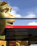
Figure 0: A car body sketched with SketchAR in a few minutes
Page 2 of 90
User Manual
D18a - 2004/10/07
P. Santos, A.Stork
The SketchAR User Manual is intended as a guide for the user to set-up a working
SketchAR environment as well as getting to know how all available features work. It
is split up as follows:
•
•
•
•
•
•
Hard- and Software requirements
CD content
Hardware Setup
Software Setup
Multimodal Interaction Techniques
Functionality:
o File Operations
o Package Model Editing
o Editing Operations
o Geometry Creation
o Geometry Modification
o Supporting Operations
o Network Collaboration
Please note that additional information can be found on the installation DVD (D17).
Page 3 of 90
User Manual
D18a - 2004/10/07
P. Santos, A.Stork
Content
1
INTRODUCTION ................................................................................................. 8
2
HARD- AND SOFTWARE REQUIREMENTS..................................................... 9
3
DVD CONTENT ................................................................................................ 10
4
SKETCHAR HARDWARE SETUP ................................................................... 11
4.1
Rendering Systems ................................................................................................. 11
4.1.1
Stereovision (active / passive stereo) ................................................................... 11
4.1.2
Virtual Reality Setup............................................................................................ 12
4.1.3
Augmented Reality Setup..................................................................................... 13
4.2
Tracking System..................................................................................................... 14
4.3
Interaction Devices................................................................................................. 16
5
5.1
SOFTWARE SETUP ......................................................................................... 18
SketchAR Software Architecture ......................................................................... 18
5.2
XML Configuration File........................................................................................ 19
5.2.1
Calibrating the pen ............................................................................................... 21
5.2.2
Calibrating the PIP ............................................................................................... 22
5.2.3
Speech Recognition.............................................................................................. 23
5.3
User Kit Configuration .......................................................................................... 24
5.3.1
Devices ................................................................................................................. 24
5.3.2
Display ................................................................................................................. 24
5.3.2.1 Desktop............................................................................................................. 24
5.3.2.2 Active Stereo .................................................................................................... 25
5.3.2.3 Passive Stereo................................................................................................... 25
6
MULTIMODAL INPUT METHODS.................................................................... 26
6.1
Pen Interaction ....................................................................................................... 26
6.2
Tracked Artifact..................................................................................................... 26
6.3
PIP – Personal Interaction Panel.......................................................................... 27
6.4
Pie Menu / Ring Menu ........................................................................................... 28
6.5
Speech Recognition / Synthesis ............................................................................. 30
6.6
Implicit Gesture Recognition ................................................................................ 30
Page 4 of 90
User Manual
D18a - 2004/10/07
P. Santos, A.Stork
6.7
Draggers & Sliders ................................................................................................. 31
6.8
3D Picking & Snapping.......................................................................................... 32
6.9
Virtual Paper Metaphor ........................................................................................ 33
7
7.1
SYSTEM FUNCTIONALITY.............................................................................. 34
File Operations ....................................................................................................... 34
7.2
Package Model Editing .......................................................................................... 34
7.2.1
Package Model Parameters .................................................................................. 35
7.2.2
Package Model Constraint Check ........................................................................ 36
7.3
Geometry Creation................................................................................................. 36
7.3.1
Curve Creation ..................................................................................................... 37
7.3.2
Eraser Pen............................................................................................................. 38
7.3.3
Automatic Curve Splitting ................................................................................... 38
7.3.4
Virtual Tape Drawing........................................................................................... 39
7.3.5
Surface Creation................................................................................................... 41
7.3.6
Primitive Creation ................................................................................................ 44
7.3.7
Scene Modelling and Assembly........................................................................... 46
7.4
Geometry Modification.......................................................................................... 50
7.4.1
3D Oversketching................................................................................................. 50
7.4.2
Constrained Oversketching .................................................................................. 51
7.4.3
Editing Control Points.......................................................................................... 53
7.4.4
Net Surface Oversketching................................................................................... 54
7.4.5
History based surface modification...................................................................... 55
7.4.6
Boolean Operations .............................................................................................. 56
7.5
Editing Operations ................................................................................................. 57
7.5.1
Select / Multiple Select ........................................................................................ 57
7.5.2
Move / Copy......................................................................................................... 58
7.5.3
Delete ................................................................................................................... 58
7.5.4
Multiple UNDO / REDO...................................................................................... 59
7.5.5
Material Editor ..................................................................................................... 59
7.6
Supporting Operations .......................................................................................... 60
7.6.1
Picking.................................................................................................................. 61
7.6.2
Snapping............................................................................................................... 61
7.6.3
Workplane ............................................................................................................ 61
7.6.4
Workplane to table ............................................................................................... 63
7.6.5
Mirrorplane........................................................................................................... 63
7.6.6
Clipping Plane ...................................................................................................... 64
7.6.7
Freeze Scene and View ........................................................................................ 65
7.6.8
Camera Zoom / Move .......................................................................................... 65
7.6.9
Ortho View........................................................................................................... 65
7.6.10
Four-View ............................................................................................................ 66
7.6.11
3D Layers ............................................................................................................. 67
Page 5 of 90
User Manual
D18a - 2004/10/07
P. Santos, A.Stork
7.7
Network Collaboration - SketchNET ................................................................... 67
7.7.1
SketchNET overview: .......................................................................................... 67
7.7.2
Connecting and Disconnecting to/from SketchNET............................................ 70
8
ANNEX A – REFERENCES.............................................................................. 71
9
ANNEX B - OPERATION TABLE ..................................................................... 73
10
ANNEX C – MENU REFERENCE.............................................................. 78
Page 6 of 90
User Manual
D18a - 2004/10/07
P. Santos, A.Stork
Figures
Figure 1: Hardware Setup Overview........................................................................................ 11
Figure 2: VR- Setup, active stereo scenario............................................................................. 12
Figure 3: VR- Setup, passive stereo scenario........................................................................... 13
Figure 4: AR- Setup ................................................................................................................. 14
Figure 5: Optical Tracking - ART Tracking System with ARTtrack1 cameras ...................... 15
Figure 6: Interaction Devices ................................................................................................... 17
Figure 7: SketchAR Architecture............................................................................................. 18
Figure 8: Abstract execution flow of operations...................................................................... 19
Figure 9: Pen Calibration ......................................................................................................... 21
Figure 10: PIP Calibration........................................................................................................ 22
Figure 11: Cyberstilo................................................................................................................ 26
Figure 12: Tracked Model Artifact .......................................................................................... 27
Figure 13: PIP & Pen ............................................................................................................... 27
Figure 14: Pie Menu................................................................................................................. 28
Figure 15: Pie sub-menu “SURF” animated pie menu ............................................................ 29
Figure 16: Context-sensitive pie menu..................................................................................... 29
Figure 17: Gesture based Input ................................................................................................ 31
Figure 18: Dragger
Figure 19: Slider ................................................................................ 32
Figure 20: SpaceMouse supporting the virtual paper metaphor .............................................. 33
Figure 21: Package Model........................................................................................................ 35
Figure 22: Package Model Constraints – Wheels .................................................................... 35
Figure 23: Package Constraint Check ...................................................................................... 36
Figure 24: Curve Creation........................................................................................................ 37
Figure 26: Automatic Curve Splitting...................................................................................... 39
Figure 27: Virtual Tape Drawing ............................................................................................. 40
Figure 28: Virtual Tape Drawing – Finger Tracking ............................................................... 40
Figure 29: Spline Extrusion...................................................................................................... 41
Figure 30: Skinning.................................................................................................................. 42
Figure 31: Net Surface ............................................................................................................. 43
Figure 32: Primitive Creation................................................................................................... 46
Figure 33: Assembly Parts ....................................................................................................... 49
Figure 34: Assembly I .............................................................................................................. 50
Figure 35: Assembly II............................................................................................................. 50
Figure 36: Curve Oversketching .............................................................................................. 51
Figure 37: Constraint oversketching principle ........................................................................ 52
Figure 38: Two possible curve extrusions................................................................................ 52
Figure 39: Constrained Oversketching..................................................................................... 53
Figure 40: Editing Control Points ............................................................................................ 54
Figure 41: Net Surface Oversketching ..................................................................................... 54
Figure 42: History based surface modification ........................................................................ 55
Figure 43: Boolean Intersection ............................................................................................... 56
Figure 44: Material Editor........................................................................................................ 60
Figure 45: Workplane positioned by dragger........................................................................... 62
Figure 46: Context pie menu allowing the work plane to be positioned in different ways ..... 62
Figure 48: Drawing in mirrored mode ..................................................................................... 64
Figure 49: Four-View............................................................................................................... 66
Figure 50: SketchNet................................................................................................................ 68
Page 7 of 90
User Manual
D18a - 2004/10/07
P. Santos, A.Stork
1 Introduction
The SketchAR User Manual (D18a) is intended as a guide for the user to set-up a
working SketchAR environment as well as getting to know how all available features
work. It is split up as follows:
•
Hard- and Software requirements: This section specifies the minimum
hardware requirements for SketchAR, the target operating systems as well as
supporting software.
•
CD content: This section describes the content of the Installation DVD (D17)
•
Hardware Setup: SketchAR relies on tracking and rendering hardware to run.
In this chapter the setup of the currently used optical tracking system is
explained and the user is given information on which alternative tracking
systems can be used. Furthermore the various scenarios in which SketchAR
can be used are detailed, namely the back-projection, virtual table and
augmented reality setup.
•
Software Setup: The software setup section mainly deals with the
configuration of SketchAR for the three above mentioned scenarios. The
calibration of tracked artifacts and the many ways of editing and merging
tracking input are explained in detail.
•
Multimodal Interaction Techniques: This section introduces the user to the
main interaction techniques used in SketchAR, which are usage of the tracked
model artefact, the pen interaction, the two alternate menu forms (PIP and
PIE menus) as well as speech I/O and gesture based interaction techniques,
draggers, sliders, picking, snapping and the usage of the spacemouse while in
four-view mode.
•
Functionality: This section covers all currently available features, specifying
which multimodal input techniques will invoke which functionality. The
features are grouped according to the following feature areas:
o File Operations
o Package Model Editing
o Editing Operations
o Geometry Creation
o Geometry Modification
o Supporting Operations
o Network Collaboration
The SketchAR Technical Report (D18b) elaborates on the user manual to describe
SketchAR from a technical point-of-view focussing on the specific details of the
hardware used and the implementation of the software.
Page 8 of 90
User Manual
D18a - 2004/10/07
P. Santos, A.Stork
2 Hard- and Software Requirements
SketchAR, the immersive design and modelling application has the following hardand software requirements to run properly:
Minimum Hardware Requirements:
•
•
•
•
•
•
•
•
•
•
•
•
•
> Pentium 4, 1.6 Ghz
512 MB RAM
300 MB Disk Memory
Nvidia Quadro Graphics Board [1] or ATI FireGL (active 120Hz output /
passive stereo 60Hz output) [2]
Opentracker Supported Trackingsystem such as AR-Tracking Optical Tracking
System [3] or others.
Spacemouse (to use four view drawing) [4]
Tracked artifacts: Model, Cyberstilo [5], PIP
Active Stereo: CrystalEyes Active stereo shutter glasses [6]
Passive Stereo: Circular Pole filter glasses and filters for beamers
Active Stereo Beamer (120Hz) [7] or two regular beamers (60Hz) for passive
stereo [8]
Desktop: Autostereo Display [9]
Augmented Reality: Trivisio Optical See-through glasses [10]
In case of beamer usage: Back Projection Plexiglas which keeps polarization.
Software Requirements:
•
•
•
•
•
•
•
•
•
•
Windows 2000/XP Operating System [11]
TGS Open Inventor License >3.1.1 (Scenegraph functionality) [12]
ACIS 8 Modeling Kernel License (modeling kernel) [13]
TAO CORBA and ACE Distribution (distributed communication) [14]
Magic Software distribution (utils libs) [15]
Studierstube distribution (immersive interaction framework) [16]
Opentracker distribution (unified tracking system interface) [17]
Xerces distribution (XML Parser) [18]
MS Speech SDK (Speech I/O) [19]
Spacemouse drivers (four view support) [4]
Please see Annex A for references to all described hard- and software.
Page 9 of 90
User Manual
D18a - 2004/10/07
P. Santos, A.Stork
3 DVD Content
The content on the DVD (D17) is presented in more detail. The main directory
contains a general README file and three directories.
•
•
•
Docs
SketchAR
Stb
DOCS:
In the “Docs” directory the user finds documentation on SketchAR such as this
handbook as well as the SketchAR Technical Report.
STB:
In the “Stb” directory the user finds all supporting software (in general runtime
DLLs) that does not have to be installed and will run from this directory, once
SketchAR is started. The only exception here is TGS Open Inventor which has to be
downloaded and installed for the machine where SketchAR will run and the Microsoft
Speech SDK, if a user wants to use Speech I/O functionality in SketchAR.
SKETCHAR:
In the “SketchAR” directory the user will find all necessary files to execute SketchAR
as well as the binary itself in decompressed form.
Batch files have been created as well as sample configurations for the different setup
types, as there are: Passive Stereo Back-Projection, Active Stereo Table Projection
and Desktop usage as well as Augmented Reality usage.
More information is available in the README files in each directory.
Page 10 of 90
User Manual
D18a - 2004/10/07
P. Santos, A.Stork
4 SketchAR Hardware Setup
In this chapter we present the SketchAR hardware and software setup. We describe
the rendering systems, tracking systems and input devices. Figure 1 shows a
schematic diagram of our sample setup with an active stereo display and optical
tracking system.
Figure 1: Hardware Setup Overview
4.1 Rendering Systems
Rendering in SketchAR can be done in a number of scenarios as there are the backprojection display, the virtual table or the augmented reality setup allowing to design
on a physical mock-up of a car.
4.1.1 Stereovision (active / passive stereo)
Stereovision means that scenes created with immersive SketchAR applications will
have to be rendered simultaneously for the left and right eye of a user and then be
displayed on a screen, back-projection system or an HMD.
This poses additional challenges to system hardware, such as graphic accelerators,
projectors and HMDs, which need to be able to support it.
Graphics boards like the 3D Labs Wildcat 4 or ATI Fire GL powered by Radeon 8800
GPU are able to provide the required output for active stereo vision by supporting the
necessary update frequencies around 120Hz or passive stereo vision requiring two
separate independent graphic outputs.
Page 11 of 90
User Manual
D18a - 2004/10/07
P. Santos, A.Stork
Active Stereo Displays:
In this case frames for right and left eye are multiplexed on one output port of the
graphics board. This requires the board and the display to support high refresh
frequencies which should be around 120Hz , so each eye will be able to visualize its
content with 60 Hz. Generally active stereo displays require users to wear shutter
glasses, because they have to actively switch between left and right frames. The
display types may be monitors or projectors.
Passive Stereo Displays:
Here graphics boards will render left and right frames in parallel, thus in general
sending their output to two regular mono projectors, which will then overlay their
projection images as to provide a stereo view, using pol-filters in front of their
objectives and requiring the user to use pol-filter glasses as well.
4.1.2 Virtual Reality Setup
For styling, the output device should provide high quality images, presence in the
virtual workspace, and immersion. We decided to use a semi-immersive, table-like
display with a diagonal of 1.7 meters, which allows creating e.g. parts of a car body in
scale by appropriate hand gestures and arm movements.
In stereoscopic mode the user wears a tracked pair of shutter glasses, and the scene is
rendered according to the user’s point of view. In this way the virtual objects appear
floating in the space above the table (Figure 2).
A second scenario uses an upright projection wall to display the picture. In this case
the tracked artefacts are placed on a table and the user operates with the pen in front
of the wall. As an advantage to the immersive table this setup is portable. The
disadvantage is that the tracked artefacts cannot be put somewhere conveniently.
Therefore a portable table-like stereo display would be the best solution. Figure 3
shows the setup at the review in Brussels 2003.
Figure 2: VR- Setup, active stereo scenario
Page 12 of 90
User Manual
D18a - 2004/10/07
P. Santos, A.Stork
Figure 3: VR- Setup, passive stereo scenario
4.1.3 Augmented Reality Setup
Besides sketching in virtual reality SketchAR also supports sketching in mixed reality.
For this purpose the user wears a video or optical see-through head mounted display.
The video HMD is equipped with two cameras at the position of the users’ eyes. They
capture the real environment in front of the user. The camera picture is then mixed
with the virtual image, so the virtual elements appear embedded in the real world.
The optical HMD has semi-transparent glasses on which the augmented content is
projected so the user sees both, the virtual parts and the real scene. As demonstration
of this technology we use a small, tracked, physical model of a car. The user can then
augment the physical model with virtual elements, for example drawing a new roof.
This scenario can for example be used for design reviews on physical mock-ups. In
this way design changes are recorded in a digital way and the created CAD geometries
can be merged with the virtual model the physical mock-up was created from.
Page 13 of 90
User Manual
D18a - 2004/10/07
P. Santos, A.Stork
Figure 4: AR- Setup
Figure 4 shows a “fake image” to render the effect obvious: An outside observer sees
both: The user with the HMD plus the physical car with the virtual overlay.
4.2 Tracking System
Optical tracking systems use a variety of detectors, from ordinary video cameras to
LEDs, to detect either ambient light or light emitted under control of the position
tracker. Infrared light is often used to prevent interferences with other activities.
Main advantages of optical tracking systems are their high availability, large area
tracking capacity, their high accuracy and their immunity against magnetic
interferences.
Their weaknesses are the need for a clear line of sight, light source interferences and
their need for processing power. Also they are more expensive than other tracking
solutions.
ART – Advanced Real-Time Tracking:
The ART [22] optical tracking system is composed of two or more (theoretically
extendable to N) CCD infrared tracking cameras, which contain Linux Embedded PC
systems performing a two step calculation on marker recognition and position
calculation.
The body to be tracked (e.g. a human body or an object) is equipped with markers
that are often covered with retro-reflective surfaces. Tracking cameras, scanning a
certain volume, recognize these markers. The data of the tracking cameras are
handed over to a central PC for final processing. The result of each measurement are
coordinates that describe the position of the markers, and hence the position of the
body carrying the markers.
Page 14 of 90
User Manual
D18a - 2004/10/07
P. Santos, A.Stork
The results are then broadcasted onto a local tracking network (Ethernet) to which a
tracking PC is attached, which will perform the final calculation of object positions
merging data from all attached tracking cameras.
Figure 5: Optical Tracking - ART Tracking System with ARTtrack1 cameras
The system is highly stackable so tracking volumes only depend on the number of
cameras used. The final computed data by tracking PCs is broadcasted onto the
network for further processing by one or more applications.
Technical Data:
Tracking
System
Range
ARTtrack1
http://ww
w.artracking.d
e/
300cm x
300cm
(using 4
cameras)
range is
only
limited
by the
amount
of
cameras
used
(max
supporte
d at the
moment
256)
Accurac Latency
y
/Update
Rate
Position Latency:
0.4mm
no
Orientati details
on 0.12
Update
degrees
rate:
Standard Max
deviation 60Hz
Position
0.06mm
Standard
Deviatio
n
Orientati
on 0.03
degrees
Max
Bodies
Cost
Remarks
Up to 20
target
bodies
(10 in
accurate
mode)
EUR
30000
(includin
g2
cameras
and one
DTrack
server
machine)
The camera
CCD chip is
658x496
pixel
Cameras are
available for
different
Field of
Views:
horizontal
up to 60
degrees,
vertical up to
45 degrees
Camera
weight is 2,5
KG
Page 15 of 90
User Manual
D18a - 2004/10/07
P. Santos, A.Stork
Range of
a single
camera
up to 10
meters
dependin
g on
marker
size
Pros:
• Un-tethered tracking system
• Many tracked bodies possible
• Unlimited extension of tracked area using more cameras (max 256)
Cons:
• Line of sight occlusion problem
• Expensive compared to other systems
Conclusion:
ART offers a tracking system that is not susceptible to electro-magnetic interferences,
However there is an inherent line of sight problem, which can be solved by using
more cameras. Nevertheless certain scenarios require a user to go into a physical
mockup and in such places this technology will not work as well as others. Very good
about optical tracking systems is the fact, that interaction devices are un-tethered and
quite a large tracking area can in principle be achieved by adding more cameras.
4.3 Interaction Devices
Different kind of tracked objects can be used as input devices (Figure 6):
•
Pair of glasses
According to the setup, the glasses are shutter glasses, pole filter glasses or a
head mounted display. These devices are tracked so that the virtual picture can
be calculated according to the head position / user point of view.
•
Pen
A pen-like device with 3 buttons is used as main input device (Cyberstilo).
•
PIP-sheet (Personal Interaction Panel)
A transparent Plexiglas panel on which the application menu is projected. The
menu on the sheet is operated with the pen.
•
Navigator axis (L shape, cube shape)
The navigator axis is used to navigate the model in 3DOF. You can choose
between a device in the shape of an “L” and a cube.
Page 16 of 90
User Manual
Tangible Plane
D18a - 2004/10/07
P. Santos, A.Stork
Cube-Axis
L-Axis
Pen
PIP-Sheet
CyberStilo
Taping Fingers
Figure 6: Interaction Devices
•
Tangible planes (mirror plane/work plane)
These tracked artifacts are used by the mirror and work plane function. Both
functions operate on a virtual plane, which are moved according to the
artifacts.
•
Tape fingers
These devices are only used for the virtual taping function. That function
operates with two input devices.
•
SpaceMouse
The SpaceMouse is used in four-view mode to control the projection plane in
analogy to a sheet of paper which can be panned, rotated and zoomed.
Page 17 of 90
User Manual
D18a - 2004/10/07
P. Santos, A.Stork
5 Software Setup
This chapter shows how to configure the SketchAR software by showing how to edit
the two SketchAR configuration files. Three setups are discussed in this chapter: the
active stereo-, the passive stereo- and the desktop configuration. You find sample
configuration files in Annex B.
5.1 SketchAR Software Architecture
SketchAR consists of three layers (Figure 7). In the first layer the visualisation takes
place. Operations related to the visualization library (OpenInventor) are
implemented there. The main layer contains the actual intelligence of the functions.
Here the user input is processed to create and modify geometries. The lower layer is
the connection to the CAD library (ACIS Modeling Kernel).
Open Inventor
Studierstube
Visualization
Independend Main Layer
CAD Function / Data
ACIS
Figure 7: SketchAR Architecture
Due to the strict separation of the layers the visualization and CAD library can be
exchanged by other products with reasonable low effort.
Following an OO approach using UML diagrams we wanted to ensure that all
functions fit into a comprehensive framework.
The system’s conceptual key entities are:
•
•
•
Users
Shapes
Operations
Each instance of the user class represents one user currently using the system. The
system is designed to support multiple users working together at one place or
spatially distributed.
Shape is a super class of all shapes being created with the system. Different types of
shapes such as curves and surfaces are represented as sub-classes.
Page 18 of 90
User Manual
D18a - 2004/10/07
P. Santos, A.Stork
Operations represent the actions preformed to create or change a shape. For instance
the creation of surfaces, or mirroring a curve with a mirror plane are operations. Note
that the operations are user-specific, so each user can have activated a different
operation.
To create geometries the operations follow a strict pattern regarding the
communication between the layers. When the user starts an operation the operation
is initialized. Then while operating a preview of the operation result is displayed.
To achieve high speed preview the CAD kernel is not invoked at that time. After the
user finished the operation the operation data is processed and the CAD kernel is
called to create the accurate geometries. Finally the preview is exchanged by a
visualization of the CAD kernel result.
Visualization
Handling
Do
preview
Init
CAD
Show
final
Pass
data
Update
CAD
Figure 8: Abstract execution flow of operations
5.2 XML Configuration File
Here an XML-Fragment from the SketchARActiveStereo.xml is shown to explain the
XML sections:
<StbSink station="7">
<Merge>
<MergeDefault>
<!-- Pen -->
<EventVirtualTransform rotation="0 1 0 1.57"
translation="0.053 0.261 -0.058">
<EventTransform scale="0.001 0.001 0.001"
translation="-0.055 -0.515 -0.01">
<ARTDataTrackerSource number="6"/>
</EventTransform>
</EventVirtualTransform>
</MergeDefault>
<MergeButton>
<NetworkSource number="2" multicastaddress="224.100.200.101" port="6667"/>
</MergeButton>
Page 19 of 90
User Manual
D18a - 2004/10/07
P. Santos, A.Stork
</Merge>
</StbSink>
<StbSink station="7">
A node like this, transfers and eventually manipulates tracking information on a
tracked artefact from a specific tracking system into a SketchAR data structure for
this artefact. It has the following attributes:
•
•
Station integer starting from 0 giving the station number to use in Stb
Event on|off whether this station should emit events or not, default is off
<Merge>
A Merge node is an EventGenerator node that listens to several other EventGenerator
nodes and merges data from these. It has several inputs that are marked with
different wrapper tags. It stores an internal state and updates it with parts of the data
depending on the type of input. Then it generates an event of its own. Timestamps are
treated in a special way. If no child node is connected to the MergeTime input, then
the timestamp of the new event equals the timestamp of the last received event.
Otherwise it behaves like other inputs.
MergeDefault any data that is not set by a child of another wrapper element is used.
<ARTDataTrackerSource number="8"/>
The ARTDataTrackerSource node is a simple EventGenerator that inputs the data
from the ART Data Tracker. The attribute number the body number of the specific
source, starting with 0.
<EventVirtualTransform rotation="0 1 0 1.57"
translation="0.053 0.261 -0.058">
<EventTransform scale="0.001 0.001 0.001">
With this tags you can calibrate the virtual objects to fit with there physical
representation (tracked artifacts). In the following a calibration of the pen and the
PIP is shown exemplarily. All the other artifacts have to be calibrated in the same
way.
Page 20 of 90
User Manual
D18a - 2004/10/07
P. Santos, A.Stork
5.2.1 Calibrating the pen
Figure 9: Pen Calibration
•
•
•
•
•
•
The point of rotation of the pen artifact in SKetchAR is the tip (the tip of the
blue cone in the picture above).
If the orientation at calibration was different from the one suggested above in
the initial Studierstube artifact arrangement picture, let the rotational offset be
(p q r s). Let the position offset between the zero marker and the tip of the
pen be (x,y,z). We need to shift the coordinate system first from the zeromarker to the tip using a translation. We translate the coordinate system
within
the
pen's
LOCAL
coordinate
system
(<EventVirtualTransformation translation>), then we rotate the pen
(<EventVirtualTransformation rotation>) into the desired SketchAR
initial orientation. We need to perform the following sequence for the
transformation:
<EventVirtualTransform translation="-x -y -z" rotation="-p -q -r s">
<NetworkSource
number="1"
multicast-address="224.100.200.101"
port="12346" DEF="pen0"/>
</EventVirtualTransform>
You can add <EventTransform> tags if necessary for the post fine tuning.
Page 21 of 90
User Manual
D18a - 2004/10/07
P. Santos, A.Stork
5.2.2 Calibrating the PIP
Figure 10: PIP Calibration
•
•
The point of rotation of the PIP is the centre point of the panel.
If the orientation at calibration was different from the one suggested above in
the initial SketchAR artifact arrangement picture, let the rotational offset be (p
q r s). Let the position offset between the zero-marker and the centre of the
panel be (x,y,z). We need to shift the coordinate system first from the marker
to the centre of rotation. We translate the coordinate system within the panel's
LOCAL
coordinate
system
(<EventVirtualTransformation
translation>), then we rotate the panel (<EventVirtualTransformation
rotation>) into the desired SketchAR initial orientation. We need the
following script for the transformation:
<EventVirtualTransform rotation="-p -q -r s" translation="-x -y -z">
<NetworkSource
number="2"
multicast-address="224.100.200.101"
port="12346" DEF="pip0"/>
</EventVirtualTransform>
•
You can add <EventTransform> tags if necessary for the post fine tuning.
Page 22 of 90
User Manual
D18a - 2004/10/07
P. Santos, A.Stork
5.2.3 Speech Recognition
An additional part of the XML-configuration is the configuration of Speech
Recognition.
<SpeechRecoConfig language="english">
<CommandSet id="TapeD">
<Command id="1" name="line" weight="1.0" />
<Command id="2" name="stop" weight="1.0" />
<Command id="3" name="red" weight="1.0" />
<Command id="4" name="green" weight="1.0" />
<!-- Command id="5" name="blue" weight="0.5" / -->
<Command id="6" name="black" weight="1.0" />
<Command id="7" name="white" weight="1.0" />
<Command id="8" name="yellow" weight="1.0" />
<Command id="9" name="undo operation" weight="1.0" />
<Command id="10" name="redo operation" weight="1.0" />
<!-- Command id="11" name="damn"_u119 ?eight="1.0" / -->
<Command id="12" name="open menu" weight="1.0" />
<Command id="13" name="go" weight="1.0" />
<!-- Command id="14" name="shaaesa" weight="1.0" / -->
<Command id="15" name="speech activate" weight="1.0" />
<Command id="16" name="speech deactivate" weight="1.0" />
<Command id="17" name="connect joe" weight="1.0" />
<Command id="18" name="connect jack" weight="1.0" />
<Command id="19" name="network disconnect" weight="1.0"/>
<Command id="20" name="userlist" weight="1.0" />
</CommandSet>
</SpeechRecoConfig>
Explanation of speech specific tags:
•
•
•
•
<SpeechRecoConfig>
<CommandSet>
<Command>
<SpeechRecoSource>
select the speech of the SR component.
define a set of speech command.
define a single speech command.
build a speech event firing source node with a
specific command set
Page 23 of 90
User Manual
D18a - 2004/10/07
P. Santos, A.Stork
5.3 User Kit Configuration
The userKit is a config file in OpenInventor format. In this file you are able to
configure Input devices of all users (pen & PIP) and set the configuration of rendering
output (like stereo, Camera model, Video background).
The Devices are the same in all our configurations (active-, passive stereo and
desktop). Only the DisplayKit settings vary from configuration to configuration.
5.3.1 Devices
All tangible user devices have a virtual match which can be configured in the
following “UserKit.iv” file:
UserKit {
# userID 8 in Desktop and 10 in Stereo Mode
userID 8
pen PenKit{
station 7
geometry File {name "./graphix/smartPen3.iv"}
}
pip PipKit{
station 1
pipSize 0.3 0.2 0.01
sheetAreaUpperLeft 0.05 0.05
sheetAreaLowerRight 0.95 0.95
offset Transform {translation 0 0 0
rotation 1 0 0 -1.57
}
geometry File {name "DefaultPip.iv"}
}
5.3.2 Display
The DisplayKit settings vary according to the rendering configuration that the user
chooses, be it a desktop configuration a passive stereo or active stereo.
5.3.2.1 Desktop
For autostereo displays, the desktop configuration file is used to configure SketchAR:
display DisplayKit {
stereoCameraKit File { name "defaultCameraKit.iv"}
station 2
headlight TRUE
headlightIntensity 1.0
backgroundColor 0 0 0
transparencyType SORTED_OBJECT_BLEND
}
Page 24 of 90
User Manual
D18a - 2004/10/07
P. Santos, A.Stork
The desktop configuration uses a Studierstube- Viewer- Widget to render the scene to
the desktop. Additionally a 2D- PIP is offered, which can be used with the mouse.
5.3.2.2 Active Stereo
The active stereo configiguration is meant for devices that support active stereo, such
as BARCO Virtual Reality Tables:
display DisplayKit {
station 2
stereoCameraKit File { name "VTStereoKit.iv"}
display FieldSequentialDisplayMode {stereoMode QUAD_BUFFER}
cameraControl TrackedViewpointControlMode {}
headlight TRUE
headlightIntensity 1.0
backgroundColor 0.2 0.3 0.4
xoffset 0
yoffset 0
#
Size of the viewer-window (in pixels)
width 1024
height 768
transparencyType SORTED_OBJECT_BLEND
}
5.3.2.3 Passive Stereo
The passive stereo setup can be used for passive stereo back-projection systems using
pol filters for both beamers:
display DisplayKit {
station 2
stereoCameraKit File { name "VTStereoKit.iv"}
display DualChannelDisplayMode {splitMode VERTICAL}
cameraControl TrackedViewpointControlMode {}
headlight TRUE
headlightIntensity 1.0
backgroundColor 0.2 0.3 0.4
xoffset 0
yoffset 0
#
Size of the viewer-window (in pixels)
width 2048
height 768
transparencyType SORTED_OBJECT_BLEND
}
Page 25 of 90
User Manual
D18a - 2004/10/07
P. Santos, A.Stork
6 Multimodal Input Methods
This chapter describes all existing interaction methods, which range from pen input
to draw in 3D as well as in 2D table-top projection to short-cut gestures for editing
commands to Speech I/O and two alternative menu types to choose functionality
from.
In contrast to much work done in this area, SketchAR not only features a few input
methods but tries to combine different forms of interaction in a seamless and user
friendly way.
6.1 Pen Interaction
The pen is the most important input device. It is used for:
•
•
•
•
•
Sketching, geometry creation in space
Menu interaction
Performing gestures
Picking and Dragging
Editing
Figure 11: Cyberstilo
The wireless CyberStilo has three buttons:
•
•
•
The first button is the one closest to the tip of the pen. It is for interacting with
widgets on the PIP and starting line and surface creation operations for
example.
The second button (in the middle) is used for certain two-state operations,
which require an explicit finishing action like implicit spline extrusion for
example.
The third button is used to activate the pie menu.
6.2 Tracked Artifact
Tracked artifacts are the real world representation of virtual objects. One can move
the virtual objects, e.g. the mirror-plane or the car by moving around the
corresponding tracked artifacts in the tracked space.
Page 26 of 90
User Manual
D18a - 2004/10/07
P. Santos, A.Stork
Figure 12: Tracked Model Artifact
6.3 PIP – Personal Interaction Panel
The PIP (Personal Interaction Panel) sheet is a virtual menu, from which the user is
able to choose SketchAR functionality from. It has its match in the real world in form
of a tracked Plexiglas artifact. The PIP-sheet is operated by the Pen (Cyberstilo). As a
result of the second round of usability tests (D11) the PIP has consequently been
supplemented by a pie menu methodology, which is described further below.
However it remains active for users who prefer it.
Figure 13: PIP & Pen
Page 27 of 90
User Manual
D18a - 2004/10/07
P. Santos, A.Stork
6.4 Pie Menu / Ring Menu
The ultimate aim of any good user interface design for immersive environments is to
reduce the number of interaction devices to as few as necessary. For this reason we
have developed and implemented dynamically configurable pie/ring menus to reduce
interaction with the PIP and allow selection of operations with the pen only.
Pie/ring menus operate as follows: Each section of the menu may be an operation or
another pie/ring sub-menu. The user selects a specific section by implicitly moving
from the center of the pie/ring menu to that section. If the section is another pie/ring
sub-menu this menu will appear subsequently, otherwise an operation is triggered.
Pie/ring menus are implemented in two flavors:
•
•
Static pie/ring menus: They display a texture reflecting the pie section’s
operation or sub-menu
Animated pie/ring menus: They display an animated OpenInventor file
reflecting the pie section’s operation outcome.
Figure 14: Pie Menu
Animated Pie / Ring Menus:
To render pie menus even less obtrusive and more self explaining, animated pie
menus have been introduced. This basically means that in the configuration file of a
pie menu a user can specify an open inventor file representing the visual outcome of
an operation. Note that the shapes displayed in the pie menu were actually created
with SketchAR. When moving the 3D into such a piece of the pie, the 3D iconic model
starts to spin.
Page 28 of 90
User Manual
D18a - 2004/10/07
P. Santos, A.Stork
Figure 15: Pie sub-menu “SURF” animated pie menu
Context-Sensitive Pie / Ring Menus:
Extending our pie menu implementation, context-sensitive pie menus have been
implemented. When the 3D pen is close to an activated projection plane, the contextsensitive pie menu allows translation, rotation or free positioning of the plane. In
SketchAR the pie menu is activated by pressing the third button of the Cyberstilo.
However, if the projection plane is activated and the pen is close to it and the user
presses the third button, the user will see a context menu allowing him to perform a
translation, rotation or free movement of the projection plane along dragger axis or in
space. Support for this feature was implemented in a class named
“SoArtifactPlaneWidget”.
Figure 16: Context-sensitive pie menu
Page 29 of 90
User Manual
D18a - 2004/10/07
P. Santos, A.Stork
6.5 Speech Recognition / Synthesis
The Microsoft Speech SDK [51] is freely distributable and represents an interesting
choice, because it enables applications to respond to spoken commands and includes
a text-to-speech engine in its distribution. In this way, commands will not only be
recognized but the user may be informed about application status and operation
results by synthesized speech which helps him not to become distracted from its
original task at hand by obtrusive status displays or similar information conveyers. In
addition the fact, that Microsoft Speech SDK does not come with a dictionary and
grammar, but instead relies on the developer to specify a grammar for his specific
purpose, allows for not too much overhead in the application if the main goal is
simply being able to input speech commands and returning synthesized speech
output.
Speech is to be used to support the following functionality:
•
•
•
•
•
Speech Commands in Virtual Taping
Implementation of multiple UNDO/REDO
Color selection
Pie menu activation and operation choice
Activate and deactivate speech
For available speech commands see annex B.
6.6 Implicit Gesture Recognition
As direct consequence of the second round of usability tests, we have observed that
users would perform gestures much faster than stroke input. Subsequently we
implemented an implicit approach that analyses the user’s movement for potential
gestures. As a side effect of that implementation, the third button originally used to
trigger gesture recognition could now be used to activate the pie menus.
To offer implicit gesture support, the Studierstube event-loop had to be intercepted,
so gesture recognition would be active with any operation anytime and react to
gestures when it made sense.
The decision when to start and stop the Cyberstilo positional information capture is
done based on the average speed of the movement of the pen. A gesture is in general
initiated with a rapid movement and ends with a total halt of the pen. Therefore
automatic capture of pen positions is triggered when exceeding a certain threshold
speed and stopped when going below another threshold speed. The resulting list of
pen positions is then sent to the 3D extended CALI Gesture recognition engine, which
analyzes the sequence and outputs the gesture found.
Page 30 of 90
User Manual
D18a - 2004/10/07
delete
P. Santos, A.Stork
select
Figure 17: Gesture based Input
6.7 Draggers & Sliders
In some cases the 6 DOF of 3D input devices provide too much freedom to the user.
3D Widgets have proven useful to enable 3D interaction with 2D input devices.
Following the idea of 3D widgets, we have extended OpenInventor by 3D eventenabled 3D widgets that map 3D events to lower degrees of freedom.
Our dragger can be moved arbitrarily in space by picking the centre sphere or it can
be moved along one axis by just picking the arrow at the tip of the axis.
The dragger handles 3D events from the pen and maps them to the according axis.
A rotation can be performed by picking the rotator of one axis and by using the pen
just like a screwdriver (rotating it around its main axis). Only the rotation around the
main axis is mapped. The other rotations are not considered. The rotation will be
performed on the dragger and the related object.
Our slider to adjust parameters can be adjusted continuously or incrementally by
using the arrows at both ends of the slider.
When using the slider to adjust the parameter, the slider maps the 3D events of the
pen to the axis. The arrows at both ends of the slider body increment or decrement
the current value by a predefined step.
Draggers and sliders are widgets, which can be placed in free space. They can be used
to manipulate for example control points or parameters fast and intuitively.
They are especially useful in package creation, where the user can control package
parameter like overall car dimensions, chassis length and width, dimensions or
encumbrances and other package constraints.
Page 31 of 90
User Manual
D18a - 2004/10/07
P. Santos, A.Stork
In addition they are also used to position mirror- and work planes accurately in 3D
space.
Figure 18: Dragger
Figure 19: Slider
6.8 3D Picking & Snapping
Picking and Snapping is a feature used throughout most of the available geometric
operations to select or draw next to existing objects.
3D Picking:
To select and move objects in free space they can be picked. In contrast to other VRCAD systems, SketchAR did not simply use ray picking for selecting objects because it
is an indirect, distant interaction. Instead a fast 3D picking on the precise topological
element’s geometry was implemented using a two step procedure which first checks
for bounding boxes and then calculates the nearest distance of the topological
elements’ geometry to the current pen position.
3D Snapping:
When operating in free space it is difficult to sketch a new surface close to an existing
one. But obviously it is crucial for a car model that all parts match without any gaps.
To avoid those gaps we extended our 3D picking approach toward snapping.
Snapping is performed by successively doing 3D pick actions. When snapping is
active, the virtual 3D pen snaps automatically to faces, edges or vertices in its
proximity. The user can define its pick / snap radius in 3D. A corresponding visual
feed-back is generated on the fly.
Intelligent 3D Picking and Snapping:
We have extended our picking and snapping algorithm to a more intelligent
behaviour that prioritizes lower dimensional, topological elements, when they are
inside the picking and snapping radius of the tip of the pen.
Let a curve be on a surface. A regular picking algorithm would in general return the
surface object since most of the times it is nearer to the tip of the pen than the curve.
On the other hand most of the times the user does not want to pick the surface, but
the curve. The problem is, that a curve is more difficult to pick than a surface.
Therefore our algorithm prioritizes lower dimensional, topological elements when
Page 32 of 90
User Manual
D18a - 2004/10/07
P. Santos, A.Stork
picking and snapping according to the following order so the user picks the curve and
not the surface:
•
•
•
Vertices
Curves (Edges)
Surfaces (Faces)
6.9 Virtual Paper Metaphor
We have implemented a virtual paper metaphor using the SpaceMouse. In a fourview the position, size and orientation of the background image (the model), can be
controlled with the SpaceMouse in the same manner as paper can be rotated on a
table-top.
scale
pan in y
rotate
around
plane
normal
pan in x
Figure 20: SpaceMouse supporting the virtual paper metaphor
Page 33 of 90
User Manual
D18a - 2004/10/07
P. Santos, A.Stork
7 System Functionality
In the following the functionality of the SketchAR prototype is presented from a
technical point-of-view.
7.1 File Operations
Operation PIP
Pie
File
File->Load
/Save
File
->Load
/Save
Gesture
Speech
Recognition
Speech
Synthesis
Interaction
Device
Pen
For file I/O we are using the ACIS reader and writer. The model created within
SketchAR and represented in the ACIS modeling kernel can be exported into the
following formats:
•
•
•
ACIS *.sat
ProEngineer *.proE
CATIA V5 *.model
When reading such a file the ACIS tessellation functionality is used to generate a
displayable version.
Please click on the
7.2 Package Model Editing
Operation
PIP
Pie
Wheel
Adjustment
Dimensions
Adjustment
Ergonomic
Adjustment
Encumbrance
Adjustment
Package
On/Off
Package->
Wheels
Package->
Overall
Package->
Human
Package->
Tech Free
Package->
On/Off
Package->
Wheels
Package->
Dimensions
Package->
Ergomomic
Package->
Enc.
Gesture
Speech
Recognition
Speech
Synthesis
Interaction
Device
Pen
Pen
Pen
Pen
Pen
A package model defines a set of constraints, which have to be left untouched by the
stylists. These constraints may be imposed by car parts, such as the engine,
wheelbase or overall dimensions and generally also involve security constraints, such
as size of bumpers, head clearance and visibility angles. The constraints may vary
according to the car model developed (sports car, sedan, etc.).
Page 34 of 90
User Manual
D18a - 2004/10/07
P. Santos, A.Stork
Usually the package model is given to the stylists by the costumer or by the planning
department. The package model constraints the freedom of the stylists and give hints
which dimensions to respect.
Instead of importing package drawings into our system (or in addition to this), the
system provides the possibility to configure a default 3D package model. Using
draggers or sliders on the pip or alternatively in 3D space the package model
parameters can be changed.
Figure 21: Package Model
Figure 22: Package Model Constraints – Wheels
7.2.1 Package Model Parameters
In the following we show a list of configurable package parameters which can be
accessed through the package menu:
•
Wheels
o Wheelbase
o Front Axis Width
o Front Wheel Size
o Rear Axis Width
o Rear Wheel Size
•
Dimension
o Front Overhang
o Length
o Width
o Height
•
Ergonomic
o Dummy Position
o Steering Wheel Position
•
Encumbrance
o Wheel envelope Size
o Engine Encumbrance
Page 35 of 90
User Manual
D18a - 2004/10/07
o
o
o
o
Head Clearance
Front Visibility Angle
Rear Visibility Angle
Side Visibility Angle
P. Santos, A.Stork
o Heater Encumbrance
7.2.2 Package Model Constraint Check
Operation
PIP
Pie
Collision
Detection
Package-> Package->
Collision
Collision
Detect
Detect
Gesture
Speech
Recognition
Speech
Synthesis
Interaction
Device
Pen
To support monitoring of whether package constraints are being respected by the
stylist, a check functionality has been implemented.
Figure 23: Package Constraint Check
The constraint checking in SketchAR uses the ACIS CAD kernel. Every shape that is
created with ACIS is checked against the parameters of the package model in a postprocess function, which can be triggered by the user after a geometric operation. For
this reason the geometries imposed by the package are represented in ACIS. If a
collision occurs, SketchAR shows the involved parts in red to signal the collision.
To activate/deactivate the Collision Detection use the Collision Detect button in the
Package menu on the PIP sheet or in the Pie menu.
After activating the Collision Detection start creating geometry. Every conflict of the
created geometry with the package model will be displayed.
7.3 Geometry Creation
There are two ways to create geometry in SketchAR:
Page 36 of 90
User Manual
•
•
D18a - 2004/10/07
P. Santos, A.Stork
Implicitly: Create curves and surfaces in a single interaction process.
Explicitly: Select existing curves to create surfaces.
The following section explains geometry creation in SketchAR.
7.3.1 Curve Creation
Operation PIP
Pie
Free
Sketch
Curve
->Free
Sketch
Closed
Sketch
Line
NURBS
Curve
Freehand
Spline
Poly Line
Curve
->Free
Sketch
Curve
->Closed
Sketch
Curve
->Line
Curve
>NURBS
Curve
Curve->
Freehan
d Spline
Curve->
Polyline
Gesture
Speech
Recognition
Speech
Synthesis
Interaction
Device
Pen
Pen
Pen
Curve
->NURBS
Pen
Curve->
Freehand
Spline
Pen
Pen
SketchAR supports the creation of free-form curves, lines and polylines. Free-form
curves are easily created by pressing the pen button and move the pen in free space.
The created curve is internally converted into a spline curve.
The user can choose two kinds of free-form input:
•
•
Polyline: The first draws a polyline in the preview and creates the spline
curve after button release
NURBS-curve: The second calculates the spline in real-time and also
displays the control polygon while drawing.
Figure 24: Curve Creation
To create curves in SketchAR select one of the Curve- operations pressing the
according button in the Curve menu on the PIP sheet or activate the pie menu using
Page 37 of 90
User Manual
D18a - 2004/10/07
P. Santos, A.Stork
the third button, go to the submenu Curve, select the according button and release
the third button. To start the curve- operation press and hold the first button of the
pen and draw the curve. Release the first button to complete the Curve-operation.
7.3.2 Eraser Pen
During the styling process, the designer usually makes different sketches until the
shape has the desired appearance. In traditional CAD systems and in general in 2D
design environments, the user takes a rubber tool to correct his drawings or he may
change the position of control points to modify a curve. Also an undo function is
commonly used to correct errors or retry an operation.
This means that in traditional tools the user has to change modes between drawing
and deleting. The idea of the new interaction metaphor “eraser pen” is to combine the
creation and deletion process in just one tool. Moving “forward“ the user creates a
stroke by just reversing the direction he is deleting the stroke partially, reverting
again, automatically bring him back into the drawing mode (Figure 25). So drawing
and deleting is seamlessly integrated. See also tape drawing where a similar approach
has been taken.
Figure 25: Eraser Pen
In that way we have combined the creation and deletion process, rewriting the rubber
and pencil metaphor in just one tool.
The correction is done in real-time, if the pen inverts its direction for a second time
the drawing process restarts. In this manner it is very simple to correct an error or to
go back to follow a different path. The advantage respectively the common use of a
rubber tool is that the user can correct the curve instantaneously, and the user may
try and retry many times until the desired shape takes the form the user had mind.
7.3.3 Automatic Curve Splitting
Curves of high quality should have as few control points as possible. But one problem
with curves build from few control points is, that it is not possible to have high
curvature points (HCP). We therefore developed a function, which analyses the
drawn curve according to its curvature. It detects points of high curvature and cuts
the curve at these points. The resulting curve consists of partial curves with few
control points and possible sharp edges at the junctions.
Page 38 of 90
User Manual
D18a - 2004/10/07
P. Santos, A.Stork
In Figure 26 three curves are shown:
1. Input stroke
2. Approximation with one low-degree spline (tip rounded)
3. Approximation with two low-degree splines (HCP maintained)
The upper curve is drawn with the conventional freehand spline function. It can be
clearly seen that the curve’s tip is smoothened. The lower curve is automatic tiled
using our function, therefore the tip is as sharp as you draw it.
Figure 26: Automatic Curve Splitting
7.3.4 Virtual Tape Drawing
Operation PIP
Pie
Tape
Draw
Curve
->Tape
Draw
Curve
->Tape
Draw
Gesture
Speech
Recognition
({“<color>”
}; “line”) to
start taping
“stop”
to
stop taping
Speech
Synthesis
Confirmat
ion
of
actions
Interaction
Device
Fingers
Taping is a well-known technique designers use to create and modify characteristic
lines of a model on a white board. In SketchAR this technique has been translated
into a virtual taping feature and been improved by adding a new finger-tracking
module to OpenTracker enhancing the realistic behavior of virtual tape drawing.
Page 39 of 90
User Manual
D18a - 2004/10/07
P. Santos, A.Stork
Figure 27: Virtual Tape Drawing
While taping, the user is in an eyes-busy, hands-busy situation, since he uses both
hands for his task. Therefore speech input and output is used to switch between
drawing and not drawing as well as choosing a color for the line and optionally its
thickness. The advantage again is that the user can focus entirely on his task and his
view is not obstructed by pop up menus or interaction devices.
Speech in-/output for Tape Drawing
Virtual tape drawing is activated by pressing the Tape Draw button in the Curve
menu on the PIP sheet. Each of the users’ tracked forefingers is matched by a small
virtual sphere / 3D cross. Between the spheres there is the virtual tape.
Figure 28: Virtual Tape Drawing – Finger Tracking
The left forefinger is used to glue the tape on the imaginary wall and the right
forefinger is used to control the tangent. Now the user may start by saying the colour
he wants to use, e.g.: “black”, “white” and then the user says: “line” to start taping.
Going forward with the left forefinger will glue the tape to the wall, going back with
the left forefinger will detach the tape from the imaginary wall such as with a real
tape.
To end the taped line, the user says: “stop”. For each command the user receives
synthesized speech feedback to know it has been recognized.
Page 40 of 90
User Manual
D18a - 2004/10/07
P. Santos, A.Stork
7.3.5 Surface Creation
In SketchAR surfaces can be generated using two different paradigms. The first is to
explicitly select already drawn curves and perform surface creation operations on
them. The second is to implicitly create surfaces, by sketching necessary curves
during the surface creation operation.
Spline Extrusion:
Operation PIP
Pie
Spline
Extrude
Surface->
Spline
Extrude
Surface->
NURBS
Surface
NURBS
Surface
Surface> Spline
Extrude
Surface>
NURBS
Surface
Gesture
Speech
Recognition
Speech
Synthesis
Interaction
Device
Pen
Pen
SketchAR supports explicit and implicit spline extrusion. In the first case, a
previously drawn curve is selected and extruded to build a surface. In the latter case a
curve is drawn and extruded in one single interactive step.
Figure 29: Spline Extrusion
To use the Spline Extrude- operation and to create a surface of an existing NURBS
curve, you have to press the Spline Extrude button in the Surface menu on the PIP
sheet or to activate the pie menu using the third button, go to the submenu Surface,
select the Spline Extrude surface and release the third button.
To create the surface pick the NURBS curve with the pen, press the first button and
extrude the curve along the path of the pen movement to get the surface. Release the
first button to complete the Spline Extrude- operation.
To use the NURBS Surface- operation and create a surface of an on the fly created
NURBS curve, press the NURBS Surface button in the Surface menu on the PIP sheet
or activate the pie menu using the third button, go to the submenu Surface, select the
NURBS Surface and release the third button.
Page 41 of 90
User Manual
D18a - 2004/10/07
P. Santos, A.Stork
To create the surface, press and hold the first button to create a new curve. Release
the first button to complete the curve creation. After creating the curve you can
extrude the curve along the path of the pen movement (without pressing a button) to
get the surface. Press the first button one more time to complete the NURBS Surface
- operation.
Skinning:
Operation PIP
Pie
Skin
Surface
Surface->
Skin
Section
Surface->
Skin
Select
Skin
Select
Surface
Surface->
Skin
Section
Surface->
Skin
Select
Gesture
Speech
Recognition
Speech
Synthesis
Interaction
Device
Pen
Pen
If curves are created within the skinning operation, a real-time preview of the surface
to be expected is shown during the operation (Figure 30). For this purpose an
algorithm has been developed which generates a triangle mesh between the curves.
Figure 30: Skinning
Net Surface:
Operation PIP
Pie
Net
Surface
Surface->
Net
Surface
Surface->
Net
Net
Select
Surface>
Net
Surface
Surface>
Gesture
Speech
Recognition
Speech
Synthesis
Interaction
Device
Pen
Pen
Page 42 of 90
User Manual
Surface
D18a - 2004/10/07
Net
Select
P. Santos, A.Stork
Select
Net surfaces are surfaces created from a net of four or more not necessarily
intersecting curves.
ACIS supports net surfaces but requires the curves to be input in a certain order to
process them correctly. To relieve the user from fulfilling these ACIS requirements we
have implemented an intelligent mapping algorithm that sorts the selected curves, so
ACIS can generate the corresponding surface.
Figure 31: Net Surface
To use the Net Select Surface -operation and to create a surface of existing NURBS
curves, press the Net Select button in the Surface menu on the PIP sheet or activate
the pie menu using the third button, go to the submenu Surface, select the Net Select
Surface and release the third button.
To create the surface pick the NURBS curves with the pen, press the first button to
select them one after another press the second button to create the surface and
complete the Net Select Surface- operation.
To use the Net Surface- operation and create a surface of on the fly created NURBS
curves, press the Net Surface button in the Surface menu on the PIP sheet or activate
the pie menu using the third button, go to the submenu Surface, select the Net
Surface and release the third button.
To create the surface, press and hold the first button to create as many curves as you
like. Release the first button to complete the current curve and press and hold it again
to create the next curve. After creating all the curves press the second button to create
the surface and complete the Net Surface- operation.
Page 43 of 90
User Manual
D18a - 2004/10/07
P. Santos, A.Stork
Coons Patch from one 3D stroke:
Operation PIP
Pie
Coon
Patch
Surface->
Coon
Patch
Surface->
Coon
Select
Select
Coon
Patch
Surface> Coon
Patch
Surface>
Coon
Select
Gesture
Speech
Recognition
Speech
Synthesis
Interaction
Device
Pen
Pen
Coons patches from one 3D stroke is a way for creating complex free form shapes in a
intuitive way: a closed non self-intersecting contour is covered using a Coons patch.
The mathematical concepts behind the surface generation, which requires four
oriented curves for the interpolation, are completely handled by SketchAR in a
transparent way. The intuitiveness of the interaction method is reached by
performing some reasoning on the input data: the outline of the 3D stroke is
automatically splitted into two pairs of oriented curves. The resulting shape of the
Coons patch heavily depends on the position of the split points. This function has
been improved in SkectchAR to provide surfaces that better conform to the user’s
expectations. Starting form the splitting points using a simplified bounding box
method, the algorithm searches the respective neighborhoods relative maximum
values of the first derivative along the curve. Using such points avoids undesired
wrinkles, which appeared in the previous implementation. In addition, SketchAR
visualizes an approximate preview of the created surface during the sketching phase.
To use the Coon Patch Select -operation and create a surface of existing NURBS
curves, press the Coon Select button in the Surface menu on the PIP sheet or activate
the pie menu using the third button, go to the submenu Surface, select the Coon
Patch Select Surface and release the third button.
To create the surface pick the NURBS curves with the pen, press the first button to
select them one after another press the second button to create the surface and
complete the Coon Patch Select- operation.
To use the Coon Patch- operation press the Coon Patch button in the Surface menu
on the PIP sheet or activate the pie menu using the third button, go to the submenu
Surface, select the Coon Patch and release the third button.
To create the surface, press and hold the first button to create the surface. Release the
first button to complete the Coon Patch - operation.
7.3.6 Primitive Creation
SketchAR supports the creation of many different primitives. To create primitives
select the Primitive menu on the PIP sheet. Then you can choose between two sub
menus: Shape1 and Shape2
Shape1 consists the following primitives:
Page 44 of 90
User Manual
D18a - 2004/10/07
Operation PIP
Sphere
Quad
Cylinder
Cirular
Cone
Cirular
Prism
Cirular
Pyramide
Ellipse
Cone
Pie
Gesture
Ellipse
Prism
Ellipse
Pyramide
Circular
Trunc
Cone
Circular
Trunc
Cone
Circular
Trunc
Pyramide
Speech
Recognition
Speech
Synthesis
Primitive
->Shape1
->Sphere
Primitive
->Shape1
->Quad
Primitive
->Shape1
->Cylinder
Primitive
->Shape1
->CircCone
Primitive
->Shape1
->CircPrism
Primitive
->Shape1
->CircPyr
Primitive
->Shape2
->EllipCone
Primitive
->Shape2
->Ellip
Prism
Primitive
->Shape2
->EllipPyr
Primitive
->Shape2
->CircTrunc
Cone
Primitive
->Shape2
->Circ
Trunc Cone
Primitive
->Shape2
->Circ
Interaction
Device
Pen
Pen
Pen
Pen
Pen
Pen
Primitive
->Shape1
->EllipCone
Shape2 consists the following primitives:
Operation PIP
Pie
Gesture
Ellipse
Cone
P. Santos, A.Stork
Pen
Speech
Recognition
Speech
Synthesis
Interaction
Device
Pen
Pen
Pen
Pen
Pen
Pen
Page 45 of 90
User Manual
Ellipse
Trunc
Cone
Ellipse
Trunc
Pyramide
D18a - 2004/10/07
Trunc Pyr
Primitive
->Shape2
->Ellip
Trunc Cone
Primitive
->Shape2
->Ellip
Trunc Pyr
P. Santos, A.Stork
Pen
Pen
To create primitives in SketchAR select one of the Primitive operations pressing the
according button in the Primitive menu on the PIP sheet.
To start the Primitive operation press and hold the first button of the pen and draw
the primitive moving the pen. Release the first button to complete the Primitiveoperation.
Figure 32: Primitive Creation
Primitives can be moved and copied. In addition the following Boolean operations
can be performed on primitives which can be found under the BOOL menu:
•
•
•
Intersection
Subtraction
Addition
7.3.7 Scene Modelling and Assembly
In SketchAR constraints can be applied to the entities (edges, faces) of two shapes.
In detail SketchAR provides the following constraints:
•
•
Coincidence
Concentric center-points / axis for cylinders and spheres
Page 46 of 90
User Manual
•
•
•
•
D18a - 2004/10/07
P. Santos, A.Stork
Parallelism
Tangential
Perpendicular
Fixation in world space
Operation
PIP
Coincident
Primitive
-> Constr.
->
coincident
Primitive
-> Constr.
-> parallel
Primitive
-> Constr.
-> perpendicular
Primitive
-> Constr.
-> tangent
Primitive
-> Constr.
->
concentric
Primitive
-> Constr.
->
dimension
Primitive
-> Constr.
-> (un)fix
Primitive
-> Constr.
->
show/free
Parallel
Perpendicular
Tangent
Concentric
Dimensioning
Fix/ Unfix
Show / Free
Pie
Gesture
Speech
Recognition
Speech
Synthesis
Interaction
Device
Pen
Pen
Pen
Pen
Pen
Pen
Pen
Pen
To use Constraint operations, press one of the according buttons in the Primitive ->
Constraints- menu on the PIP sheet.
To apply a constraint to geometries, first select the geometries by picking them with
the pen and pressing the first button, then press the second button to apply the
constraint and complete the operation.
Page 47 of 90
User Manual
D18a - 2004/10/07
Operation PIP
Sliding
Joint
Block
with Hole
Block
with Bolt
Disc
Pivor
Lever
Upright
Bar
Simple
Block
Drilled
Lever Bar
Bolted
Lever Bar
Conc.
Design->
Sliding
Joint
Conc.
Design->
Block with
Hole
Conc.
Design->
Block with
Bolt
Conc.
Design->
Disc
Conc.
Design->
Pivot Lever
Conc.
Design->
Upright Bar
Conc.
Design->
Simple
Block
Conc.
Design->
Drilled
Lever Bar
Conc.
Design->
Bolted
Lever Bar
Pie
Gesture
P. Santos, A.Stork
Speech
Recognition
Speech
Synthesis
Interaction
Device
Pen
Pen
Pen
Pen
Pen
Pen
Pen
Pen
Pen
To create a component in SketchAR select one of the scene modeling and assembly
operations, pressing the according button in the Conceptual Design menu on the PIP
sheet.
To start the scene modeling operation press and hold the first button of the pen and
position the component moving the pen. Release the first button to complete the
Scene Modeling- operation. Constraint operations may help you to create assemblies
in VR or AR.
An additional operation is the resize operation for the components. Just select the
Resize – operation in the Scene Modeling menu.
To use the Resize- operation pick an existing component with the pen, press and hold
the first button and resize it moving the pen. Release the first button to complete the
Resize-operation.
Page 48 of 90
User Manual
D18a - 2004/10/07
Operation PIP
Resize
Pie
Gesture
P. Santos, A.Stork
Speech
Recognition
Speech
Synthesis
Conc.
Design->
Resize
Interaction
Device
Pen
With the feature-based approach users are supported to define the parametric
interdependencies between the parts of an assembly. For this, features and
parameters are mapped into a net of geometric constraints that are solved whenever
the user interacts with the model by either inserting or modifying parts or
constraints.
The semantic filter is to restrict the view on the product information according to the
actual modelling context, which is defined by the current user operation. The realised
model contexts are a part view during the modelling of parts and an assembly view
for assembling operations and kinematics validating of obtained mechanisms.
Operation PIP
Semantic
Filter
On/Off
Pie
Gesture
Speech
Recognition
Speech
Synthesis
Context
Specific
Semantic
Filter->
On/Off
Interaction
Device
Pen
In the following an excerpt of an assembly sequence is presented.
Figure 33: Assembly Parts
Page 49 of 90
User Manual
D18a - 2004/10/07
P. Santos, A.Stork
Figure 34: Assembly I
Figure 35: Assembly II
7.4 Geometry Modification
In SketchAR several ways for modifying and refining geometry exist. This section will
introduce them.
7.4.1 3D Oversketching
Operation PIP
Oversketching
Edit->
Oversketch
Pie
Gesture
Speech
Recognition
Speech
Synthesis
Interaction
Device
Pen
A common technique to create a desired curve is to repetitively draw over a curve –
this technique is called oversketching. To mimic this curve modification method we
developed a virtual oversketching technique. With this function a curve can be
changed with sketching a new curve over the existing one. The user can control the
influence of the new curve to the resulting curve with two sliders.
In Figure 45 two examples of oversketching are shown. In a) the influence parameter
of the oversketched curve is 0.5. Therefore the resulting curve lies between the
Page 50 of 90
User Manual
D18a - 2004/10/07
P. Santos, A.Stork
original and the oversketched one. In b) the influence parameter is 1.0, therefore the
result follows the oversketched curve exactly.
Figure 36: Curve Oversketching
7.4.2 Constrained Oversketching
Operation PIP
Oversketching
Edit->
Oversketch
See
additional
buttons for
influence:
“Vertical”
“Horizontal”
Pie
Gesture
Speech
Recognition
Speech
Synthesis
Interaction
Device
Pen
The oversketching method described in the previous section allows oversketching the
curve in all three dimensions directly, when applied in an immersive environment
using direct 3D input devices. The following modification to the idea of oversketching
adds the possibility to constrain the changes to two coordinates. To perform a
constrained oversketch the user has to choose a 2d orthographic view of the curve he
intends to change. For example in figure 37 the oversketch is done on the xy-plane.
The modification of the curve is now constrained in a way that the original profile
from the xz-plane is not changed.
Page 51 of 90
User Manual
D18a - 2004/10/07
P. Santos, A.Stork
Figure 37: Constraint oversketching principle
The implementation of the constrained oversketching makes use of the CAD library
ACIS. In contrast to the technique presented before, the curves need to be
represented as splines. Conversion from point sets to splines is also achieved using
the ACIS library. To combine the oversketch curve with the destination curve the
destination curve is extruded to a surface. The extrude path has to be parallel to the
constraint plane and can either be vertical or horizontal as shown in Figure 38.
Figure 38: Two possible curve extrusions
The selection between vertical and horizontal influence is done by the user. In this
way he selects which side profile stays unchanged.
Then the oversketch curve is projected onto the surface of extrusion. The result of
this projection is the oversketched curve.
The sequence in Figure 51 explains the steps from the user’s point-of-view:
1.
2.
3.
4.
5.
The user starts with sketching a curve of the hood in side view.
He switches to top view.
He makes an oversketch defining the side part of the hood.
The resulting oversketched curve is created.
The user switches back to 3D view to see the result.
Page 52 of 90
User Manual
D18a - 2004/10/07
1
P. Santos, A.Stork
4
2
5
3
Figure 39: Constrained Oversketching
7.4.3 Editing Control Points
Operation PIP
Edit
Control
Points
Edit->
EditCPs
Pie
Gesture
Speech
Recognition
Speech
Synthesis
Interaction
Device
Pen
Nowadays a vastly used tool for curve and surface modification in CAD / CAS
software is control point modification. Although controlpoint modification is known
to be not very intuitive from the scientific literature, the users in SmartSketches
demanded this functionality. We implemented two ways of control point
modification:
a) The user selects a curve and can freely manipulate each control point
b) The user can use a dragger to constrain the movement of a control point
To edit the control points of a curve or a surface choose the Edit Control Points
button in the Edit- menu of the PIP sheet.
To start editing the control points pick a curve or surface with the pen and press the
first button to select it. The control points are displayed now. You can manipulate the
control points in two ways(Figure 40): the first (a) is to pick them with the pen, press
and hold the first button and move them free in space. The second way (b) is to pick a
control point and press the second button. The control point turns into a dragger,
Page 53 of 90
User Manual
D18a - 2004/10/07
P. Santos, A.Stork
which can be moved either free in space or only in one axis and can be rotated. Pick
the centre of the dragger and press the second button again to make it disappear.
a)
b)
Figure 40: Editing Control Points
7.4.4 Net Surface Oversketching
Operation PIP
Oversketching
Pie
Gesture
Speech
Recognition
Speech
Synthesis
Edit->
Oversketch
Interaction
Device
Pen
Control points modification might be very useful for an accurate modification in a
small area of interest. But imagine changing the character of a complete patch - then
fiddling around with lots of control points becomes a difficult and maybe frustrating
task. The idea of oversketching is to change the shape of a surface according to a
curve sketched on top of it. In SketchAR a surface created by a Net Surface operation
can be modified by sketching additional lines over and over the surface again (Figure
41).
1
5
2
3
4
Figure 41: Net Surface Oversketching
Net surface oversketching is implemented by successively using our mapping and
sorting algorithm for input strokes to feed the ACIS net-surface functionality.
Page 54 of 90
User Manual
D18a - 2004/10/07
P. Santos, A.Stork
7.4.5 History based surface modification
Operation PIP
Pie
Gesture
Speech
Recognition
Speech
Synthesis
Implicitly
supported
functional
ity
Interaction
Device
Pen
In SketchAR each shape object stores all operations that were applied to it. In
addition each shape object knows all its descendant shapes that were created by
duplication etc. Any modification applied to the original shapes will be propagated to
their descendants, which causes re-computation of the operations that led to them.
Let a surface be generated explicitly from previously drawn curves. If subsequently
one of the sections is edited, for example by oversketching or control point
manipulation, then this change will also be reflected in the surface and the surface
changes accordingly.
Figure 42: History based surface modification
Page 55 of 90
User Manual
D18a - 2004/10/07
P. Santos, A.Stork
7.4.6 Boolean Operations
Operation PIP
Pie
Gesture
Speech
Recognition
Speech
Synthesis
Boolean + Primitive
->Bool
-> Bool+
Boolean - Primitive
->Bool
-> BoolBoolean
Primitive
Intersect
->Bool->
Bool int
Operation PIP
Interaction
Device
Pen
Pen
Pen
Pie
Gesture
Speech
Recognition
Realtime Primitive
Boolean + ->Bool
-> Real+
Realtime Primitive
Boolean - ->Bool
-> RealRealtime Primitive
Boolean
->Bool->
Intersect
Real int
Speech
Synthesis
Interaction
Device
Pen
Pen
Pen
Boolean operations can be applied to all geometries in SketchAR. Additional Realtime Boolean operations are supported, that let the user move one geometry into
another one while seeing the boolean result in real-time.
Figure 43: Boolean Intersection
To activate a Boolean operation in SketchAR select one of the Bool operations
pressing the according button in the Bool submenu in the Primitive menu on the PIP
sheet.
Page 56 of 90
User Manual
D18a - 2004/10/07
P. Santos, A.Stork
To apply a Boolean operation to geometries, select two geometries by picking them
with the pen one after another and pressing the first button. After selecting the
geometries press the second button to apply the operation.
To activate a Realtime Boolean operation in SketchAR select one of the Realtime
Boolean operations pressing the according button in the Bool submenu in the
Primitive menu on the PIP sheet.
To apply a Realtime Boolean operation to geometries, select one of the geometries by
picking them with the pen and pressing the first button. Hold the first button and
move the geometry into the other one. A preview is displayed while moving. Release
the first button to apply the operation.
7.5 Editing Operations
Editing operations let you move, copy, select or delete a curve, surface or primitive.
Additional SketchAR provides multiple undo / redo functionality.
7.5.1 Select / Multiple Select
Operation PIP
Pie
Gesture
Select
Edit
->Select
Ellipse
Edit
->Select
Speech
Recognition
Speech
Synthesis
“(un-)
selecting
shape”
Interaction
Device
Pen
One or more shapes in the scene can be selected with the virtual 3D pen.
To activate the Select-operation, press the Select button in the Edit menu on the PIP
sheet or activate the pie menu using the third button, go to the submenu Edit, select
the Select button and release the third button.
To use the Select operation pick a shape with the top of the pen and press the first
button. To deselect the shape just do this once again.
However the easiest way to select/deselect a Shape is to use gesture recognition. Just
make an ellipse gesture near the shape to select/deselect it. The synthetic speech
output confirms the select/ deselect operation with “selecting/deselecting shape”
Page 57 of 90
User Manual
D18a - 2004/10/07
P. Santos, A.Stork
7.5.2 Move / Copy
Operation PIP
Pie
Move
Edit
->Move
Edit
->Copy
Copy
Edit
->Move
Edit
->Copy
Gesture
Speech
Recognition
Speech
Synthesis
Interaction
Device
Pen
Pen
The selected shapes can be moved or copied in the scene. A copy-move operation
allows to copy and move selected objects in one step, thus reducing the number of
pen interactions.
To activate the Move-operation, press the Move button in the Edit menu on the PIP
sheet or activate the pie menu using the third button, go to the submenu Edit, select
the Move button and release the third button.
To use the Move operation pick a shape with the top of the pen, press and hold the
first button and move the pen. Release the pen to complete the Move-operation.
To activate the Copy-operation, press the Copy button in the Edit menu on the PIP
sheet or activate the pie menu using the third button, go to the submenu Edit, select
the Copy button and release the third button.
To use the Copy operation pick a shape with the top of the pen, press and hold the
first button. You can copy and position the duplicated shape by moving the pen.
Release the first button to complete the Copy-operation
7.5.3 Delete
Operation PIP
Pie
Gesture
Delete
All
Delete
Select
Edit->
delete All
Edit->
Delete
Select
Rectangle
Edit
->Erase
Edit->
Clear
Select
Speech
Recognition
Speech
Synthesis
Interaction
Device
“deleting
shape”
Pen
Selected objects can be deleted from the scene.
To delete all shapes in the application use the button Erase in the Edit menu on the
PIP sheet or activate the pie menu using the third button, go to the submenu Edit,
select the Delete All button and release the third button.
To delete only several shapes use the Delete Select operation. To activate the Delete
Select operation press the Delete Select button in the Edit menu on the PIP sheet or
activate the pie menu using the third button, go to the submenu Edit, select the
Delete Select button and release the third button.
Page 58 of 90
User Manual
D18a - 2004/10/07
P. Santos, A.Stork
To use the Delete Select operation pick a shape with the top of the pen and press the
first button. The shape is deleted.
To delete a shape using gesture recognition, just make a rectangle gesture near the
shape. The synthetic speech output confirms the Delete operation with “deleting
shape”
7.5.4 Multiple UNDO / REDO
Operation PIP
Pie
Gesture
Undo
Edit>Undo
Edit->
Redo
Bold
Rectangle
Bold
Triangle
Redo
Edit>Undo
Edit>Redo
Speech
Recognition
“undo
operation”
“redo
operation”
Speech
Synthesis
“undoing
operation”
“redoing
operation”
Interaction
Device
Pen
Pen
Multiple Undo/Redo has been implemented, which allows going back N operations
and forward N operations. Multiple Undo/Redo also takes into account if an
operation was performed while a mirror or projection plane was activated and stores
the generated or manipulated shapes accordingly by storing the associated operations
that lead to their creation or manipulation.
Multiple Undo/Redo is a model centered global operation and not a user centred
operation, which means, that each user can go back and forward again through all
modifications made by all users according to the chronological sequence of a session.
If two users are working at the same model, then the first user can undo the operation
the second user just performed. This is useful in collaborative scenarios, where both
discuss on the same model.
To use Undo or Redo, press the Undo or Redo button in the Edit menu on the PIP
sheet or activate the pie menu using the third button, go to the submenu Edit, select
the Undo or Redo button and release the third button.
The gestures used for multiple Undo/Redo are respectively a bold triangle for Redo and
a bold rectangle for Undo recognized by CALI. The Synthetic Speech Output confirms
the Undo or Redo operation with “undoing operation” or “redoing operation”
7.5.5 Material Editor
Operation PIP
Color
Selection
Edit->
Material
Editor
Pie
Gesture
Speech
Recognition
“black”,
”white”,
etc
(7 colors)
Speech
Synthesis
Interaction
Device
“black”,
”white”,
etc
(7 colors)
Stylists use different colors and materials to emphasize the character of the concept
drawing. We implemented a small material editor to assign arbitrary colors as well as
material properties like transparency to shapes.
Page 59 of 90
User Manual
D18a - 2004/10/07
P. Santos, A.Stork
There are two ways of working with the Material Editor:
•
•
Selection of a new material which entails that newly created shapes get the
selected material
First select a shape and then change its material properties by selecting a new
material
To change the default material, just use one of the buttons in the Material Editor
submenu in the Edit menu on the PIP sheet.
To change the Material of one geometry select the geometry using the select
operation, use one of the buttons in the Material Editor submenu and deselect the
geometry.
While drawing any shape, you are able to choose one of the material properties of a
shape namely the color, by simply saying using speech recognition and receiving
synthesized speech feed-back for each command.
Figure 44: Material Editor
If you would like to define your own material, SketchAR defines the Color Editor. You
find it in the Material Editor menu, pressing the ColorEdit button. Use the sliders to
define red, blue, green, transparency and shininess of your material. In the lower left
corner of the PIP you find a preview of the material. Use the Apply button to apply
the material to your geometry.
7.6 Supporting Operations
In this section we present a number of useful tools and operations that help users to
accurately draw and position shapes.
Page 60 of 90
User Manual
D18a - 2004/10/07
P. Santos, A.Stork
7.6.1 Picking
Operation
PIP
Pie
Gesture
Speech
Recognition
Speech
Synthesis
Implicitly
supported
feature
Interaction
Device
Pen
As stated in the chapter on input techniques, SketchAR uses an intelligent picking
that privileges objects with lower topological priority first: vertices, curves, faces.
To pick a geometry part in SketchAR just move the pen near the part. How near you
have to move it depends on the pick radius. You can adjust the pick radius using the
slider in the Tools-> Pick Radius submenu on the PIP sheet. The Pick Radius is
represented as a sphere, which can be shown and hidden using the show/ hide button
next to the slider.
7.6.2 Snapping
Activate Snapping using the Snap- button in the Tools menu on the PIP sheet.
Operation
PIP
Snap
Tools->
Snap
Pie
Gesture
Speech
Recognition
Speech
Synthesis
Interaction
Device
Pen
Gesture
Speech
Recognition
Speech
Synthesis
Interaction
Device
Pen, Plane
7.6.3 Workplane
Operation
PIP
Pie
Workplane
Tools->
Workplan
e
Tools->
Workplane
To allow the stylist to create a car silhouette line as a curve on a plane we introduced
the work plane concept which constraints the input to a plane by projecting the pen
tip to the nearest point of the work plane. The plane can be positioned arbitrarily in
space using a tracked artifact or a dedicated dragger.
Page 61 of 90
User Manual
D18a - 2004/10/07
P. Santos, A.Stork
Figure 45: Workplane positioned by dragger
In addition, the work plane can be linked to a tangible physical element and
positioned arbitrarily, in discrete angles or moved along a pre-defined grid.
Figure 46: Context pie menu allowing the work plane to be positioned in different ways
Use the Workplane button in the Tools menu on the PIP sheet to activate the Work
Plane operation.
• First press: free positioning mode.
•
Second press: Workplane in car mode.
•
Third press: Workplane off.
Alternatively use the pie context menu, clicking the third button of the pen once you
are close to the Workplane.
Page 62 of 90
User Manual
D18a - 2004/10/07
P. Santos, A.Stork
7.6.4 Workplane to table
Operation
PIP
Workplane to
Table
Tools->
Table
Projection
Pie
Gesture
Speech
Recognition
Speech
Synthesis
Interaction
Device
Plane,
Pen
Stylists are used to have physical feedback while drawing. In free space this kind of
feedback is not available unless you use special haptic input devices. Today haptic
devices that cover an area as big as a virtual table working space are hardly
affordable. With this new function we provide a way to draw a curve on a plane,
which is arbitrarily positioned in 3D space, using the table itself as drawing surface.
Using a tangible, physical plane a projection plane is arbitrarily positioned in space.
When activating the “pp2table”-function the projection plane is rotated to the table
surface, so that the designer can directly draw on the table. Furthermore all geometry
between the work plane and the user’s head position is clipped away. On the left
Figure 59 you see the projection plane positioned in the scene. On the right side you
see the rotated view clipped at the plane position in orthographic view mode.
Rotate plane to table surface
Figure 47: Work Plane to Table
7.6.5 Mirrorplane
Operation
PIP
Pie
Mirrorplane
Tools->
Mirrorplane
Tools->
Mirrorplane
Gesture
Speech
Recognition
Speech
Synthesis
Interaction
Device
Plane,
Pen
To create symmetric shapes, we introduced a mirror plane concept. The mirror plane
can be used in two modes:
•
•
Free positioning using a tangible physical plane or a dragger
Positioning it contrained to the center axis of the car
Page 63 of 90
User Manual
D18a - 2004/10/07
P. Santos, A.Stork
Figure 48: Drawing in mirrored mode
Shapes are immediately mirrored while creation time if the mirror is active. This is
implemented by activating a second creation operation that processes the mirrored
pen positions (events).
The Mirrorplane operation in SketchAR has two different modes. The first is a free
positioning mode: Position the Mirrorplane using the tracked Tangible Plane
Artefact (chapter 1.1.1 and 3.1). The second mode is the Mirrorplane in car mode. In
this mode the Mirrorplane is fixed in the centre of the car.
Use the Mirrorplane button in the Tools menu on the PIP sheet to activate the
Mirrorplane operation.
• First press: free positioning mode.
•
Second press: Mirrorplane in car mode.
•
Third press: Mirrorplane off.
7.6.6 Clipping Plane
Operation
PIP
Pie
Clipping Plane
Tools->
Clipping
Plane
Constraint
->Clip
Gesture
Speech
Recognition
Speech
Synthesis
Interaction
Device
Plane,
Pen
To investigate the shape of a model we added a clipping plane to our immersive
modeler. The clipping plane clips away one side of a plane and presents a cut through
Page 64 of 90
User Manual
D18a - 2004/10/07
P. Santos, A.Stork
the model. The plane can be arbitrarily positioned in the scene using the tracked
tangible plane.
7.6.7 Freeze Scene and View
Operation
PIP
Freeze Scene
Tools->
Model
Toggle
Tools->
Head
Toggle
Freeze View
Pie
Gesture
Speech
Recognition
Speech
Synthesis
Interaction
Device
Pen
Pen
One characteristic of an immersive environment is that the scene changes when you
move your head. This feature was very well accepted by stylists able to view the model
while styling it. However sometimes while drawing, the continuous movement of the
scene irritated them and prevented them to sketch with precision. Therefore we
developed the possibility to freeze the view and the scene, so they can draw accurately
without distraction.
To freeze/unfreeze the scene press the Model Toggle button in the Tools menu on the
PIP sheet. While the scene is frozen, you are able to move the scene with a dragger.
To freeze/unfreeze the view press the Head Toggle button in the Tools menu on the
PIP sheet.
7.6.8 Camera Zoom / Move
Operation
PIP
Camera
Zoom / Move
Tools->
Camera
Sliders
Pie
Gesture
Speech
Recognition
Speech
Synthesis
Interaction
Device
Pen
In the immersive modeler the virtual camera is attached to the user’s viewpoint. That
way the user can examine the model from all sides and can go nearer and farer away
to zoom in and out. However, sometimes the stylist may need to change the view
without moving the head, for example an interior designer wants to have a view from
the inside of the car. Therefore we added support to pan the camera and zoom in/out.
7.6.9 Ortho View
Operation
PIP
Pie
Ortho View
View->
OrthoView
View->
OrthoView
Gesture
Speech
Recognition
Speech
Synthesis
Page 65 of 90
Interaction
Device
Pen
User Manual
D18a - 2004/10/07
P. Santos, A.Stork
For curve input stylists often prefer to have an orthographic or mono view of the
scene. In SketchAR you can simply switch between those views.
Use the OrthoView button in the View menu to switch between mono- and stereo
view.
7.6.10
Four-View
Operation
PIP
Pie
Gesture
4 Side View
View->
FourView
View->
FourView
Speech
Recognition
Speech
Synthesis
Interaction
Device
Space
mouse,
Pen
Stylists usually create four side drawings of selected concepts. These drawings are
used as a basis for the CAD modeler to create a 3D model. Therefore we added a
function that switches into a 2D, orthographic viewing mode and displays the car
from each side, top, front or back view. With this feature we support the stylist to
draw e.g. characteristic curves from a certain point of view.
While working in the four-side view, the user is able to control the camera, move and
zoom using the SpaceMouse. This feature lets him work as on a virtual piece of paper,
which he can pan, rotate and zoom in any position to do his sketches in the most
comfortable way.
front
top
back
lateral
Figure 49: Four-View
Use the FourView button in the View menu to switch between the four side views:
Page 66 of 90
User Manual
D18a - 2004/10/07
•
First press: Left
•
Second press: Front
•
Third press: Back
•
Fourth press: Top
•
Fifth press: Fourview off
P. Santos, A.Stork
In the FourView mode you can move and zoom the scene using the space mouse.
7.6.11 3D Layers
Operation
PIP
Layer
Tools->
Layer
Pie
Gesture
Speech
Recognition
Speech
Synthesis
Interaction
Device
Pen
To hide and show parts of the model we integrated 4 drawing layers. The current
drawing is always made on the selected one. The user can then choose which layer is
visible and which is not. These layers may contain parts of the 3D model to compare
alternatives.
7.7 Network Collaboration - SketchNET
SketchNET is a framework, which allows design and modeling applications to share
and collaboratively generate shapes. The general term “shape” here means any
objects, which their CAD modelling kernels can compute. The SketchNet framework
uses a Web service approach with an SQL database back-end serving as shared
memory. It allows for 1:N collaboration by implementing locking mechanisms on
shape-by-shape basis. In fact in its current version, SketchNET is a shape exchange
repository. It can be accessed using the event-subscriber paradigm: Interested
applications subscribe to certain events. Applications communicate events like login,
logout of users or shape updates via notification to the Web service, which in turn
connects to an SQL database and executes the necessary changes in the particular
tables. Then, should the event description specify this, the Web service will broadcast
the results to the event’s subscribers.
7.7.1 SketchNET overview:
SketchNET is split in a client-side API that enables subscription to events and notification
of events. Each participating design and modelling application has to include the
SketchNET API to be able to subscribe to events and send them to SketchNET.
Furthermore it is required, that each application is extended to handle subscription to
and arrival of events. In addition SketchNET is based on the principle, that each shape
should be self-describing and that an application connected to SKETCHNET will decode
shapes it understands and ignore all shapes it does not understand.
Page 67 of 90
User Manual
D18a - 2004/10/07
MS SQL
Shared Memory
P. Santos, A.Stork
SketchNET Web Server
SketchNET Database
SmartSketches
WebService
SketchAR
User: Jack
MS IIS Webserver
SketchAR
User: Joe
Collaboration 1:N
Figure 50: SketchNet
On the server-side there is a Web Server, which hosts a Web service. The Web Service is
made of three parts. One is the business logic to process subscriptions and incoming
events to an SQL data base which is used as shared memory. The second part is a Data
Access Module which handles connection to the database and executes table
modifications. The third part is a SketchNET remoting Module used to establish a
connection back to each subscriber.
Page 68 of 90
User Manual
D18a - 2004/10/07
P. Santos, A.Stork
AVD – SketchNet
Collaborative Framework
MS SQL
Shared Memory
.NET
WebService
And
Database
DataAccess
Remoting
SmartSketches
WebService
WebService
Core
MS IIS Webserver
- Microsoft SQL DB
- Shape Repository
- Locking mechanisms
- ID Conversion
- Subscriber Information
- DataBase SQL Connection
- SQL Query Generation
- Trigger for Event Callbacks
in Subscriber Application
using SOAP
-Eventmanagement
-Subscriber management
-Event Parsing/Generation SOAP
- SOAP Communication
- Event forwarding to WebService
- GSoap Compiler produced Stub Files for VC
6.0 C++ to communicate with .Net WebServices
SketchNetAPI
SketchAR
- Event preprocessing / parsing
- Triggers Callbacks in host application
- Eventloop: Generation/Parsing of Events
- XML instrumentation of Shapes / Self-descriptive
shapes
- Speech Commands for Network Connectivity
Page 69 of 90
User Manual
D18a - 2004/10/07
P. Santos, A.Stork
7.7.2 Connecting and Disconnecting to/from SketchNET
Operation
SketchNET
Connect
SketchNET
Disconnect
SketchNET
Userlist
PIP
Pie
Gesture
Speech
Recognition
“connect
<username>
”
“network
disconnect”
“userlist”
Speech
Synthes
is
Ack
Interaction
Device
Speech
Ack
Speech
Returns
users
online
SketchNET connection is activated and deactivated by speech commands. If a local
user wants to connect to SketchNET he says: “connect <username>”, where
<username> is his name and the name he will be known to SketchNET. At the same
time all events will be subscribed.
SketchNET connection is deactivated if a local user says: “network disconnect”. He
will unsubscribe from all events and log off SketchNET.
SketchNET provides a userlist of users online, it the user says: “userlist”
Page 70 of 90
User Manual
D18a - 2004/10/07
P. Santos, A.Stork
8 Annex A – References
[1]
NVidia Corporation, USA
HomePage: http://www.nvidia.com/page/quadrofx_family.html
[2]
ATI Corporation, USA
HomePage: http://www.ati.com/products/fireglz1/
[3]
Advanced RealTime Tracking GmbH, Herrsching, Germany
HomePage: http://www.ar-tracking.de/
[4]
3D Connexion Company, USA
HomePage: http://www.3dconnexion.com/
[5]
Fraunhofer-IGD, A2 Industrial Applications, Darmstadt, Germany
HomePage: http://www.igd.fhg.de/igd-a2/index.html
[6]
StereoGraphics Corporation, USA
HomePage: http://www.stereographics.com/
[7]
Barco Corporation, Belgium
HomePage: http://www.barco.com/VirtualReality/
[8]
Liesegang Optoelectronics GmbH, Germany
HomePage: www.liesegang.de
[9]
A.C.T. Kern GmbH & Co. KG, Germany
HomePage:
http://www.actkern.info/eHome/eProdukte/eprodukte.html
[10]
Trivisio Prototyping GmbH, Germany
HomePage: http://www.trivisio.de
[11]
Microsoft Corporation, Redmond, WA, USA
HomePage: http://www.microsoft.com/windows/default.mspx
[12]
Mercury Computer Systems, USA
HomePage: www.tgs.com
[13]
Spatial Corporation, Dassault Systems, France
HomePage: www.spatial.com
[14]
TAO Corba Solution and ACE Abstract Socket Library, U.Washington, USA
HomePage: http://www.cs.wustl.edu/~schmidt/TAO.html
[15]
Magic Software Utility Libraries
HomePage: http://www.magic-software.com/SourceCode.html
[16]
Studierstube Augmented Reality Project, TU-Wien, Austria
HomePage: www.studierstube.org
Page 71 of 90
User Manual
D18a - 2004/10/07
P. Santos, A.Stork
[17]
OpenTracker – Abstract Tracking System Support, TU-Wien, Austria
HomePage: http://studierstube.org/opentracker/
[18]
Apache Software Foundation, USA
HomePage: http://xml.apache.org/xerces-c/
[19]
Microsoft Corporation, Redmond, WA, USA
HomePage: http://www.microsoft.com/speech/
Page 72 of 90
User Manual
D18a - 2004/10/07
P. Santos, A.Stork
9 Annex B - Operation Table
Operation
PIP
Pie
Edit
->Move
Edit
->Copy
Edit
->Select
Edit
->Move
Edit
->Copy
Edit
->Select
Delete
All
Delete
Select
Undo
Edit
->Erase
Edit->
Clear Select
Edit->Undo
Edit-> delete
All
Edit->
Delete Select
Edit->Undo
Redo
Edit->Redo
Edit->
Redo
Gesture
Speech
Recognition
Speech
Synthesis
Interaction
Device
Editing
Move
Copy
Select
Pen
Pen
Ellipse
“(un-) selecting
shape”
Pen
Rectangle
“deleting shape”
Pen
“undoing
operation”
“redoing
operation”
Pen
Bold Rectangle
Bold Triangle
“undo
operation”
“redo operation”
Pen
Curve Creation
Curve
->Free
Sketch
Closed
Curve
Sketch
->Closed
Sketch
Line
Curve
->Line
NURBS
Curve
Curve
->NURBS
Curve
Freehand
Curve->
Spline
Freehand
Spline
Poly Line
Curve->
Polyline
Tape Draw
Curve
->Tape Draw
Surface Creation
Curve
->Free
Sketch
Spline
Extrude
Surface->
Spline
Extrude
Surface->
NURBS
Surface
Surface->
Skin Section
Surface->
Skin
Select
Surface->
Net
Surface
Surface->
Net
Select
Free Sketch
NURBS
Surface
Skin Surface
Skin
Select
Surface
Net Surface
Net
Select
Surface
Surface->
Spline
Extrude
Surface->
NURBS
Surface
Surface->
Skin Section
Surface->
Skin
Select
Surface->
Net Surface
Surface->
Net Select
Pen
Pen
Pen
Curve
->NURBS
Pen
Curve->
Freehand
Spline
Pen
Pen
Fingers
Pen
Pen
Pen
Pen
Pen
Pen
Page 73 of 90
User Manual
Coon Patch
Surface->
Coon Patch
Select Coon
Patch
Surface->
Coon
Select
Primitive Creation
Sphere
Quad
Cylinder
Cirular Cone
Cirular Prism
Cirular
Pyramide
Ellipse Cone
Ellipse Cone
Ellipse Prism
Ellipse
Pyramide
Circular
Trunc Cone
Circular
Trunc Cone
Circular
Trunc
Pyramide
Ellipse
Trunc Cone
Ellipse Trunc
Pyramide
D18a - 2004/10/07
P. Santos, A.Stork
Pen
Surface->
Coon
Patch
Surface->
Coon
Select
Pen
Pen
Primitive
->Shape1
->Sphere
Primitive
->Shape1
->Quad
Primitive
->Shape1
->Cylinder
Primitive
->Shape1
->CircCone
Primitive
->Shape1
->CircPrism
Primitive
->Shape1
->CircPyr
Pen
Pen
Pen
Pen
Pen
Pen
Primitive
->Shape1
->EllipCone
Primitive
->Shape2
->EllipCone
Primitive
->Shape2
->EllipPrism
Primitive
->Shape2
->EllipPyr
Primitive
->Shape2
->CircTrunc
Cone
Primitive
->Shape2
->CircTrunc
Cone
Primitive
->Shape2
->Circ Trunc
Pyr
Primitive
->Shape2
->Ellip Trunc
Cone
Primitive
->Shape2
->Ellip Trunc
Pyr
Pen
Pen
Pen
Pen
Pen
Pen
Pen
Pen
Page 74 of 90
User Manual
D18a - 2004/10/07
P. Santos, A.Stork
Conceptual Design
Sliding Joint
Block with
Hole
Block with
Bolt
Disc
Pivor Lever
Upright Bar
Simple Block
Drilled Lever
Bar
Bolted Lever
Bar
Resize
Pen
Conc.
Design->
Sliding
Joint
Conc.
Design->
Block
with
Hole
Conc.
Design->
Block
with
Bolt
Conc.
Design->
Disc
Conc.
Design->
Pivot Lever
Conc.
Design->
Upright Bar
Conc.
Design->
Simple Block
Conc.
Design->
Drilled Lever
Bar
Conc.
Design->
Bolted Lever
Bar
Conc.
Design->
Resize
Pen
Pen
Pen
Pen
Pen
Pen
Pen
Pen
Pen
Semantic Filter
Context
Specific
Semantic
Filter->
On/Off
Geometry Modification
Pen
Edit Control
Points
Oversketching
Boolean +
Pen
Semantic
Filter On/Off
Boolean Boolean
Intersect
Realtime
Boolean +
Edit->
EditCPs
Edit->
Oversketch
Primitive
->Bool
-> Bool+
Primitive
->Bool
-> BoolPrimitive
->Bool->
Bool int
Primitive
->Bool
Pen
Pen
Pen
Pen
Pen
Page 75 of 90
User Manual
D18a - 2004/10/07
P. Santos, A.Stork
-> Real+
Realtime
Boolean Realtime
Boolean
Intersect
Color
Selection
Pen
Primitive
->Bool
-> RealPrimitive
->Bool->
Real int
Edit->
Material
Editor
Pen
“black”,
”white”,
etc
(7 colors)
“black”, ”white”,
etc
(7 colors)
Package
Wheel
Adjust-ment
Dimension
Adjust-ment
Ergonomic
Adjust-ment
Encumbrance
Adjust-ment
Package
On/Off
Collision
Detection
Package->
Wheels
Package->
Overall
Package->
Human
Package->
Tech Free
Snap
Tools->
Snap
Tools->
Work- plane
Tools->
Table
Projection
Tools->
Mirrorplane
Tools->
Clipping
Plane
Tools->
Model Toggle
Tools->
Head
Toggle
Tools->
Camera
Sliders
Tools->
Layer
View->
FourView
Package->
On/Off
Package->
Collision
Detect
Supporting Operations
Work plane
Work plane
to Table
Mirror plane
Clipping
Plane
Freeze Scene
Freeze View
Camera
Zoom / Move
Layer
4 Side View
Ortho View
View->
OrthoView
Package->
Wheels
Package->
Dimensions
Package->
Ergomomic
Package->
Enc.
Pen
Pen
Pen
Pen
Pen
Pen
Package->
Collision
Detect
Pen
Tools->
Work-plane
Plane,
Pen
Plane,
Pen
Tools->
Mirror-plane
Constraint >Clip
Plane,
Pen
Plane,
Pen
Pen
Pen
Pen
Pen
View->
FourView
Space
mouse,
Pen
Pen
View->
OrthoView
Page 76 of 90
User Manual
D18a - 2004/10/07
P. Santos, A.Stork
Constraint Operations
Pen
Coincident
Primitive
-> Constr.
-> coincident
Parallel
Primitive
-> Constr.
-> parallel
PerpenPrimitive
dicular
-> Constr.
-> perpendicular
Tangent
Primitive
-> Constr.
-> tangent
Concentric
Primitive
-> Constr.
-> concentric
DimenPrimitive
sioning
-> Constr.
-> dimension
Fix/ Unfix
Primitive
-> Constr.
-> (un)fix
Show / Free
Primitive
-> Constr.
-> show/free
Network Collaboration
SketchNet
Connect
SketchNet
Disconnect
Pen
Pen
Pen
Pen
Pen
Pen
Pen
“connect
<username>”
“network
disconnect”
Speech
Speech
Page 77 of 90
User Manual
D18a - 2004/10/07
P. Santos, A.Stork
10 Annex C – Menu Reference
Functionality
Main pie menu
File
File pie menu
Page 78 of 90
User Manual
D18a - 2004/10/07
P. Santos, A.Stork
Curve
Curve pie menu
Primitive
Page 79 of 90
User Manual
D18a - 2004/10/07
P. Santos, A.Stork
Primitive->Shape1
Primitive->Shape2
Primitive->Constraints
Page 80 of 90
User Manual
D18a - 2004/10/07
P. Santos, A.Stork
Primitive->Bool
Primitive->Constraints->Constr
Surf
The surf menu allows to create:
1. a Coons patch from one 3D stroke
2. a skin surface by sketching several 3D curves
3. a skin surface by selecting several existing 3D curves
4. a net surface by sketching several 3D curves in arbitrary order and direction
5. a net surface by sketching several existing 3D curves
6. a NURBS surface by sketching a curve and directly extruding it in a singe
interactive step
7. a NURBS surface by extruding an existing 3D curve
8. a Coons patch by selecting 4 existing curves which have to match at its
endpoints
Page 81 of 90
User Manual
D18a - 2004/10/07
P. Santos, A.Stork
For NURBS curve extrusion the eraser pen approach is active so that the operation
can be partially undone by moving ‘backwards’.
These operations are also available form a corresponding pie menu (see below).
Edit
The edit menu allows to initiate the following operations:
1. select a shape
2. move a shape
3. copy a shape
4. erase (delete) the selected shapes
5. clear the selection
6. UNDO the last operation (can be called successively)
7. REDO the last undone operation (can be called successively)
8. oversketching
9. material editor
10. edit control points
Page 82 of 90
User Manual
D18a - 2004/10/07
P. Santos, A.Stork
Edit pie menu
Edit->Material Editor
Edit->Material Editor->Color Editor
Page 83 of 90
User Manual
D18a - 2004/10/07
P. Santos, A.Stork
Edit->Oversketch
Modify pie menu
Tools
Page 84 of 90
User Manual
D18a - 2004/10/07
P. Santos, A.Stork
Tools pie menu
Tools->Camera Sliders
Tools->Pick Radius
Page 85 of 90
User Manual
D18a - 2004/10/07
P. Santos, A.Stork
Package
Package pie menu
Package->Dimensions
Page 86 of 90
User Manual
D18a - 2004/10/07
P. Santos, A.Stork
Package->Human
Package->Human->Dummy
Package->Human->Head Clearance
Page 87 of 90
User Manual
D18a - 2004/10/07
P. Santos, A.Stork
Package->Human->Steering
Package->Human->Visibility Angles
Package->Tech Clearance
Page 88 of 90
User Manual
D18a - 2004/10/07
P. Santos, A.Stork
Package->Tech Clearance->Engine Encumbrance
Package->Tech Clearance->Heater Encumbrance
Package->Tech Clearance->Wheel Envelope
Page 89 of 90
User Manual
D18a - 2004/10/07
P. Santos, A.Stork
Package->Wheels
View
Scene Modeling and Assembly
Page 90 of 90