1
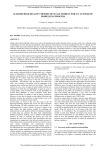
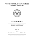
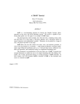
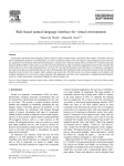
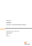
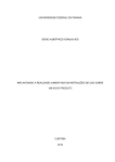
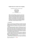
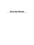
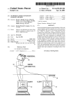
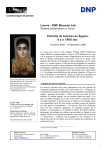
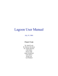
Thermal Touch: Thermography-Enabled Everywhere Touch Interfaces
for Mobile Augmented Reality Applications
Daniel Kurz∗
Metaio GmbH
(a)
(b)
(c)
infrared thermal image
infrared thermal image
infrared thermal image
Touch at (139.6, 32.1, 3.7)
(d)
(e)
(f)
(g)
Figure 1: We turn real objects into touch interfaces for Augmented Reality (a-c) by detecting residual heat at the touched surface on the object
using an infrared thermographic camera (d-f). Arbitrary surfaces become touch interfaces by augmenting spray-on graphical user interfaces (g).
A BSTRACT
1
We present an approach that makes any real object a true touch interface for mobile Augmented Reality applications. Using infrared
thermography, we detect residual heat resulting from a warm fingertip touching the colder surface of an object. This approach can
clearly distinguish if a surface has actually been touched, or if a
finger only approached it without any physical contact, and hence
significantly less heat transfer. Once a touch has been detected in
the thermal image, we determine the corresponding 3D position on
the touched object based on visual object tracking using a visible
light camera. Finally the 3D position of the touch is used by human
machine interfaces for Augmented Reality providing natural means
to interact with real and virtual objects.
The emergence of wearable computers and head-mounted displays desires for alternatives to a touch screen, which is the primary user interface in handheld Augmented Reality applications.
Voice control and touchpads provide a useful alternative to interact
with wearables for certain tasks, but particularly common interaction tasks in Augmented Reality require to accurately select or define 3D points on real surfaces. We propose to enable this kind of
interaction by simply touching the respective surface with a fingertip. Based on tests with a variety of different materials and different
users, we show that our method enables intuitive interaction for mobile Augmented Reality with most common objects.
The concept of Augmented Reality (AR) involves more than rendering virtual objects overlaid onto reality. Being a user interface,
AR should also allow for interaction of the user with both virtual
and real objects. The most commonly used type of Augmented Reality is video see-through AR, where both virtual information and
a (real-time) image of a real object or environment are shown on a
display. On handheld devices, such as smartphones and tablet PCs,
the displays are usually touch screens. As a result, the majority
of user input and user interaction in handheld AR is realized using
these touch screens. Interaction elements, such as buttons or sliders,
can be either attached to the screen coordinate system or they can
be attached to the coordinate system of any real object, if the pose
of the object relative to the camera is known. Such elements can
then for example be used to change the state, position, color, or size
of virtual objects. Another common approach to manipulate the
position, orientation, or size of virtual objects is based on touching
them on the screen. While dragging an object on the screen might
change its position in 3D, multi-touch gestures, such as pinching,
might change the scale.
In any case, these user interfaces are not always natural and intuitive because the user physically interacts with a screen (in 2D)
instead of interacting with an actual real object or environment (in
3D). Another reason to consider alternatives to touch screen-based
user interfaces for Augmented Reality is the fact that wearable computers and lightweight HMDs become increasingly important, and
they often do not have a touch screen. This raises the need for novel
means to interact with real objects and digital information associated with them in Augmented Reality applications.
Probably the most natural way for humans to interact with an
object is to touch it with their hands. This is also frequently used
in AR to change the viewpoint of a camera towards a real object.
Translating or rotating real objects enables exploration of virtual
objects attached to them from different perspectives and therefore
is a fundamental part of interaction in AR. In this paper, however,
Index Terms:
H.5.2 [User Interfaces]: Input devices and
strategies—Graphical user interfaces; H.5.1 [Multimedia Information Systems]: Artificial, augmented, and virtual realities—
Evaluation/methodology
∗ e-mail:
[email protected]
I NTRODUCTION
we are interested in interaction tasks that require the selection of a
certain point in 3D space, or more precisely: on the surface of a
real object. Example use cases include triggering virtual buttons or
sliders attached to real objects, placing virtual items or characters
in an environment for gaming, or marking defects on an object in
a maintenance scenario, so a worker can localize and fix them later
on. We aim at enabling this by simply touching the surface of a real
object at a desired position with a fingertip.
This paper proposes to use infrared thermography, which provides the pixel-wise temperature of the captured environment, in
combination with a visible light camera to turn any real object into
a touch interface. The visible light camera is used to keep track of
the position and orientation of the object while the thermal camera
allows for detecting touches. We do so by determining the thermal
energy a surface of an object emits after it has been touched (and
thereby heated up locally) by a fingertip. While infrared thermal
cameras are currently expensive, they will become affordable and
ubiquitous in handheld devices as well as wearable computers in
future, which makes the proposed method widely applicable.
2
R ELATED W ORK
Interaction in Augmented Reality is a wide and widely studied field,
and this section will particularly focus on human computer interfaces that involve hands in free space or interaction of hands with
physical uninstrumented surfaces.
Hand pose estimation, tracking, and gesture recognition has been
frequently used for interaction with augmented desktop systems, in
which a video projector displays digital information on a static and
planar surface. A variety of approaches to hand tracking are based
on instrumenting the hand or fingertips, e.g. using gloves [15].
However, it is clearly more desirable to interact with bare hands.
There is a whole body of work focused on detecting and tracking
hands based on visible light cameras [1], e.g. by skin color matching. These approaches are sensitive to illumination, which is a severe limitation not only in video projector-based setups but also for
mobile applications that need to work anywhere. One illuminationinvariant approach to track bare hands and fingertips for projectorbased augmented desk interfaces [14, 11] uses thermal imaging to
segment the warmer hands from the colder background.
In fact, in this paper, we are not aiming at detecting and tracking hands or fingertips, but we intend to reliably detect and localize
touches between a fingertip and a real object or surface. This enables different kinds of interaction techniques which are based on
defining 3D positions on the surfaces of real objects. For distant
objects, e.g. walls, laser pointers can be used to point at a desired
position on a surface, which can then be detected and localized by
a camera, e.g. [7]. For real objects within reach, using the fingers
appears to be the most natural and intuitive way for this task.
There are different approaches that try to detect fingers touching real objects, without instrumenting the hand or the objects.
Occlusion-based methods, e.g. [9], detect if a certain area of a real
object is occluded (by a hand) from the view of a camera and handle
this case as if the area was touched. These methods, however cannot
distinguish between occlusions and touches and thereby put heavy
constraints on user interfaces. For example, considering a number
pad as shown in figure 1 (g), it is impossible with occlusion-based
approaches to trigger the button 5 without triggering at least one of
the surrounding buttons beforehand.
Another method to detect touches uses a depth sensing camera
to determine if fingers approach a real surface or object [17]. When
mounted to a shoulder and combined with a wearable video projector, user interfaces may be projected onto arbitrary surfaces, including the user’s hands and arms [2]. While the method can clearly distinguish between a finger occluding an object at a distance of many
centimeters from a finger touching the object, this distinction is not
reliable if the finger is less than 2 cm apart from the surface due
Infrared thermal camera
Visible light camera
Custom mount
Tablet computer
Figure 2: The hardware prototype used throughout this paper comprises a visible light camera and an infrared thermographic camera
attached and connected to a tablet computer with a custom mount.
to noise in the depth image. Furthermore, the pursued method is
sensitive to approach angle and requires fingers to be outstretched
for proper detection. Additionally, assumptions are used, such as
that the left-most point of a finger is the fingertip, which work for
their shoulder-mounted setup, but are not generally applicable. Another approach to determine a finger touching a surface is based on
detecting the pressure applied to the fingertip. Different pressures
result in visibly distinct patterns of blood volume or perfusion beneath the fingernail, which can be imaged and classified [10]. This
approach does not work with opaque nail polish.
The approach most similar to the method proposed in this paper has been used in the context of static projector-based table-top
setups. It attempts to localize touches between fingertips and uninstrumented (planar) surfaces by detecting the residual heat a touch
leaves on the surface, using a thermographic camera [8, 6]. After calibration of the static setup, the approach proposed by Larson
et al. [8] performs background subtraction in the thermal image
followed by a segmentation of hands and localization of fingertips
based on this segmentation. In the next step, a classifier determines
for all pixels that were in the vicinity of detected fingertips in the
current or recent frames, if the pixel captures residual heat as a result of a touch or not. The employed classifier is based on smoothed
temperature, temporal derivative of temperature, and backgroundsubtracted temperature. Finally the method fits geometric primitives, such as lines, into the pixels classified as touched pixels accumulated over a number of frames.
A similar approach has been proposed by Iwai and Sato [6] to select magazines from a static scene by touching them with the hand.
Selected magazines can then be made transparent in a projective
table-top setup. Their touch detection method is also based on background subtraction in a thermal image and additionally considers
the camera image of a visible light camera. This helps distinguishing between touches (where only the thermal image differs from
the background image) and occlusions (where both the thermal image and the visible image differ from the background image). The
fact that the methods proposed in [8] and [6] heavily make use of
temperature samples of the same point at different points in time,
makes it challenging for dynamic or mobile setups where both the
object to interact with and the camera may freely move.
This paper looks into how this fundamental approach can be extended to be used in mobile AR applications dealing with freely
moving 3D objects. Thereby the position of a touch needs to be
determined in the 3D object coordinate system and user interfaces
based on our proposed method may have a spatial relationship to
the real 3D object. For example, such user interfaces may take advantage of existing haptic features on the surface of an object, such
as proposed in [3]. An example for such interfaces is shown in figure 1 (a-c), where touching the headlight of a miniature car causes
an Augmented Reality application to visualize how the headlight
looks when turned on. We believe that thermography-based interaction techniques, e.g. for image creation [5], will gain more attention in the near future not only because the hardware becomes
available at low cost. Most importantly it provides unique and interesting properties, such as capturing residual heat, and beyond,
e.g. capturing thermal reflection [13].
3 P ROTOTYPE , C ALIBRATION AND R EGISTRATION
We built a handheld hardware prototype including a thermal camera
and we developed a software prototype to evaluate our method and
to implement demonstrations. In the following, we describe the
hardware prototype and its calibration, as well as the object tracking
framework we use, and which data it requires.
3.1 Hardware Prototype and Calibration
Our experimental setup uses an optris PI 200 camera connected to a
handheld tablet computer, as shown in figure 2. The camera rigidly
combines a visible light camera, which provides RGB images at a
resolution of (480 × 360) pixels, and an infrared camera providing
thermal images at a resolution of (160 × 120) pixels. While the
camera provides a larger temperature range and temperature resolution, our implementation uses temperatures discretized to a byte
corresponding to a range of 25◦ C. The thermal images are corrected
for radial distortions by the camera’s driver. Therefore our methods
and all steps described in the following are performed on undistorted thermal images.
The intrinsic parameters of the visible light camera (Kv ) and the
thermal camera (Kt ) as well as the 6DoF rigid body transformation between the two cameras (t Tv ) have been calibrated offline.
For calibration, we built a checkerboard-like pattern that can be observed in both cameras, similarly as in [16]. This pattern enables
gathering 2D-2D correspondences between the image of the visible light camera and the image of the thermal camera. We cut out
squares from a piece of bright cardboard. When attaching the cardboard to a warm and dark object, such as an LCD screen in our
case, the squarish holes in the cardboard will appear dark for the
visible light camera because of the black LCD screen. They appear as warm squares in the infrared image, because the (turned on)
LCD screen is warmer than the the cardboard. The 2D positions of
the square corners were determined for a set of image pairs of both
cameras taken from different viewpoints, as exemplarily shown in
figure 3. This allows to calibrate the intrinsic parameters of both
cameras individually using Zhang’s method [18] and consequently
for determining the 6DoF rigid body transformation (t Tv ) between
the two cameras. Figure 4 illustrates the involved coordinate systems.
The prototype was built due to the lack of suited devices being
available off the shelf. In the near future, consumer handheld devices will be equipped with infrared thermal cameras and visible
light cameras and therefore provide a comparable hardware setup
at a more attractive form factor and price. Our method will be
even more relevant in practice once wearable computers and headmounted displays, that do not include a touch screen for interaction,
are equipped with low-cost thermographic cameras.
3.2 Object Tracking and Required Models
As described above, we aim to detect the position of a touch not
in a 2D image coordinate system but in the 3D coordinate system
of a real object (or environment). This requires knowledge of the
transformation of the real object relative to the camera.
We use a natural feature-based object tracker, which is part of
the Metaio SDK1 , to determine the position and orientation of an
1 http://www.metaio.com/sdk
Figure 3: The checkerboard-like pattern we use to calibrate the visible light camera (left) and the infrared thermal camera (right).
object relative to the visible light camera in real-time. For planar
objects, the required tracking model of an object is a fronto-parallel
image while for general 3D objects either a map of 3D points with
associated feature descriptors or a 3D edge model can be employed.
We use and consider the object tracking framework as a black box
which takes a (visible light) camera image and a tracking model as
input and provides the 6DoF pose v To of the object in the coordinate system of the visible light camera.
For each object, our proposed method additionally requires a
model of the touchable surfaces of the object, which is parametrized
as a triangle mesh in our implementation. This surface model is not
used for object tracking but is only needed to determine the position of a touch on the object. The accuracy and level of detail of
the surface model controls the accuracy of the resulting touch position. Planar rectangular objects, which are commonly used in AR
applications, can be fully described with only two triangles.
4
TOUCH D ETECTION
Our approach to detecting the touch between a fingertip and a real
object requires solving two problems. Firstly, we need to detect
such a touch in the thermal image, and the second problem is to
determine the corresponding 3D position in the object coordinate
system. We first have a look at the temperature profiles of surface
points in case they are touched, occluded, or not interacted with.
4.1
Temperature Profiles for Different Cases
Over a sequence of consecutive images, a surface point captured in
the thermal image might reveal the following temperature profiles.
Object Only: The measured temperature remains relatively
constant at the temperature of the object, when only imaging the
object throughout a sequence.
Hand Only: While imaging the hand, the temperature measured in a pixel corresponds to that of a hand and only changes
moderately over time.
Occlusion by Hand: When imaging the object and then a hand
occluding the object, a sample in the thermal image will first represent the temperature of the object. Then, after occlusion, it will immediately and rapidly change to the temperature of the hand. Once
the occluding hand leaves the sample, its temperature again rapidly
changes to the object temperature.
Touch by Hand: A sample in the thermal image capturing a
touch between a hand (e.g. finger tip) and an object, first measures
the temperature of the object, followed by a rapid change to the
temperature of the hand once the finger occludes the object. While
touching the object, the finger keeps occluding the touched surface
of the object and the measured temperature remains relatively constant. Once the finger is released, the temperature of the sample
point will rapidly decrease to a temperature between the temperature of the hand and the temperature of the object. It will then
smoothly converge back to the initial temperature of the object.
4.2 Touch Detection in the Thermal Image
The methods proposed in [6] and [8] to detect residual heat resulting from a touch between a hand and a surface in a thermal image
are designed and well-suited for projective table-top setups, where
the thermal camera is static with respect to the (planar) surface,
i.e. real object. Particularly the approach described in [8] includes
smoothing the thermal image over time, background calibration,
combining segmentations from subsequent images, and temporal
derivatives of temperature, which all require temperature samples
of the same surface points at different points in time. In their static
setup, these samples simply correspond to a single static pixel position in the thermal image.
In our dynamic setup, where both the camera and the object may
move, object tracking, as explained in section 3.2, provides the pose
of the object relative to the visible light camera. By concatenating
this transformation with the calibration between the two cameras
as explained in section 3.1 we are able to sample a 3D point on
the surface of the object in the thermal image during motion. Due
to unpreventable small inaccuracies both in the pose provided by
the object tracking and in the calibrated transformation between the
two images, collected temperature samples, however, will not correspond to the same point (or area) on the surface but represent
different points scattered around the intended sample position. Another challenge here is that thermal and visible light images are not
perfectly synchronized.
Furthermore the approach of [8] uses a classifier to determine for
every pixel the probability that the pixel captures residual heat. The
per-pixel result may include residual heat of any shape and size and
can then be further processed, e.g. by fitting lines to it for strokebased interaction. In contrast, we are only interested in detecting a
single touch by a fingertip.
We propose an approach to detect the residual heat caused by a
touch between a fingertip and a real object that is based on a single
thermal image and utilizes object tracking to constrain detection
to warm areas of a certain physical size and shape on the surface,
which corresponds to the size of a fingerprint. Our approach is
designed such that it works with different materials having different
thermal conductivity and such that it is invariant to the temperature
of the touched object. Our description of what to search for is based
on three assumptions about a touched surface area:
• Its temperature is lower than that of a hand and higher than
that of the object.
• Its shape is reasonably circular.
• Its physical area corresponds to that of a fingerprint.
Our proposed method starts by determining the minimal temperature tmin and the maximal temperature tmax which is captured in at
least 5 pixels of the thermal image. Our assumption is now, that tmax
corresponds to the temperature of the hand while tmin corresponds
to that of the object. If no hand is present in the camera image, the
two determined temperatures will be more similar to each other and
the following steps shall not detect any touches.
According to section 4.1, pixels imaging residual heat as a result of a touch should now have a temperature significantly lower
than tmax and higher than tmin . Particularly we are interested in a
connected circular region of pixels in the desired temperature range
that has an area similar to that of a fingerprint. Note that given
the pose (at physical scale) obtained from object tracking, we are
capable of converting any physical distance on the object into the
corresponding pixel distance in the thermal image.
We use OpenCV’s SimpleBlobDetector [4] to localize bright circular blobs in the thermal image. The detector is based on binarization of the image and we constrain the thresholds used for binarization to an intensity (i.e. temperature) range of [t1 ,t2 ] and require that detected blobs should have an area in the interval [a1 , a2 ],
Po
v
(a)
pt
To
(b)
Kv
Kt
(c)
Tv
t
Figure 4: Illustration of the involved coordinate systems and resources: a visible light camera image (a), a thermal camera image
(b) and a model of the real object to interact with (c).
which corresponds to the size of residual heat resulting from a fingertip touching a colder surface. The parameters we use were found
experimentally and are as follows.
t1 = (1 −
1
1
)tmin + tmax
16
16
a1 = 0.32 cm2
3
3
t2 = (1 − )tmin + tmax
8
8
a2 = 1.54 cm2
The blob detector then returns a set of circular regions (blobs)
with their respective positions in the thermal camera image. We exclude blobs with a center closer than 10 pixels to the image boundaries, because fingers entering and leaving the image may result in
false positive detections in these regions. Because we are interested
in detecting a single touch, we also reject all detected blobs in case
more than one has been detected in a single image.
The touch position pt in the coordinate system of the thermal
image (cf. figure 4 (b)) is defined as the center of the remaining detected blob (if any). This position then needs to be transformed to
the coordinate system of the real object resulting in the 3D position
of the touch Po . This finally enables natural interactions with the
real object and virtual information attached to it as will be elaborated with different examples in section 6.
4.3
Determining the 3D Touch Position
Given the 2D position of a detected touch pt in the thermal image,
we make use of the object tracker explained in section 3.2 to determine the corresponding 3D position Po on the surface of the real
object. The object tracker takes the visible light image (figure 4 (a))
and a tracking model of the real object to determine the 6DoF rigid
body transformation v To from the object coordinate system to the
coordinate system of the visible light camera. Concatenating this
transformation with the calibrated transformation t Tv from the coordinate system of the visible light camera to the thermal camera
results in the transform t To from object coordinate system to the
thermal camera’s coordinates.
To determine the 3D position of the touch in the coordinate system of the object, we intersect a ray from the origin of the thermal camera transformed to the object coordinate system piercing
through pt to find the first (3D) intersection of the ray with the surface model (figure 4 (c)) of the object. If such intersection exists,
then it corresponds to the three-dimensional position of the touch
Po and can serve as input to any Augmented Reality user interface.
Figure 5: Different materials used in our evaluation: paper on a plastic table top (0), ceramic (1), rigid PVC (2), foam plastic (3), cardboard (4),
laminated fiber sheet (5), glass (6), thin plastic (7), steel (8), multi-layer board (9).
5 T EST DATASET AND E VALUATION
The approach described in the previous section is designed to cope
with objects of different materials and at different temperatures. It
should also work for different users that might have different finger
temperatures and their touches may differ in terms of dwell time
and pressure. To evaluate how well our proposed touch detection
algorithm works in realistic situations, we created a test database of
infrared thermal image sequences of different people touching the
surfaces of different materials at different temperatures.
5.1 Ground Truth Test Dataset Acquisition
The setup and the objects acting as material samples to acquire a
test dataset are shown in figure 5. The material samples include paper, plastics, glass, and metal, and they were placed on a table such
that they are centered with the camera, which has been attached to
a tripod at a distance of about 300 mm from the table top.
Four subjects performed the test in an office environment with an
air temperature of about 25◦ C, while another group of four subjects
performed the test outdoors at an air temperature of about 12◦ C.
All material samples were kept in the respective test environment
for at least half an hour before starting test runs to make sure their
temperature adapts to the air temperature.
Each subject was instructed to wait for an audio signal indicating
that capturing starts and then perform an action. For each material
the first action to be performed was moving the hand over the material sample without touching it. In the second run, the subjects
were asked to press the material sample at the center as if it was a
physical keyboard button. There were no instructions on which finger or which hand to use and the subjects could freely choose how
to approach and leave the object.
For all subjects, materials, and actions, we save sequences of 400
infrared thermal images at a frame rate of 96 Hz with corresponding
timestamps to disk and label them according to subject, material,
and performed action. For each sequence, we furthermore manually
label ground truth, i.e. the position of the center of the touch in the
coordinate system of the thermal image and the point in time when
the touch ended, i.e. the finger stops touching the object. An ideal
touch detector would not only provide an accurate touch position,
but also report a touch immediately after it happened with as little
delay as possible.
Figure 6 shows single images from the recorded sequences of six
different people touching material 0 in the office environment. As
can be seen in figure 6 (e,f), two people had fingertips that were
not significantly warmer than the object or even colder. While this
is something to keep in mind for future work, we excluded the sequences of these two people from all further analysis and they are
not part of the 8 subjects that contributed to the test dataset.
(a)
(b)
(c)
(d)
(e)
(f)
Figure 6: For most subjects, a warm fingertip leaves a warm fingerprint at the touched object (a-d). However, some subjects have
a fingertip temperature similar to the air temperature of 25◦ C (e) or
even below that temperature, leaving a cold fingerprint (f).
5.2 Evaluation and Results
It is crucial for the usability of any interaction method that it works
as the user expects it to work. In the context of our approach to
detect touches, it is very important that there are few false positives
(i.e. touch detection even though no touch occurred). Furthermore,
it is important to achieve a high rate of true positives, i.e. that actual
touches are being detected.
In the following, we first evaluate how our proposed method performs in this respect on the test dataset described above. We then
evaluate the accuracy of our proposed method. The question of
which kinds of interaction this method can be used for strongly depends on the accuracy of the determined touch position. While triggering buttons or selecting parts of an object only requires accuracy
to the size of the button or part, positioning of virtual objects in the
real environment or slider interfaces require a higher accuracy.
5.2.1 Evaluation on the Test Dataset
We exclude all sequences of material sample 8, i.e. steel, from further evaluation simply because our method does not work at all for
this material. Due to its high thermal conductivity, residual heat
disperses very fast within the material making it impossible to detect it using our method. All remaining sequences are loaded from
files and each frame is processed individually by our touch detection method described in section 4.2. We consider a detected touch
correct (i.e. a true positive) if it occurred after the manually labeled
ground truth point in time when the finger is released from the surface, and if the detected position differs from the labeled ground
truth position by not more than 5 pixels.
40
Table 1: Evaluation results: true positive (TP) and false positive (FP)
touch detections on the test dataset with different materials (Mat.).
20
1
100
0
2
100
0
3
75
0
4
100
0
5
100
0
Average error: 1.995 px
Sequences without a touch
Mat.
FP[%]
0
0
1
2
12.5 0
3
25
6
50
25
7
9
87.5 100
0
0
all
90.3
2.8
Average delay: 0.190 s
10
Detected touch position in millimeters
Sequences with a touch
Mat.
0
TP[%] 100
FP[%] 0
30
0
-10
4
5
37.5 0
6
0
7
25
9
all
12.5 12.5
-20
-30
-40
The results for the dataset excluding material 8 (steel), leaving
144 sequences of 8 subjects and 9 materials, can be found in table 5.2.1. For the 72 sequences with a touch, the touch could be
correctly detected in 65 sequences, which corresponds to 90.3%. A
touch at a wrong position was found in 2 sequences (5.56%) which
both show material 6 (glass) in the outdoor environment. In these
sequences the attached circular sticker for numbering the materials
is erroneously detected, because it appeares warmer than the glass,
which reflects the cold sky. In 7 sequences our method could not
detect the touch. In these sequences, the contact between the finger
and the object is relatively short and therefore insufficient thermal
energy is transferred. The average delay between finishing a touch
and its detection is less than 200 ms and therefore sufficient for
many tasks that do not require immediate response.
The number of false positives within the sequences without a
touch is relatively high at 9 of the 72 sequences (12.5%). These
false positive detections find actual heat blobs in the thermal image, which are due to touches that happened before the sequence
starts, e.g. while placing and arranging the material sample under
the camera. This shows a problem which could be solved by background subtraction as proposed in [6, 8] or other means that are
better suited for dynamic scenes and mobile applications in future.
5.2.2
Accuracy and Precision in Object Coordinates
As given in table 5.2.1, we computed the error of the detected position with respect to ground truth, which is slightly below 2 pixels on
average. This measure is however not very meaningful firstly because the ground truth position is not clearly defined and has been
manually labeled. Secondly, this value corresponds to the error in
the image, whereas it is most important how the accuracy of our
method is in the coordinate system of the object including the impact of inaccuracy of the user, inaccuracy of the object tracking,
and inaccuracy of the calibration.
To evaluate the relevant accuracy in a realistic setup, we used
the application shown in figure 1 (right), which places ten buttons
corresponding to all digits on a tracked surface and enables touching them. All buttons have a size of (25 × 25) mm and there is no
spacing between them. In this case we used a predetermined planar
object with a predetermined tracking model at a known physical
size as the surface to interact with. We store the positions at which
touches were detected for 10 runs, where in every run each button
was touched once in a predefined order with the index finger of the
left hand approaching from the bottom left. The resulting positions
are plotted in figure 7 together with large black crosses which indicate the centers of the buttons. We observe an average error of
7.81 mm where the smallest error over all 100 touches is 0.95 mm
and the largest error is 11.98 mm. As can be seen from figure 7, the
detected touch positions corresponding to a particular button are inaccurate (i.e. not centered around the correct position) but they are
relatively precise (i.e. they are clustered). The standard deviations
within the touches of the individual buttons are all less than 3.5 mm.
-50
-60
-40
1
6
-30
-20
-10
0
10
20
30
Touched key on Spray-On GUI number pad
2
3
4
7
8
9
40
5
0
Figure 7: Positions of detected touches when typing numbers on a
virtual number pad using our proposed method. The centers of all
buttons are shown as black crosses.
The observed error distribution suggest that there is a systematic error, which most likely results from inaccuracies in the intrinsic and extrinsic parameters of the thermographic camera and
therefore can be accounted for with an improved calibration procedure. Nevertheless the achieved accuracy is sufficient to select
(square) buttons at an interval of 25 mm. This is not significantly
more than the distance between the keys of a traditional QWERTZ
keyboard, which is 19 mm for many commonly used models. As
will be elaborated in section 6, many applications do not require
millimeter-precise positional input and therefore can benefit from
our proposed method right away.
The accuracy of detected touches has been evaluated for planar
objects only, but we assume that our method provides similar results
for generic 3D objects given that the thermal camera captures the
touched surface more or less orthogonally to the optical axis. The
reason is that our method does not distinguish between planar and
non-planar objects.
Note that this experiment not only measures how accurate our
touch detection works but also the capability of users to accurately
touch given points with their fingertip.
6 P OTENTIAL A PPLICATION F IELDS
There are many potential applications for our proposed method to
turn virtually any real object into a touch interface in the context
of Augmented Reality. The supplementary video showcases prototype implementations of three ways how AR applications can take
advantage of our method. While the hardware prototype we use
is based on a tablet PC and therefore handheld (see figure 2), the
application fields are mainly targeted towards wearable computers
and head-mounted displays where no touch screen is available.
The software prototypes run on the Windows 8 operating system
and are based on the Metaio SDK, which is an Augmented Reality software development kit combining the object tracking functionality explained in section 3.2 with the capability of creating a
3D scene of virtual objects and displaying the scene overlaid on
the live camera feed. The application examples either use arbitrary
surfaces to interact with or rely on specific and known planar or
three-dimensional objects, for which a tracking model exists.
(a)
(b)
Figure 9: Potential application of the proposed method: touching a
room on a printed floor plan is being detected and subsequently provides the user with digital and up-to-date information on the room.
(c)
(d)
Figure 8: Spray-on GUIs enable ad hoc manual input on any previously unknown nearby surface.
Spray-On GUIs Certain interaction tasks, such as typing in a
number, require a surface to type on, but it is not important which
surface it is. No matter if the user is at home or on the go, any
nearby surface, such as a wall or a table top, can be used for interaction. If virtual buttons are sprayed onto a surface the position of
these button in the coordinate system of the object which includes
the surface is arbitrary.
We therefore use so called instant tracking, which creates a reference image of the object to track on the fly while virtually spraying the GUI, see figure 8 (a,b). While this is currently triggered
by tapping on the screen, it could be solved for example using
voice input for wearable computers. Once the number pad has been
sprayed on the surface, it sticks to the surface while the camera may
freely move around. After one of the sprayed-on buttons has been
touched on the physical surface (figure 8 (c)), the touch is detected
in the thermal image and its position in the coordinate system of
the numpad is determined. This position is finally mapped to the
corresponding pressed number, as shown in figure 8 (d).
In fact there are some limitations in the current prototype: firstly
the surface to interact with needs to be planar and have some texture
such that the visual object tracker may keep track of it. Secondly,
we use an assumption on the physical size of the surface corresponding to the on-the-fly reference image used for tracking and
we assume the camera’s optical axis is perpendicular to the surface
at the time the reference image is taken. Because the thermal and
the visual camera do not share the same optics, they have a baseline
and consequently require tracking in real scale. However, our assumptions can be easily replaced by measurements of the physical
scale and orientation of the surface in a hardware setup including a
depth sensing camera in the future.
Augmented Floor Plans Printed floor plans usually only contain brief information on each room. By simply touching a room
on a floor plan of a shopping mall, our prototype in figure 9 provides detailed digital information on the corresponding shop, such
as opening hours, and contact information. As opposed to printed
information, the augmented information can always be up-to-date
and potentially user-generated (i.e. customer reviews).
In this use case, there is no need to render any virtual buttons
or GUI registered with the floorplan, but we use existing printed
shapes of the floor plan as buttons instead. Therefore, object tracking needs to be performed in a known coordinate system and consequently requires an a priori tracking model of the real object, which
in this case is a fronto-parallel image.
Augmented Reality User Manuals The functionality of certain parts of a product may be explained in an intuitive fashion by
means of Augmented Reality user manuals. To this end, such manuals overlay spatially registered 3D information on top of a view of
the real object. However, similarly as for classical printed manuals,
the user needs to define which part of an object (i.e. product) he or
she is interested in. This could be implemented by selecting a part
from a list of parts, but a much more intuitive interface would allow
the user to simply use their fingers to touch the part of the object
they would like to learn about.
As is shown in figure 1 (a-c), we implemented a prototype based
on a physical miniature model of a car. When the user for example
touches one of the headlights, the Augmented Reality visualization
will explain their function and what they look like when turned on.
Similarly, touching the engine hood results in a visual explanation
how it can be opened, e.g. to refill the brake fluid. Such kind of
interfaces could be handy in the context of electronic devices, such
as printers, or physical aids, such as stair lifts or walkers, where
touching a button or a thumbscrew would start an Augmented Reality user manual explaining the function of the respective part.
In this use case, a tracking model (we use an edge model) of the
real object is crucial because detected touches need to be mapped
to a known object coordinate system related to the car. Furthermore
the surface model is more complex than a simple plane in this application. Selectable parts could be highlighted on the car, but it is
not mandatory to do so because the real object itself provides features for the user to identify. The reader is advised to consult the
supplementary video which best explains the described application.
Further Applications There are more possibilities to take advantage of our proposed method that are not covered in the video.
A printed map, as for example found frequently in train stations or
bus stops, could serve as user interface for (pedestrian) navigation
applications running on wearable computers. By simply touching
the destination on the map with a finger, our method enables providing the corresponding absolute and global position to a routing
software that would then determine the best route to this destination
and provide navigation instructions on the way.
Augmented Reality has the power to change the way we play
video games. If a game does not take place in a virtual reality anymore but in the environment around a user, e.g. a living room, appropriate ways to interact with the environment are needed. Tasks
such as placing game characters in the environment or collecting
virtual goods could be implemented in an intuitive fashion using
our proposed method by simply touching the according surfaces.
We also think that particularly industrial applications could benefit from natural and tangible touch interaction, when for example
a quality assurance engineer can mark the position of defects on a
physical product simply by touching them. Maintenance staff could
then review them in an AR view and fix the defects afterwards.
7
C ONCLUSIONS AND F UTURE W ORK
This paper presented an approach to turn the surfaces of real objects into true touch interfaces by detecting the radiation of the
warm fingerprint a touch leaves on the surface using a single infrared thermal image. We showed that our approach works with
objects from a variety of different materials and that our method is
adaptive to the temperature of the object, which may move unconstrained. At the example of several potential applications and use
cases, which were implemented as prototypes, we showed how our
proposed method can provide very intuitive and useful user interfaces for mobile Augmented Reality applications. Particularly the
upcoming pervasiveness of wearable computers and head-mounted
displays requires novel means to interact with real environments
and digital information related to it, without using a touch screen.
Our proposed method has limitations, particularly resulting from
the fact that we detect the touched surface after it has been touched.
Firstly, this approach inherently introduces a delay between a touch
and the time it can be detected. In our experiments, we found the
delay between the finger releasing the object and the detection to be
0.191 s on average. Our approach also requires the user to touch the
surface for a longer period of time than the case for regular touch
screens or approaches such as OmniTouch [2]. However, in our
user tests, where the subjects did not receive any instructions how
long to touch the surface, the vast majority of touches lasted long
enough to cause a detectable residual heat. Furthermore our approach requires the touched surface to be visible (i.e. not occluded)
for the thermal camera after the touch. This did not cause any problems in the tests, but it might become problematic when performing
subsequent touches between which the user does not move the hand
away so the touches gets detected. Our tests revealed that our current approach cannot handle touches by all users on all surfaces.
Particularly users with cold fingers and surfaces with high thermal
conductivity impose difficulties. When using our method over a
longer period of time, the surface may also wick away heat from
the finger, which may require a break before the user can continue.
However, there are clear advantages of our method over those
described in previous work. Our approach allows for truly distinguishing touches from occlusions in a dynamic and mobile setup
interacting with arbitrary three-dimensional objects. While our current implementation requires touched surface to be locally reasonably planar and parallel to the image plane to ensure circularity of
the detected blob, surfaces that are not parallel to the image plane
can be dealt with based on information from the object tracking.
One could first detect blobs without any constraint on their circularity, then rectify the thermal image for all of them based on their
average 3D position and 3D normal obtained from the registered
surface model, and finally run a cicular blob detector on the rectified images. Because our approach does not aim at detecting a
hand, there are no constraints on the approach angle of fingers or if
they are outstretched or not. In fact, the actual touch we detect afterwards may even take place occluded from the thermal camera or
outside its frustum, which largely increases the interaction volume.
In future work we will look into approaches that also detect
touches caused by users with cold fingertips. Another issue for further research is that residual heat remains detectable for a long time
after the touch for certain materials. We will explore approaches
to suppress recurring detections of such touches while at the same
time enabling to correctly detect new touches at the same position.
We will also investigate how the visible light camera in our setup,
or potentially an additional depth-sensing camera, may further aid
our thermography touch detection approach beyond what has been
presented in [12] and [6].
Generalizing our method will support dealing with more than
one touch at a time, where multiple touches may be caused by
the same hand, or different hands. As opposed to classical touch
screens, imaging the hands enables assigning touches to the corre-
sponding hand, enabling advanced interactions. The position of a
touch projected into the visible light camera image may further add
degrees of freedom to the 3D position of a touch, e.g. by handling
touches in the left side of the image as left mouse button clicks and
those in the right side as right mouse button clicks. There are many
more ways to combine our proposed method for natural touch interfaces with more modalities, e.g. speech input, in the future.
ACKNOWLEDGEMENTS
This work was supported in part by the project “PASSAge” by the
German Federal Ministry of Education and Research (BMBF), reference number 16SV5745. This work was also partially supported
by the ENIAC Joint Undertaking “MIRTIC”, reference number
NA 304653 and the Bayerisches Staatsministerium für Wirtschaft,
Infrastruktur, Verkehr und Technologie under reference number
IUK401/001. We further wish to thank Darko Stanimirovic for his
help as well as all subjects who contributed to the test dataset.
R EFERENCES
[1] A. Erol, G. Bebis, M. Nicolescu, R. D. Boyle, and X. Twombly.
Vision-based hand pose estimation: A review. Computer Vision and
Image Understanding, 108(12):52 – 73, 2007.
[2] C. Harrison, H. Benko, and A. D. Wilson. Omnitouch: Wearable
multitouch interaction everywhere. In Proc. UIST, 2011.
[3] S. J. Henderson and S. Feiner. Opportunistic controls: Leveraging
natural affordances as tangible user interfaces for augmented reality.
In Proc. VRST. ACM, 2008.
[4] Itseez. OpenCV (Open Source Computer Vision), March 2014.
[5] D. Iwai and K. Sato. Heat sensation in image creation with thermal
vision. In Proc. ACM SIGCHI Int. Conf. on Advances in computer
entertainment technology, 2005.
[6] D. Iwai and K. Sato. Document search support by making physical
documents transparent in projection-based mixed reality. Virtual Reality, 15(2-3):147–160, June 2011.
[7] D. Kurz, F. Häntsch, M. Große, A. Schiewe, and O. Bimber. Laser
pointer tracking in projector-augmented architectural environments.
In Proc. ISMAR, 2007.
[8] E. Larson, G. Cohn, S. Gupta, X. Ren, B. Harrison, D. Fox, and S. Patel. Heatwave: Thermal imaging for surface user interaction. In Proc.
SIGCHI Conf. on Human Factors in Computing Systems, 2011.
[9] G. A. Lee, M. Billinghurst, and G. J. Kim. Occlusion Based Interaction Methods for Tangible Augmented Reality Environments. In Proc.
VRCAI, 2004.
[10] S. A. Mascaro. The common patterns of blood perfusion in the fingernail bed subject to fingertip touch force and finger posture. Haptics-e,
4:1–6, 2006.
[11] K. Oka, Y. Sato, and H. Koike. Real-time tracking of multiple fingertips and gesture recognition for augmented desk interface systems. In
Proc. Int. Conf. on Automatic Face and Gesture Recognition, 2002.
[12] E. Saba, E. Larson, and S. Patel. Dante vision: In-air and touch gesture sensing for natural surface interaction with combined depth and
thermal cameras. In Proc. Int. Conf. on Emerging Signal Processing
Applications (ESPA), 2012.
[13] A. Sahami, Y. Abdelrahman, N. Henze, S. Schneegas̈, M. Khalilbeigi,
and A. Schmidt. Exploiting thermal reflection for interactive systems.
In Proc. SIGCHI Conf. on Human Factors in Computing Systems,
2014.
[14] Y. Sato, Y. Kobayashi, and H. Koike. Fast tracking of hands and fingertips in infrared images for augmented desk interface. In Proc. Int.
Conf. on Automatic Face and Gesture Recognition, 2000.
[15] D. Sturman and D. Zeltzer. A survey of glove-based input. Computer
Graphics and Applications, IEEE, 14(1):30–39, Jan 1994.
[16] S. Vidas, P. Moghadam, and M. Bosse. 3D thermal mapping of building interiors using an RGB-D and thermal camera. In Proc. ICRA,
2013.
[17] A. D. Wilson. Using a depth camera as a touch sensor. In Proc. Int.
Conf. on Interactive Tabletops and Surfaces, 2010.
[18] Z. Zhang. A flexible new technique for camera calibration. Trans.
IEEE PAMI, 22:1330–1334, 2000.