1
 6. Once in TC mode, cycle
though the thermocouple
types to Type J by using the
Type/Units key.
7. Select Shift and Output (#7)
to source temperature. Key
in 0.0 °C and press Enter.
8. Select the mA, loop power,
and the HART option on
the isolated side. The mA
reading will be displayed
if all selections are made
correctly.
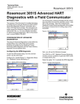
9. Connect a HART communicator or equivalent across
the 24 V dc power connections. Power on the device
and verify communication.
Save the transmitter configuration and perform an “As
Found” measurement before
making any changes to the
transmitter. This documents
the current state of the
transmitter.
10. Navigate to the Rosemount
Sensor calibration, lower
and upper trim methods.
A complete Menu Tree for
the Rosemount 3144 can be
found in the product reference manual.
11. Verify that the temperature unit of measure on the
7526A matches that of the
HART communicator.
12. Apply the Lower Trim point
or Offset by entering the
value requested by the
HART communicator. This is
typically a negative value.
Follow screen prompts and
proceed to the Upper Trim
point or Slope.
13. Apply the Upper Trim
point and follow screen
prompts to complete the A/D
calibration.
14. Verify the 4-20 mA output
meets published transmitter
specifications by performing
a D/A trim. Since the connections are already made,
simply follow the prompts
from the communicator and
verify the analog output on
the 7526A.
Get it done faster–quick tip
Save time when testing several transmitters that have the same
range by using the available nine preset output setpoints. They may
be recalled on an individual basis, or as an automatic up and down
cycle with configurable dwell time between each setpoint.
Automatic setpoint cycle setup:
1. Select the output mode desired. Example: TC OUT
2. Press the Shift Key and Autoset (#3 Key) to select the AUTOSET
function.
3. At the selection prompt for the sequence ending setpoint number
(AUTO SET POINT#), press the numeric key, 1-9, corresponding to
the final setpoint number of the sequence.
4. At the prompt “DWELL TIME”, “5-500?”, enter the number of
seconds (5 to 500) for the dwell time at each setpoint value, followed by the Enter key.
5. Press any other key to terminate the cycle.
Adding a Fluke 700
Series Pressure Module
To calibrate a pressure transmitter, the pressure measurement
capability needs to first be
configured for the 7526A. Follow
these steps:
1. Connect the Fluke 700 Series
Pressure Module as shown in
Figure 3.
2. Press the
pressure
key. The 7526A will sense
the pressure module
automatically.
Figure 3. Pressure module connection.
2 Fluke Calibration Multifunction calibration using the 7526A Precision Process Calibrator
3. Press the Type/Units key to
select desired units.
It is important to review the
recommended calibration procedure and tolerances required
by the manufacturer to ensure
the proper pressure module is
selected. The pressure transmitter used in this application note
is a simple gage unit that is referenced to atmospheric pressure.