1
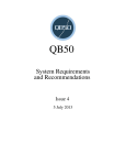
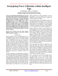
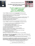
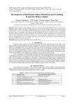
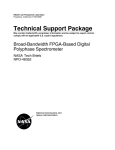
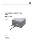
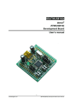
International Journal of Engineering Research in Electronics and Communication Engineering (IJERECE) Vol 1, Issue 5, April 2015 Home Automation using Lab VIEW [1] Rebecca Rajan,[2]Praveena Richu Jacob,[3]Priya Papechen,[4]Priya Antony,[5]Binu C. Pillai [1][2][3][4] UG Scholars, [5]Asst. Professor Department of Electronics & Communication Engineering, Amal Jyothi College of Engineering, Kanjirappally, Kottayam, Kerala, India. Abstract: Home automation is an application of ubiquitous computing in which the home environment is monitored by ambient intelligence. It leads to the concept of smart home. Smart home is a house that uses information technology to monitor the environment, control the electric appliances and communicates with the outer world with the help of data acquisition in LabVIEW software. It has an intelligent control over the activities performed frequently in daily life to achieve more comfortable and safety life. This system is based on the LabVIEW software which controls home and also act as a security guard of the home. It is a complex technology, at the same time it is developing. The system has temperature monitoring and controlling system, internal and external lighting systems and burglar alarm system to ensure family security. The system also has internet connection to monitor and control house equipments from anywhere in the world. It can send warning messages to the user as e-mail. The approach comprises of both hardware and software technologies. The aim of this project is to map the processes yielding optimal utilization of smart home technology, to ensure as many users as possible having access to the technology most relevant for their needs. Keywords: Smart home; LabVIEW; Data Acquisition Card; Automation. I. INTRODUCTION The demand for the home automation systems in homes and offices is increasing invariably. These systems directly work on the household appliances and provide effortless operation and control of the devices. In this paper, we have presented the concept of smart home using advanced graphical software called LabVIEW. It provides the programming tools to code power system applications more easily, which saves programming time. With the development of low cost electronic components, home automation migrated from being an industrial application to home application. The home automation, in our point of concern, deals with the control of home appliances from a central location [3]. A smart home is a space or a room which is provided with the ability to get accustomed by itself to certain situations to make the occupants feel comfortable and safe. This smart home control system provides security as well as a great level of flexibility and control for the building administrators and great comfort for the occupants. With the development of new electronic technologiesand their integration with older traditional building technologies, smart house is at last becoming a realpossibility. Possibly the first "home computer" was an experimental system in 1966. The Smart House Project was initiated in the early 1980’s as a project of the National Research Center of the National Association of Home Builders (NAHB) with the cooperation of a collection of major industrial partners. Smart House is not a new term for science society but is still far more away from people’s vision and audition [4]. This is because although recent various works has been done in designing the general overview of the possible remote access approaches for controlling devices, or in cases simulating the Smart House itself, and designing the main server, the design and implementation of an off-theshelf Smart House remote control application has been limited to simply the computer applications and just in cases mobile and web applications development. The "smart house" technology is one realization of home automation ideas using a specific set of technologies. It is a house that has highly advanced automatic systems for lighting, temperature control, security, control appliances, and many other functions. Coded signals are sent through the home's wiring to switches and outlets that are programmed to operate appliances and electronic devices in every part of the house. A smart home appears "intelligent" because its computer systems can monitor many aspects of daily living. As the number of controllable appliances in the home rises, the ability of these devices to interconnect and communicate with each other digitally becomes a useful and desirable feature. The consolidation of control or monitoring signals from appliances, fittings or basic services is an aim of home automation. Smart house technology can interface basically using computer interface. Smart house can also provide a remote interface to home appliances or the automation system itself, via telephone line, wireless transmission or the internet, to provide control and monitoring via a smart phone or web browser [1]. It can All Rights Reserved © 2015 IJERECE 55 International Journal of Engineering Research in Electronics and Communication Engineering (IJERECE) Vol 1, Issue 5, April 2015 send warning messages as an e-mail or SMS to the user. The system can also be controlled from anywhere in the world. This paper presents a smart home system that has two parts: Security system and Control system. The system has four subsystems. For security, burglar alarm system is provided. For control, three subsystems are provided. They are: Temperature control system, Internal lighting system, and External lighting system. These four subsystems are connected to the LabVIEW software as the main controller for these systems. Computer device that provided with LabVIEW software is the main controller unit for all systems in the house. It receives data from house sensors, process information and updates data for the difference systems, and transmit controlling signal to house systems and switching output devices. In addition, LabVIEW make the ability to monitor the important operations in the system to the users in order to be informed of the changes in the system. Users can also control the difference systems abilities, and chose the best system that required. Figure 1 shows the block diagram of the smart home designed in this paper. Fig. 1. Smart Home Block Diagram II. LABVIEW NI LabVIEW software is used for a wide variety of applications and industries. LabVIEW is a highly productive development environment for creating custom applications that interact with real-world data or signals in fields such as science and engineering. The net result of using a tool such as LabVIEW is that higher quality projects can be completed in less time with fewer people involved. So productivity is the key benefit, but that is a broad and general statement. LabVIEW is unique because it makes this wide variety of tools available in a single environment, ensuring that compatibility is as simple as drawing wires between functions. LabVIEW itself is a software development environment that contains numerous components, as shown in the figure 2 [1]. Fig. 2. LabVIEW Valuable Components A. G Programming Language The G programming language is central to LabVIEW so much, so that it is often called as “LabVIEW programming.” Using it, you can quickly tie together data acquisition, analysis, and logical operations and understand how data is being modified. From a technical standpoint, G is a graphical dataflow language in which nodes (operations or functions) operates on data as soon as it becomes available, rather than in the sequential line-by-line manner that most programming languages employ [7]. LabVIEW consists of two windows: Front panel and Block diagram. You lay out the “flow” of data through the application graphically with wires connecting the output of one node to the input of another. LabVIEW contains a powerful optimizing compiler that examines your block diagram and directly generates efficient machine code, avoiding the performance penalty associated with interpreted or cross-compiled languages. The compiler can also identify segments of code with no data dependencies (that is, no wires connecting them) and automatically split your application into multiple threads that can run in parallel on multi-core processors, yielding significantly faster analysis and more responsive control compared to a singlethreaded, sequential application [5]. B. Hardware Support LabVIEW Support for thousands of hardware devices, including: Scientific instruments, Data acquisition devices, Sensors, Cameras, Motors and actuators, Familiar programming model for all hardware devices, Portable code that supports several deployment targets. LabVIEW makes the process of integrating hardware much easier by using a consistent programming approach no matter what hardware you are using. The same initialize-configure-read/writeclose pattern is repeated for a wide variety of hardware devices, data is always returned in a format compatible with the analysis and reporting functions, and you are not forced to dig into instrument programming manuals to find lowlevel message and register-based communication protocols All Rights Reserved © 2015 IJERECE 56 International Journal of Engineering Research in Electronics and Communication Engineering (IJERECE) Vol 1, Issue 5, April 2015 unless you specifically need to. LabVIEW has freely available drivers for thousands of NI and third-party hardware [6]. In the rare case that a LabVIEW driver does not already exist, you have tools to create your own, reuse a DLL or other driver not related to LabVIEW, or use lowlevel communication mechanisms to operate hardware without a driver. C. UI Components and Reporting Tools Interactive controls such as graphs, gauges, and tables to view your acquired data. Tools to save data to file or databases, or automatically generate reports. Every LabVIEW block diagram also has an associated front panel, which is the user interface of your application. On the front panel you can place generic controls and indicators such as strings, numbers, and buttons or technical controls and indicators such as graphs, charts, tables, thermometers, dials, and scales. All LabVIEW controls and indicators are designed for engineering use [7]. Controls and indicators are customizable. You can add them either from a palette of controls on the front panel or by right-clicking on a data wire on the block diagram and selecting “Create Control” or “Create Indicator.” D. Technology Abstraction Harness emerging technologies such as FPGAs, multi- core CPUs, and virtualization without painful relearning and additional development effort. Use common protocols and platforms without getting bogged down by details [7]. Technology advances at a rapid pace and the pressure to keep current and take advantage of state-of-the-art performance is rarely matched with enough time and training to learn and implement emerging technologies. LabVIEW addresses this problem by quickly adopting advances in personal and embedded computing in such a way; that you get the new capabilities without having to learn significant new paradigms. Examples of this approach include how LabVIEW is able to automatically generate multithreaded code for execution on multi-core processors or program FPGAs to gain the speed and reliability of custom hardware chips without the LabVIEW user needing to learn the underlying details of multithreading or the hardware description languages typically required to use FPGAs. The same applies to new OSs, networking protocols, and more. Incorporate and reuse existing code and IP to minimize development effort. When LabVIEW was first released, G was the only way to define the functionality you needed. Much has changed since then. With LabVIEW, you can now pick the most efficient approach to solve the problem at hand. Examine the following considerations: Graphical data flow is the default model of computation for LabVIEW. State charts provide a higher level of abstraction for state-based Simulation diagrams are a familiar way of modeling and analyzing dynamic systems. Formula Node puts simple mathematical formulas in line with your G code. LabVIEW MathScript is math-oriented, textual programming for LabVIEW that you can use to call .m files without the need for extra software. CLIP and IP integration nodes import FPGA intellectual property so you can use VHDL These flexible models of computation allow picking the right tool for the particular problem you are trying to solve. In any given application you will likely want to use more than one approach, and LabVIEW is the perfect tool to quickly tie everything together [7]. III. SYSTEM CONFIGURATION With technological advances, the control in smart house systems evolve and include new and sophisticated methods based on different control programs and systems. In this paper we use LabVIEW program to control the four subsystems. Front Panel is user interface which has controls and indicators. Block Diagram is program code which shows data travels on wires from controls through functions to indicators. The major drawback for Lab VIEW not into application is its cost. Thus presently Lab VIEW application are restricted to only high scale applications in industrial levels and yet to shift on the home level. The advantage of Lab VIEW in home automation not only makes it easier to design but also increases the accuracy and speed of the system. The smart home is divided into two parts: Control system and Security system as shown in figure 3. E. Models of Computation Simulation syntax, textual math, state charts, component-level IP (CLIP) nodes, DLL calls, and other models are available for whenever G is not the most natural representation of the solution. All Rights Reserved © 2015 IJERECE 57 International Journal of Engineering Research in Electronics and Communication Engineering (IJERECE) Vol 1, Issue 5, April 2015 Fig. 3. Smart Home Control A. LabVIEW Control The LabVIEW software controls the internal lighting, external lighting, burglar alarm, and temperature systems in the house. 2) External Lighting System: External lighting system depends on the reading of a sun cell. A threshold value is set in the LabVIEW program. If the output value of the sun cell is less than the threshold value, it means that there is no sunlight. Hence, the light should be ON. The start time and stop time of the system are set in the program and checked with the current time acquired from the computer system. The system runs only if the current time is within the limits. The system also has a manual switch to control the light. Once the system verifies the time, it checks the sun cell value and also the status of the switch. If any one of them becomes true, the light gets switched ON. 1) Internal Lighting System: Smart home lighting system has many advantages: Lights in the house turn on automatically by sensing the human presence with one touch control. Turn off all the lights with a single touch. Free from shock hazards. Power consumption will be less and leads to reduction of cost [2]. Fig. 5. Block Diagram of External Lighting System 3) Temperature System: The main object in temperature system is the reading of temperature value from LM35 temperature sensor and control a fan. The main use of LM35 temperature sensor is that it is the easiest of all the temperature sensors because it is an integrated circuit that outputs a voltage proportional to the temperature in degree Celsius and the sensor itself takes care of non-linear effects. Fig. 4. Block Diagram of Internal Lighting System. The internal lighting system consists of a PIR motion sensor and lamps which are connected to LabVIEW software program. If a person enters the house, the system will make an automatic lighting in the house. Lab VIEW will make 100% lamp lighting when it receives a movement signal from PIR motion sensor. When the PIR motion sensor detects a motion, it will send a signal but it will be for a specific little time of one second. Then again the sensor checks for human presence. If the output of sensor is true, then the light stays ON, else, the light gets switched OFF after one second. The lights can also be controlled using manual switch. The system can be controlled using a switch. Fig .6. Block Diagram of T emperature System. LM35 sensor is connected directly with DAQ. The system works only if there is human presence in the room, that is, the output of motion sensor should All Rights Reserved © 2015 IJERECE 58 International Journal of Engineering Research in Electronics and Communication Engineering (IJERECE) Vol 1, Issue 5, April 2015 be true. LabVIEW reads the signal from LM35 sensor as variable analog value. The current temperature is compared with a threshold set in the LabVIEW program. If the current temperature is greater than the threshold value, here 25˚C, then the LabVIEW program sends an output signal to the DAQ to switch ON the fan by generating a signal. If the temperature is less than the threshold value, the fan remains OFF. If the temperature is greater than 90˚C, then the fire alarm and message turns ON and also a warning message is sent to the user as e-mail. The temperature variation is written into a text file and can be plotted on a graph or it can be displayed as an array. 4) Burglar Alarm System: The LabVIEW software based burglar alarm system which acts as a security guard of the home. The basic purpose of a home alarm system is to keep us and our family safe, and keep our home safe from crime. NI myDAQ is a low-cost portable data acquisition (DAQ) device that uses NI LabVIEW-based software instruments, allowing students to measure and analyze realworld signals. NI myDAQ is ideal for exploring electronics and taking sensor measurements. Combined with NI LabVIEW on the PC, students can analyze and process acquired signals and control simple processes anytime, anywhere. The figure 8 shows the diagram of NI myDAQ [8]. Fig. 8. Diagram of NI myDAQ Fig. 7. Block Diagram of Burglar Alarm System. When the alarm is triggered, it emits a sound to frighten away intruders. To protect home from unauthorized entries, consider an entry from front door only where keypad is connected. The home alarm system is created in LabVIEW by setting a suitable code for alarm to work. The code for actual alarm is fixed. To run the home alarm system in lab view, the setup made as shown in Fig. 7, we assume that a person can enter the home through front door, the person will enter the code through keypad; if the code is not matched with the fixed value of code then a written warning will be displayed, then buzzer alarm will ring. It is noted that after three seconds, our system automatically clears the code which we enter earlier. If the password entered is correct, then the door opens. B. DAQ Analog input (AI): There are two analog input channels on NI myDAQ. These channels can be configured either as general-purpose high-impedance differential voltage input or audio input. The analog inputs are multiplexed; meaning a single analog-to-digital converter (ADC) is used to sample both channels. In general-purpose mode, you can measure up to ±10 V signals. Analog output (AO): There are two analog output channels on NI myDAQ. These channels can be configured as either general-purpose voltage output or audio output. Both channels have a dedicated digital-to-analog converter (DAC), so they can update simultaneously. In generalpurpose mode, you can generate up to ±10 V signals. Digital input/output (DIO): There are eight DIO lines on NI myDAQ. Each line is a Programmable Function Interface (PFI), meaning that it can be configured as a generalpurpose software-timed digital input or output, or it can act as a special function input or output for a digital counter. Power supplies: There are three power supplies available for use on NI myDAQ. +15 V and–15 V can be used to power analog components such as operational amplifiers All Rights Reserved © 2015 IJERECE 59 International Journal of Engineering Research in Electronics and Communication Engineering (IJERECE) Vol 1, Issue 5, April 2015 and linear regulators. +5 V can be used to power digital components such as logic devices. The NI myDAQ is USB-powered. Hence, it can be directly connected to the computer using a USB cable [8]. C. Hardware Implementation The systems can be implemented in hardware using sensors and interfacing circuits. The communication between the computer system, which has the LabVIEW software and the outer world, is made possible using the data acquisition in LabVIEW. The figure 9 shows the block diagram for the hardware implementation of temperature system. inputs given and warning messages are generated. For burglar alarm system, an indicator is given to show that the door is opened when password entered is correct; else alarm is turned ON with message “wrong password”. For internal lighting system, when a motion is sensed, the light turns ON. The light remains ON until the next millisecond multiple and again checks for the motion. If there is no motion, then the light turns OFF. For external lighting system, according to the reading of sun cell, if there is no sunlight, the light turns ON. Manual controls are provided for both lighting systems. For temperature system, the sensor readings are given to the system through DAQ and turns ON fan if the temperature is greater than a threshold. If the temperature is too high, fire alarm turns ON and message is sent to the user as e-mail. The figure 10 shows the front panel window of the smart home system. Fig. 9. Block Diagram of Hardware Implementation of temperature system NI myDAQ has two analog input channels and two analog output channels. There are eight digital I/O channels. For sensing temperature, the sensor used is LM35. It is an integrated circuit that outputs a voltage proportional to the temperature in degree Celsius and the sensor itself takes care of non-linear effects. The sensor is given +5V as input voltage, Vcc. The sensor is directly connected to the DAQ through an analog input channel, AI 0. The DAQ is USBpowered. So it can be connected directly to the computer using a USB cable. The dynamic input data is processed using the LabVIEW program for temperature system. If the current temperature exceeds the threshold value, here 25˚C, then the fan should be switched ON. Using the DAQ, we can generate a signal of +5V that can switch a relay. The interfacing circuit is connected to the DAQ using output channel, AO 0. The output signal from DAQ switches the relay and thus, the fan is switched ON. IV. EXPERIMENTAL ANALYSIS The system consists of four subsystems and each subsystem is in the .vi file format. All the subsystems can be controlled in a single file using the sub VI concept of LabVIEW. Otherwise, all the subsystems can be made sequential and can be controlled in a single file. When the control is switched ON, the smart home system runs. While the system is ON, we are able to monitor the whole system. The subsystems give the individual output corresponding to the Fig. 10. Front Panel of the Smart Home System CONCLUSION The main objective of the paper is to design a smart home that can control the home appliances and also to provide security. The system comprises of internal and external lighting systems, temperature system which includes a fire alarm system and burglar alarm system. Hardware implementation of temperature system is done using NI myDAQ. The system also can send warning messages as e-mail to the user. The system is highly scalable. It can be extended by incorporating more types of subsystems like gas valve controller, fire alarm system using smoke sensor etc. A LabVIEW log in can be done to control the system from anywhere in the world. Smart home provides fully automatic, secured and energy efficient system. The smart home technology provides totally different flexibility and All Rights Reserved © 2015 IJERECE 60 International Journal of Engineering Research in Electronics and Communication Engineering (IJERECE) Vol 1, Issue 5, April 2015 functionality than the conventional installations and environmental control systems. ACKNOWLEDGMENT The authors would like to express their sincere gratitude to Mr. Binu C. Pillai for his valuable guidance and encouragement throughout the project work. They extend their heartfelt gratitude to Mr. Mathew George, Asst. Professor, Dept. of ECE, Amal Jyothi College of Engineering, for his support in the work related to LabVIEW software. They would also like to acknowledge the Department of Electronics and Communication Engineering, Amal Jyothi College of Engineering, Kottayam, Kerala, India. REFERENCES [1] Dr. Basil Hamed, “The Design and Implementation of Smart House Control Using LabVIEW”, International Journal of Soft Computing and Engineering (IJSCE) ISSN: 2231-2307, vol. 1, Issue-6, January 2012. [2] Akshatha N. Gowda, Girijamba D.L., Rishika G.N., Shruthi S.D., Niveditha S., “Control4 Smart Home System using LabVIEW”, International Journal of Engineering Science and Innovative Technology (IJESIT) ISSN: 23195967, vol. 2, Issue-6, May 2013. [3] Dhiren Tejani, Ali Mohammed A. H. Al-Kuwari, “Energy Conservation in Smart Home”, 5th IEEE International Conference on Digital Ecosystems and Technologies, Daejeon, Korea, May 2011. [4] http://depts.washington.edu/dmgftp/publications/html/smart house98 - mdg.html [5] Bitter, Rick, Taqi Mohiuddin, Matt Nawrocki, “LabVIEW Advanced Programming Techniques” Boca Raton: CRC Press LLC, 2001. [6] LabVIEW User Manual, April 2003 Edition, National Instruments. [7] http://www.ni.com/labview/ [8] NI myDAQ User Guide and Specifications, December 2011, National Instruments. All Rights Reserved © 2015 IJERECE 61