1
RAID Subsystem
5-Bay RAID (0, 1, 0+1, 3 & 5)
User’s Manual
SR6600-FSU/SR6600-U3
Version: 1.01
Issue Date: August, 2006
© COPYRIGHT 2006
ALL RIGHTS RESERVED.
All trademarks are the properties of their respective owners. No portion of this document may be reproduced, altered, adapted or translated without the prior written approval.
WARRANTY
The information in this document is subject to change without notice.
We make no warranty of any kind regarding this material, including, but
not limited to, the implied warranties or merchantability and fitness for
a particular purpose. Furthermore, we shall not be liable for errors contained herein or for incidental or consequential damage in connection
with the furnishing, performance, or use of this material.
FCC STATEMENT
This equipment has been tested and found to comply with the limits for
a Class B digital device, pursuant to part 15 of the FCC Rules. These
limits are designed to provide reasonable protection against interference in a residential installation. This equipment generates, uses, and
can radiate radio frequency energy and, if not installed and used in accordance with the instructions, may cause harmful interference to radio
communications. However, there is no guarantee that interference will
not occur in a particular installation.
CE Mark
This equipment is in confirmity with EM directive.
Contents
1. Introduction............................................................... 10
1.1 System Architecture.......................................................... 11
1.1.1 Ultra ATA/133 & SATA 1.0 Host Interface ........................ 11
1.1.2 Ultra 320 Host Interface ............................................... 11
1.1.3 Serial ATA ll Drive Interface .......................................... 11
1.2 RAID subsystem Controller Board . ..................................... 12
1.2.1 Cache Memory Subsystem ............................................ 12
1.2.2 User Interface.............................................................. 12
1.2.3 Controller Firmware...................................................... 13
1.3 RAID Concept................................................................... 13
1.3.1 RAID Set..................................................................... 13
1.3.2 Volume Set.................................................................. 14
1.3.3 Easy of Use Features................................................... 14
1.3.3.1 Instant Availability/Background Initialization.............. 14
1.3.3.2 Array Roaming....................................................... 15
1.3.3.3 Online Capacity Expansion....................................... 15
1.3.3.4 Online RAID Level and Stripe Size Migration............... 17
1.3.3.5 Online Volume Expansion.......................................... 17
1.4 High availability................................................................ 18
1.4.1 Global Hot Spares........................................................ 18
1.4.2 Hot-Swap Disk Drive Support......................................... 19
1.4.3 Auto Declare Hot-Spare . .............................................. 19
1.4.4 Auto Rebuilding . ......................................................... 19
1.4.5 Adjustable Rebuild Priority............................................. 20
1.5 High Reliability.................................................................. 21
1.5.1 Hard Drive Failure Prediction.......................................... 21
1.5.2 Auto Reassign Sector.................................................... 21
1.5.3 Consistency Check........................................................ 22
1.6 Data Protection................................................................. 22
1.6.1 RECOVERY ROM........................................................... 22
1.7 Understanding RAID.......................................................... 22
1.7.1 RAID 0........................................................................ 23
1.7.2 RAID 1........................................................................ 24
1.7.3 RAID 10...................................................................... 24
1.7.4 RAID 3........................................................................ 25
1.7.5 RAID 5........................................................................ 26
1.7.6 RAID 6........................................................................ 26
2. Hardware Installation................................................ 29
2.1 Overview......................................................................... 29
2.2 RAID Subsystem Requirements .......................................... 29
2.3 Step Action...................................................................... 29
2.4 Hot-plug Drive Replacement............................................... 36
2.4.1 Recognizing a Drive Failure............................................ 36
2.4.2 Replacing a Failed Drive................................................ 36
3. Configuration Methods............................................... 38
3.1 Using local front panel touch-control keypad......................... 38
3.2 VT100 terminal (Using the controller’s serial port)................. 40
3.2.1 RAID Subsystem RS-232C Port Pin Assignment................ 40
3.2.2 Start-up VT100 Screen.................................................. 41
3.3 Web browser-based RAID manager...................................... 44
3.3.1 Web browser-based RAID manager via HTTP Proxy (Using
the controller’s serial port)..................................................... 44
3.3.1.1 Start-up Web Browser-based RAID Management for Local
Administration...................................................................... 45
3.3.1.1.1 For Windows....................................................... 45
3.3.1.1.2 For Linux............................................................ 48
3.3.1.2 Start-up Web Browser-based RAID Management for Remote Administration............................................................ 48
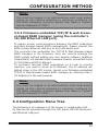
3.3.2 Firmware-embedded TCP/IP & web browser-based RAID
manager (using the controller’s 10/100 Ethernet LAN port)........ 49
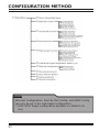
3.4 Configuration Menu Tree.................................................... 49
4. LCD Configuration Menu............................................. 51
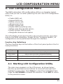
4.1 Starting LCD Configuration Utility....................................... 51
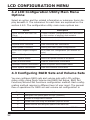
4.2 LCD Configuration Utility Main Menu Options......................... 52
4.3 Configuring RAID Sets and Volume Sets............................... 52
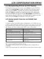
4.4 Designating Drives as Hot Spares........................................ 53
4.5 Using Quick Volume and RAID Set Setup ............................. 53
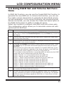
4.6 Using RAID Set and Volume Set Functions ........................... 55
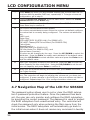
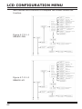
4.7 Navigation Map of the LCD For SR6600-FSU/U3.................... 56
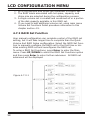
4.7.1 Quick Volume/RAID Setup............................................. 57
4.7.2 RAID Set Function........................................................ 58
4.7.2.1 Create A New RAID Set ........................................... 59
4.7.2.2 Delete Existed RAID Set........................................... 59
4.7.2.3 Expand Existed RAID Set.......................................... 59
4.7.2.4 Activate Incomplete RAID Set................................... 60
4.7.2.5 Create Hot Spare Disk.............................................. 60
4.7.2.6 Delete Hot Spare Disk.............................................. 60
4.7.2.7 Display RAID Set Information.................................... 60
4.7.3 Volume Set Function..................................................... 61
4.7.3.1 Create RAID Volume Set .......................................... 61
4.7.3.1.1 Capacity............................................................. 63
4.7.3.1.2 RAID Level . ....................................................... 63
4.7.3.1.3 Strip Size............................................................ 63
4.7.3.1.4 Volume Name...................................................... 63
4.7.3.1.5 IDE Host Channel (SR6600-FSU)............................ 63
4.7.3.1.6 IDE Drive Select (SR6600-FSU)............................. 64
4.7.3.1.7 SCSI Channel (SR6600-U3)................................... 64
4.7.3.1.8 SCSI ID (SR6600-U3)........................................... 64
4.7.3.1.9 SCSI LUN (SR6600-U3)........................................ 64
4.7.3.1.10 Cache Mode...................................................... 64
4.7.3.1.11 Tag Queuing...................................................... 64
4.7.3.1.12 IDE Xfer Mode (SR6600-FSU).............................. 65
4.7.3.1.13 Max Sync Rate (SR6600-U3)............................... 65
4.7.3.2 Delete Volume Set................................................... 65
4.7.3.3 Modify Volume Set................................................... 67
4.7.3.3.1 Volume Set Migration........................................... 67
4.7.3.4 Check Volume Set Consistency.................................. 67
4.7.3.5 Stop Volume Set Consistency Check........................... 68
4.7.3.6 Display Volume Set Information................................. 68
4.7.4 Physical Drive ............................................................. 68
4.7.4.1 Display Drive Information ........................................ 71
4.7.4.2 Create Pass-Through ............................................... 71
4.7.4.3 Modify Pass-Through ............................................... 71
4.7.4.4 Delete Pass-Through ............................................... 72
4.7.4.5 Identify Selected Drive............................................. 72
4.7.5 RAID System Function.................................................. 73
4.7.5.1 Mute The Alert Beeper . ........................................... 73
4.7.5.2 Alert Beeper Setting . .............................................. 74
4.7.5.3 Change Password.................................................... 74
4.7.5.4 JBOD/RAID Configuration......................................... 74
4.7.5.5 RAID Rebuild Priority................................................ 75
4.7.5.6 Maximum SATA Mode .............................................. 75
4.7.5.7 Disk Capacity Truncation Mode.................................. 75
4.7.5.8 Terminal Port Configuration....................................... 76
4.7.5.9 Restart Controller.................................................... 76
4.7.6 U320 SCSI Target Configuration(SR6600-U3)................... 77
4.7.7 Ethernet Configuration.................................................. 77
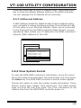
4.7.8 Show System Events.................................................... 77
4.7.9 Clear all Event Buffers................................................... 77
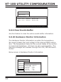
4.7.10 Hardware Information................................................. 77
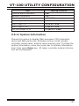
4.7.11 System Information.................................................... 78
5. VT-100 Utility Configuration ...................................... 79
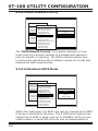
5.1 Configuring RAID Sets and Volume Sets............................... 79
5.2 Designating Drives as Hot Spares........................................ 80
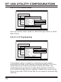
5.3 Using Quick Volume /RAID Setup Configuration..................... 80
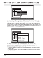
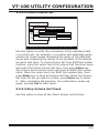
5.4 Using RAID Set/Volume Set Function Method........................ 82
5.5 Main Menu ...................................................................... 84
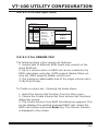
5.5.1 Quick Volume/RAID Setup............................................. 85
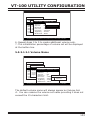
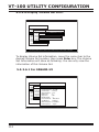
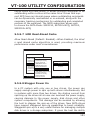
5.5.2 RAID Set Function........................................................ 88
5.5.2.1 Create RAID Set ..................................................... 88
5.5.2.2 Delete RAID Set...................................................... 89
5.5.2.3 Expand RAID Set..................................................... 90
• Migrating........................................................................ 91
5.5.2.4 Activate Incomplete RAID Set................................... 91
5.5.2.5 Create Hot Spare..................................................... 92
5.5.2.6 Delete Hot Spare..................................................... 92
5.5.2.7 RAID Set Information............................................... 93
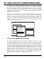
5.5.3 Volume Set Function..................................................... 94
5.5.3.1 Create Volume Set................................................... 94
5.5.3.1.1 For SR6600-U3.................................................... 94
5.5.3.1.1.1 Volume Name................................................... 96
5.5.3.1.1.2 Capacity.......................................................... 97
5.5.3.1.1.3 RAID Level....................................................... 97
5.5.3.1.1.4 Strip Size......................................................... 98
5.5.3.1.1.5 SCSI Channel................................................... 98
5.5.3.1.1.6 SCSI ID........................................................... 99
5.5.3.1.1.7 SCSI LUN......................................................... 99
5.5.3.1.1.8 Cache Mode................................................... 100
5.5.3.1.1.9 Tag Queuing................................................... 100
5.5.3.1.1.10 Max Sync Rate.............................................. 101
5.5.3.1.2 For SR6600-FSU................................................ 101
5.5.3.1.2.1 Volume Name................................................. 103
5.5.3.1.2.2 Capacity........................................................ 104
5.5.3.1.2.3 RAID Level..................................................... 104
5.5.3.1.2.4 Strip Size....................................................... 105
5.5.3.1.2.5 IDE Channel................................................... 105
5.5.3.1.2.6 Drive Select................................................... 106
5.5.3.1.2.7 Cache Mode................................................... 106
5.5.3.1.2.8 Tag Queuing................................................... 107
5.5.3.1.2.9 IDE Xfer Mode................................................ 107
5.5.3.2 Delete Volume Set................................................. 108
5.5.3.3 Modify Volume Set................................................. 108
5.5.3.3.1 Volume Expansion.............................................. 109
5.5.3.3.2 Volume Set Migration......................................... 110
5.5.3.4 Check Volume Set.................................................. 111
5.5.3.5 Stop Volume Set Check.......................................... 111
5.5.3.6 Display Volume Set Info......................................... 112
5.5.3.6.1 For SR6600-U3.................................................. 112
5.5.3.6.2 For SR6600-FSU................................................ 113
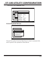
5.5.4 Physical Drives........................................................... 113
5.5.4.1 View Drive Information . ........................................ 114
5.5.4.2 Create Pass-Through Disk....................................... 114
5.5.4.2.1 For SR6600-U3.................................................. 114
5.5.4.2.2 For SR6600-FSU................................................ 115
5.5.4.3 Modify Pass-Through Disk....................................... 115
5.5.4.4 Delete Pass-Through Disk....................................... 116
5.5.4.5 Identify Selected Drive........................................... 116
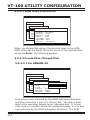
5.5.5 RAID System Function................................................ 117
5.5.5.1 Mute The Alert Beeper . ......................................... 117
5.5.5.2 Alert Beeper Setting............................................... 118
5.5.5.3 Change Password.................................................. 118
5.5.5.4 JBOD/RAID Configuration....................................... 119
5.5.5.5 RAID Rebuild Priority.............................................. 119
5.5.5.6 Maximum SATA Mode............................................. 120
5.5.5.7 HDD Read Ahead Cache......................................... 121
5.5.5.8 Stagger Power On.................................................. 121
5.5.5.9 HDD SMART Status Polling...................................... 122
5.5.5.10 Disk Capacity Truncation Mode.............................. 123
5.5.5.11 Terminal Port Configuration................................... 124
5.5.5.12 Update Firmware................................................. 125
5.5.5.13 Restart Controller................................................ 125
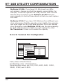
5.5.6 U320 SCSI Target Configuration (SR6600-U3 only)......... 126
5.5.7 Ethernet Configuration ............................................... 127
5.5.7.1 DHCP Function...................................................... 127
5.5.7.2 Local IP address.................................................... 128
5.5.7.3 Ethernet Address................................................... 129
5.5.8 View System Events................................................... 129
5.5.9 Clear Events Buffer..................................................... 130
5.5.10 Hardware Monitor Information.................................... 130
5.5.11 System Information.................................................. 131
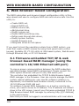
6. Web Browser-based Configuration .......................... 132
6.1 Firmware-embedded TCP/IP & web browser-based RAID man-
ager (using the controller’s 10/100 Ethernet LAN port).............. 132
6.2 Configuring RAID Sets and Volume Sets............................. 133
6.3 Designating Drives as Hot Spares...................................... 133
6.4 Using Quick Volume /RAID Setup Configuration................... 133
6.5 Using RAID Set/Volume Set Function Method...................... 135
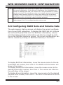
6.6 Configuring RAID Sets and Volume Sets............................. 137
6.6.1 Main Menu ............................................................... 138
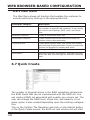
6.7 Quick Create.................................................................. 138
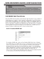
6.8 RAID Set Functions......................................................... 139
6.8.1 Create RAID Set . ...................................................... 139
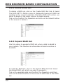
6.8.2 Delete RAID Set......................................................... 140
6.8.3 Expand RAID Set........................................................ 140
6.8.4 Activate Incomplete RAID Set...................................... 141
6.8.5 Create Hot Spare....................................................... 142
6.8.6 Delete Hot Spare........................................................ 142
6.8.7 Rescue RAID Set ...................................................... 142
6.9 Volume Set Functions...................................................... 143
6.9.1 Create Volume Set .................................................... 143
6.9.1.1 For SR6600-U3...................................................... 143
6.9.1.2 For SR6600-FSU.................................................... 145
6.9.3 Modify Volume Set...................................................... 148
6.9.3.1 For SR6600-U3...................................................... 149
6.9.3.2 For SR6600-FSU.................................................... 149
6.9.3.3 Volume Expansion................................................. 149
6.9.3.4 Volume Set Migration............................................. 149
6.9.4 Check Volume Set...................................................... 150
6.9.5 Stop Volume Set Check............................................... 150
6.10 Physical Drive .............................................................. 150
6.10.1 Create Pass-Through Disk.......................................... 151
6.10.1.1 For SR6600-U3.................................................... 151
6.10.1.2 For SR6600-FSU.................................................. 151
6.10.2 Modify Pass-Through Disk.......................................... 152
6.10.2.1 For SR6600-U3.................................................... 152
6.10.2.2 For SR6600-FSU.................................................. 152
6.10.3 Delete Pass-Through Disk.......................................... 153
6.10.4 Identify Drive........................................................... 153
6.11 System Controls............................................................ 153
6.11.1 System Configuration................................................ 153
6.11.1.1 For SR6600-U3.................................................... 153
6.11.1.2 For SR6600-FSU.................................................. 157
6.11.2 U320 SCSI Target Config (SR6600-U3)........................ 159
6.11.3 EtherNet Config ....................................................... 160
6.11.4 Alert By Mail Config ................................................. 160
6.11.5 SNMP Configuration ................................................. 161
6.11.6 NTP Configuration .................................................... 162
• NTP Sever Address......................................................... 162
• Time Zone..................................................................... 162
• Automatic Daylight Saving.............................................. 163
6.11.7 View Events/ Mute Beeper......................................... 163
6.11.8 Generate Test Event.................................................. 163
6.11.9 Clear Events Buffer................................................... 164
6.11.10 Modify Password..................................................... 164
6.11.11 Upgrade Firmware.................................................. 164
6.11.12 Restart Controller .................................................. 164
6.12 Information Menu.......................................................... 165
6.12.1 RAIDSet Hierarchy.................................................... 165
6.12.2 System Information.................................................. 165
6.12.3 Hardware Monitor..................................................... 165
APPENDIX A................................................................. 167
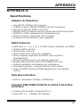
Specifications....................................................................... 167
Adapter Architecture........................................................... 167
RAID Features.................................................................... 167
Disk Bus Interface.............................................................. 167
IDE/SATA to SATA ll Host Bus Interface................................. 167
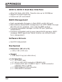
SCSI to SATA ll Host Bus Interface........................................ 168
RAID Management . ........................................................... 168
Software Drivers................................................................ 168
Mechanical........................................................................ 168
Environmental . ................................................................ 169
Electrical........................................................................... 169
Appendix B .................................................................. 170
Upgrading Flash Firmware Programming Utility......................... 170
Establishing the Connection for the RS-232.............................. 170
Upgrade Firmware Through ANSI/VT-100 Terminal Emulation..... 171
Upgrade Firmware Through HTTP Proxy Web Browser Manager... 173
Appendix C................................................................... 175
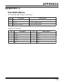
Pin Definitions ..................................................................... 175
Appendix D................................................................... 176
SNMP Operation & Definition.................................................. 176
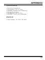
Appendix E................................................................... 178
Technical Support................................................................. 178
INTRODUCTION
1. Introduction
STARDOM SR6600 RAID subsystem is designed for digial video,
digital audio, graphic professionals and small business to extend
storage capacity which as well as a redundant and secure storage solution. For SR6600-FSU comes with Firewire 800, USB2.0
& SATA 1.5Ghz host interfaces and five SATA ll channels for disk
drives. For SR6600-U3 supports 320 SCSI host channel and five
SATA ll channels for disk drives. The RAID subsystem is designed
with a high-performance SATA ll drive bus disk array Controller.
When properly configured, the RAID subsystem can provide nonstop service with a high degree of fault tolerance through the use
of RAID technology and advanced array management features. The
RAID subsystem connects to the host system through Firewire 800
or USB2.0 or eSATA or SCSI interface. The HOST interface on the
host may be located either on the system board, or on a plug-in
host bus adapter (HBA) card.
The RAID subsystem allows easy scalability from RAID 0 to RAID 6.
It can be configured to RAID levels 0, 1, 10, 3, 5 and 6. The RAID 6
function allows two HDD failure without impact on the existing data
and failed drive Data can be reconstructed from the remaining data
and parity drives. RAID configuration and monitoring can be done
through the LCD front control panel or serial port/LAN port.
SR6600 subsystem is the only available RAID solution that does
not require a conventional PCI slot. It uses the standard protocol to
connect the host system controller, just like SCSI or SATA. It is also
a standard part of all major operating systems such as Windows
95/98/2000/NT/ME/XP, Novell, MAC, Linux, UNIX, etc., the host
system does not require additional or proprietary software to work
with the controller.
1.1 System Architecture
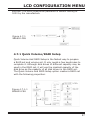
1.1.1 Firewire 800/ USB2.0/SATA Interface
The SR6600-FSU host interface appears to the host system as a
SATA 1.0 target device or a removable Firwire/USB device . The
SATA can support transfer rates up to 150MB per second. The
Firewire 800 can support transfer rates up to 80MB per second.
Both Firewire 800 and SATA 1.0 can concurrently access different
10
INTRODUCTION
volume sets (logical drives).
1.1.2 Ultra 320 Host Interface
The SR6600-U3 appears to the host system as an SCSI Ultra 320
target device. The Ultra 320 can support transfer rates up to 320MB
per second.
1.1.3 Serial ATA ll Drive Interface
STARDOM SR6600 communicates directly with the array’s 5 Serial
ATA ll drives via a built-in SATA interface. When the host is directly
controlling the drives. The RAID subsystem uses the RAID subsystem SATA ll I/O controller chip on each SATA channel to allow the
controller to simultaneously communicate with the host system,
and read or write data on several drives. Up to five disk drives can
be installed to each RAID subsystem.
1.2 RAID subsystem Controller Board
STARDOM SR6600 series have an SATA ll controller which supports SATA ll support up to 5 SATA ll Hard drives. The RAID 6 engine supports a XOR engine and RAID 6 engine for P+Q and parity
generator/checker, one RS-232 and LAN port interface for system
management (Remote Control, and Local Monitor) and an interface
11
INTRODUCTION
to a display/operation panel.
1.2.1 Cache Memory Subsystem
STARDOM SR6600 series’ new high-performance architecture
comes from Intel 80219 I/O processor, a 133MHz/64-bit PCI-X,
and DDR200 memory architecture. The data flow at 133MHz/64
bit PCI-X bus and 64-bit 200Mhz ECC DDR SDRAM makes its high
data throughput. Data can be transferred between the controller and the drives through a high-speed 133MHz/64-bit path at a
burst rate up to 1000MB/S. The system’s overall performance can
support up to Ultra320 SCSI host channels. The controller default
supports 128MB on-board cache.
1.2.2 User Interface
Manual configuration and monitoring can be done through the
LCD front control panel. The firmware also contains an embedded management program that can support the RS-232C (Serial
Console) port out-of-band management. The subsystem can use
any of the interfaces to simplify the setup and management of
their associated disk drives. This out-of-band method is a convenient platform-independent management utility. User can through
this port to implement Bootable CD VT-100, VT-100 Terminal and
HTTP Proxy browser-based management utility.The controller has
embedded the web browser-based RAID manager in the firmware. User can remote manage the RAID system without adding
any user specific software (platform independent) via standard
web browsers directly connected to the 10/100 Ethernet RJ45
LAN port.
1.2.3 Controller Firmware
The system provides RAID levels 0, 1, 10, 3, 5 and 6 RAID configurations. It can be managed either through the LCD control panel
or by the system-embedded configuration utilities. Its high data
availability and protection derives from the following capabilities:
Online Capacity Expansion, Online RAID Level Migration, Dynamic
Volume Extension, Array Roaming, Global Online Spare, Automatic Drive Failure Detection, Automatic Failed Drive Rebuilding, Disk
Hot Spare, and Instant Availability/Background Initialization.
12
INTRODUCTION
The RAID subsystem firmware is stored on the controller flash
ROM and is executed by the Intel 80219 I/O processor. The firmware can also be updated through the RS-232or LAN port without
the need to replace any hardware chips. During the controller
ROM flash process, it is possible for a problem to occur resulting
in corruption of the controller firmware. A corrupted firmware in
the controller firmware would make the controller inoperable and
bring the system down. The Redundant Flash provides a unique
redundancy feature that helps ensure against controller availability. This reduces the risk of system failure due to firmware crash.
In addition to the stored programs in ROM. The NVRAM store
the event log and lists of pending write operation issued to any
drives. These data are checksum protected so that after a power
failure, the controller will consistency for all check outstanding
writes on region.
1.3 RAID Concept
1.3.1 RAID Set
A RAID Set is a group of disk containing one or more volume sets.
It has the following features in the RAID controller. A volume Set
must be created either on an existing RAID set or on a group of
available individual disks (disks that are not yet a part of an RAID
set). If there are pre-existing RAID sets with available capacity
and enough disks for specified RAID level desired, then the volume
set will be created in the existing RAID set of the user’s choice. If
physical disk of different capacity are grouped together in a RAID
set, then the capacity of the smallest disk will become the effective
13
INTRODUCTION
capacity of all the disks in the RAID set.
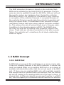
1.3.2 Volume Set
A Volume Set is seen by the host system as a single logical device.
It is organized in a RAID level with one or more physical disks.
RAID level refers to the level of data performance and protection of
a Volume Set. A Volume Set capacity can consume all or a portion
of disk capacity available in a RAID Set. Multiple Volume Sets can
exist on a group of disks in a RAID Set.
In the illustration below, Volume 1 can be assigned a RAID 5 level
of operation while Volume 0 might be assigned a RAID 10 level of
operation.
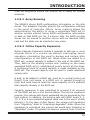
1.3.3 Easy of Use Features
1.3.3.1 Instant Availability/Background Initialization
RAID 0 and RAID 1 volume sets can be used immediately after
creation because they do not create parity data. However, RAID
3, 5 and 6 volume sets must be initialized to generate parity
information. In Normal Initialization, the initialization proceeds
as a background task, and the volume set is fully accessible for
system reads and writes. The operating system can instantly
access the newly created arrays without requiring a reboot and
without waiting for initialization to complete. Furthermore, the
RAID volume set is protected against a single disk failure while
initialing. If using Fast Initialization, the initialization process
14
INTRODUCTION
must be completed before the volume set is ready for system
accesses.
1.3.3.2 Array Roaming
The SR6600 stores RAID configuration information on the disk
drives. The adapters therefor protect the configuration settings
in the event of controller failure. Array roaming allows the
administrators the ability to move a completele RAID set to
another system without losing RAID configuration information
or data on that RAID set. So, if a server fails, the RAID set disk
drives can be moved to another server with an identical RAID
card and the disks can be inserted in any order.
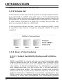
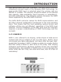
1.3.3.3 Online Capacity Expansion
Online Capacity Expansion makes it possible to add one or more
physical drives to a volume set without interrupting server
operation, eliminating the need to backup and restore after
reconfiguration of the RAID set. When disks are added to a
RAID set, unused capacity is added to the end of the RAID set.
Then, data on the existing volume sets (residing on the newly
expanded RAID set) is redistributed evenly across all the disks.
A contiguous block of unused capacity is made available on the
RAID set. The unused capacity can be used to create additional
volume sets.
A disk, to be added to a RAID set, must be in normal mode (not
failed), free (not spare, in a RAID set, or passed through to
host) and must have at least the same capacity as the smallest
disk capacity already in the RAID set.
Capacity expansion is only permitted to proceed if all volumes
on the RAID set are in the normal status. During the expansion
process, the volume sets being expanded can be accessed by the
host system. In addition, the volume sets with RAID levels 0, 1,
10, 3, 5 or 6 are protected against data loss in the event of disk
failure(s). In the case of disk failure, the volume set transitions
from “migrating” state to “migrating+degraded“ state. When the
expansion is completed, the volume set would then transition to
“degraded” mode. If a global hot spare is present, then it further
15
INTRODUCTION
transitions to the “rebuilding” state.
The expansion process is illustrated as following figure.
The RAID subsystem controller redistributes the original volume
set over the original and newly added disks, using the same
fault-tolerance configuration. The unused capacity on the expand
RAID set can then be used to create an additional volume set,
with a different fault tolerance setting (if required by the user.)
The RAID subsystem controller redistributes the original volume
set over the original and newly added disks, using the same
fault-tolerance configuration. The unused capacity on the expand
RAID set can then be used to create an additional volume sets,
with a different fault tolerance setting if user need to change.
16
INTRODUCTION
1.3.3.4 Online RAID Level and Stripe Size Migration
For those who wish to later upgrade to any RAID capabilities,
a system with online RAID level/stripe size migration allows a
simplified upgrade to any supported RAID level without having
to reinstall the operating system.
The SR6600 can migrate both the RAID level and stripe size of
an existing volume set, while the server is online and the volume
set is in use. Online RAID level/stripe size migration can prove
helpful during performance tuning activities as well as when
additional physical disks are added to the SATA RAID controller.
For example, in a system using two drives in RAID level 1, it is
possible to add a single drive and add capacity and retain fault
tolerance. (Normally, expanding a RAID level 1 array would
require the addition of two disks). A third disk can be added
to the existing RAID logical drive and the array can then be
migrated from RAID level 1 to 5. The result would be parity fault
tolerance and double the available capacity without taking the
system down. A forth disk could be added to migrate to RAID
level 6. It is only possible to migrate to a higher RAID level by
adding a disk; disks in an existing array can’t be reconfigured
for a higher RAID level without adding a disk.
Online migration is only permitted to begin. If all volume to
be migrated are in the normal mode. During the migration
process, the volume sets being migrated are accessed by the
host system. In addition, the volume sets with RAID levels 1,
10, 3, 5 or 6 are protected against data loss in the event of disk
failure(s). In the case of disk failure, the volume set transitions
from migrating state to (migrating+degraded) state. When the
migration is completed, the volume set transitions to degraded
mode. If a global hot spare is present, then it further transitions
to rebuilding state.
1.3.3.5 Online Volume Expansion
Performing a volume expansion on the controller is the process
of growing the size of a volume. A more flexible option is for the
array to concatenate an additional drive into the RAID set and
then expand the volumes on the fly. This happens transparently
17
INTRODUCTION
while the volumes are online, but, at the end of the process,
the operating system will detect free space at after the existing
volume; the free space will not automatically be incorporated
into the existing operating system partition.
Windows, NetWare, and other advanced operating systems
support volume expansion, which enables you to incorporate
the additional free space within the volume into the operating
system partition. The operating system partition is extended to
incorporate the free space so it can be used by the operating
system without creating a new operating system partition.
You can use the Diskpart.exe command line utility, included with
Windows Server 2003 or the Windows 2000 Resource Kit, to
extend an existing partition into free space in the Dynamic disk.
Third-party software vendors have created utilities that can be
used to repartition disks without data loss. Most of these utilities
work offline. Partition Magic is one such utility.
1.4 High availability
1.4.1 Global Hot Spares
A Global Hot Spare is an unused online available drive, which is
ready for replacing the failure disk. The Global Hot Spares is one
of the most important features that SR6600 subsystem RAID
controller provide to deliver a high degree of fault-tolerance. A
global Hot Spare is a spare physical drive that has been marked
as a global hot spare and therefore is not a member of any RAID
set. If a disk drive used in a RAID Volume Set fails, then the
Global Hot spare will automatically take its place and he data
previously located on the failed drive is reconstructed on the
Global Hot spare.
For this feature to work properly, the global hot spare must have
at least the same capacity as the drive it replaces. Global Hot
spares only work with RAID level 1, 10, 3, 5, or 6 volume set. You
can configure up to three Global hot spares with SR6600.
18
INTRODUCTION
The Create Hot Spare option gives you the ability to define a
global hot spare disk drive. To effectively use the global hot spare
feature, you must always maintain at least one drive that is
marked as a global spare.
Important:
The hot spare must have at least the same capacity as the drive
it replaces.
1.4.2 Hot-Swap Disk Drive Support
The SATA RAID controller includes a protection circuit that
supports the replacement of SATA hard disk drives without having
to shut down or reboot the system. A removable hard drive tray
can deliver “hot swappable” fault-tolerant RAID solutions at prices
much less than the cost of conventional SCSI hard disk SATA
RAID controllers. This feature provides advanced fault tolerant
RAID protection and “online” drive replacement.
1.4.3 Auto Declare Hot-Spare
If a disk drive is brought online into a system operating in
degraded mode, SR6600-FSU/6020 subsystem RAID controller
will automatically declare the new disk as a spare and begin
rebuilding the degraded volume. The Auto Declare Hot-Spare
function requires that the smallest drive contained within the
volume set in which the failure occurred.
In the normal status, the newly installed drive will be reconfigured
an online free disk. But, the newly-installed drive is automatically
assigned as a hot spare if any hot spare disk was used to rebuild
and without new installed drive replaced it. In this condition,
the Auto Declare Hot-Spare status will disappeared if the RAID
subsystem has since powered off/on.
The Hot-Swap function can be used to rebuild disk drives in arrays
with data redundancy such as RAID level 0, 1, 10, 3, 5, and 6.
19
INTRODUCTION
1.4.4 Auto Rebuilding
If a hot spare is available, the rebuild starts automatically when
a drive fails. SR6600 subsystem RAID controller automatically
and transparently rebuild failed drives in the background at userdefinable rebuild rates.
If a hot spare is not available, the failed disk drive must be
replaced with a new disk drive so that the data on the failed drive
can be automatically rebuilt and so that fault tolerance can be
maintained.
The SR6600 subsystem RAID controller will automatically restart
the system and the rebuild process if the system is shut down
or powered off abnormally during a reconstruction procedure
condition.
When a disk is Hot Swapped, although the system is functionally
operational, the system may no longer be fault tolerant. Fault
tolerance will be lost until the removed drive is replaced and the
rebuild operation is completed.
During the automatic rebuild process, system activity will continue
as normal, however, the system performance and fault tolerance
will be affected.
1.4.5 Adjustable Rebuild Priority
Rebuilding a degraded volume incurs a load on the RAID
subsystem. The SR6600 subsystem RAID controller allows the
user to select the rebuild priority to balance volume access and
rebuild tasks appropriately. The Background Task Priority is a
relative indication of how much time the controller devotes to a
background operation, such as rebuilding or migrating.
The RAID subsystem allows user to choose the task priority (Ultra
Low (5%), Low (20%), Medium (50%), High (80%)) to balance
volume set access and background tasks appropriately. For high
array performance, specify an Ultra Low value. Like volume
initialization, after a volume rebuilds, it does not require a system
reboot.
20
INTRODUCTION
1.5 High Reliability
1.5.1 Hard Drive Failure Prediction
In an effort to help users avoid data loss, disk manufacturers are
now incorporating logic into their drives that acts as an "early
warning system" for pending drive problems. This system is called
SMART. The disk integrated controller works with multiple sensors
to monitor various aspects of the drive's performance, determines
from this information if the drive is behaving normally or not, and
makes available status information to RAID controller firmware
that probes the drive and look at it.
S.M.A.R.T. can often predict a problem before failure occurs.
SR6600 controllers will recognize a S.M.A.R.T. error code and
notify the administer of an impending hard drive failure.
1.5.2 Auto Reassign Sector
Under normal operation, even initially defect-free drive media
can develop defects. This is a common phenomenon. The bit
density and rotational speed of disks is increasing every year,
and so is the potential of problems. Usually a drive can internally
remap bad sectors without external help using cyclic redundancy
check (CRC) checksums stored at the end of each sector.
SATA drives perform automatic defect re-assignment for both
read and write errors. Writes are always completed - if a location
to be written is found to be defective, the drive will automatically
relocate that write command to a new location and map out the
defective location. If there is a recoverable read error, the correct
data will be transferred to the host and that location will be
tested by the drive to be certain the location is not defective. If
it is found to have a defect, data will be automatically relocated,
and the defective location is mapped out to prevent future write
attempts.
In the event of an unrecoverable read error, the error will be
reported to the host and the location flagged as potentially
defective. A subsequent write to that location will initiate a sector
test and relocation should that location have a defect. Auto
Reassign Sector does not affect disk subsystem performance
21
INTRODUCTION
because it runs as a background task. Auto Reassign Sector
discontinues when the operating system makes a request.
1.5.3 Consistency Check
A consistency check is a process that verifies the integrity of
redundant data. For example, performing a consistency check
of a mirrored drive assures that the data on both drives of the
mirrored pair is exactly the same. To verify RAID 3, 5 or 6 redundancy, a consistency check reads all associated data blocks, computes parity, reads parity, and verifies that the computed parity
matches the read parity.
Consistency checks are very important because they detect and
correct parity errors or bad disk blocks in the drive. A consistency check forces every block on a volume to be read, and any
bad blocks are marked; those blocks are not used again. This is
critical and important because a bad disk block can prevent a disk
rebuild from completing. We strongly recommend that you run
consistency checks on a regular basis—at least once per week.
Note that consistency checks degrade performance, so you should
run them when the system load can tolerate it.
1.6 Data Protection
1.6.1 RECOVERY ROM
The RAID subsystem firmware is stored on the controller flash
ROM and is executed by the I/O processor. The firmware can also
be updated through Ethernet port (if equipped) without the need
to replace any hardware chips. During the controller firmware upgrade flash process, it is possible for a problem to occur resulting
in corruption of the controller firmware. With our Redundant Flash
image feature, the controller will revert back to the last known
version of firmware and continue operating. This reduces the risk
of system failure due to firmware crash.
1.7 Understanding RAID
RAID is an acronym for Redundant Array of Independent Disks. It
is an array of multiple independent hard disk drives that provides
22
INTRODUCTION
high performance and fault tolerance. The SATA RAID controller
implements several levels of the Berkeley RAID technology. An
appropriate RAID level is selected when the volume sets are
defined or created. This decision should be based on the desired
disk capacity, data availability (fault tolerance or redundancy),
and disk performance. The following section discusses the RAID
levels supported by the SATA RAID controller.
The SATA RAID controller makes the RAID implementation and
the disks’ physical configuration transparent to the host operating
stem. This means that the host operating system drivers and
software utilities are not affected, regardless of the RAID level
selected. Correct installation of the disk array and the controller
requires a proper understanding of RAID technology and the
concepts.
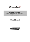
1.7.1 RAID 0
RAID 0, also referred to as striping, writes stripes of data across
multiple disk drives instead of just one disk drive. RAID 0 does
not provide any data redundancy, but does offer the best highspeed data throughput. RAID 0 breaks up data into smaller blocks
and then writes a block to each drive in the array. Disk striping
enhances performance because multiple drives are accessed
simultaneously; the reliability of RAID Level 0 is less because the
entire array will fail if any one disk drive fails, due to a lack of
redundancy.
23
INTRODUCTION
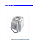
1.7.2 RAID 1
RAID 1 is also known as “disk mirroring”; data written to one disk
drive is simultaneously written to another disk drive. Read performance may be enhanced if the array controller can, in parallel,
accesses both members of a mirrored pair. During writes, there
will be a minor performance penalty when compared to writing
to a single disk. If one drive fails, all data (and software applications) are preserved on the other drive. RAID 1 offers extremely
high data reliability, but at the cost of doubling the required data
storage capacity.
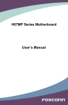
1.7.3 RAID 10
RAID 10 is a combination of RAID 0 and RAID 1, combing stripping with disk mirroring. RAID Level 10 combines the fast performanceof Level 0 with the data redundancy of Leve1 1. In
this configuration, data is distributed across several disk drives,
similar to Level 0, which are then duplicated to another set of
drive for data protection. RAID 10 has been traditionally implemented using an even number of disks, some hybrids can use an
odd number of disks as well. Figure 2 illustrates an example of a
hybrid RAID 10 array comprised of five disks; A, B, C, D and E. In
this configuration, each strip is mirrored on an adjacent disk with
wrap-around. In fact this scheme - or a slightly modified version
of it - is often referred to as RAID 1E and was originally proposed
by IBM. When the number of disks comprising a RAID 1E is even,
the striping pattern is identical to that of a traditional RAID 10,
24
INTRODUCTION
with each disk being mirrored by exactly one other unique disk.
Therefore, all the characteristics for a traditional RAID 10 apply to
a RAID 1E when the latter has an even number of disks. NitroAV
RAID 10 offers a little more flexibility in choosing the number of
disks that can be used to constitute an array. The number can be
even or odd.
1.7.4 RAID 3
RAID 3 provides disk striping and complete data redundancy
though a dedicated parity drive. RAID 3 breaks up data into
smaller blocks, calculates parity by performing an exclusive-or
on the blocks, and then writes the blocks to all but one drive in
the array. The parity data created during the exclusive-or is then
written to the last drive in the array. If a single drive fails, data
is still available by computing the exclusive-or of the contents
corresponding strips of the surviving member disk. RAID 3 is best
for applications that require very fast data- transfer rates or long
25
INTRODUCTION
data blocks.
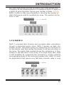
1.7.5 RAID 5
RAID 5 is sometimes called striping with parity at byte level. In
RAID 5, the parity information is written to all of the drives in the
controllers rather than being concentrated on a dedicated parity
disk. If one drive in the system fails, the parity information can
be used to reconstruct the data from that drive. All drives in the
array system can be used for seek operations at the same time,
greatly increasing the performance of the RAID system. This
relieves the write bottleneck that characterizes RAID 4, and is the
primary reason that RAID 5 is more often implemented in RAID
arrays.
1.7.6 RAID 6
RAID 6 provides the highest reliability, but is not yet widely
used. It is similar to RAID 5, but it performs two different parity
computations or the same computation on overlapping subsets
of the data. RAID 6 can offer fault tolerance greater than RAID
1 or RAID 5 but only consumes the capacity of 2 disk drives for
distributed parity data. RAID 6 is an extension of RAID 5 but uses
a second, independent distributed parity scheme. Data is striped
on a block level across a set of drives, and then a second set of
parity is calculated and written across all of the drives.
26
INTRODUCTION
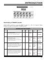
Summary of RAID Levels
SATA RAID controller supports RAID Levels 0, 1, 10, 3, 5 and 6. Table
below provides a summary of RAID levels.
Features and Performance
RAID
Level
Description
0
1
10
3
Min.
Drives
Max.
Drives
Data
Reliability
Data
Transfer
Rate
I/O Request
Rates
Also known as stripping
Data distributed across multiple drives in
the array. There is no data protection
1
5
No data
Protection
Very High
Very High
for
Both Reads
and Writes
Also known as mirroring
All data replicated on N
Separated disks. N is almost always 2.
This is a high availability
Solution, but due to the 100% duplication,
it is also a costly solution.
2
2
Lower
than RAID
6;
Higher
than
RAID 3,5
Reads are
higher
Than a
single disk;
Reads are
twice faster
than a single
disk;
Writes
similar to a
single disk
Write are
similar to a
single disk.
Also known Block-Interleaved Parity.
Data and parity information is subdivided
and distributed across all disk. Parity must
be the equal to the smallest disk capacity
in the array. Parity information normally
stored on a dedicated parity disk.
3
Lower
than RAID
6;
Higher
than
RAID 3,5
Transfer
rates more
similar
to RAID
1 than
RAID 0
Reads are
twice faster
than a single
disk;
Also known Bit-Interleaved Parity.
Data and parity information is subdivided
and distributed across all disk. Parity must
be the equal to the smallest disk capacity
in the array. Parity information normally
stored on a dedicated parity disk.
3
Lower
than RAID
1, 10, 6;
Reads are
similar to
RAID 0;
Higher
than a
single
drive
Writes are
slower
than a
single disk
Reads are
similar twice
faster than a
single disk;
5
5
Writes are
similar to a
single disk.
Writes are
similar to a
single disk.
27
INTRODUCTION
5
6
28
Also known Block-Interleaved Distributed
Parity.
Data and parity information is subdivided
and distributed across all disk. Parity must
be the equal to the smallest disk capacity
in the array. Parity information normally
stored on a dedicated parity disk.
3
RAID 6 provides highest reliability, but not
widely used. Similar to RAID 5, but does
two different parity computations or the
same computation on overlapping subsets
of the data. The RAID 6 can offer fault tolerance greater that RAID 1 or RAID 5 but
only consumes the capacity of 2 disk drives
for distributed parity data.
4
5
5
Lower
than RAID
1, 10, 6;
Reads are
similar to
RAID 0;
Reads are
similar to
RAID 0;
Higher
than a
single
drive.
Writes are
slower
than a
single disk.
Writes are
slower than
a single
disk.
highest
reliability
Reads/
Writes are
similar to
RAID 5.
Reads are
similar to
RAID 0;
Writes are
slower than
the RAID 5.
HARDWARE INSTALLATION
2. Hardware Installation
This section describes the procedures for installing SR6600 series.
2.1 Overview
This chapter describes how to install the RAID Subsystem and connect UDMA/SATA ll drives to make the RAID subsystem ready to
use. The following contains step-by-step instructions to successfully install your new RAID subsystem in your computer system.
2.2 RAID Subsystem Requirements
SR6600 is a stand alone RAID subsystem with standard Firewire
800 or USB2.0 or SATA 1.5GHz or SCSI Ultra 320 (SR6600-U3).
Before installing SR6600, please verify that the channel on host
system is working well.
2.3 Step Action
1. Unpack the RAID subsystem and inspect for damage. Make
sure all items are in the package.
2. Identify RAID subsystem Part.
3. Turn off the computer.
4. Mounting RAID subsystem in system.
5. Connecting HOST Firewire800/USB2.0/SATA/(SR6600-5SWBS1) or SCSI Ultra 320(SR6600-U3) to RAID subsystem.
6. Loading Drive to the Drive Tray.
7. RAID Creation Method.
8. Turn on the host computer power.
9. Configure the RAID subsystem.
• Step 1 Unpack
Unpack and install the hardware in a static-free environment. The
RAID subsystem is packed inside an anti-static bag between two
sponge sheets. Remove it and inspect it for damage. If the RAID
subsystem appears damaged, or if any items of the contents listed
below are missing or damaged, please contact your dealer or distributor immediately.
29
HARDWARE INSTALLATION
Checklist
The RAID subsystem kit may have included the following items in
the ship package:
Item
Quantity
SR6600
1 (For
����������������
SR6600-FSU)
USB cable
1 (For
����������������
SR6600-FSU)
1394b cable
1 (For
����������������
SR6600-FSU)
eSATA cable
1 (For
����������������
SR6600-FSU)
SCSI cable
1 (For SR6600-U3)
Terminator
1 (For
���������������
SR6600-U3)
RS232 cable
1
Removable Tray Module 5
User's Guide
1
CD Title
1
Power code
1
Accessories bag 1
(including 22 x 6#-32 screws and 10 x M3 X 6 screws, 2 x keys)
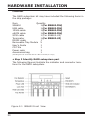
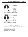
• Step 2 Identify RAID subsystem part
The following figures illustrate the indicator and connector locations for the RAID subsystem.
Figure 2-1 SR6600 Front View
30
HARDWARE INSTALLATION
• Step 3 Power Down the System
• Step 4 Loading Drive to the Drive Tray
The RAID subsystem supports five channel SATA ll channels. For
SATA ll drive each channel can run up to 300MB/S.
1.
2.
3.
4.
Press the key in the lock hole.
Demount the transport holder.
Mount the HDD into the tray.
Push the tray with the HDD back to the case.
31
HARDWARE INSTALLATION
• Step 5 Connecting RAID subsystem Power
Connect AC power cable to the power connector on the rear side
of the RAID subsystem.
• Step 6 Connecting SR6600-FSU RAID subsystem to
HOST Channel
1. Connect the eSATA/USB2.0/Firewire 800 cable to RAID
subsystem eSATA/USB2.0/Firewire 800 connector on rear Panel
of SR6600.
2. There are two Firewire 800 connectors on SR6600 Rear Panel to
support daisy-chained configuration.
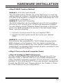
• Step 7 Connecting SR6600-U3 RAID Subsystem to
HOST SCSI Channel
There are two SCSI connectors are provided on the back of the
RAID subsystem for connecting the array to SCSI HOST Adapter.
Installation of the RAID subsystem is very similar to the installation of a standard SCSI drive. Refer to your system and/or SCSI
host adapter manual for additional installation procedures that
may apply to your system or host adapter. By installing HOST
SCSI Channel and RAID subsystem using the SCSI cables included
in your kits.
Follow these steps to connect HOST SCSI Channel and RAID subsystem:
1. The RAID subsystem is the last internal device in the
daisy-chained configuration.
a. Add the other SCSI LVD cable supplied with the RAID subsystem kit to its SCSI- OUT connector and place an LVD
SCSI active terminator on the other end of this connector.
2. The RAID subsystem is the first internal device in the
daisy-chained configuration.
a. Plug the SCSI cable supplied with the RAID subsystem kit to
the SCSI adapter internal connector and the its SCSI-IN
connector.
b. Add the SCSI LVD cable supplied with the SCSI adapter kit
to RAID subsystem SCSI OUT connector. The end of the
SCSI bus farthest from its SCSI OUT must have a
terminator installed.
32
HARDWARE INSTALLATION
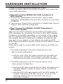
• Step 8 RAID Creation Method
Method 1: LCD Panel with Keypad
The LCD status panel informs you of the Disk Array’s current operating status at a glance. For additional information on using the
LCD panel and keypad to configure the RAID subsystem see “LCD
Configuration” on Chapter 6.
Method 2: Serial Port Connection
The RAID subsystem can be configured via a VT-100 compatible
terminal or a PC running a VT-100 terminal emulation program.
You can attach a serial (Character-Based) terminal or server com
port to the RAID subsystem for access to the text-based Setup
Menu, note the following:
1. Connect a serial terminal to the port labelled COM1.
2. Connect the Host system serial port to the port labelled
COM1.
Method 3: Lan Port Connection
The controller has embedded the TCP/IP & Web Browser-based
RAID manager in the firmware. User can remote manage the
RAID system without adding any user specific software (platform
independent) via standard web browsers directly connected to the
10/100 Ethernet RJ45 LAN port.
• Step 9 Turn on the host computer Power
• Step 10 Configure RAID Subsystems
You can configure RAID subsystem either through the LCD Configuration utility or RS232C/LAN port out of band management
utility. The RAID subsystem supports VT-100 terminal or CD-ROM
bootable VT-100 utility and HTTP Proxy web-browser management
through the RS-232C port. Please reference the Chapter 4, Chapter 5 and Chapter 6 for the configuration.
33
HARDWARE INSTALLATION
Note: SCSI Termination
All SCSI buses require termination on both ends of the bus to
prevent signal degradation. Most SCSI card supplies the termination on the origination end of the SCSI bus. Termination for
the opposite end if the bus is provide by the vendor.
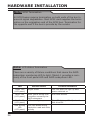
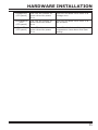
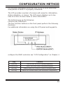
Note: LCD status Termination
There are a variety of failure conditions that cause the RAID
subsystem monitoring LED to light. Table1-1 provides a summary of the front panel LED and RAID subsystem LED.
LED
34
Normal Status
Problem Indication
Power LED
(LCD panel)
Bright Green
This LED does not light up after
power switched on
BUSY LED
(LCD panel)
Blink yellow during host
computer accessing the
RAID subsystem
LED never flickers
FAULT LED
(LCD panel)
LED never light up
This LED light up: “Red”, when the
disk drive fail
Disk Activity
LED
(LCD panel)
This LED blinks during
hard drive read and write
activity
HARDWARE INSTALLATION
Voltage LED
(LCD panel)
This LED will remain on
green when the power
is on
This LED will blink red if there is a
voltage error
Themperature
LED
(LCD panel)
This LED will remain on
green when the power
is on
This LED will blink red if there is a
fan problem
Fan LED
(LCD panel)
This LED will remain on
green when the power
is on
This LED will blink red if the internal
temperature rises above the Spec
setting
35
HARDWARE INSTALLATION
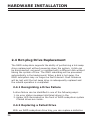
2.4 Hot-plug Drive Replacement
The RAID subsystem supports the ability of performing a hot-swap
drive replacement without powering down the system. A disk can
be disconnected, removed, or replaced with a different disk without
taking the system off-line. The RAID rebuilding will be processed
automatically in the background. When a disk is hot swap, the
RAID subsystem may no longer be fault tolerant. Fault tolerance
will be lost until the hot swap drive is subsequently replaced and
the rebuild operation is completed.
2.4.1 Recognizing a Drive Failure
A drive failure can be identified in one of the following ways:
1. An error status message lists failed drives in the.
2. Amber LED illuminates on the front of RAID subsystem system
if failed drives are inside.
2.4.2 Replacing a Failed Drive
With our RAID subsystem drive tray, you can replace a defective
36
HARDWARE INSTALLATION
physical drive while your computer is still operating. When a new
drive has been installed, data reconstruction will be automatically
started to rebuild the contents of the disk drive.
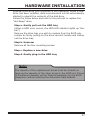
Follow the follow below and refer to the pictures to replace the
“Hot-Swap” drive.
Step a. Gently pull-out the HDD tray
(When a HDD error occurs, the HDD LED indicator lights up “Amber”)
Remove the drive tray you wish to replace from the RAID subsystem by firmly pulling on the drive carrier’s handle and sliding
out the drive tray.
Step b. Unscrew
Remove all the four mounting screws
Step c. Replace a new drive
Step d. Gently plug-in the HDD tray
Note:
The capacity of the replacement drives must be at least as
large as the capacity of the other drives in the RAID set. Drives
of insufficient capacity will be failed immediately by the RAID
subsystem without starting the Automatic Data Rebuild.
37
CONFIGURATION METHOD
3. Configuration Methods
After the hardware installation, the SATA disk drives connected to the
internal RAID subsystem must be configured and the volume set units
initialized before they are ready to use. This can be accomplished by
one of the following methods:
• Front panel touch-control keypad.
• VT100 terminal connected through the controller’s serial port.
• Using HTTP Proxy through the controller’s serial port to access web
browser-based RAID manager in Windows and Linux system.
• Firmware-embedded & web browser-based RAID manager/SNMP a
gent/SMTP via the controller’s 10/100 Ethernet LAN port.
Those user interfaces can access the built-in configuration and administration utility that resides in the controller’s firmware. They provide
complete control and management of the controller and disk arrays,
eliminating the need for additional hardware or software.
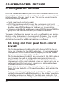
3.1 Using local front panel touch-control
keypad
The front panel keypad and liquid crystal display (LCD) is the primary user interface for the RAID subsystem. All configuration and
management of the controller and its properly connected disk arrays can be performed from this interface.
The front panel keypad and LCD are connected to the RAID subsystem to access the built-in configuration and administration utility that resides in the controller’s firmware. Complete control and
management of the array’s physical drives and logical units can be
performed from the front panel, requiring no additional hardware
or software drivers for that purpose.
This technical manual provides, in quick reference form, procedures that use the built-in LCD panel to configure and operate the
controller.
A touch-control keypad and a liquid crystal display (LCD) mounted
on the front panel of the RAID subsystem is the primary operational interface and monitor display for the disk array controller. This
user interface controls all configuration and management functions
38
CONFIGURATION METHOD
for the RAID subsystem controller and for all or SATA disk array
subsystems to which it is properly connected.
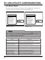
The LCD provides a system of screens with areas for information,
status indication, or menus. The LCD screen displays up to two
lines at a time of menu items or other information.
The Initial screen as the following:
Function Key Definitions
The four function buttons on the front panel perform the following
functions:
For additional information on using the LCD panel and keypad to
configure the RAID controller see ‘‘LCD Configuration” on Chapter 4
Key
Function
Up Arrow
Use to scroll the cursor Upward/Rightward
Down Arrow
Use to scroll the cursor Downward/Leftward
ENT Key
Submit Select ion Function (Confirm a selected Item)
ESC Key
Return to Previous Screen (Exit a selection configuration)
39
CONFIGURATION METHOD
3.2 VT100 terminal (Using the controller’s
serial port)
The serial port on the controller’s back panel can be used in VT100
mode. The firmware-based terminal array management interface
can access the array through this RS-232 port. You can attach a
VT-100 compatible terminal or a PC running a VT-100 terminal
emulation program to the serial port for accessing the text-based
Setup Menu.
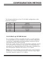
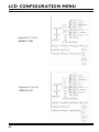
3.2.1 RAID Subsystem RS-232C Port Pin Assignment
To ensure proper communications between the RAID subsystem
and the VT-100 Terminal Emulation, Please configure the VT100
terminal emulation settings to the values shown below:
Keyboard Navigation
Terminal requirment
40
Connection
Null-modem cable
Baud Rate
115,200
Data bits
8
Stop
1
Flow Control
None
CONFIGURATION METHOD
The following definition is the VT-100 RAID configuration utility
keyboard navigation.
Key
Function
Arrow Key
Move cursor
Enter Key
Submit selection function
ESC Key
Return to previous screen
L Key
Line draw
X Key
Redraw
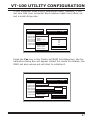
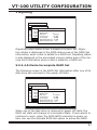
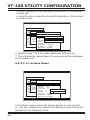
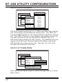
3.2.2 Start-up VT100 Screen
By connecting a VT100 compatible terminal, or a PC operating
in an equivalent terminal emulation mode, all RAID subsystem
monitoring, configuration and administration functions can be
exercised from the VT100 terminal.
There are a wide variety of Terminal Emulation packages, but for
the most part they should be very similar. The following setup
procedure is an example Setup VT100 Terminal in Windows system using Hyper Terminal use Version 3.0 or higher.
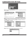
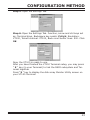
Step 1. From the Desktop open the Start menu. Pick Programs,
Accessories, Communications and Hyper Terminal. Open Hyper
Terminal (requires version 3.0 or higher)
41
CONFIGURATION METHOD
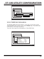
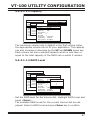
Step 2. Open HYPERTRM.EXE and Enter a name for your Terminal. Click OK.
Step 3. Select an appropriate connecting port in your Terminal.
Click OK. Configure the port parameter settings. Bits per second:
“115200”, Data bits: “8”, Parity:”None”, Stop bits: “1”, Flow
control:”None”. Click OK
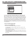
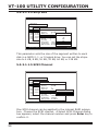
Step 4. Open the File menu, and then open Properties.
42
CONFIGURATION METHOD
Step 5. Open the Settings Tab.
Step 6. Open the Settings Tab. Function, arrow and ctrl keys act
as: Terminal Keys, Backspace key sends: Crtl+H, Emulation:
VT100, Telnet terminal: VT100, Back scroll buffer lines: 500. Click
OK.
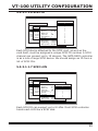
Now, the VT100 is ready to use.
After you have finished the VT100 Terminal setup, you may press
“ X “ key (in your Terminal) to link the RAID subsystem and Terminal together.
Press” X ” key to display the disk array Monitor Utility screen on
your VT100 Terminal.
43
CONFIGURATION METHOD
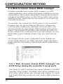
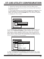
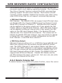
3.3 Web browser-based RAID manager
Firmware-embedded web browser RAID manager is an HTTP
–based application, which utilizes the browser installed on your operating system. Web browser-based RAID manager can be used to
manage all the RAID function via RS-232C port after starts up the
operating system. Please reference the section 3.3 to connect the
controller’s serial port.
The controller also embeds the TCP/IP protocol in the controller’s
firmware. User can use the Ethernet LAN port to configure the
controller without adding any application and device drive. User
can plug and play the web browser RAID manager in the remote
station. The provided LAN interface cable connects the RAID controller’s LAN port into a LAN port from your local network. Use only
shield cable to avoid radiated emission that may cause interruptions.
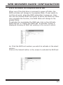
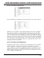
The Storage Console current configuration screen displays the
current configuration of your RAID subsystem. Detail procedures
please reference the Chapter 6 Web Browser-based configuration
method.
3.3.1 Web browser-based RAID manager via
HTTP Proxy (Using the controller’s serial port)
User needs to install Com2Http Proxy Server software to the RAID
controller server system. Com2Http Proxy Server software is an
S/W utility, which allows user through web browser to create
and modify RAID set, volume set, and monitor RAID subsystem
status.
44
CONFIGURATION METHOD
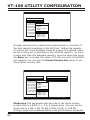
3.3.1.1 Start-up Web Browser-based RAID
Management for Local Administration
SR6600 now offers an alternative means of communication for
the RAID Subsystem - Web Browser-based RAID Management
program.. The Web Browser-based RAID Manager program is an
HTML-based application, which utilizes the browser (IE, Netscape
and Mozilla etc) installed on your monitor station.
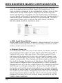
3.3.1.1.1 For Windows
Screen in this section are taken from a Windows/XP installation.
If you are running other Windows, your installing screen may
look different, but the Com2http proxy server installation is
essentially the same.
1. Insert the RAID subsystem CD in the CD-ROM drive.
2. Run the setup.exe file that resides at: CD-ROM:\SR6600
Series\GUI-Com2.Http\windows\setup.exe
3. Click on the Setup file then the Welcome screen appears.
Follow the on-screen prompts to complete Com2Http Proxy
Server software installation.
A program bar appears that measures the progress of
SR6600 Com2http setup. When this screen complete, you
have completed the Com2Http Proxy Server software setup.
4. After a successful installation, the Setup Complete dialog
box of the installation program is displayed. Click the Finish
button to complete the installation.
45
CONFIGURATION METHOD
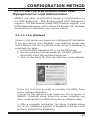
5. Click on the Start Button in the Windows 2000/XP task
bar and then click Program, select the Com2http and run
“Com2Http Proxy Server”. The Com2http dialog box appears.
If user doesn’t want to launch the web browser, goes to step
9.
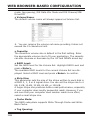
The Parameters for the General Setting:
(1). TCP Port value = 1 ~ 65535.
(2). RAID Connected to value = 1 ~ 10 where 1 for COM1, 2
for COM2 and so on...
(3). BaudRate value = {2400, 4800, 9600, 19200, 38400,
Note:
RAID subsystem controller default setting baud rate is
115200.
57600, 115200}
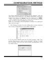
6. To start the com2Http Proxy Server web-browser
management, click the Start Button.
46
CONFIGURATION METHOD
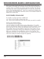
The Enter Network Password dialog screen appears, type the
User Name and Password. The RAID subsystem controller
default User Name is “admin” and the Password is “0000”
. After completing entering user name and password, press
Enter to start-up the Com2Http Proxy Server.
Note: It is strongly recommended to modify the password
after the first login.
7. The Storage Console current configuration screen displays
the current configuration of your RAID subsystem.
8. If you don’t default start-up the web browser, clear “the
Launch Web Browser when server started!!” setting. To start
the Com2Http Proxy Server web-browser management, click
the Start button.
47
CONFIGURATION METHOD
9. User may execute the Com2Http Proxy Server by entering
http://[IP Address] in your web browser.
3.3.1.1.2 For Linux
The following is the Linux installation procedure in the local
server.
1. Insert the RAID subsystem CD in the CD-ROM drive.
2. Run the Com2http file that resides at:CD-ROM:\SR6600
Series\GUI-Com2Http\Linux
3. Usage: Com2Http TCP_PORT COM_PORT BAUDRATE
Parameters: TCP_PORT value = 1 ~ 65535
COM_PORT value = 1 ~ 10 where 1 for COM1, 2 for COM2
and so on...
BAUDRATE value = {2400, 4800, 9600, 19200, 38400,
57600, 115200}
For Example:
Start the Com2Http Proxy Server for TCP_PORT = 6666,
COM_PORT = 1 and BAUDRATE = 115200, user can type “./
Com2Http 6666 1 115200” on command line and enter to
execute it.
2. Execute the Com2Http Proxy Server by entering http://[IP
Address] in the Netscape browser provided with Linux. Note
that Linux prompts you to login to the machine with an ID of
root.
Note:
The RAID subsystem controller default User Name (ID)
is “admin” and the Password is “0000”. It is strongly
recommended to modify the password after the first login.
3.3.1.2 Start-up Web Browser-based RAID Management for Remote Administration
To configure SR6600 RAID subsystem on a remote machine, you
need to know its IP Address. You must first start up your local
Com2Http Proxy Server. (Please reference this chapter section
6.1.2.1). Launch your com2Http Proxy Server by entering http:/
/[IP Address] in the remote web browser.
48
CONFIGURATION METHOD
Note:
You must be logged in as administrator with local admin
rights on the remote machine to remotely configure it.
The RAID subsystem controller default User Name is “admin”
and the Password is “0000”.
3.3.2 Firmware-embedded TCP/IP & web browser-based RAID manager (using the controller’s
10/100 Ethernet LAN port)
To ensure proper communications between the RAID subsystem
and Web browser-based RAID management, Please connect the
RAID system Ethernet LAN port to any LAN switch port.
The controller has embedded the TCP/IP & Web Browser-based
RAID manager in the firmware. User can remote manage the
RAID system without adding any user specific software (platform
independent) via standard web browsers directly connected to the
10/100 Ethernet RJ45 LAN port.
To configure Internal RAID subsystem on a local or remote
machine, you need to know its IP Address. The IP address will
default show in the LCD screen. Launch your firmware-embedded
TCP/IP & Web Browser-based RAID manager by entering http://
[IP Address] in the web browser.
Note:
You must be logged in as administrator with local admin
rights on the remote machine to remotely configure it.
The RAID subsystem controller default User Name is “admin”
and the Password is “0000”.
3.4 Configuration Menu Tree
The following is an expansion of the menus in configuration Utility that can be accessed through the LCD panel, RS-232 serial port
and Ethernet LAN port.
49
CONFIGURATION METHOD
Note:
Ethernet Configuration, Alert By Mail Config, and SNMP Config
can only be set in the web-based configuration.
* U320 SCSI Target configuration available on SR6600-U3
only.
50
LCD CONFIGURATION MENU
4. LCD Configuration Menu
The RAID subsystem LCD configuration utility is a character-based
utility that you can run after powering the unit. Use LCD Configuration
Utility to:
•
•
•
•
•
•
•
•
•
Create RAID set,
Expand RAID set,
Define volume set,
Add physical drive,
Modify volume set,
Modify RAID level/stripe size,
Define pass-through disk drives,
Modify system function and,
Designate drives as hot spares.
The LCD display front panel function keys are the primary user interface for the RAID subsystem. Except for the “Firmware update”, all
configurations can be performed through this interface.
Function Key Definitions
The four function keys at the button of the front panel perform the following functions:
Key
Function
Up Arrow
Use to scroll the cursor Upward/Rightward
Down Arrow
Use to scroll the cursor Downward/Leftward
ENT Key
Submit Select ion Function (Confirm a selected Item)
ESC Key
Return to Previous Screen (Exit a selection configuration)
4.1 Starting LCD Configuration Utility
The main menu appears on the LCD screen, as shown below:
Use the up and down arrow buttons to move left and right and
highlight a menu item. Press Enter to select the highlighted item.
Press the UP/DOWN to browse the selection. Press ESC to return
to the previous screen.
51
LCD CONFIGURATION MENU
4.2 LCD Configuration Utility Main Menu
Options
Select an option and the related information or submenu items display beneath it. The submenus for each item are explained on the
section 4.8.3. The configuration utility main menu options are:
Option
Description
Quick Volume and RAID Set
Setup
Create a default configurations which are based
on the number of physical disk installed
RAID Set Functions
Create a customized RAID set
Volume Set Functions
Create a customized volume set
Physical Drive Functions
View individual disk information
RAID System Functions
Setting the RAID system configurations
U320 SCSI Target Configuration
SCSI Ultra 320 configuration (for SR6600-U3
only)
Ethernet Configuration
Ethernet LAN setting
Show System Events
Record all system events in the buffer
Clear All Event Buffer
Clear all event buffer information
Hardware Monitor Information
Show all system environment status
Show System informatiaon
View the controller information
4.3 Configuring RAID Sets and Volume Sets
You can configure RAID sets and volume sets with LCD configuration utility using Quick Volume And RAID Set Setup, RAID Set
Functions/Volume Set Functions configuration method. Each configuration method requires a different level of user input. The general
flow of operations for RAID set and volume set configuration is:
Step
52
Action
1
Designate hot spares/pass-through (optional)
2
Choose a configuration method
3
Create RAID set using the available physical drives
4
Define volume set using the space in the RAID set
5
Initialize the volume set and use volume set in the HOST OS
LCD CONFIGURATION MENU
4.4 Designating Drives as Hot Spares
To designate drives as hot spares, press Enter to enter the Main
menu. Press UP/DOWN to select the RAID Set Functions option
and then press Enter. All RAID set functions will be displayed.
Press UP/DOWN to select the Create Hot Spare Disk option and
then press Enter. The first unused physical device connected to
the current controller appears: Press UP/DOWN to scroll the unused physical devices and select the target disk to assign as a Hot
Spare and press Enter to designate it as a hot spare.
4.5 Using Quick Volume and RAID Set
Setup
In Quick Volume And RAID Setup Configuration, The RAID set you
create is associated with exactly one volume set, and you can modify the RAID level, stripe size, and capacity. Designating Drives as
Hot Spares will also combine with RAID level in this setup.
Parameter
Setting
Volume Name
Volume Set#00
SCSI Channel/SCSI ID/SCSI LUN
0/0/0 (For SR6600-U3)
IDE Host Channel/IDE Drive Select
0/0-Master (For SR6600-FSU)
Cache Mode
Write Back
Tag Queuing
Yes
Max Sync Rate
Depend your host adapter setting (For
SR6600-U3)
IDE Xfer Mode
Depend your host adapter setting (For
SR6600-FSU)
The volume set default settings will be:
The default setting values can be changed after configuration is
complete.
Follow the steps below to create RAID set using Quick Volume And
53
LCD CONFIGURATION MENU
Step
54
Action
1
Choose Quick Volume /RAID Setup from the main menu. The available
RAID levels with hot spare for the current volume set drive are displayed.
2
Recommend use drives have same capacity in a specific array. If you use
drives with different capacities in an array, all drives in the RAID set will select
the lowest capacity of the drive in the RAID set.
The numbers of physical drives in a specific array determine the RAID levels
that can be implemented with the array.
RAID 0 requires 1 or more physical drives
RAID 1 requires at least 2 physical drives
RAID 1+Spare requires at least 3 physical drives
RAID 3 requires at least 3 physical drives
RAID 5 requires at least 3 physical drives
RAID 6 requires at least 4 physical drives.
RAID 3 +Spare requires at least 4 physical drives
RAID 5 + Spare requires at least 4 physical drives
RAID 6 + Spare requires at least 5 physical drives.
Highlight RAID level for the volume set and press Enter key to confirm.
3
Set the capacity size for the current volume set. After Highlight RAID level
and press Enter key.
The selected capacity for the current volume set is displayed. Using the UP
and DOWN arrow key to create the current volume set capacity size and
press Enter key to confirm. The available stripe sizes for the current volume
set are displayed.
4
Using UP and DOWN arrow key to select the current volume set stripe size
and press Enter key to confirm it. This parameter specifies the size of the
stripes written to each disk in a RAID 0, 1, 5 or 6 Volume Set. You can set the
stripe size to 4 KB, 8 KB, 16 KB, 32 KB, 64 KB, or 128 KB. A larger stripe size
provides better-read performance, especially if your computer does mostly
sequential reads. However, if you are sure that your computer does random
read requests more often, choose a small stripe size.
5
When you are finished defining the volume set, press Enter key to confirm
the Quick Volume And RAID Set Setup function.
6
Press Enter key to define fast initialization or Selected the Background (Instant Available). When background Initialization, the initialization proceeds
as a background task, the volume set is fully accessible for system reads and
writes. The operating system can instantly access to the newly created arrays without requiring a reboot and waiting the initialization complete. When
Initialization, the initialization proceeds must be completed before the volume
set ready for system accesses.
7
Initialize the volume set you have just configured.
8
If you need to add additional volume set, using main menu Create Volume Set
function
LCD CONFIGURATION MENU
4.6 Using RAID Set and Volume Set Functions
In RAID Set Function, you can use the Create RAID Set function to
generate the new RAID set. In Volume Set Function, you can use
the create volume set function to generate its associated volume
set and parameters. If the current controller has unused physical
devices connected, you can choose the Create Hot Spare option in
the RAID Set Function to define a global hot spare.
Select this method to configure new RAID sets and volume sets.
This configuration option allows you to associate volume set with
partial and full RAID set.
Step
Action
1
To setup the Hot Spare (option), choose RAID Set Function from the
main menu. Select the Create Hot Spare and press Enter key to set the
Hot Spare.
2
Choose RAID Set Function from the main menu. Select the Create RAID
Set and press Enter key.
3
Select a Drive For RAID Set window is displayed showing the SATA drive
connected to the current controller.
4
Press UP and DOWN arrow keys to select specific physical drives. Press
the Enter key to associate the selected physical drive with the current
RAID set.
Recommend use drives has same capacity in a specific RAID set. If you
use drives with different capacities in an array, all drives in the RAID set
will select the lowest capacity of the drive in the RAID set.
The numbers of physical drives in a specific RAID set determine the RAID
levels that can be implemented with the RAID set.
RAID 0 requires 1 or more physical drives per RAID set.
RAID 1 requires at least 2 physical drives per RAID set.
RAID 1 + Spare requires at least 3 physical drives per RAID set.
RAID 3 requires at least 3 physical drives per RAID set.
RAID 5 requires at least 3 physical drives per RAID set.
RAID 6 requires at least 4 physical drives per RAID set.
RAID 3 + Spare requires at least 4 physical drives per RAID set.
RAID 5 + Spare requires at least 4 physical drives per RAID set.
RAID 6 + Spare requires at least 5 physical drives.
5
After adding physical drives to the current RAID set as desired, press Yes
to confirm the Create RAID Set function.
6
An Edit The RAID Set Name dialog box appears. Enter 1 to 15 alphanumeric characters to define a unique identifier for a RAID set. The default
RAID set name will always appear as RAID Set. #. Press Enter to finish
the name editing.
55
LCD CONFIGURATION MENU
7
Press Enter key when you are finished creating the current RAID set. To
continue defining another RAID set, repeat step 3. To begin volume set
configuration, go to step 8.
8
Choose Volume Set Function from the Main menu. Select the Create
Volume Set and press Enter key.
9
Choose one RAID set from the Create Volume From RAID Set window.
Press Enter key to confirm it.
10
The volume set attributes screen appers:
The volume set attributes screen shows the volume set default configuration value that is currently being configured. The volume set attributes
are:
RAID Level,
Stripe Size,
SCSI HOST/SCSI ID/SCSI LUN/ (For SR6600-U3)
IDE HOST Channel/IDE Drive Select (For SR6600-FSU)
Cache Mode,
TaggedQueuing,
SCSI Max Rate (For SR6600-U3)
IDE Xfer Mode (For SR6600-FSU), and
Volume Name (number).
All value can be changing by the user. Press the UP/DOWN to select the
attributes. Press the Enter to modify each attribute of the default value.
Using the UP/DOWN to select attribute value and press the Enter to accept the default value.
11
After user completes modifying the attribute, press the ESC to enter the
select Capacity for the volume set. Using the UP/DOWN to set the volume set capacity and press Enter to confirm it.
12
When you are finished defining the volume set, press Enter to confirm
the Create function.
13
Press Enter to define fast initialization and ESC to normal initialization. The controller will begin to initialize the volume set, you have just
configured. If space remains in the RAID set, the next volume set can be
configured. Repeat steps 8 to 13 to configure another volume set.
4.7 Navigation Map of the LCD For SR6600
The password option allows user to set or clear the RAID subsystem’s password protection feature. Once the password has been
set, the user can only monitor and configure the RAID subsystem
by providing the correct password. The password is used to protect
the RAID subsystem from unauthorized entry. The controller will
check the password only when entering the Main menu from the
initial screen. The RAID subsystem will automatically go back to
the initial screen when it does not receive any command in twenty
56
LCD CONFIGURATION MENU
seconds. The RAID subsystem password is default setting at
0000 by the manufacture.
Figure 4.7-1
SR6600-FSU
4.7.1 Quick Volume/RAID Setup
Quick Volume And RAID Setup is the fastest way to prepare
a RAID set and volume set. It only needs a few keystrokes to
complete it. Although disk drives of different capacity may be
used in the RAID set, it will use the smallest capacity of the
disk drive as the capacity of all disk drives in the RAID set.
The Quick Volume And RAID Setup option creates a RAID set
with the following properties:
Figure 4.7.1-1
SR6600-FSU
57
LCD CONFIGURATION MENU
1. All of the physical disk drives are contained in a RAID set.
2. The RAID levels associated with hot spare, capacity, and
stripe size are selected during the configuration process.
3. A single volume set is created and consumed all or a portion
of the disk capacity available in this RAID set.
4. If you need to add additional volume set, using main menu
Volume Set functions Detail procedure references to this
chapter section 4.5.
4.7.2 RAID Set Function
User manual configuration can complete control of the RAID set
setting, but it will take longer time to complete than the Quick
Volume And RAID Setup configuration. Select the RAID Set Function to manually configure the RAID set for the first time or deletes existing RAID set and reconfigures the RAID set.
To enter a RAID Set Functions, press Enter to enter the Main
menu. Press UP/DOWN to select the RAID Set Functions option
and then press Enter to enter further submenus. All RAID set
submenus will be displayed.
Figure 4.7.2-1
58
LCD CONFIGURATION MENU
4.7.2.1 Create A New RAID Set
Detail procedure references to this chapter section 4.6.
4.7.2.2 Delete Existed RAID Set
Press UP/DOWN to choose the Delete Existed RAID Set option.
Using UP/DOWN to select the RAID set number that user want
to delete and then press Enter to accept the RAID set number.
The Confirmation screen appears, then press Enter to accept
the delete existed RAID set function. The double confirmation
screen appears, then press Yes to make sure of the delete existed RAID set function
4.7.2.3 Expand Existed RAID Set
Instead of deleting a RAID set and recreating it with additional
disk drives, the Expand Existed RAID Set function allows the
user to add disk drives to the RAID set that was created.
To expand existed RAID set, press UP/DOWN to choose the
Expand Existed RAID Set option. Using UP/DOWN to select the
RAID set number that user want to expand and then press Enter to accept the RAID set number. If there is an available disk,
then the Select Drive IDE Channel x appears. Using UP/DOWN
to select the target disk and then press Enter to select it. Press
Enter to start expanding the existed RAID set.
The new add capacity will be define one or more volume sets.
Follow the instruction presented in the Volume Set Function to
create the volume sets.
Note:
1. Once the Expand RAID Set process has started, user cannot
stop it. The process must be completed.
2. If a disk drive fails during RAID set expansion and a hot
spare is available, an auto rebuild operation will occur after the
RAID set expansion completes.
59
LCD CONFIGURATION MENU
Migrating occurs when a disk is added to a RAID set. Migration status is displayed in the RAID status area of the RAID Set
information when a disk is added to a RAID set. Migrating status
is also displayed in the associated volume status area of the volume set Information when a disk is added to a RAID set
4.7.2.4 Activate Incomplete RAID Set
When one of the disk drive is removed in power off state, the
RAID set state will change to Incomplete State. If user wants to
continue to work, when the RAID subsystem is power on. User
can use the Activate Incomplete RAID Set option to active the
RAID set. After user complete the function, the RAID State will
change to Degraded Mode.
4.7.2.5 Create Hot Spare Disk
Please refer to this chapter section 4.4: Designating Drives as
Hot Spares.
4.7.2.6 Delete Hot Spare Disk
To delete hot spare, press UP/DOWN to choose the Delete Hot
Spare Disk option. Using UP/DOWN to select the hot spare
number that user want to delete and then press Enter to select
it. The confirmation screens appear and press Enter to delete
the hot spare.
4.7.2.7 Display RAID Set Information
Using UP/DOWN to choose the Display RAID Set Information
option and press Enter. Using UP/DOWN to select the RAID
set number that user want to display. The RAID set information
will be displayed.
Using UP/DOWN to scroll the RAID set information, it shows
RAID Set Name, Total Capacity, Free Capacity, Number of Member Disks, Min. Member Disk Capacity and RAID Set State.
60
LCD CONFIGURATION MENU
4.7.3 Volume Set Function
A volume set is seen by the host system as a single logical device. It is organized in a RAID level with one or more physical
disks. RAID level refers to the level of data performance and protection of a Volume Set. A Volume Set capacity can consume all
or a portion of the disk capacity available in a RAID Set. Multiple
Volume Sets can exist on a group of disks in a RAID Set. Additional Volume Sets created in a specified RAID Set will reside on
all the physical disks in the RAID Set. Thus each Volume Set on
the RAID Set will have its data spread evenly across all the disks
in the RAID Set.
To enter a Volume Set Functions, press Enter to enter the main
menu. Press UP/DOWN to select the Volume Set Functions option and then press Enter to enter further submenus. All volume
set submenus will be displayed.
4.7.3.1 Create RAID Volume Set
To create a volume set, Please refer to this chapter section 4.6:
Using RAID Set and Volume Set Functions. The volume set attributes screen shows the volume set default configuration value
that is currently being configured.
For SR6600-FSU
1. The attributes for SR6600-FSU are RAID Level, Stripe
Size, ache Mode, IDE Host Channel, IDE Drive Select,
Tagged Queuing, IDE Xfer Mode, and Volume Name (num
ber). See Figure 4.7.3.1-1
For SR6600-U3
1. The attributes for SR6600-U3 are RAID Level, Stripe
Size, Cache Mode, SCSI HOST, SCSI ID, SCSI LUN, Tagged
Queuing, SCSI Max Rate, and Volume Name (number). See
Figure 4.7.3.1-2
All value can be changed by user. Press the UP/DOWN to select
attribute. Press the Enter to modify the default value. Using
the UP/DOWN to select attribute value and press the Enter to
accept the default value. The following is the attributes descriptions. Please reference this chapter section 4.6 Using RAID Set
61
LCD CONFIGURATION MENU
and Volume Set Functions to complete the create volume set
function.
Figure 4.7.3.1-1
SR6600-FSU
Figure 4.7.3.1-2
SR6600-U3
62
LCD CONFIGURATION MENU
4.7.3.1.1 Capacity
The maximum volume size is default in the first setting. Enter
the appropriate volume size to fit your application. The capacity
can also increase or decrease by the UP and DOWN arrow key.
Each volume set has a selected capacity which is less than or
equal to the total capacity of the RAID set on which it resides.
4.7.3.1.2 RAID Level
The controller can support RAID level 0, 1, 10, 3, 5 and 6.
4.7.3.1.3 Strip Size
This parameter sets the size of the segment written to each
disk in a RAID 0, 1, 5 or 6 logical drive. You can set the stripe
size to 4 KB, 8 KB, 16 KB, 32 KB, 64 KB, or 128 KB.
A larger stripe size produces better-read performance, especially if your computer does mostly sequential reads. However,
if you are sure that your computer does random reads more
often, select a small stripe size.
4.7.3.1.4 Volume Name
The default volume name will always appear as Volume Set.
#. You can rename the volume set name providing it does not
exceed the 15 characters limit.
4.7.3.1.5 IDE and SATA Host Channel
(SR6600-FSU)
IDE Channels:The SR6600-FSU can support dual host channels
IDE(for Firewire/USB) (Channel 0) and Serial ATA (Channel 1).
Multiple channels can be applied to the RAID subsystem if user
selects the Independent option in the Interface Mode at RAID
System Function. Single channel can be applied to the RAID
subsystem if user selects the Share Volume option in the Interface Mode at RAID System Function. Both IDE and SATA con-
63
LCD CONFIGURATION MENU
nection are setting as Channel 0&1.
4.7.3.1.6 IDE Drive Select (SR6600-FSU)
Host Channel setting at IDE (for Firewire/USB) and SATA host
channel can concurrently access different volume sets. The IDE
(Channel 0) can support one master and one slave volume sets
. The SATA (Channel 1) can support one master volume set.
The Max volume set can be accessed by SR6600-FSU is 3.
Host Channel setting at Share Volume-The SR6600-FSU can
support dual IDE and Serial ATA accesses same volume set. But
user can only connect one channel at one time. If user connects
the Firewire/USB (Host Channel 0), the RAID subsystem supports 2 volumes (Master/Slave). If user connects the SATA, the
RAID subsystem supports 1 volume (Master) (Host Channel 0).
Both IDE and SATA connection are setting as Channel 0&1.
4.7.3.1.7 SCSI Channel (SR6600-U3)
SR6600-U3 only support one ultra 320 SCSI channel.
4.7.3.1.8 SCSI ID (SR6600-U3)
Each SCSI device attached to the SCSI card, as well as the card
itself, must be assigned a unique SCSI ID number. A Wide SCSI
channel can connect up to 15 devices. RAID subsystem is as a
large SCSI device. We should assign an ID from a list of SCSI
IDs.
4.7.3.1.9 SCSI LUN (SR6600-U3)
Each SCSI ID can support up to 8 LUNs. Most SCSI host adapter treats each LUN like a SCSI disk.
4.7.3.1.10 Cache Mode
User can set the cache mode as Write-Through Cache or WriteBack Cache.
4.7.3.1.11 Tag Queuing
The Enabled option is useful for enhancing overall system
64
LCD CONFIGURATION MENU
performance under multi-tasking operating systems. The Command Tag (Drive Channel) function controls the SCSI command tag queuing support for each drive channel. This function should normally remain enabled. Disable this function only
when using older SCSI drives that do not support command tag
queuing.
4.7.3.1.12 IDE Xfer Mode (SR6600-FSU)
The SR6600-FSU RAID subsystem supports ATA133, ATA100,
ATA66, and ATA33 Mode.
4.7.3.1.13 Max Sync Rate (SR6600-U3)
The RAID subsystem supports 320MB/sec for SR6600-U3 as the
highest data transfer rate.
4.7.3.2 Delete Volume Set
Press UP/DOWN to choose the Delete Existed Volume Set option. Using UP/DOWN to select the RAID set number that user
want to delete and press Enter. Scrolling the UP/DOWN to
select the volume set number that user want to delete and press
Enter. The Confirmation screen appears, and then press Enter
to accept the delete volume set function. The double confirmation screen appears, then press Yes to make sure of the delete
volume set function.
65
LCD CONFIGURATION MENU
Figure 4.7.3.2-1
SR6600-FSU
Figure 4.7.3.2-2
SR6600-U3
66
LCD CONFIGURATION MENU
4.7.3.3 Modify Volume Set
Use this option to modify volume set configuration. To modify
volume set attributes from RAID set system function, press
UP/DOWN to choose the Modify Volume Set Attribute option.
Using UP/DOWN to select the RAID set number that user want
to modify and press Enter. Scrolling the UP/DOWN to select
the volume set number that user want to modify and press
Enter. Press Enter to select the existed volume set attribute.
The volume set attributes screen shows the volume set setting
configuration attributes that was currently being configured.
The attributes are RAID Level, Stripe Size, Cache Mode, SCSI
HOST/Fibre SCSI ID/SCSI LUN/Tagged Queuing, SCSI Max Rate,
and Volume Name (number). All value can be modifying by the
user. Press the UP/DOWN to select attribute. Press the Enter
to modify the default value. Using the UP/DOWN to select attribute value and press the Enter to accept the selection value.
Choose this option to display the properties of the selected Volume Set.
4.7.3.3.1 Volume Set Migration
Migrating occurs when a volume set is migrating from one RAID
level to another, a volume set strip size changes, or when a
disk is added to a RAID set. Migration status is displayed in the
volume state area of the Display Volume Set Information when
one RAID level to another, a Volume set strip size changes or
when a disk is added to a RAID set.
4.7.3.4 Check Volume Set Consistency
Use this option to check volume set consistency. To check volume set consistency from volume set system function, press
UP/DOWN to choose the Check Volume Set Consistency option.
Using UP/DOWN to select the RAID set number that user want
to check and press Enter. Scrolling the UP/DOWN to select the
volume set number that user want to check and press Enter.
The Confirmation screen appears, press Enter to start the check
volume set consistency.
67
LCD CONFIGURATION MENU
4.7.3.5 Stop Volume Set Consistency Check
Use this option to stop volume set consistency check. To stop
volume set consistency check from volume set system function,
press UP/DOWN to choose the Stop Volume Set Consistency
Check option and then press Enter to stop the check volume set
consistency.
4.7.3.6 Display Volume Set Information
This option is display volume set information. To display volume
set information from Volume set system function, press UP/
DOWN to choose the Display Volume Set Information option.
Using UP/DOWN to select the RAID set number that user wants
to show and press Enter. Scrolling the UP/DOWN to select
the volume set number that user want to display and press
Enter. The volume set attributes screen shows the volume set
setting configuration value that was currently being configured.
The attributes are RAID Level, Stripe Size, Cache Mode, SCSI
HOST, SCSI ID, SCSI LUN, Tagged Queuing, SCSI Max Rate, and
Volume Name (number). All value cannot be modifying by this
option.
4.7.4 Physical Drive
Choose this option from the Main Menu to select a physical disk
and to perform the operations listed below. To enter a Physical Drive Functions, press Enter to enter the main menu. Press
UP/DOWN to select the Physical Drive Functions option and then
press Enter to enter further submenus. All physical drive submenus will be displayed.
68
LCD CONFIGURATION MENU
Figure 4.7.4-1
SR6600-FSU
69
LCD CONFIGURATION MENU
Figure 4.7.4-2
SR6600-U3
70
LCD CONFIGURATION MENU
4.7.4.1 Display Drive Information
Using UP/DOWN to choose the View Drive Information option and press Enter. Using UP/DOWN to select the drive IDE
number that user want to display. The drive information will be
displayed. The drive information screen shows the Model Name,
Serial Number, Firmware Rev., Device Capacity, Device PIO
Mode, Current UDMA, Supported UDMA, and Device State.
4.7.4.2 Create Pass-Through
Disk is no controlled by the RAID subsystem firmware and thus
cannot be a part of a RAID set. The disk is available to the
operating system as an individual disk. It is typically used on a
system where the operating system is on a disk not controlled
by the RAID subsystem firmware.
Using UP/DOWN to choose the Create Pass-Through Disk option and press Enter. Using UP/DOWN to select the drive IDE
number that user want to create. The drive attributes will be
displayed.
For SR6600-FSU
1. The attributes for SR6600-FSU show the Cache
Model, IDE Host Channel, IDE Drive Select, Tagged Queu
ing, and IDE Xfer Mode.
For SR6600-U3
1. The attributes for SR6600-U3 show the Cache Mode,
SCSI Host, SCSI ID, SCSI LUN, Tagged Queuing, and SCSI
Sync Rate.
All values can be changing by the user. Press the UP/DOWN
to attribue and then press the Enter to modify the efault value.
Using the UP/DOWN to select attribute value and press the Enter to accept the selection value.
4.7.4.3 Modify Pass-Through
Use this option to modify the Pass-Through Disk attributes. To
modify Pass-Through Disk attributes from Pass-Through Disk
pool, press UP/DOWN to choose the Modify Pass-Through
71
LCD CONFIGURATION MENU
Drive option, and then press Enter key. The Select Drive Function menu will show all Pass-Through Drive number items. Using
UP/DOWN to select the Pass-Through Disk that user wants to
modify and press Enter. The attributes screen shows the PassThrough Disk setting value that was currently being configured.
For SR6600-FSU
1. The attributes for SR6600-FSU are the Cache Model,
IDE Host Channel, IDE Drive Select, Tagged Queuing, and
IDE Xfer Mode.
For SR6600-FSU
1. The attributes for SR6600-U3 are the Cache Mode,
SCSI Host, SCSI ID, SCSI LUN, Tagged Queuing, and SCSI
Max Rate.
All value can be modifying by the user. Press the UP/DOWN
arrow keys to select attribute. Press the Enter to modify the default value. Using the UP/ DOWN key to select attribute value
and press the Enter to accept the selection value. After completing the modification, press ESC to enter the confirmation
screen and then press Enter to accept the Modify Pass-Through
Disk function.
4.7.4.4 Delete Pass-Through
To delete pass-through drive from the pass-through drive pool,
press UP/DOWN to choose the Delete Pass-Through Drive option, and then press Enter. The Select Drive Function menu will
show all Pass-Through Drive number items. Using UP/DOWN to
select the Pass-Through Disk that user want to delete and press
Enter. The Delete Pass-Through confirmation screen will appear,
presses Enter to delete it.
4.7.4.5 Identify Selected Drive
To prevent removing the wrong drive, the selected disk HDD
LED Indicator will light for physically locating the selected disk
when the Identify Selected Drive function is selected..
To identify selected drive from the physical drive pool, press
UP/DOWN to choose the Identify Selected Drive option, then
72
LCD CONFIGURATION MENU
press Enter key. The Select Drive function menu will show all
physical drive number items. Using UP/DOWN to select the
Disk that user want to identify and press Enter. The selected
disk HDD LED indicator will flash.
4.7.5 RAID System Function
To enter a RAID System Function, press Enter to enter the Main
menu. Press UP/DOWN to select the RAID System Function option and then press Enter to enter further submenus. All RAID
system submenus will be displayed. Using UP/DOWN to select
the submenus option and then press Enter to enter the selection
function.
4.7.5.1 Mute The Alert Beeper
The Mute The Alert Beeper function item is used to control the
RAID subsystem Beeper. Select the “No” and press Enter key in
73
LCD CONFIGURATION MENU
the dialog box to turn the beeper off temporarily. The beeper will
still activate on the next event.
4.7.5.2 Alert Beeper Setting
The Alert Beeper function item is used to Disabled or Enable the
RAID subsystem controller alarm tone generator. Using the UP/
DOWN to select alert beeper and then press the ENT to accept
the selection. After completing the selection, the confirmation
screen will be displayed and then press ENT to accept the function. Select the Disabled and press Enter key in the dialog box
to turn the beeper off temporarily. The beeper will still activate
on the next event.
4.7.5.3 Change Password
To set or change the RAID subsystem password, press the UP/
DOWN to select Change Password and then press the Enter to
accept the selection. The New Password: screen appears and
enter new password that user want to change. Using the UP/
DOWN to set the password value. After completing the modification, the confirmation screen will be displayed and then press
Enter to accept the function. To disable the password, presses
Enter only in the New Password: column. The existing password
will be cleared. No password checking will occur when entering
the main menu from the starting screen.
4.7.5.4 JBOD/RAID Configuration
For SR6600-FSU
JBOD is an acronym for “Just a Bunch Of Disk”. It represents
a volume set that is created by the concatenation of partitions
on the disks. For the SR6600-FSU, it can only see the first two
disks, when you select the JBOD option. User needs to delete
the RAID set, when you want to change the option from the
RAID to the JBOD function.
For SR6600-U3
JBOD is an acronym for “Just a Bunch Of Disk”. It represents
a volume set that is created by the concatenation of partitions
on the disks. For the SR6600-U3, it can see the five individual
74
LCD CONFIGURATION MENU
disks, when you select the JBOD option. User needs to delete
the RAID set, when you want to change the option from the
RAID to the JBOD function.
4.7.5.5 RAID Rebuild Priority
The “RAID Rebuild Priority” is a relative indication of how much
time the controller devotes to a rebuild operation. The RAID
subsystem allows user to choose the rebuild priority (low, normal, high) to balance volume set access and rebuild tasks appropriately.
To set or change the RAID subsystem RAID Rebuild Priority,
press the UP/DOWN to select RAID Rebuild Priority and press
the Enter to accept the selection. The rebuild priority selection
screen appears and uses the UP/DOWN to set the rebuild value. After completing the modification, the confirmation screen
will be displayed and then press Enter to accept the function.
4.7.5.6 Maximum SATA Mode
Within the subsystem, the SCSI chip acts as a target and 5 SATA
ll bus are connected to the drive. The 5 SATA drive channel can
support up to SATA ll, which runs up to 300MB/s. NCQ is a command protocol in Serial ATA that can only be implemented on
native Serial ATA hard drives. It allows multiple commands to be
outstanding within a drive at the same time. Drives that support NCQ have an internal queue where outstanding commands
can be dynamically rescheduled or re-ordered, along with the
necessary tracking mechanisms for outstanding and completed
portions of the workload. The RAID subsystem allows user
to choose the SATA Mode: SATA150, SAT150+NCQ, SAT300,
SATA300+NCQ.
4.7.5.7 Disk Capacity Truncation Mode
SR6600 RAID controllers use drive truncation so that drives
from differing vendors are more likely to be able to be used as
spares for each other. Drive truncation slightly decreases the usable capacity of a drive that is used in redundant units.
The controller provides three truncation modes in the system
configuration: Multiples Of 10G, Multiples Of 1G, and No
75
LCD CONFIGURATION MENU
Truncation.
Multiples Of 10G: If you have 120 GB drives from different vendors; chances are that the capacity varies slightly. For
example, one drive might be 123.5 GB, and the other 120 GB.
NitroAV drive Truncation mode Multiples Of 10G uses the
same capacity for both of these drives so that one could replace
the other.
Multiples Of 1G: If you have 123 GB drives from different vendors; chances are that the capacity varies slightly. For example,
one drive might be 123.5 GB, and the other 123.4 GB. NitroAV
drive Truncation mode Multiples Of 1G uses the same capacity
for both of these drives so that one could replace the other.
No Truncation: It does not truncate the capacity.
4.7.5.8 Terminal Port Configuration
Parity value is fixed at None.
Handshaking value is fixed at None.
Speed setting values are 1200, 2400, 4800, 9600,
19200,38400, 57600, and 115200.
Stop Bits values are 1 bit and 2 bits.
To set or change the RAID subsystem COMA configuration, press
the UP/DOWN to select COMA Configuration and then press the
ENT to accept the selection. The baud rate setting or number of
stop bit screen appears and uses the UP/DOWN select the setting function. The respect selection screen appears and uses the
UP/DOWN arrow to set the value. After completing the modification, the confirmation screen will be displayed and then press
Enter to accept the function.
4.7.5.9 Restart Controller
Use the Restart Controller function to restart the RAID subsystem controller. To restart the RAID subsystem, press the UP/
DOWN to select Restart Controller and then press the Enter to
accept the selection. The confirmation screen will be displayed
and then press Enter to accept the function.
76
LCD CONFIGURATION MENU
Note:
It only can work properly at Host and Drive without any activity.
4.7.6 U320 SCSI Target Configuration
(SR6600-U3)
Use this feature to Enable/Disable the Ch0 QAS, press Enter to
enter the Main menu. Press UP/DOWN key to select the Show
U320 SCSI Target option, and then press Enter.
4.7.7 Ethernet Configuration
To configuration Ethenet function, press Enter to enter the Main
menu. Press UP/DOWN key to select the option.
4.7.8 Show System Events
To view the RAID subsystem events, press Enter to enter the
Main menu. Press UP/DOWN key to select the Show System
Events option, and then press Enter. The system events will be
displayed. Press UP/DOWN to browse all the system events.
4.7.9 Clear all Event Buffers
Use this feature to clear the entire events buffer information.
To clear all event buffers, press Enter to enter the main menu.
Press UP/DOWN to select the Clear all Event Buffers option, and
then press Enter. The confirmation message will be displayed and
press the Enter to clear all event buffers or ESC to abort the action.
4.7.10 Hardware Information
To view the RAID subsystem controller’s hardware monitor information, press Enter to enter the main menu. Press UP/DOWN
to select the Hardware Information option, and then press Enter.
All hardware information will be displayed. Press UP/DOWN to
77
LCD CONFIGURATION MENU
browse all the hardware information.
The Hardware Monitor Information provides the temperature,
fan speed (chassis fan) and voltage of the internal RAID subsystem. The temperature items list the current states of the controller board and backplane. All items are also unchangeable. The
warning messages will indicate through the LCM, LED and alarm
Item
Warning Condition
Controller Board Temperature
> 60O
Backplane Temperature
> 55O
Controller Fan Speed
< 1900 RPM
Power Supply +12V
< 10.5V or > 13.5V
Power Supply +5V
< 4.7V or > 5.3V
Power Supply +3.3V
< 3.0V or > 3.6V
CPU Core Voltage +1.5V
< 1.35V or > 1.65V
buzzer.
4.7.11 System Information
Choose this option to display Main processor, CPU Instruction
cache and data cache size, firmware version, serial number,
controller model name, and the cache memory size. To check the
system information, press Enter to enter the main menu. Press
UP/DOWN to select the Show System Information option, and
then press Enter. All major controller system information will be
displayed. Press UP/DOWN to browse all the system informa-
78
VT-100 UTILITY CONFIGURATION
5. VT-100 Utility Configuration
The RAID subsystem configuration utility is firmware-based and uses
to configure RAID sets and volume sets. Because the utility resides in
the RAID controller firmware, its operation is independent of the operating systems on your computer. Use this utility to:
•
•
•
•
•
•
•
•
•
•
Create RAID set,
Expand RAID set,
Define volume set,
Add physical drive,
Modify volume set,
Modify RAID level/stripe size,
Define pass-through disk drives,
Update firmware,
Modify system function and,
Designate drives as hot spares.
Keyboard Navigation
The following definition is the VT-100 RAID configuration utility keyboard navigation.
Key
Function
Arrow Key
Move Cursor
Enter Key
Submit selection function
ESC Key
Return to previous screen
L Key
Line Draw
X Key
Redraw
5.1 Configuring RAID Sets and Volume Sets
You can configure RAID sets and volume sets with VT-100 terminal
function using Quick Volume/RAID Setup, or RAID Set/Volume Set
Function configuration method. Each configuration method requires
a different level of user input. The general flow of operations for
RAID set and volume set configuration is:
79
VT-100 UTILITY CONFIGURATION
Step
Action
1
Designate hot spares/pass-through (optional).
2
Choose a configuration method.
3
Create RAID sets using the available physical drives.
4
Define volume sets using the space in the RAID set.
5
Initialize the volume sets (logical drives) and use volume sets in the host
OS.
5.2 Designating Drives as Hot Spares
All unused disk drive that is not part of a RAID set can be created
as a Hot Spare. The Quick Volume/RAID Setup configuration will
automatically add the spare disk drive with the RAID level for user
to select. For the RAID Set Function configuration, user can use the
Create Hot Spare option to define the hot spare disk drive.
A Hot Spare disk drive can be created when you choose the Create Hot Spare option in the RAID Set Function, all unused physical
devices connected to the current controller appear:
Select the target disk by clicking on the appropriate check box.
Press the Enter key to select a disk drive, and press Yes in the
Create Hot Spare to designate it as a hot spare.
5.3 Using Quick Volume /RAID Setup Configuration
In Quick Volume /RAID Setup Configuration, it collects all drives in
the tray and include them in a RAID set. The RAID set you create is associated with exactly one volume set, and you can modify
the default RAID level, stripe size, and capacity of the volume set.
Designating Drives as Hot Spares will also show in the RAID level
selection option. The volume set default settings will be:
Parameter
80
Setting
Volume Name
Volume Set # 00
SCSI Channel/SCSI ID/SCSI LUN
0/0/0 (For SR6600-U3)
IDE Host Channel/IDE Drive Select
0/0-Master (For SR6600-FSU)
Cache Mode
Write Back
Tag Queuing
Yes
VT-100 UTILITY CONFIGURATION
Max Sync Rate
Depend on your hous adapter setting (For
SR6600-U3)
IDE Xfer Mode
Depend on your host adapter setting (For
SR6600-FSU)
The default setting values can be changed after configuration is complete. Follow the steps below to create arrays using Quick Volume
/RAID Setup Configuration:
Step
Action
1
Choose Quick Volume /RAID Setup from the main menu. The available
RAID levels with hot spare for the current volume set drive are displayed.
2
Recommend use drives have same capacity in a specific array. If you use
drives with different capacities in an array, all drives in the RAID set will
select the lowest capacity of the drive in the RAID set.
The numbers of physical drives in a specific array determine the RAID
levels that can be implemented with the array.
RAID 0 requires 1 or more physical drives.
RAID 1 requires at least 2 physical drives.
RAID 1+Spare requires at least 3 physical drives.
RAID 3 requires at least 3 physical drives.
RAID 5 requires at least 3 physical drives.
RAID 6 requires at least 4 physical drives.
RAID 3 +Spare requires at least 4 physical drives.
RAID 5 + Spare requires at least 4 physical drives.
RAID 6 + Spare requires at least 5 physical drives.
Highlight RAID level for the volume set and press Enter key to confirm.
3
Set the capacity size for the current volume set. After Highlight RAID level
and press Enter key.
The selected capacity for the current volume set is displayed. Using the
UP and DOWN arrow key to create the current volume set capacity size
and press Enter key to confirm. The available stripe sizes for the current
volume set are displayed.
4
Using UP and DOWN arrow key to select the current volume set stripe
size and press Enter key to confirm it. This parameter specifies the size
of the stripes written to each disk in a RAID 0, 1, 5 or 6 Volume Set. You
can set the stripe size to 4 KB, 8 KB, 16 KB, 32 KB, 64 KB, or 128 KB.
A larger stripe size provides better-read performance, especially if your
computer does mostly sequential reads. However, if you are sure that
your computer does random read requests more often, choose a small
stripe size.
5
When you are finished defining the volume set, press Enter key to confirm the Quick Volume And RAID Set Setup function.
81
VT-100 UTILITY CONFIGURATION
6
Press Enter key to define fast initialization or Selected the Background
(Instant Available). When background Initialization, the initialization proceeds as a background task, the volume set is fully accessible for system
reads and writes. The operating system can instantly access to the newly
created arrays without requiring a reboot and waiting the initialization
complete. When Fast Initialization, the initialization proceeds must be
completed before the volume set ready for system accesses.
7
Initialize the volume set you have just configured.
8
If you need to add additional volume set, using main menu Create Volume
Set function
5.4 Using RAID Set/Volume Set Function
Method
In RAID Set Function, you can use the Create RAID Set function to
generate the new RAID set. In Volume Set Function, you can use
the Create Volume Set function to generate its associated volume
set and parameters.
If the current controller has unused physical devices connected,
you can choose the Create Hot Spare option in the RAID Set Function to define a global hot spare. Select this method to configure
new RAID sets and volume sets. The RAID Set/Volume Set Function configuration option allows you to associate volume set with
partial and full RAID set.
Note:
User can use this method to examine the existing configuration.
Modify volume set configuration method provides the same functions as create volume set configuration method. In volume set
function, you can use the modify volume set function to modify
the volume set parameters except the capacity size:
82
VT-100 UTILITY CONFIGURATION
Step
Action
1
To setup the Hot Spare (option), choose RAID Set Function from the main
menu. Select the Create Hot Spare and press Enter key to set the Hot
Spare.
2
Choose RAID Set Function from the main menu. Select the Create RAID Set
and press Enter key.
3
Select a Drive For RAID Set window is displayed showing the IDE drive connected to the current controller.
4
Press UP and DOWN arrow keys to select specific physical drives. Press the
Enter key to associate the selected physical drive with the current RAID set.
Recommend use drives has same capacity in a specific RAID set. If you use
drives with different capacities in an array, all drives in the RAID set will select
the lowest capacity of the drive in the RAID set.
The numbers of physical drives in a specific RAID set determine the RAID
levels that can be implemented with the RAID set.
RAID 0 requires 1 or more physical drives.
RAID 1 requires at least 2 physical drives.
RAID 1+Spare requires at least 3 physical drives.
RAID 3 requires at least 3 physical drives.
RAID 5 requires at least 3 physical drives.
RAID 6 requires at least 4 physical drives.
RAID 3 +Spare requires at least 4 physical drives.
RAID 5 + Spare requires at least 4 physical drives
RAID 6 + Spare requires at least 5 physical drives.
5
After adding physical drives to the current RAID set as desired, press Yes to
confirm the Create RAID Set function.
6
An Edit The RAID Set Name dialog box appears. Enter 1 to 15 alphanumeric
characters to define a unique identifier for a RAID set. The default RAID set
name will always appear as RAID Set. #. Press Enter to finish the name editing.
7
Press Enter key when you are finished creating the current RAID set. To continue defining another RAID set, repeat step 3. To begin volume set configuration, go to step 8.
8
Choose Volume Set Function from the Main menu. Select the Create Volume Set and press Enter key.
9
Choose one RAID set from the Create Volume From RAID Set window. Press
Enter key to confirm it.
10
Foreground (Fast Completion) Press Enter key to define fast initialization or
Selected the Background (Instant Available). In the background Initialization, the initialization proceeds as a background task, the volume set is fully
accessible for system reads and writes. The operating system can instantly
access to the newly created arrays without requiring a reboot and waiting the
initialization complete. In Fast Initialization, the initialization proceeds must
be completed before the volume set ready for system accesses.
11
If space remains in the RAID set, the next volume set can be configured. Repeat steps 8 to 10 to configure another volume set.
83
VT-100 UTILITY CONFIGURATION
5.5 Main Menu
The main menu shows all function that enables the customer to
execute actions by clicking on the appropriate link.
Main Menu
Main Menu
Quick Volume/RAID Setup
RAID Set Function
Volume Set Function
Physical Drives
RAID System Function
Ethernet Configuration
View System Events
Clear Event Buffer
Hardware Monitor
System information
Quick Volume/RAID Setup
RAID Set Function
Volume Set Function
Physical Drives
RAID System Function
U320 SCSI Target config
Ethernet Configuration
View System Events
Clear Event Buffer
Hardware Monitor
System information
Verify Password
Arrow Key: Move Cursor, Enter: Select, ESC: Escape, L:Line Draw, X: Redraw
SR6600-FSU
Verify Password
Arrow Key: Move Cursor, Enter: Select, ESC: Escape, L:Line Draw, X: Redraw
SR6600-U3
Note:
The manufacture default password is set at 0000, this password can be by selected the Change Password in the section of RAID System Function.
Option
84
Description
Quick Volume/RAID Setup
Create a default configuration which based on
numbers of physical disk installed
RAID Set Function
Create a customized RAID set
Volume Set Function
Create a customized volume set
Physical Drives
View individual disk information
RAID System Function
Setting the RAID system configuration
View System Events
Record all system events in the buffer
Clear Event Buffer
Clear all event buffer information
Hardware Monitor
Show all system environment status
System Information
View the controller information
VT-100 UTILITY CONFIGURATION
This password option allows user to set or clear the RAID controller’s password protection feature. Once the password has been
set, the user can only monitor and configure the RAID controller
by providing the correct password. The password is used to protect
the internal RAID controller from unauthorized entry. The controller will check the password only when entering the Main menu from
the initial screen. The RAID controller will automatically go back to
5.5.1 Quick Volume/RAID Setup
Quick Volume/RAID Setup is the fastest way to prepare a RAID
set and volume set. It only needs a few keystrokes to complete
it. Although disk drives of different capacity may be used in the
RAID set, it will use the smallest capacity of disk drive as the capacity of all disk drives in the RAID set. The Quick Volume/RAID
Setup option creates a RAID set with the following properties:
1. All of the physical drives are contained in a RAID set.
2. The RAID levels associated with hot spare, capacity, and
stripe size are selected during the configuration process.
3. A single volume set is created and consumed all or a portion
of the disk capacity available in this RAID set.
4. If you need to add additional volume set, using main menu
Create Volume set function.
The total physical drives in a specific RAID set determine the
RAID levels that can be implemented with the RAID set. Press the
Quick Volume/RAID Setup from the main menu; all possible
RAID levels screen will be displayed.
85
VT-100 UTILITY CONFIGURATION
Main Menu
Quick Volume/RAID Setup
RAID Set Function
Total 4 Drives
Volume Set Function
Physical Drives RAID 0
RAID System Function
RAID 10
Ethernet Configuration
RAID 10 + Spare
View System Events
RAID 3
Clear Event BufferRAID 5
Hardware MonitorRAID 6
System information
RAID 3 + Spare
RAID 5 + Spare
RAID 6 + Spare
Arrow Key: Move cursor, Enter: Select, ESC: Escape, L:Line Draw, X: Redraw
A single volume set is created and consumed all or a portion of
the disk capacity available in this RAID set. Define the capacity
of volume set in the Available Capacity popup. The default value
for the volume set is displayed in the selected capacity. To enter
a value less than the available capacity, type the value and press
the Enter key to accept this value. If it only use part of the RAID
set capacity, you can use the Create Volume Set option to define another volume sets.
Main Menu
Available Capacity : 160.1GB
Quick Volume/RAID Setup
RAID Set Function
Total 4 Drives
Volume Set Function
Physical Drives
RAID 0
RAID System Function
RAID 10
Ethernet Configuration
RAID 10 + Spare
View System Events
RAID 3
Clear Event Buffer RAID 5
RAID 5
Hardware Monitor RAID 6
System informationRAID 3 + Spare
Selected Capacity : 160.1GB
RAID 5 + Spare
RAID 6 + Spare
Arrow Key: Move cursor, Enter: Select, ESC: Escape, L:Line Draw, X: Redraw
Stripe size This parameter sets the size of the stripe written
to each disk in a RAID 0, 1, 5 or 6 logical drive. You can set the
stripe size to 4 KB, 8 KB, 16 KB, 32 KB, 64 KB, or 128 KB.
A larger stripe size produces better-read performance, especially
86
VT-100 UTILITY CONFIGURATION
if your computer does mostly sequential reads. However, if you
are sure that your computer does random reads more often, select a small stripe size.
Main Menu
Available Capacity : 160.1GB
Quick Volume/RAID Setup
RAID Set Function
Total 4 Drives
Volume Set Function
Physical Drives RAID 0
RAID System Function
RAID 10
Ethernet Configuration
RAID 10 + Spare
View System Events
RAID 3
Clear Event BufferRAID 5
Hardware MonitorRAID 6
System information
RAID 3 + Spare
Selected Capacity : 160.1GB
RAID 5 + Spare
RAID 6 + Spare
Select Strip Size
4K
8K
16K
32K
64K
128K
Arrow Key: Move cursor, Enter: Select, ESC: Escape, L:Line Draw, X: Redraw
Press the Yes key in the Create Vol/RAID Set dialog box, the Initialization dialog box will appear. Select the mode for intialize, the
RAID set and volume set will start to initialize it.
Main Menu
Available Capacity : 160.1GB
Selected Capacity : 160.1GB
Quick Volume/RAID Setup
RAID Set Function
Total
4
Drives
Volume Set Function
Physical Drives RAID 0
Mode
RAID System Function
Select Strip Size
RAIDInitialization
0+1
Create Vol/RAID Set
Ethernet Configuration
RAID 0 + 1 (Faster
+ SpareCompletion)
Foreground
4K
View System Events
RAID 3
(Instant Available) Yes
8K
Clear Event BufferBackground
RAID 5
No
16K
Hardware MonitorRAID 3 + Spare
32K
System information
RAID 5 + Spare
64K
128K
Arrow Key: Move cursor, Enter: Select, ESC: Escape, L:Line Draw, X: Redraw
87
VT-100 UTILITY CONFIGURATION
5.5.2 RAID Set Function
User manual configuration can complete control of the RAID set
setting, but it will take longer to complete than the Quick Volume/RAID Setup configuration. Select the RAID Set Function
to manually configure the RAID set for the first time or deletes
existing RAID set and reconfigures the RAID set.
Main Menu
Quick Volume/RAID
Setup
RAID Set Function
RAID Set Function
RAID Set
VolumeCreate
Set Function
PhysicalDelete
DrivesRAID Set
Expand
RAID Set
RAID System
Function
Activate
RAID Set
Ethernet
Configuration
CreateEvents
Hot Spare
View System
Delete
Hot Spare
Clear Event
Buffer
RAID
Set Information
Hardware
Monitor
System information
Arrow Key: Move Cursor, Enter: Select, ESC: Escape, L:Line Draw, X: Redraw
5.5.2.1 Create RAID Set
To define RAID set, follow the procedure below:
1. Select RAID Set Function from the main menu.
2. Select Create RAID Set option from the RAID Set Function
dialog box.
3. A Select IDE Drive For RAID Set window is displayed showing the IDE drive connected to the current controller. Press the
UP and DOWN arrow keys to select specific physical drives.
Press the Enter key to associate the selected physical drive
with the current RAID set. Repeat this step, as many disk
drives as user want to add in a single RAID set.
To finish selecting IDE drives For RAID Set, press Esc key. A
Create RAID Set confirmation screen appears, Press Yes key to
confirm it.
88
VT-100 UTILITY CONFIGURATION
Main Menu
Quick Volume/RAID
Setup
RAID Set Function
RAID Set Function
Create
RAID
Set
Volume Set Function
PhysicalDelete
DrivesRAID SetSelect IDE Drives For RAID Set
Expand
RAID Set
RAID System
Function
[*]Ch01|
Activate
RAID 80.0GBST380013AS
Set
Ethernet
Configuration
[
]Ch02|
80.0GBST380013AS
CreateEvents
Hot Spare
View System
[
]Ch03|
80.0GBST380013AS
Delete
Hot
Spare
Clear Event Buffer
[ ]Ch04|
80.0GBST380013AS
RAID
Set Information
Hardware
Monitor
System information
Arrow Key: Move Cursor, Enter: Select, ESC: Escape, L:Line Draw, X: Redraw
4. An Edit The RAID Set Name dialog box appears. Enter 1 to 15
alphanumeric characters to define a unique identifier for a RAID
set. The default RAID set name will always appear as RAID Set.
Main Menu
Quick Volume/RAID
Setup
RAID Set Function
RAID Set Function
Create
RAID
Set
Volume Set Function
PhysicalDelete
DrivesRAID SetSelect IDE Drives For RAID Set
Expand
RAID Set
RAID System
Function
[*]Ch01|
Activate
RAID 80.0GBST380013AS
Set
Ethernet
Configuration
Edit
The
RAID Set Name
[
]Ch02|
80.0GBST380013AS
CreateEvents
Hot
Spare
View System
[
]Ch03|
80.0GBST380013AS
Delete
Hot
Spare
R
aid
Set
# 00
Clear Event Buffer
[ ]Ch04|
80.0GBST380013AS
RAID
Set Information
Hardware
Monitor
System information
Arrow Key: Move Cursor, Enter: Select, ESC: Escape, L:Line Draw, X: Redraw
5.5.2.2 Delete RAID Set
To change a RAID set, you should first delete it and re-create
the RAID set. To delete a RAID set, select the RAID set number
that user want to delete in the Select RAID Set to Delete screen.
The Delete RAID Set dialog box appears, then press Yes key to
delete it.
89
VT-100 UTILITY CONFIGURATION
Main Menu
Quick Volume/RAID
Setup
RAID Set Function
RAID Set Function
Create
RAID
Set
Volume Set Function
Set
PhysicalDelete
DrivesRAIDSelect
RAID Set To Delete
Expand
RAID Set
RAID System
Function
Activate
RAID SetRAID Set # 00
Ethernet
Configuration
CreateEvents
Hot Spare RAID Set # 01
View System
Delete
Hot Spare
Clear Event
Buffer
RAID
Set Information
Hardware
Monitor
System information
Are you Sure?
Yes
No
Arrow Key: Move Cursor, Enter: Select, ESC: Escape, L:Line Draw, X: Redraw
5.5.2.3 Expand RAID Set
Instead of deleting a RAID set and recreating it with additional
disk drives, the Expand RAID Set function allows the users to
add disk drive to the RAID set that was created.
Main Menu
Quick Volume/RAID
Setup
RAID Set Function
RAID Set Function
RAID Set
VolumeCreate
Set Function
PhysicalDelete
DrivesRAID Set
Select IDE Drives For RAID Set Expansion
Expand
RAID Set
RAID System
Function
Expend
Activate
RAID
Set
Are you Sure?
Ethernet
Configuration
[*]Ch03| 80.0GBST380013AS
CreateEvents
Hot
Spare 80.0GBST380013AS
View System
[ ]Ch04|
Yes
Delete
Hot Spare
Clear Event
Buffer
No
RAID
Set Information
Hardware
Monitor
System information
Arrow Key: Move Cursor, Enter: Select, ESC: Escape, L:Line Draw, X: Redraw
To expand a RAID set:
Click on Expand RAID Set option. If there is an available disk,
then the Select IDE Drives For RAID Set Expansion screen appears.
Select the target RAID Set by clicking on the appropriate radial
button. Select the target disk by clicking on the appropriate
check box.
Presses Yes key to start expand the RAID set.
The new add capacity will be define one or more volume sets.
Follow the instruction presented in the Volume Set Function to
create the volume set’s.
90
VT-100 UTILITY CONFIGURATION
• Migrating
Main Menu
Quick Volume/RAID
Setup
RAID Set Function
RAID Set Function
RAID
Set
The
RAID Set Information
VolumeCreate
Set Function
PhysicalDelete
DrivesRAID Set
RAID
: RAID Set # 00
Expand
RAID
SetSet Name
RAID System
Function
Member
: 4
Activate
RAID
Set Disks
Ethernet
Configuration
RAID
State
:
Migrating
CreateEvents
Hot Spare
View System
Capacity
: 160.1GB
Delete
HotTotal
Spare
Clear Event
Buffer
Free Capacity
: 144.1GB
RAID
Set Information
Information
Hardware
Monitor
RAID
Set
Min Member Disk Size : 40.0GB
System information
Member Disk Channels : 1234
Arrow Key: Move Cursor, Enter: Select, ESC: Escape, L:Line Draw, X: Redraw
Migrating occurs when a disk is added to a RAID Set. Migration status is displayed in the RAID status area of the RAID Set
information when a disk is added to a RAID set. Migrating status
is also displayed in the associated volume status area of the Volume Set Information when a disk is added to a RAID set.
5.5.2.4 Activate Incomplete RAID Set
The following screen is the RAID Set Information after one of its
disk drive has removed in the power off state.
Main Menu
Quick Volume/RAID
Setup
RAID Set Function
RAID Set Function
RAID
Set
The
RAID Set Information
VolumeCreate
Set Function
PhysicalDelete
DrivesRAID Set
RAID
Set Name
: RAID Set # 00
Expand
RAID
Set
RAID System Function
Member
: 4
Activate
RAID
Set Disks
Ethernet
Configuration
RAID
State
:
Incomplete
CreateEvents
Hot Spare
View System
Capacity
: 160.1GB
Delete
HotTotal
Spare
Clear Event
Buffer
Free Capacity
: 160.1GB
RAID
Set Information
Information
Hardware
Monitor
RAID
Set
Min Member Disk Size : 40.0GB
System information
Member Disk Channels : 123-
Arrow Key: Move Cursor, Enter: Select, ESC: Escape, L:Line Draw, X: Redraw
When one of the disk drive is removed in power off state, the
RAID set state will change to Incomplete State. If user wants to
continue to work, when the SATA RAID controller is power on.
User can use the Activate RAID Set option to active the RAID
91
VT-100 UTILITY CONFIGURATION
set. After user complete the function, the RAID State will change
to Degraded Mode.
5.5.2.5 Create Hot Spare
Main Menu
Quick Volume/RAID
Setup
RAID Set Function
RAID Set Function
RAID Set
VolumeCreate
Set Function
PhysicalDelete
DrivesRAID Set
Select
Expand
RAIDDrives
Set For HotSpare, Max 3 HotSpare Supported
RAID System
Function
Activate
RAID Set
Ethernet
Configuration
Are you Sure?
[*]Ch03| 80.0GBST380013AS
Create[Events
Hot
Spare80.0GBST380013AS
View System
]Ch08|
Delete
Hot Spare
Clear Event
Buffer
Yes
RAID
Set Information
No
Hardware
Monitor
System information
Arrow Key: Move Cursor, Enter: Select, ESC: Escape, L:Line Draw, X: Redraw
When you choose the Create Hot Spare option in the RAID Set
Function, all unused physical devices connected to the current
controller appear:
Select the target disk by clicking on the appropriate check box.
Press the Enter key to select a disk drive and press Yes in the
Create Hot Spare to designate it as a hot spare.
The create Hot Spare option gives you the ability to define a
global hot spare.
5.5.2.6 Delete Hot Spare
Select the target Hot Spare disk to delete by clicking on the appropriate check box.
Press the Enter keys to select a disk drive, and press Yes in the
Delete Hot Spare to delete the hot spare.
92
VT-100 UTILITY CONFIGURATION
Main Menu
Quick Volume/RAID
Setup
RAID Set Function
RAID Set Function
Create
RAID
Set
Volume Set Function
PhysicalDelete
DrivesRAID Set
Expand
RAID Set
RAID System
Function
Activate
RAIDSelect
Set Drives HotSpare Drive To Be Deleted
Ethernet
Configuration
CreateEvents
Hot Spare
View System
Are you Sure?
[*]Ch03| 80.0GBST380013AS
Delete
Hot Spare
Clear Event
Buffer
[ ]Ch05| 80.0GBST380013AS
RAID
Set Information
Hardware
Monitor
Yes
System information
No
Arrow Key: Move Cursor, Enter: Select, ESC: Escape, L:Line Draw, X: Redraw
5.5.2.7 RAID Set Information
To display RAID Set information, move the cursor bar to the
desired RAID Set number, then press Enter key. The RAID Set
Information will show as above.
You can only view the information of this RAID Set.
Main Menu
Quick Volume/RAID
Setup
RAID Set Function
RAID Set Function
RAID
Set
The
RAID Set Information
VolumeCreate
Set Function
PhysicalDelete
DrivesRAID Set
RAID
Set Name
: RAID Set # 00
Expand
RAID
Set
RAID System Function
Member
: 4
Activate
RAID
Set Disks
Ethernet
Configuration
RAID
State
:
Normal
CreateEvents
Hot Spare
View System
Capacity
: 160.1GB
Delete
HotTotal
Spare
Clear Event
Buffer
Free Capacity
: 160.1GB
RAID
Set Information
Information
Hardware
Monitor
RAID
Set
Min Member Disk Size : 40.0GB
System information
Member Disk Channels : 1234
Arrow Key: Move Cursor, Enter: Select, ESC: Escape, L:Line Draw, X: Redraw
93
VT-100 UTILITY CONFIGURATION
5.5.3 Volume Set Function
Main Menu
Quick Volume/RAID Setup
Volume Set Function
RAID Set Function
VolumeCreate
Set Function
Volume Set
PhysicalDelete
DrivesVolume Set
RAID System
Function
Modify
Volume Set
Ethernet
Configuration
Check
Volume Set
View System
Events
StopVolume Check
Clear Event
Buffer
Display
Volume Info.
Hardware Monitor
System information
Arrow Key: Move Cursor, Enter: Select, ESC: Escape, L:Line Draw, X: Redraw
A Volume Set is seen by the host system as a single logical device. It is organized in a RAID level with one or more physical
disks. RAID level refers to the level of data performance and protection of a Volume Set. A Volume Set capacity can consume all
or a portion of the disk capacity available in a RAID Set. Multiple
Volume Sets can exist on a group of disks in a RAID Set. Additional Volume Sets created in a specified RAID Set will reside on
all the physical disks in the RAID Set. Thus each Volume Set on
the RAID Set will have its data spread evenly across all the disks
in the RAID Set.
5.5.3.1 Create Volume Set
5.5.3.1.1 For SR6600-U3
The following steps is the volume set features:
1. Volume sets of different RAID levels may coexist on the
same RAID set.
2. Up to 16 volume sets in a RAID set can be created by the
RAID subsystem controller.
3. The maximum addressable size of the single volume set is
2 TB (32-bit mode).
4. Support greather than 2TB capacity per volume set (64-bit
LBA mode).
To Create a volume set, follow the following steps:
94
VT-100 UTILITY CONFIGURATION
1. Select the Volume Set Function from the Main menu.
2. Choose the Create Volume Set from Volume Set Functions
dialog box screen.
3. The Create Volume From RAID Set dialog box appears. This
screen displays the existing arranged RAID sets. Select the
RAID set number and press Enter key. The Volume Creation
is displayed in the screen.
Main Menu
Quick Volume/RAID
Setup
Volume Set Function
RAID Set Function
Volume Set Function
Volume Set
VolumeCreate
Set Function
SetVolume From RAID Set
PhysicalDelete
DrivesVolume
Create
Modify
Volume Set
RAID System
Function
Check
Volume
Set
RAID Set # 00
Ethernet Configuration
StopVolume
View System
Events Check RAID Set # 01
Clear Event Buffer
Hardware Monitor
System information
Arrow Key: Move Cursor, Enter: Select, ESC: Escape, L:Line Draw, X: Redraw
4. A window with a summary of the current volume set’s settings. The “Volume Creation” option allows user to select
the Volume name, capacity, RAID level, strip size, SCSI ID/
LUN, Cache mode and tag queuing. User can modify the default values in this screen; the modification procedures are at
5.5.3.1.1.1 to 5.5.3.1.1.10 section.
Main Menu
Quick Volume/RAID Setup
Volume Set Function
RAID Set Function Volume Creation
VolumeCreate
Set Function
Volume
Set Name : Volume Set # 00
Volume
PhysicalDelete
DrivesVolume Set
Capacity
: 160.1GB
RAID System
Function
Modify
Volume
RAIDSet
Level
: 5
Ethernet
Configuration
Check
Volume
Set
Stripe Size
: 64K
View System
Events Check
StopVolume
SCSI Channel : 0
Clear Event
Buffer
Display
Volume
SCSI Info.
ID
: 0
Hardware Monitor
SCSI LUN
: 0
System information
Cache Mode
: Write Back
Tag Queuing : Enabled
Max Sync Rate : 320 MB/sec
Arrow Key: Move Cursor, Enter: Select, ESC: Escape, L:Line Draw, X: Redraw
5. After completing the modification of the volume set, press
Esc key to confirm it. A Fast Initialization screen is presented
(only RAID Level 3, and 5).
95
VT-100 UTILITY CONFIGURATION
• Select Yes Key to start the Fast Initialization of the selected
volume set.
• Select No Key to start the Normal Initialization of the selected volume set.
Main Menu
Quick Volume/RAID Setup
Volume Set Function
RAID Set Function Volume Creation
VolumeCreate
Set Function
Volume
Set Name : Volume Set # 00
Volume
PhysicalDelete
DrivesVolume Set
Capacity
: 160.1GB
Initialization Mode
RAID System
Function
Modify Volume
RAIDSet
Level
: 5
Ethernet
Configuration
Check
Volume
Set
(Faster Completion)
Stripe Size Foreground
: 64K
View System
Events Check
StopVolume
(Instant Available)
SCSI Channel Background
: 0
Clear Event
Buffer
Display
Volume
Info.
SCSI ID
: 0
Hardware Monitor
SCSI LUN
: 0
System information
Cache Mode
: Write Back
Tag Queuing : Enabled
Max Sync Rate : 320 MB/sec
Arrow Key: Move Cursor, Enter: Select, ESC: Escape, L:Line Draw, X: Redraw
6. Repeat steps 3 to 5 to create additional volume sets.
7. The initialization percentage of volume set will be displayed
at the button line.
5.5.3.1.1.1 Volume Name
Main Menu
Quick Volume/RAID Setup
Volume Set Function
RAID Set Function Volume Creation
VolumeCreate
Set Function
Volume
Set Name : Volume Set # 00
Volume
PhysicalDelete
DrivesVolume Set
Capacity
: 160.1GB
RAID System
Function
Modify
Volume
RAIDSet
Level
: 5
Ethernet
Configuration
Check
Volume
SetSize
Stripe
: 64K
View System
Events Check
StopVolume
SCSI Channel : 0
Edit The Volume Name
Clear Event
Buffer
Display
Volume
SCSI Info.
ID
: 0
Hardware Monitor
V olume Set
SCSI LUN
: 0
System information
Cache Mode
: Write Back
Tag Queuing : Enabled
Max Sync Rate : 320 MB/sec
Arrow Key: Move Cursor, Enter: Select, ESC: Escape, L:Line Draw, X: Redraw
The default volume name will always appear as Volume Set.
#. You can rename the volume set name providing it does not
exceed the 15 characters limit.
96
VT-100 UTILITY CONFIGURATION
5.5.3.1.1.2 Capacity
Main Menu
Available Capacity : 160.1GB
Selected Capacity : 160.1GB
Quick Volume/RAID Setup
Volume Set Function
RAID Set Function Volume Creation
VolumeCreate
Set Function
Volume
Set Name : Volume Set # 00
Volume
PhysicalDelete
DrivesVolume Set
Capacity
: 160.1GB
RAID System
Function
Modify
Volume
RAIDSet
Level
: 5
Ethernet
Configuration
Check
Volume
Set
Stripe Size
: 64K
View System
Events Check
StopVolume
SCSI Channel : 0
Clear Event
Buffer
Display
Volume
SCSI Info.
ID
: 0
Hardware Monitor
SCSI LUN
: 0
System information
Cache Mode
: Write Back
Tag Queuing : Enabled
Max Sync Rate : 320 MB/sec
Arrow Key: Move Cursor, Enter: Select, ESC: Escape, L:Line Draw, X: Redraw
The maximum volume size is default in the first setting. Enter
the appropriate volume size to fit your application. The capacity
can also increase or decrease by the UP and DOWN arrow key.
Each volume set has a selected capacity which is less than or
equal to the total capacity of the RAID set on which it resides.
5.5.3.1.1.3 RAID Level
Main Menu
Quick Volume/RAID Setup
Volume Set Function
RAID Set Function Volume Creation
VolumeCreate
Set Function
Volume
Set Name : Volume Set # 00
Volume
PhysicalDelete
DrivesVolume Set
Capacity
: 160.1GB Select RAID Level
RAID System
Function
Modify
Volume
RAIDSet
Level
: 5
Ethernet
Configuration
Check
Volume
Set
0
Stripe Size
: 64K
View System
Events Check
StopVolume
10
SCSI Channel : 0
Clear Event
Buffer
Display
Volume
Info.
3
SCSI ID
: 0
Hardware Monitor
5
SCSI LUN
: 0
System information
Cache Mode
: Write Back
Tag Queuing : Enabled
Max Sync Rate : 320 MB/sec
Arrow Key: Move Cursor, Enter: Select, ESC: Escape, L:Line Draw, X: Redraw
Set the RAID level for the Volume Set. Highlight RAID Level and
press <Enter>.
The available RAID levels for the current Volume Set are displayed. Select a RAID level and press Enter key to confirm.
97
VT-100 UTILITY CONFIGURATION
5.5.3.1.1.4 Strip Size
Main Menu
Quick Volume/RAID Setup
Volume Set Function
RAID Set Function Volume Creation
VolumeCreate
Set Function
Volume
Set Name : Volume Set # 00
Volume
PhysicalDelete
DrivesVolume Set
Capacity
: 160.1GB
RAID System
Function
Select Strip Size
Modify
Volume
RAIDSet
Level
: 5
Ethernet
Configuration
Check
Volume
Set
Stripe Size
: 64K
4K
View System
Events Check
StopVolume
SCSI Channel : 0
8K
Clear Event
Buffer
Display
Volume
SCSI Info.
ID
: 0
16K
Hardware Monitor
SCSI LUN
: 0
32K
System information
Cache Mode
: Write Back
64K
Tag Queuing : Enabled
128K
Max Sync Rate : 320 MB/sec
Arrow Key: Move Cursor, Enter: Select, ESC: Escape, L:Line Draw, X: Redraw
This parameter sets the size of the segment written to each
disk in a RAID 0, 1, or 5 logical drive. You can set the stripe
size to 4 KB, 8 KB, 16 KB, 32 KB, 64 KB, or 128 KB.
5.5.3.1.1.5 SCSI Channel
Main Menu
Quick Volume/RAID Setup
Volume Set Function
RAID Set Function Volume Creation
VolumeCreate
Set Function
Volume
Set Name : Volume Set # 00
Volume
PhysicalDelete
DrivesVolume Set
Capacity
: 160.1GB
RAID System
Function
Modify
Volume
RAIDSet
Level
: 5
Ethernet
Configuration
Check
Volume
SetSize
Stripe
: 64K
Select SCSI Channel
View System
Events Check
StopVolume
SCSI Channel
Channel : 0
Clear Event
Buffer
Display
Volume
SCSI Info.
ID
: 0
0
Hardware Monitor
SCSI LUN
: 0
System information
Cache Mode
: Write Back
Tag Queuing : Enabled
Max Sync Rate : 320 MB/sec
Arrow Key: Move Cursor, Enter: Select, ESC: Escape, L:Line Draw, X: Redraw
One SCSI channel can be appllied to the internal RAID subsystem. Choose the SCSI channel. A Select SCSI Channel dialog
box appears, select the channel number and press Enter key to
confirm it.
98
VT-100 UTILITY CONFIGURATION
5.5.3.1.1.6 SCSI ID
Select SCSI ID
Main Menu
Quick Volume/RAID Setup
Volume Set Function
RAID Set Function Volume Creation
VolumeCreate
Set Function
Volume
Set Name : Volume SEt # 00
Volume
PhysicalDelete
DrivesVolume Set
Capacity
: 160.1GB
RAID System
Function
Modify Volume
RAIDSet
Level
: 5
Ethernet
Configuration
Check
Volume
Set
Stripe Size
: 64K
View System
Events Check
StopVolume
SCSI Channel : 0
Clear Event
Buffer
Display
Volume
SCSI Info.
ID
: 0
Hardware Monitor
SCSI LUN
: 0
System information
Cache Mode
: Write Back
Tag Queuing : Enabled
Max Sync Rate : 320 MB/sec
0
1
2
3
4
5
6
7
8
9
10
11
12
13
14
15
Arrow Key: Move Cursor, Enter: Select, ESC: Escape, L:Line Draw, X: Redraw
Each SCSI device attached to the SCSI card, as well as the
card itself, must be assigned a unique SCSI ID number. A SCSI
channel can connect up to 15 devices. The SATA RAID controller
is as a lots of large SCSI device. We should assign an ID from a
list of SCSI IDs.
5.5.3.1.1.7 SCSI LUN
Main Menu
Quick Volume/RAID Setup
Volume Set Function
RAID Set Function Volume Creation
VolumeCreate
Set Function
Volume
Set Name : Volume SEt Select
Volume
# 00 SCSI LUN
PhysicalDelete
DrivesVolume Set
Capacity
: 160.1GB
0
RAID System
Function
Modify
Volume
Set
RAID Level
: 5
1
Ethernet
Configuration
Check
Volume
SetSize
Stripe
: 64K
2
View System
Events
StopVolumeSCSI
Check
3
Channel : 0
Clear Event
Buffer
Display
Volume
4
SCSI Info.
ID
: 0
Hardware Monitor
5
SCSI LUN
:: 00
6
System informationSCSI LUN
Cache Mode
: Write Back
7
Tag Queuing : Enabled
Max Sync Rate : 320 MB/sec
Arrow Key: Move Cursor, Enter: Select, ESC: Escape, L:Line Draw, X: Redraw
Each SCSI ID can support up to 8 LUNs. Most SCSI controller
treats each LUN like a SCSI disk.
99
VT-100 UTILITY CONFIGURATION
5.5.3.1.1.8 Cache Mode
Main Menu
Quick Volume/RAID Setup
Volume Set Function
RAID Set Function Volume Creation
VolumeCreate
Set Function
Volume
Set Name : Volume Set # 00
Volume
PhysicalDelete
DrivesVolume Set
Capacity
: 160.1GB
RAID System
Function
Modify
Volume
Volume Cache Mode
RAIDSet
Level
: 5
Ethernet
Configuration
Check
Volume
SetSize
Stripe
: 64K
Write Through
View System
Events
StopVolumeSCSI
Check
Channel : 0
Write Back
Clear Event
Buffer
Display
Volume
SCSI Info.
ID
: 0
Hardware Monitor
SCSI LUN
: 0
System information
Cache Mode
WriteBack
Back
:: Write
Tag Queuing : Enabled
Max Sync Rate : 320 MB/sec
Arrow Key: Move Cursor, Enter: Select, ESC: Escape, L:Line Draw, X: Redraw
User can set the cache mode to: Write-Through Cache or WriteBack Cache.
5.5.3.1.1.9 Tag Queuing
Main Menu
Quick Volume/RAID Setup
Volume Set Function
RAID Set Function Volume Creation
VolumeCreate
Set Function
Volume
Set Name : Volume SEt # 00
Volume
Tagged Command Queuing
PhysicalDelete
DrivesVolume Set
Capacity
: 160.1GB
RAID System
Function
Modify Volume
Enabled
RAIDSet
Level
: 5
Ethernet
Configuration
Check
Volume
SetSize
Disabled
Stripe
: 64K
View System
Events Check
StopVolume
SCSI Channel : 0
Clear Event
Buffer
Display
Volume
SCSI Info.
ID
: 0
Hardware Monitor
SCSI LUN
: 0
System information
Cache Mode
: Write Back
Tag Queuing : Enabled
Max Sync Rate : 320 MB/sec
Arrow Key: Move Cursor, Enter: Select, ESC: Escape, L:Line Draw, X: Redraw
The Enabled option is useful for enhancing overall system
performance under multi-tasking operating systems. The Command Tag (Drive Channel) function controls the SCSI command tag queuing support for each drive channel. This function should normally remain enabled. Disable this function only
when using older SCSI drives that do not support command tag
queuing.
100
VT-100 UTILITY CONFIGURATION
5.5.3.1.1.10 Max Sync Rate
Main Menu
Quick Volume/RAID Setup
Volume Set Function
RAID Set Function Volume Creation
VolumeCreate
Set Function
Volume
Set Name : Volume Set # 00
Volume
PhysicalDelete
DrivesVolume Set
Capacity
: 160.1GB Max Sync Xfer Rate
RAID System
Function
Modify
Volume
RAIDSet
Level
: 5
Async
Ethernet
Configuration
Check
Volume
Set
Stripe Size
: 64K
20 MB/Sec
View System
Events Check
StopVolume
SCSI Channel : 0
40
MB/Sec
Clear Event
Buffer
Display
Volume
SCSI Info.
ID
: 0
80 MB/Sec
Hardware Monitor
SCSI LUN
: 0
160 MB/Sec
System information
Cache Mode
: Write Back 320MB/Sec
Tag Queuing : Enabled
Max Sync Rate : 160
MB/sec
320MB/sec
Arrow Key: Move Cursor, Enter: Select, ESC: Escape, L:Line Draw, X: Redraw
5.5.3.1.2 For SR6600-FSU
The following steps is the volume set features:
1. Volume sets of different RAID levels may coexist on the
same RAID set.
2. Up to 3 volume sets in a RAID set can be created by the
RAID subsystem controller. (PATA support Master/Slave volume set, SATA supports Master volume set)
3. The maximum addressable size of the single volume set is
2 TB(32-bit Mode).
To Create a volume set, following the below steps:
1. Select the Volume Set Function from the Main menu.
2. Choose the Create Volume Set from Volume Set Functions
dialog box screen.
3. The Create Volume From RAID Set dialog box appears. This
screen displays the existing arranged RAID sets. Select the
RAID set number and press Enter key. The Volume Creation
is displayed in the screen.
101
VT-100 UTILITY CONFIGURATION
Main Menu
Quick Volume/RAID Setup
Volume Set Function
RAID Set Function
VolumeCreate
Set Function
Volume Set
Create Volume From RAID Set
PhysicalDelete
DrivesVolume
Set
RAID System
Function
Modify
Volume Set RAID Set # 00
Ethernet
Configuration
Check
Volume Set RAID Set # 01
View System
Events Check
StopVolume
Clear Event
Buffer
Display
Volume Info.
Hardware Monitor
System information
Arrow Key: Move Cursor, Enter: Select, ESC: Escape, L:Line Draw, X: Redraw
4. A window with a summary of the current volume set’s settings. The “Volume Creation” option allows user to select the
Volume name, capacity, RAID level, strip size, IDE Channel/IDE
Drive Select, Cache mode and tag queuing. User can modify the
default values in this screen; the modification procedures are at
5.5.3.1.2.1 to 5.5.3.1.2.9 section.
Main Menu
Quick Volume/RAID Setup
Volume Set Function
RAID Set Function Volume Creation
VolumeCreate
Set Function
Volume Set
PhysicalDelete
DrivesVolume
Set Name : Volume Set # 00
Volume
RAID System
Function
Capacity
: 160.1GB
Modify
Volume
Set
Ethernet
Configuration
RAIDSet
Level
: 5
Check
Volume
View System
Events
Stripe
Size
: 64K
StopVolume
Check
Clear Event
Buffer
IDE Channel
: 0
Display
Volume
Info.
Hardware MonitorDrive Select
: 0-Master
System information
Cache Mode
: Write Back
Tag Queuing : Enabled
IDE Xfer Mode : ATA133
Arrow Key: Move Cursor, Enter: Select, ESC: Escape, L:Line Draw, X: Redraw
5. After completing the modification of the volume set,
press Esc key to confirm it. A Fast Initialization screen is
presented(only RAID Level 3 and 5).
• Select Yes Key to start the Fast Initialization of the selected
volume set.
• Select No Key to start the Normal Initialization of the selected volume set.
102
VT-100 UTILITY CONFIGURATION
Main Menu
VolumeSetup
Creation
Quick Volume/RAID
Volume Set Function
RAID Set Function
Volume Name : Volume Set # 00
VolumeCreate
Set Function
Volume Set : 160.1GB
Fast Initialization
Capacity
PhysicalDelete
DrivesVolume Set
RAID Level
: 5
RAID System
Function
Yes
Modify
Volume
Set
Stripe Size
: 64K
No
Ethernet
Configuration
Check
Volume
Set : 0
IDE
Channel
View System
Events Check
StopVolume
Drive Select
: 0-Master
Clear Event
Buffer
Display
Volume
Info. : Write Back
Cache
Mode
Hardware Monitor
Tag Queuing : Enabled
System information
IDE Xfer Mode : ATA133
Arrow Key: Move Cursor, Enter: Select, ESC: Escape, L:Line Draw, X: Redraw
6. Repeat steps 3 to 5 to create additional volume sets.
7. The initialization percentage of volume set will be displayed
at the button line.
5.5.3.1.2.1 Volume Name
Main Menu
Quick Volume/RAID Setup
Volume Set Function
RAID Set Function
Volume
VolumeCreate
Set Function
Volume
Set Creation
PhysicalDelete
DrivesVolume Set
Volume Name : Volume Set # 00
RAID System
Function
Modify
Volume
Set
Capacity
: 160.1GB
Ethernet
Configuration
Check
Volume
Set
RAID
Level
: 5
View System
Events Check
StopVolume
Stripe Size
: 64K
Clear Event
Buffer
Display
Volume
Info.
IDE Channel
: 0
Edit The Volume Name
Hardware Monitor
Drive Select
: 0-Master
System information
Cache Mode
: Write Back V olume Set
Tag Queuing : Enabled
IDE Xfer Mode : ATA133
Arrow Key: Move Cursor, Enter: Select, ESC: Escape, L:Line Draw, X: Redraw
The default volume name will always appear as Volume Set.
#. You can rename the volume set name providing it does not
exceed the 15 characters limit.
103
VT-100 UTILITY CONFIGURATION
5.5.3.1.2.2 Capacity
Main Menu
Available Capacity : 160.1GB
Selected Capacity : 160.1GB
Quick Volume/RAID Setup
Volume Set Function
RAID Set Function
Volume Creation
VolumeCreate
Set Function
Volume Set
VolumeSet
Name : Volume Set # 00
PhysicalDelete
DrivesVolume
CapacitySet
: 160.1GB
RAID System
Function
Modify
Volume
RAID
Level
: 5
Ethernet
Configuration
Check Volume Set
StripeCheck
Size
: 64K
View System
Events
StopVolume
IDE Channel
Clear Event
Buffer
Display
Volume
Info. : 0
Drive Select
: 0-Master
Hardware Monitor
Cache Mode
: Write Back
System information
Tag Queuing : Enabled
IDE Xfer Mode : ATA133
Arrow Key: Move Cursor, Enter: Select, ESC: Escape, L:Line Draw, X: Redraw
The maximum volume size is default in the first setting. Enter
the appropriate volume size to fit your application. The capacity
can also increase or decrease by the UP and DOWN arrow key.
Each volume set has a selected capacity which is less than or
equal to the total capacity of the RAID set on which it resides.
5.5.3.1.2.3 RAID Level
Main Menu
Quick Volume/RAID Setup
Volume Set Function
RAID Set Function Volume Creation
VolumeCreate
Set Function
Volume Set
Volume
PhysicalDelete
DrivesVolume
Set Name : Volume Set # 00
Capacity
: 160.1GB
RAID System
Function
Modify
Volume
Set
RAID
: 5
Ethernet
Configuration
Check
Volume SetLevel
Select RAID Level
Stripe
Size
: 64K
View System
Events
StopVolume Check
0
IDE Info.
Channel : 0
Clear Event
Buffer
Display
Volume
10
: 0-Master
Hardware Monitor Drive Select
3
: Write Back
System informationCache Mode
5
Tag Queuing : Enabled
6
IDE Xfer Mode : ATA133
Arrow Key: Move Cursor, Enter: Select, ESC: Escape, L:Line Draw, X: Redraw
Set the RAID level for the Volume Set. Highlight RAID Level and
press <Enter>.
The available RAID levels for the current Volume Set are displayed. Select a RAID level and press Enter key to confirm.
104
VT-100 UTILITY CONFIGURATION
5.5.3.1.2.4 Strip Size
Main Menu
Quick Volume/RAID Setup
Volume Set Function
RAID Set Function
Volume Creation
VolumeCreate
Set Function
Volume Set
PhysicalDelete
DrivesVolume
Set Name : Volume Set # 00
Volume
RAID System
Function
Select Strip Size
Modify
Volume
Set
Capacity
: 160.1GB
Ethernet
Configuration
Check
Volume
Set
RAID Level
: 5
4K
View System
EventsStripe
StopVolume
Check
Size
: 64K
8K
Clear Event
Buffer
Display
Volume
Info.
IDE Channel
: 0
16K
Hardware Monitor Drive Select
: 0-Master
32K
System informationCache Mode
: Write Back
64K
Tag Queuing : Enabled
128K
IDE Xfer Mode : ATA150
Arrow Key: Move Cursor, Enter: Select, ESC: Escape, L:Line Draw, X: Redraw
This parameter sets the size of the segment written to each
disk in a RAID 0, 1, 5 or 6 logical drive. You can set the stripe
size to 4 KB, 8 KB, 16 KB, 32 KB, 64 KB, or 128 KB.
5.5.3.1.2.5 IDE Channel
Main Menu
Quick Volume/RAID Setup
Volume Set Function
RAID Set Function Volume Creation
VolumeCreate
Set Function
Volume Set
PhysicalDelete
DrivesVolume
Volume
Set Name : Volume Set # 00
RAID System
Function
Capacity
: 160.1GB
Modify
Volume
Set
Ethernet
Configuration
RAID
: 5
Check Volume
SetLevel
View System
EventsStripe
: 64K
StopVolume
CheckSize
Select IDE Channel
Clear Event
Buffer
IDE Channel
: 0
Display
Volume
Info.
Hardware Monitor Drive Select
: 0-Master
0
System informationCache Mode
: Write Back
1
Tag Queuing : Enabled
0&1 for Sharing
IDE Xfer Mode : ATA150
Arrow Key: Move Cursor, Enter: Select, ESC: Escape, L:Line Draw, X: Redraw
The SR6600-FSU can support dual ATA Host channel-Parallel
ATA(For Firewire/USB) (Connect to Channel 0) and Serial ATA
(Connect to Channel 1). Multiple ATA Host is the IDE Host Channel. Each ATA Host channel can be applied to different volume sets
if user selects the 0 or 1 option in the IDE Host Channel Mode, 0,
for Parallel ATA host channel and 1 for Serial ATA host channel.
The volume set initializes for Parallel ATA host channel, now user
wants to change to the Serial ATA. User needs to modify configurations the IDE Host Channel =1 and IDE Drive select = 0.
105
VT-100 UTILITY CONFIGURATION
5.5.3.1.2.6 Drive Select
Select IDE Drv#
Main Menu
0-Master
1-Slave
Quick Volume/RAID Setup
Volume Set Function
2-Reserved
RAID Set Function Volume Creation
3-Reserved
VolumeCreate
Set Function
Volume Set
4-Reserved
PhysicalDelete
DrivesVolume
Volume
00
Set Name : Volume Set # 5-Reserved
6-Reserved
RAID System
Function
Capacity
:
160.1GB
Modify Volume Set
7-Reserved
Ethernet
Configuration
RAID
: 5
Check
Volume
SetLevel
8-Reserved
View System
EventsStripe
: 64K
StopVolume
CheckSize
9-Reserved
Clear Event
Buffer
IDE Channel
: 0
Display
Volume
Info.
10-Reserved
Hardware Monitor Drive Select
: 0-Master
11-Reserved
System informationCache Mode
: Write Back 12-Reserved
13-Reserved
Tag Queuing : Enabled
14-Reserved
IDE Xfer Mode : ATA150
15-Reserved
Arrow Key: Move Cursor, Enter: Select, ESC: Escape, L:Line Draw, X: Redraw
IDE Host Channel setting at 0 or 1-PATA and SATA host channel
can concurrently access different volume sets. The PATA (For
Firewire/USB)(Channel 0) can support Master and Slave volume
set. The SATA (Channel 1) can support one master volume set.
The Max volume set can be accessed by SR6600-FSU is 3.
IDE Host Channel setting at 0&1 Cluster - The SR6600-FSU can
support dual ATA host Channel-Paralle ATA Master and Serial
ATA accesses the same volume set. But user can only write
through one channel at the time.
5.5.3.1.2.7 Cache Mode
Main Menu
Quick Volume/RAID Setup
Volume Set Function
RAID Set Function Volume Creation
VolumeCreate
Set Function
Volume Set
Volume
PhysicalDelete
DrivesVolume
Set Name : Volume Set # 00
Capacity
: 160.1GB
RAID System
Function
Modify
Volume
Set
Volume Cache Mode
RAIDSet
Level
: 5
Ethernet
Configuration
Check
Volume
Stripe
Size
: 64K
Write Through
View System
Events Check
StopVolume
IDE Channel
: 0
Write Back
Clear Event
Buffer
Display
Volume
Info.
: 0-Master
Hardware MonitorDrive Select
Cache Mode
WriteBack
Back
:: Write
System information
Tag Queuing : Enabled
IDE Xfer Mode : ATA150
Arrow Key: Move Cursor, Enter: Select, ESC: Escape, L:Line Draw, X: Redraw
User can set the cache mode to: Write-Through Cache or WriteBack Cache.
106
VT-100 UTILITY CONFIGURATION
5.5.3.1.2.8 Tag Queuing
Main Menu
Quick Volume/RAID Setup
Volume Set Function
RAID Set Function Volume Creation
VolumeCreate
Set Function
Volume Set
Tagged
Volume
# 00Command Queuing
PhysicalDelete
DrivesVolume
Set Name : Volume Set
Capacity
: 160.1GB
RAID System
Function
Modify
Volume
Set
Enabled
RAID
Level
: 5
Ethernet
Configuration
Check
Volume
Set
Disabled
Size
: 64K
View System
EventsStripe
StopVolume
Check
IDE Channel
: 0
Clear Event
Buffer
Display
Volume
Info.
: 0-Master
Hardware Monitor Drive Select
Cache
Mode
: Write Back
System information
Tag Queuing : Enabled
IDE Xfer Mode : ATA150
Arrow Key: Move Cursor, Enter: Select, ESC: Escape, L:Line Draw, X: Redraw
The Enabled option is useful for enhancing overall system performance under multi-tasking operating systems.
Note:
Because OS drive doesn’t support this function yet, therefore,
it needs special driver to support this fuction.
5.5.3.1.2.9 IDE Xfer Mode
Main Menu
Quick Volume/RAIDVolume
Setup
Volume Set FunctionCreation
RAID Set Function
Volume
VolumeCreate
Set Function
Volume
Set Name : Volume Set # 00
Host IDE Xfer Mode
Capacity
: 160.1GB
PhysicalDelete
DrivesVolume
Set
RAID
Level
: 5
RAID System
Function
Modify
Volume Set
ATA33
Stripe
: 64K
Ethernet
Configuration
Check
Volume
Set Size
ATA66
Channel : 0
View System
EventsIDE
StopVolume
Check
ATA100
DriveInfo.
Select
: 0-Master
Clear Event
Buffer
Display
Volume
ATA-133
: Write Back
Hardware Monitor Cache Mode
System informationTag Queuing : Enabled
IDE Xfer Mode : ATA150
Arrow Key: Move Cursor, Enter: Select, ESC: Escape, L:Line Draw, X: Redraw
The SR6600-FSU RAID subsytem supports ATA/133, ATA/100,
ATA/66, and ATA/33 Mode.
107
VT-100 UTILITY CONFIGURATION
5.5.3.2 Delete Volume Set
To delete Volume set from RAID set system function, move the
cursor bar to the Volume Set Functions menu and select the
Delete Volume Set item, then press Enter key. The Volume Set
Functions menu will show all RAID Set # item. Move the cursor
bar to an RAID Set number, then press Enter key to show all
Volume Set # in the RAID set. Move cursor to the deleted Volume Set number, press Enter key to delete it.
Main Menu
Quick Volume/RAID Setup
Volume Set Function Select Volume To Delete
RAID Set Function
VolumeCreate
Set Function
Volume Set
Set Set
# 00
Delete VolumeVolume
From RAID
PhysicalDelete
DrivesVolume Set
RAID System
Function
Modify
Volume Set RAID Set # 00 Delete Volume Set
Ethernet
Configuration
Check
Volume Set RAID Set # 01
View System
Events Check
Yes
StopVolume
No
Clear Event
Buffer
Display
Volume Info.
Hardware Monitor
System information
Arrow Key: Move Cursor, Enter: Select, ESC: Escape, L:Line Draw, X: Redraw
5.5.3.3 Modify Volume Set
Main Menu
Select Volume to Modify
Quick Volume/RAID Setup
Volume Set Function
RAID Set Function
RAID Set # 00
VolumeCreate
Set Function
Volume Set
Modify Volume FromRAID
RAIDSet
Set # 01
PhysicalDelete
DrivesVolume Set
RAID System
Function
Modify
Volume Set RAID Set # 00
Ethernet
Configuration
Check
Volume Set RAID Set # 01
View System
Events Check
StopVolume
Clear Event
Buffer
Display
Volume Info.
Hardware Monitor
System information
Arrow Key: Move Cursor, Enter: Select, ESC: Escape, L:Line Draw, X: Redraw
Use this option to modify volume set configuration. To modify
Volume Set values from RAID Set system function, move the
cursor bar to the Volume Set Functions menu and select the
108
VT-100 UTILITY CONFIGURATION
Modify Volume Set item, then press Enter key. The Volume Set
Functions menu will show all RAID Set number items. Move the
cursor bar to an RAID Set number item, then press Enter key
to show all Volume Set item Select the Volume Set from the list
you which to change, press Enter key to modify it.
5.5.3.3.1 Volume Expansion
Use the RAID set expands to expand a RAID set, when a disk is
added to your system. The expand capacity can use to enlarge
the volume set size or create another volume set. The modify
volume set function can support the volume set expansion
function. To expand volume set capacity value from RAID set
system function, move the cursor bar to the volume set Volume
capacity item and entry the capacity size. Tick on the Confirm
The Operation and click on the Submit button to complete the
action. The volume set start to expand.
For SR6600-U3
Main Menu
Select Volume to Modify
Quick Volume/RAID Setup
Volume Set Function
RAID Set Function Volume Modification
RAID Set # 00
VolumeCreate
Set Function
RAID: Volume
Set # Set
01
VolumeVolume
Set
Name
Modify Volume
From Volume
RAID SetSet # 00
PhysicalDelete
DrivesVolume Set
Capacity
: 160.1GB
RAID System
Function
Modify
VolumeRAID
Set RAID
Level Set :#5 00
Ethernet
Configuration
Check
VolumeStripe
Set RAID
01
Size Set : #64K
View System
Events
StopVolume Check
SCSI Channel : 0
Clear Event
Buffer
Display
Volume
Info.
SCSI ID
: 0
Hardware Monitor
SCSI LUN
: 0
System information
Cache Mode
: Write Back
Tag Queuing : Enabled
Max Sync Rate : 320 MB/sec
Arrow Key: Move Cursor, Enter: Select, ESC: Escape, L:Line Draw, X: Redraw
As shown in the above can be modified at this screen. Choose
this option to display the properties of the selected Volume set.
109
VT-100 UTILITY CONFIGURATION
For SR6600-FSU
Main Menu
Select Volume to Modify
Quick Volume/RAID Setup
Volume Set Function
RAID Set Function
RAID Set # 00
Volume Modification
VolumeCreate
Set Function
RAID Set # 01
Volume Set
Modify Volume From RAID Set
PhysicalDelete
DrivesVolume Volume
Set
Name : Volume Set # 00
RAID System
Function
Modify
VolumeCapacity
Set RAID Set #: 160.1GB
00
Ethernet
Configuration
Check
Volume Set
RAIDRAID
LevelSet #: 501
View System
Events Check
StopVolume
Stripe Size
: 64K
Clear Event
Buffer
Display
VolumeIDE
Info.
Channel : 0
Hardware Monitor
Drive Select
: 0-Master
System information Cache Mode
: Write Back
Tag Queuing : Enabled
IDE Xfer Mode : ATA133
Arrow Key: Move Cursor, Enter: Select, ESC: Escape, L:Line Draw, X: Redraw
As shown in the above can be modified at this screen. Choose
this option to display the properties of the selected Volume set.
5.5.3.3.2 Volume Set Migration
Main Menu
The Volume Set Information
Quick Volume/RAIDVolume
Setup Name ::Volume
VolumeSet
Set ##00
00
Volume Set Function
RAID Set Function RAID Set Name : RAID Set # 00
VolumeCreate
Set Function
Volume
Set Capacity : 160.1GB
Volume
PhysicalDelete
DrivesVolume
Set State : Migrating
Volume
RAID System
Function
Modify
Volume
SCSI Set
Ch/Id/Lun : 0/0/0
Ethernet
Configuration
Check
Volume
Set
Stripe Size
: 64K
View System
EventsRAID
StopVolume
Check
Level
: 5
Clear Event
Buffer
Display
Volume
Info.Disks : 3
Display
Volume
Info.
Member
Hardware Monitor Cache Attribute : Write Back
System informationTag Queuing
: Enabled
Max SCSI Speed : 320MB/sec
Current Speed
: Async
Arrow Key: Move Cursor, Enter: Select, ESC: Escape, L:Line Draw, X: Redraw
Migrating occurs when a volume set is migrating from one RAID
level to another, a Volume set strip size changes, or when a
disk is added to a RAID Set. Migration status is displayed in the
volume status area of the Volume Set Information when one
RAID level to another, a Volume set strip size changes or when
a disk is added to a RAID set.
110
VT-100 UTILITY CONFIGURATION
5.5.3.4 Check Volume Set
Main Menu
Quick Volume/RAID Setup
Volume Set Function Select Volume To Check
RAID Set Function
VolumeCreate
Set Function
Volume Set
Set Set
# 00
Check Volume Volume
From RAID
PhysicalDelete
DrivesVolume Set
RAID System
Function
Modify
Volume Set RAID Set # 00 Check Volume Set
Ethernet
Configuration
Check
Volume Set RAID Set # 01
View System
Events Check
Yes
StopVolume
No
Clear Event
Buffer
Display
Volume Info.
Hardware Monitor
System information
Arrow Key: Move Cursor, Enter: Select, ESC: Escape, L:Line Draw, X: Redraw
Use this option to verify the correctness of the redundant data
in a volume set. For example, in a system with dedicated parity,
volume set check means computing the parity of the data disk
drives and comparing the results to the contents of the dedicated parity disk drive. To check Volume Set from RAID Set system
function, move the cursor bar to the Volume Set Functions menu
and select the Check Volume Set item, then press Enter key.
The Volume Set Functions menu will show all RAID Set number
items. Move the cursor bar to an RAID Set number item, then
press Enter key to show all Volume Set item Select the Volume
Set from the list you which to check, press Enter key to select
it. After completing the selection, the confirmation screen appears, presses Yes to start check.
5.5.3.5 Stop Volume Set Check
Use this option to stop all the Check Volume Set function.
111
VT-100 UTILITY CONFIGURATION
5.5.3.6 Display Volume Set Info.
Main Menu
Quick Volume/RAID Setup
Volume Set Function Select Volume To Display
RAID Set Function
VolumeCreate
Set Function
Volume Set
Set Set
# 00
Display VolumeVolume
From RAID
PhysicalDelete
DrivesVolume Set
RAID System
Function
Modify
Volume Set RAID Set # 00
Ethernet
Configuration
Check
Volume Set RAID Set # 01
View System
Events Check
StopVolume
Clear Event
Buffer
Display
Volume Info.
Info.
Display Volume
Hardware Monitor
System information
Arrow Key: Move Cursor, Enter: Select, ESC: Escape, L:Line Draw, X: Redraw
To display Volume Set information, move the cursor bar to the
desired Volume Set number, then press Enter key. The Volume
Set Information will show as following. You can only view the
information of this Volume Set.
5.5.3.6.1 For SR6600-U3
Main Menu
The Volume Set Information
Quick Volume/RAIDVolume
Setup Name ::Volume
VolumeSet
Set ##00
00
Volume Set Function
RAID Set Function RAID Set Name : RAID Set # 00
VolumeCreate
Set Function
Volume
Set Capacity : 160.1GB
Volume
PhysicalDelete
DrivesVolume
Set State : Normal
Volume
RAID System
Function
Modify
Volume
SCSI Set
Ch/Id/Lun : 0/0/0
Ethernet
Configuration
Check
Volume
Set
RAID Level
: 5
View System
EventsStripe
StopVolume
Check
Size
: 64K
Clear Event
Buffer
Display
Volume
Info.Disks : 3
Display
Volume
Info.
Member
Hardware Monitor Cache Attribute : Write Back
System informationTag Queuing
: Enabled
Max SCSI Speed : 320 MB/sec
Current Speed
: Async
Arrow Key: Move Cursor, Enter: Select, ESC: Escape, L:Line Draw, X: Redraw
112
VT-100 UTILITY CONFIGURATION
5.5.3.6.2 For SR6600-FSU
Main Menu
The Volume Set Information
Quick Volume/RAIDVolume
Setup Name ::Volume
VolumeSet
Set ##00
00
Volume Set Function
RAID Set Function RAID Set Name : RAID Set # 00
VolumeCreate
Set Function
Volume
Set Capacity : 160.1GB
Volume
PhysicalDelete
DrivesVolume
Set State : Normal
Volume
RAID System
Function
Modify
Volume
Set
IDE Ch/Drive
: 0/0-Master
Ethernet
Configuration
Check
Volume
Set
RAID Level
: 5
View System
EventsStripe
StopVolume
Check
Size
: 64K
Clear Event
Buffer
Display
Volume
Info.Disks : 3
Display
Volume
Info.
Member
Hardware Monitor Cache Attribute : Write Back
System informationTag Queuing
: Enabled
IDE Xfer Mode : ATA133
Current Speed
: PIO Mode
Arrow Key: Move Cursor, Enter: Select, ESC: Escape, L:Line Draw, X: Redraw
5.5.4 Physical Drives
Main Menu
Quick Volume/RAID Setup
RAID Set
Function
Physical
Drive Function
Volume Set Function
View
Drive Information
Physical
Drives
Create Function
Pass-Through Disk
RAID System
Modify
Pass-Through Disk
Ethernet
Configuration
Delete Events
Pass-Through Disk
View System
Identify
Selected Drive
Clear Event
Buffer
Identify
Bad Drive
Hardware
Monitor
System information
Arrow Key: Move Cursor, Enter: Select, ESC: Escape, L:Line Draw, X: Redraw
Choose this option from the Main Menu to select a physical disk
and to perform the operations listed above.
113
VT-100 UTILITY CONFIGURATION
5.5.4.1 View Drive Information
Main Menu
Quick Volume/RAID Setup
RAID Set
Function
Physical
Drive Function
Volume Set Function
MAXTOR 6L04
View
Drive
Information
Physical DrivesCh01
Create Function
Pass-Through Disk
RAID System
Model Name : MAXTOR 6L040J2
Modify
Pass-Through Disk
Ethernet
Configuration
Serial Number : 662132645525
Delete Events
Pass-Through Disk
View System
Firmware Rev. : A93.0500
Identify
Selected Drive
Clear Event
Buffer
Disk Capacity : 40.0GB
Identify
Bad Drive
Hardware
Monitor
PIO Mode
: Mode 4
System information
Current UDMA : ATA133
Support UDMA : ATA133
Device State
: RaisSet Member
Arrow Key: Move Cursor, Enter: Select, ESC: Escape, L:Line Draw, X: Redraw
When you choose this option, the physical disks in the SATA
RAID controller are listed. Move the cursor to the desired drive
and press Enter. The following appears:
5.5.4.2 Create Pass-Through Disk
5.5.4.2.1 For SR6600-U3
Main Menu
Quick Volume/RAID Setup
RAID Set
Function
Physical
Drive Function
Volume Set Function
View
Drive Information
Physical
Drives
Pass-ThroughDisk
Disk Attribute
Create Function
Pass-Through
Disk
Create
Pass-Through
Create Pass-Through
RAID System
Modify
Pass-Through Disk
Ethernet
Configuration
SCSI Channel : 0
Yes
Delete
Pass-Through
Disk
View System Events
SCSI ID
: 0
No
Identify
Selected Drive
Clear Event
Buffer
SCSI LUN
: 2
Identify
Bad Drive
Hardware
Monitor
Cache Mode
: Write Back
System information
Tag Queuing
: Enabled
Max Sync Rate : 320MB/sec
Arrow Key: Move Cursor, Enter: Select, ESC: Escape, L:Line Draw, X: Redraw
Disk drive is not controlled by the RAID subsystem firmware
and thus cannot be a part of a Volume Set. The disk is available to the operating system as an individual disk. It is typically used on a system where the operating system is on a disk
not controlled by the RAID subsystem firmware. The SCSI
114
VT-100 UTILITY CONFIGURATION
Channel, SCSI ID, SCSI LUN, Cache Mode, Tag Queuing, and
Max Sync Rate items detail descriptioini can reference the Create Volume Set for SR6600-U3 section.
5.5.4.2.2 For SR6600-FSU
Main Menu
Quick Volume/RAID Setup
RAID Set
Function
Physical
Drive Function
Volume Set Function
View
Drive Information
Physical
Drives
Pass-ThroughDisk
Disk Attribute
Create Function
Pass-Through
Disk
Create
Pass-Through
Create Pass-Through
RAID System
Modify
Pass-Through Disk
Ethernet
Configuration
IDE Channel
: 0
Yes
Delete Events
Pass-Through Disk
View System
Drive Select
: 2-Reserved
No
Identify
Selected Drive
Clear Event
Buffer
Cache Mode
: Write Back
Identify
Bad Drive
Hardware
Monitor
Tag Queuing
: Enabled
System information
IDE Xfer Mode : ATA133
Arrow Key: Move Cursor, Enter: Select, ESC: Escape, L:Line Draw, X: Redraw
Disk drive is not controlled by the RAID subsystem firmware
and thus cannot be a part of a Volume Set. The disk is available to the operating system as an individual disk. It is typically
used on a system where the operating system is on a disk not
controlled by the RAID subsystem firmware. The IDE Channel,
Drive Select, Cache Mode, Tag Queuing, and IDE Xfer Mode
items detail descriptioini can reference the Create Volume Set
for SR6600-FSU section.
5.5.4.3 Modify Pass-Through Disk
Use this option to modify the Pass-Through Disk Attribute. To
modify Pass-Through Disk parameters values from Pass-Through
Disk pool, move the cursor bar to the Physical Drive Function
menu and select the Modify Pass-Through Drive option and then
press Enter key. The Physical Drive Function menu will show all
RAID Pass-Through Drive number option. Move the cursor bar to
a desired item, then press Enter key to show all Pass-Through
Disk Attribute. Select the parameter from the list you which to
change, press Enter key to modify it.
115
VT-100 UTILITY CONFIGURATION
5.5.4.4 Delete Pass-Through Disk
Main Menu
Quick Volume/RAID Setup
RAID Set
Function
Physical
Drive Function
Volume Set Function
View
Drive
Physical Drives Information
Create Function
Pass-Through Disk
RAID System
Modify
Pass-Through Disk
Ethernet
Configuration
Select The Drive
Delete Events
Pass-Through Disk
View System
Delete Pass-Through
Identify
Selected
Clear Event
Buffer
Ch01| Drive
80.0GB| Pass Through |ST380013AS
Identify
Bad Drive
Yes
Hardware
Monitor
No
System information
Arrow Key: Move Cursor, Enter: Select, ESC: Escape, L:Line Draw, X: Redraw
To delete Pass-through drive from the Pass-through drive pool,
move the cursor bar to the Physical Drive Function menu and
select the Delete pass-through drive item, then press Enter key.
The Delete Pass-Through confirmation screen will appear and
press Yes key to delete it.
5.5.4.5 Identify Selected Drive
Main Menu
Quick Volume/RAID Setup
RAID Set
Function
Physical
Drive Function
Volume Set Function
View
Drive
Information
Physical Drives Select
The Drive
Create Function
Pass-Through Disk
RAID System
Modify
Pass-Through
Disk
Ch01| 80.0GB|RAIDSet
Member|ST380013AS
Ethernet
Configuration
Delete Events
Pass-Through
Disk
Ch02| 80.0GB|RAIDSet
Member|ST380013AS
View System
Identify
Selected
Drive
Ch03|
80.0GB|RAIDSet
Member|ST380013AS
Clear Event Buffer
Identify
Bad
Drive80.0GB| Pass Throught |ST380013AS
Ch04|
Hardware
Monitor
System information
Arrow Key: Move Cursor, Enter: Select, ESC: Escape, L:Line Draw, X: Redraw
To prevent removing the wrong drive, the selected disk HDD
LED Indicator will light for physically locating the selected disk
when the Identify Selected Device is selected.
116
VT-100 UTILITY CONFIGURATION
5.5.5 RAID System Function
Main Menu
Quick Volume/RAID Setup
RAID Set Function
Volume Set Function
Physical Drives
RAID
RAID System
System Function
Function
Ethernet Configuration
View System Events
Clear Event Buffer
Hardware Monitor
System information
Arrow Key: Move Cursor, Enter: Select, ESC: Escape, L:Line Draw, X: Redraw
To set the RAID system function, move the cursor bar to the main
menu and select the “RAID System Function” item and then
press Enter key. The RAID System Function menu will show all
items. Move the cursor bar to an item, then press Enter key to
select the desired function.
5.5.5.1 Mute The Alert Beeper
Main Menu
Quick Volume/RAID
Setup
RAID System
Function
RAID Set Function
Mute
The
Alert
Beeper
Volume Set Function
Alert Beeper Setting
Physical Drives
Mute Alert Beeper
Change
Password
RAID
Function
RAID System
System
Function
Yes
JBOD/RAID Function
Ethernet Configuration
No
RAID
Rebuild Priority
View System
Events
Maximum
ATA
Mode
Clear Event Buffer
HDD Read Ahead Cache
Hardware Monitor
Stagger Power On
System information
HDD SMART Stautus Polling
Capacity Truncation
Terminal Port Config
Arrow Key: Move
Cursor,
Enter: Select, ESC: Escape, L:Line Draw, X: Redraw
Update
Firmware
Restart Controller
The Mute The Alert Beeper function item is used to control the
SATA RAID controller Beeper. Select the No and press Enter key
in the dialog box to turn the beeper off temporarily. The beeper
will still activate on the next event.
117
VT-100 UTILITY CONFIGURATION
5.5.5.2 Alert Beeper Setting
Main Menu
RAID System Function
Quick Volume/RAID Setup
Mute The Alert Beeper
RAID Set Function
Alert Beeper Setting
Volume Set Function
Alert Beeper Setting
Change Password
Physical Drives
JBOD/RAID Function
RAID
Disabled
RAID System
System Function
Function
RAID Rebuild Priority
Ethernet Configuration
Enabled
View SystemMaximum
Events ATA Mode
HDD Read Ahead Cache
Clear Event Buffer
Stagger Power On
Hardware Monitor
HDD SMART Stautus Polling
System information
Capacity Truncation
Terminal Port Config
Update Firmware
Restart
Controller
Arrow Key: Move
Cursor,
Enter: Select, ESC: Escape, L:Line Draw, X: Redraw
The Mute The Alert Beeper function item is used to control the
SATA RAID controller Beeper. Select the No and press Enter key
in the dialog box to turn the beeper off temporarily. The beeper
will still activate on the next event.
5.5.5.3 Change Password
Main Menu
RAID System
Quick Volume/RAID
Setup Function
RAID Set Function
Mute The Alert Beeper
Volume Set Function
Alert Beeper Setting
Physical Drives
Change Password
Password
Enter New Password
Change
RAID
RAID System
System Function
Function
JBOD/RAID Function
Ethernet Configuration
RAID Rebuild Priority
View System Events
Maximum ATA Mode
Clear Event Buffer
HDD Read Ahead Cache
Hardware Monitor
Stagger Power On
System information
HDD SMART Stautus Polling
Capacity Truncation
Terminal Port Config
Arrow Key: MoveUpdate
Cursor,Firmware
Enter: Select, ESC: Escape, L:Line Draw, X: Redraw
Restart Controller
The password option allows user to set or clear the password
protection feature. Once the password has been set, the user
can only monitor and configure the controller by providing the
correct password. This feature is used to protect the internal
RAID system from unauthorized entry. The controller will check
the password only when entering the Main menu from the initial screen. The system will automatically go back to the initial
118
VT-100 UTILITY CONFIGURATION
screen when it does not received any command in 20 seconds.
To set or change the password, move the cursor to RAID System
Function screen, press the Change Password item. The Enter
New Password screen appears.
To disable the password, press Enter only in both the Enter
New Password and Re-Enter New Password column. The existing
password will be cleared. No password checking will occur when
entering the main menu from the starting screen.
5.5.5.4 JBOD/RAID Configuration
Main Menu
RAID
System Function
Quick Volume/RAID
Setup
RAID Set Function
Mute
Volume Set Function The Alert Beeper
Physical Drives Alert Beeper Setting
Change Password
RAID
JBOD/RAID Function
RAID System
System Function
Function
JBOD/RAID Function
Ethernet Configuration
RAID
Rebuild
Priority
RAID
View System Events
JBOD
Clear Event BufferMaximum ATA Mode
Hardware MonitorHDD Read Ahead Cache
Stagger Power On
System information
HDD SMART Stautus Polling
Capacity Truncation
Terminal Port Config
Update
Firmware
Arrow Key: Move Cursor,
Enter:
Select, ESC: Escape, L:Line Draw, X: Redraw
Restart Controller
JBOD/RAID Configuration (For SR6600-FSU)
JBOD is an acronym for “just a Bunch Of Disk”. It represents
a volume set that is created by the concatenation of partitions
on the disk. For SR6600-FSU, it only can see 2 disks, when
you selected the JBOD option. User needs to deleted the RAID
set, when you want to change the option from the RAID to the
JBOD function.
JBOD/RAID Configuration (For SR6600-U3)
JBOD is an acronym for “just a Bunch Of Disk”. It represents
a volume set that is created by the concatenation of partitions
on the disk. For SR6600-U3, it can see 5 individual disks, when
you selected the JBOD option. User needs to deleted the RAID
set, when you want to change the option from the RAID to the
JBOD function.
119
VT-100 UTILITY CONFIGURATION
5.5.5.5 RAID Rebuild Priority
Main Menu
RAID System
Quick Volume/RAID
Setup Function
RAID Set Function
Background Track Priority
Mute The Alert Beeper
Volume Set Function
Alert Beeper Setting
Ultra Low (5%)
Physical Drives
Change Password
Low (20%)
RAID
RAID System
System Function
Function
JBOD/RAID Function
Medium (50%)
Ethernet Configuration
RAID Rebuild Priority
High
(80%)
View System Events
Maximum ATA Mode
Clear Event Buffer
HDD Read Ahead Cache
Hardware Monitor
Stagger Power On
System information
HDD SMART Stautus Polling
Capacity Truncation
Terminal Port Config
Update Firmware
Arrow Key: Move Cursor, Enter: Select, ESC: Escape, L:Line Draw, X: Redraw
Restart Controller
The “RAID Rebuild Priority” is a relative indication of how
much time the controller devotes to a background operation,
such as rebuild or migrating. The RAID controller allows user
to choose the rebuild priority to balance volume set access and
background tasks appropriately.
5.5.5.6 Maximum SATA Mode
Main Menu
RAID System
Quick Volume/RAID
Setup Function
RAID Set Function
Mute The Alert Beeper
Volume Set Function
Alert Beeper Setting
Maximum SATA Mode
Physical Drives
Change Password
RAID
RAID System
System Function
FunctionEthJBOD/RAID Function
SATA
150
ATA33
Ethernet Configuration
RAID Rebuild Priority
SATA 150+NCQ
View System Events
Maximum ATA Mode
SATA
320
Clear Event Buffer
HDD Read Ahead Cache
SATA 320+NCQ
Hardware Monitor
Stagger Power On
System information
HDD SMART Stautus Polling
Capacity Truncation
Terminal Port Config
Arrow Key: MoveUpdate
Cursor,Firmware
Enter: Select, ESC: Escape, L:Line Draw, X: Redraw
Restart Controller
Within the subsystem, the SCSI chip acts as a target and 5 SATA
ll bus are connected to the drive. The 5 SATA drive channel can
support up to SATA ll, which runs up to 300MB/s. NCQ is a command protocol in Serial ATA that can only be implemented on
120
VT-100 UTILITY CONFIGURATION
native Serial ATA hard drives. It allows multiple commands to be
outstanding within a drive at the same time. Drives that support NCQ have an internal queue where outstanding commands
can be dynamically rescheduled or re-ordered, along with the
necessary tracking mechanisms for outstanding and completed
portions of the workload. The RAID subsystem allows user
to choose the SATA Mode: SATA150, SAT150+NCQ, SAT300,
SATA300+NCQ.
5.5.5.7 HDD Read Ahead Cache
Allow Read Ahead (Default: Enabled)—When Enabled, the drive’
s read ahead cache algorithm is used, providing maximum
performance under most circumstances.
Main Menu
RAID System
Quick Volume/RAID
Setup Function
RAID Set Function
Mute The Alert Beeper
Volume Set Function
Alert Beeper Setting
HDD Read Ahead Cache
Physical Drives
Change Password
RAID
RAID System
System Function
Function
Enabled
Enabled
JBOD/RAID Function
Ethernet Configuration
Disable Maxtor
RAID Rebuild Priority
View System Events
Disabled
Maximum ATA Mode
Clear Event Buffer
HDDRead
ReadAhead
AheadCache
Cache
HDD
Hardware Monitor
Stagger Power On
System information
HDD SMART Stautus Polling
Capacity Truncation
Terminal Port Config
Arrow Key: MoveUpdate
Cursor,Firmware
Enter: Select, ESC: Escape, L:Line Draw, X: Redraw
Restart Controller
5.5.5.8 Stagger Power On
In a PC system with only one or two drives, the power can
supply enough power to spin up both drives simultaneously. But
in systems with more than two drives, the startup current from
spinning up the drives all at once can overload the power supply,
causing damage to the power supply, disk drives and other
system components. This damage can be avoided by allowing
the host to stagger the spin-up of the drives. New SATA drives
have support staggered spin-up capabilities to boost reliability.
Staggered spin-up is a very useful feature for managing multiple
disk drives in a storage subsystem. It gives the host the ability
121
VT-100 UTILITY CONFIGURATION
to spin up the disk drives sequentially or in groups, allowing
the drives to come ready at the optimum time without straining
the system power supply. Staggering drive spin-up in a multiple
drive environment also avoids the extra cost of a power supply
designed to meet short-term startup power demand as well as
steady state conditions.
NitroAV has supported the fixed value staggered power up
function in its previous version firmware. But from firmware
version 1.39, NitroAV RAID controller has included the option for
customer to select the disk drives sequentially stagger power up
value. The values can be selected from 0.4ms to 6ms per step
which powers up one drive.
Main Menu
RAID System
Quick Volume/RAID
Setup Function
RAID Set Function
Mute The Alert Beeper
Volume Set Function
Alert Beeper Setting
Stagger Power On
Physical Drives
Change Password
RAID
RAID System
System Function
Function
0.4
JBOD/RAID Function
Ethernet Configuration
0.7
RAID Rebuild Priority
View System Events
1.0
Maximum ATA Mode
Clear Event Buffer
1.5
HDD Read Ahead Cache
Hardware Monitor
Stagger Power On
.
System information
.
HDD SMART Stautus Polling
6.0
Capacity Truncation
Terminal Port Config
Arrow Key: MoveUpdate
Cursor,Firmware
Enter: Select, ESC: Escape, L:Line Draw, X: Redraw
Restart Controller
5.5.5.9 HDD SMART Status Polling
An external RAID enclosure has the hardware monitor in the
dedicated backplane that can report HDD temperature status
to the controller. However, PCI cards do not use backplanes if
the drives are internal to the main server chassis. The type of
enclosure cannot report the HDD temperature to the controller.
For this reason, HDD SMART Status Polling was added to enable
scanning of the HDD temperature function in the version 1.36
date: 2005-05-19 (and later). It is necessary to enable “HDD
SMART Status Polling” function before SMART information is
accessible. This function is disabled by default.
122
VT-100 UTILITY CONFIGURATION
The following screen shot shows how to change the BIOS setting
to enable the Polling function.
Main Menu
RAID System
Quick Volume/RAID
Setup Function
RAID Set Function
Mute The Alert Beeper
Volume Set Function
Alert Beeper Setting
HDD SMART Stautus Polling
Physical Drives
Change Password
Disabled
RAID
RAID System
System Function
Function
JBOD/RAID Function
Enabled
Ethernet Configuration
RAID Rebuild Priority
View System Events
Maximum ATA Mode
Clear Event Buffer
HDD Read Ahead Cache
Hardware Monitor
Stagger Power On
System information
HDD
HDDSMART
SMARTStautus
StautusPolling
Polling
Capacity Truncation
Terminal Port Config
Arrow Key: MoveUpdate
Cursor,Firmware
Enter: Select, ESC: Escape, L:Line Draw, X: Redraw
Restart Controller
5.5.5.10 Disk Capacity Truncation Mode
NitroAV RAID controllers use drive truncation so that drives from
differing vendors are more likely to be able to be used as spares
for each other. Drive truncation slightly decreases the usable
capacity of a drive that is used in redundant units.
The controller provides three truncation modes in the system
configuration: Multiples Of 10G, Multiples Of 1G, and No
Truncation.
Main Menu
RAID
System Function
Quick Volume/RAID
Setup
RAID Set Function
Mute
Volume Set Function The Alert Beeper
Truncation Disk Capacity
Physical Drives Alert Beeper Setting
Change Password
RAID
RAID System
System Function
Function
Multiples
of 10G
ATA33
JBOD/RAID Function
Ethernet Configuration
Multiples of 1G
RAID Rebuild Priority
View System Events
Disable
Clear Event BufferMaximum ATA Mode
HDD Read Ahead Cache
Hardware Monitor
Stagger Power On
System information
HDD SMART Stautus Polling
Capacity Truncation
Truncation
Capacity
Terminal Port Config
Update
Firmware
Arrow Key: Move Cursor,
Enter:
Select, ESC: Escape, L:Line Draw, X: Redraw
Restart Controller
123
VT-100 UTILITY CONFIGURATION
Multiples Of 10G: If you have 120 GB drives from different vendors; chances are that the capacity varies slightly. For
example, one drive might be 123.5 GB, and the other 120 GB.
NitroAV drive Truncation mode Multiples Of 10G uses the
same capacity for both of these drives so that one could replace
the other.
Multiples Of 1G: If you have 123 GB drives from different vendors; chances are that the capacity varies slightly. For example,
one drive might be 123.5 GB, and the other 123.4 GB. NitroAV
drive Truncation mode Multiples Of 1G uses the same capacity
for both of these drives so that one could replace the other.
No Truncation: It does not truncate the capacity.
5.5.5.11 Terminal Port Configuration
Main Menu
RAIDSetup
System Function
Quick Volume/RAID
RAID Set Function
Mute The Alert Beeper
RS232 Speed Selection
Volume Set Function
Alert Beeper Setting
Physical Drives
Change Password
1200
RAID
RAID System
System Function
Function
JBOD/RAID Function
2400
Ethernet Configuration
RAID Rebuild Priority
4800
View System Events
Maximum Terminal
ATA Mode
9600
Port Config
Clear Event Buffer
HDD Read Ahead Cache
19200
Hardware Monitor
Stagger Power On
1200
Baud
Rate
38400
System information
HDD SMART Stautus
Stop Polling
Bits
57600
Capacity Truncation
115200
Terminal
Port
Config
Terminal Port Config
UpdateEnter:
Firmware
Arrow Key: Move Cursor,
Select, ESC: Escape, L:Line Draw, X: Redraw
Restart Controller
Parity Value is fixed at None.
Handshaking value is fixed at None.
Speed sending values are 1200, 2400, 4800, 9600, 19200,
38400, 57600, and 115200.
124
VT-100 UTILITY CONFIGURATION
Main Menu
RAID System
Quick Volume/RAID
Setup Function
RAID Set Function
Mute The Alert Beeper
Volume Set Function
Alert Beeper Setting
Physical Drives
Change Password
RAID
RAID System
System Function
Function
JBOD/RAID Function
Ethernet Configuration
RAID Rebuild Priority
View System Events
Maximum ATA Mode
Terminal Port Config
Select Stop Bits
Clear Event Buffer
HDD Read Ahead Cache
Hardware Monitor
1200
Rate
Stagger Power On Baud
1200
1 bit
System information
Stop Bits
HDD SMART Stautus Polling
2 bits
Capacity Truncation
Terminal Port
Port Config
Config
Terminal
Update
Arrow Key: Move
Cursor,Firmware
Enter: Select, ESC: Escape, L:Line Draw, X: Redraw
Restart Controller
Stop Bits values are 1 bit and 2 bits.
5.5.5.12 Update Firmware
Please refer to the appendix B firmware utility for updating firmware.
Note:
1. The Bootable CD VT100 utility connected through the con
troller’s serial port cannot support the update firmware feature.
2. User can only update the firmware through the VT100
Terminal or web browser-based RAID Management via HTTP
Proxy through the controller’s serial port or LAN port.
5.5.5.13 Restart Controller
Use the Restart Controller Function to restart the RAID subsystem controller. To restart the controller, move the cursor bar to
the Main menu RAID System Function itme and then press the
Enter key. The RAID system Function menu appears on the
screen. Press Enter key to select Restart Controller item. The
Restart Controller confirmation screen appers. Select Yes key to
restart entire RAID System.
125
VT-100 UTILITY CONFIGURATION
Main Menu
Quick Volume/RAID
Setup
RAID System
Function
RAID Set Function
The Alert Beeper
Volume SetMute
Function
Alert Beeper Setting
Physical Drives
Change
Password
RAID
Function
RAID System
System
Function
JBOD/RAID Function
Ethernet Configuration
RAID
Rebuild Priority
View System
Events
Clear EventMaximum
Buffer ATA Mode
Capacity Truncation
Hardware Monitor
Terminal Port Config
System information
Update Firmware
Restart Controller
Controller
Restart
Restart Controller?
1200
Yes
No
Arrow Key: Move Cursor, Enter: Select, ESC: Escape, L:Line Draw, X: Redraw
Note:
It can only work properly at Host and Drive without any activity.
5.5.6 U320 SCSI Target Configuration
(SR6600-U3 only)
Main Menu
Quick Volume/RAID Setup
RAID Set Function
Volume Set Function
U320 SCSI Target Config
Physical Drives
Ch0 QAS
Mute TheCh0
AlertQAS
Beeper
RAID System Function
U320
U320 SCSI
SCSI Target
Target Config
Config
1200
Enable
Ethernet Configuration
Disable
View System Events
Clear Event Buffer
Hardware Monitor
System information
Arrow Key: Move Cursor, Enter: Select, ESC: Escape, L:Line Draw, X: Redraw
Arbitration allows one SCSI device to gain control of the SCSI bus
to allow that SCSI device to initiate or resume a task. There are
two methods that a SCSI device may use to arbitrate for the SCSI
126
VT-100 UTILITY CONFIGURATION
bus: normal arbitration and QAS. Normal arbitration is mandatory
and requires the detection of a BUS FREE phase on the SCSI bus
before starting. QAS is optional and, when enabled, requires the
initiation and detection of a QAS REQUEST message before starting. Press Enter to enter the Main menu. Press UP/DOWN key
to select the U320 SCSI Target option, and then press Enter.
5.5.7 Ethernet Configuration
Use this feature to set the controller Ethernet port configuration.
Customer doesn’t need to create a reserved space on the arrays
before the Ethernet port and HTTP service working.
5.5.7.1 DHCP Function
DHCP (Dynamic Host Configuration Protocol) is a protocol that
lets network administrators manage centrally and automate the
assignment of IP (Internet Protocol) configurations on a computer network. When using the Internet’s set of protocols (TCP/
IP), in order for a computer system to communicate to another
computer system it needs a unique IP address. Without DHCP,
the IP address must be entered manually at each computer system. DHCP lets a network administrator supervise and distribute
IP addresses from a central point. The purpose of DHCP is to
provide the automatic (dynamic) allocation of IP client configurations for a specific time period (called a lease period) and to
eliminate the work necessary to administer a large IP network.
To manually configure the IP address of the controller, move the
cursor bar to the Main menu Ethernet Configuration Function
item and then press the Enter key. The Ethernet Configuration menu appears on the screen. Move the cursor bar to DHCP
Function item, then press Enter key to show the DHCP setting.
Select the “Disabled’ or ‘Enabled” option to enable or disable the
DHCP function.
127
VT-100 UTILITY CONFIGURATION
Main Menu
Quick Volume/RAID Setup
RAID Set Function
Ethernet Configuration
Volume Set Function
Physical
Drives
DHCP
Function
DHCP
Function : Enable
RAID System
Local IPFunction
Address : 192.168.001.100
Select DHCP Setting
U320 SCSI
Config : 00080
HTTPTarget
Port Number
Ethernet
Configuration
Telnet
Port Number : 00023 Disabled
View System
Events
SMTP Port
Number : 00025 Enabled
Clear Event
Buffer
Ethernet
Address : 00.04.D9.7F.FF.FF
Hardware Monitor
System information
Arrow Key: Move Cursor, Enter: Select, ESC: Escape, L:Line Draw, X: Redraw
5.5.7.2 Local IP address
If you intend to set up your client computers manually, make
sure that the assigned IP address is in the same range of your
default router address and that it is unique to your private network. However we would highly recommend that if you have a
network of computers and the option to assign your TCP/IP client configurations automatically, please do. An IP address allocation scheme will reduce the time it takes to set-up client computers and eliminate the possibilities of administrative errors.
To manually configure the IP address of the controller, move the
cursor bar to the Main menu Ethernet Configuration Function
item and then press the Enter key. The Ethernet Configuration
menu appears on the screen.
Main Menu
Quick Volume/RAID Setup
RAID Set Function
Ethernet Configuration
Volume Set Function
Physical
Drives
DHCP
Function
: Enable
Local
Address
RAID System
Local IP
IPFunction
Address :: 192.168.001.100
192.168.001.100
U320 SCSI
Config : 00080
HTTPTarget
Port Number
The local IP Address
Ethernet
Configuration
Telnet
Port Number : Edit
00023
View System
Events
SMTP Port
Number : 00025
1 92.168.001.100
Clear Event
Buffer
Ethernet
Address : 00.04.D9.7F.FF.FF
Hardware Monitor
System information
Arrow Key: Move Cursor, Enter: Select, ESC: Escape, L:Line Draw, X: Redraw
128
VT-100 UTILITY CONFIGURATION
Move the cursor bar to Local IP Address item, then press Enter
key to show the default address setting in the RAID controller.
You can reassign the IP address of the controller.
5.5.7.3 Ethernet Address
A MAC address stands for Media Access Control address and is
your computer’s unique hardware number. On an Ethernet LAN,
it’s the same as your Ethernet address. When you’re connected
to the Internet from the RAID controller Ethernet port, a correspondence table relates your IP address to the RAID controller’s
physical (MAC) address on the LAN.
Main Menu
Quick Volume/RAID Setup
RAID Set Function
Ethernet Configuration
Volume Set Function
Physical
Drives
DHCP
Function
: Enable
RAID System
Local IPFunction
Address : 192.168.001.100
U320 SCSI
Config : 00080
HTTPTarget
Port Number
Ethernet
Configuration
Telnet
Port Number : 00023
View System
Events
SMTP Port
Number : 00025
Clear Ethernet
Event
Buffer
Ethernet Address
Address :: 00.04.D9.7F.FF.FF
00.04.D9.7F.FF.FF
Hardware Monitor
System information
Arrow Key: Move Cursor, Enter: Select, ESC: Escape, L:Line Draw, X: Redraw
5.5.8 View System Events
To view the SATA RAID controller’s information, move the cursor
bar to the main menu and select the View Events link, then press
the Enter key The SATA RAID controller’s events screen appear.
Choose this option to view the system events information: Timer,
Device, Event type, Elapse Time and Errors. The RAID system
does not built the real time clock. The Time information is the
relative time from the SATA RAID controller power on.
129
VT-100 UTILITY CONFIGURATION
Main Menu
Quick Volume/RAID Setup
RAID Set Function
Volume Set Function
TimeDrives
Device
Physical
RAID System
Function
2004-1-1
12:00:00
H/W Monitor
View
Events
View System
System
EventsH/W Monitor
2004-1-1
12:00:00
Clear Event
Buffer H/W Monitor
2004-1-1
12:00:00
Hardware Monitor
System information
Event Type
ElapseTime Errors
RAID Powered On
RAID Powered On
RAID Powered On
Arrow Key: Move Cursor, Enter: Select, ESC: Escape, L:Line Draw, X: Redraw
5.5.9 Clear Events Buffer
Use this feature to clear the entire events buffer information.
5.5.10 Hardware Monitor Information
The Hardware Monitor Information provides the temperature,
fan speed (chassis fan) and voltage of the internal RAID subsystem. The temperature items list the current states of the controller board and backplane. All items are also unchangeable. The
warning messages will indicate through the LCM, LED and alarm
buzzer.
Below screen is Hardware Monitor Information.
Main Menu
Quick Volume/RAID Setup
RAID Set Function
The Harware Monitor Information
Volume Set Function
Physical Drives Controller Temp. : 36 (Celsius)
RAID System Function
BackPlane Temp. : 33 (Celsius)
Ethernet Configuration
Fan Speed (RPM) : 3013
View System Events
Power +12V
: 11.977
Clear Event BufferPower +5V
: 4.892
Hardware MonitorPower +3V
: 3.296
System information
Power +1.5V
: 1.520
Arrow Key: Move Cursor, Enter: Select, ESC: Escape, L:Line Draw, X: Redraw
130
VT-100 UTILITY CONFIGURATION
Item
Warning Condition
Controller Board Temperature
> 60
Backplane Temperature
> 55O
Controller Fan Speed
< 1900 RPM
Power Supply +12V
< 10.5V or > 13.5V
Power Supply +5V
< 4.7V or > 5.3V
Power Supply +3.3V
< 3.0V or > 3.6V
CPU Core Voltage +1.5V
< 1.35V or > 1.65V
O
5.5.11 System Information
Choose this option to display Main processor, CPU Instruction
cache and data cache size, firmware version, serial number,
controller model name, and the cache memory size. To check the
system information, move the cursor bar to System Information
item, then press Enter key. All major controller system information will be displayed.
131
WEB BROWSER-BASED CONFIGURATION
6. Web Browser-based Configuration
The RAID subsystem web browser-based configuration utility is firmware-based and uses to configure RAID sets and volume sets. Use this
utility to:
•
•
•
•
•
•
•
•
•
•
Create RAID set,
Expand RAID set,
Define volume set,
Add physical drive,
Modify volume set,
Modify RAID level/stripe size,
Define pass-through disk drives,
Modify system function,
Update firmware and,
Designate drives as hot spares.
If you need to boot the operating system from a RAID system, you
must first create a RAID volume by using front panel touch-control
keypad, Bootable CD VT-100 utility at X86-based system, Web Browser
through Ethernet LAN, or VT-100 terminal.
6.1 Firmware-embedded TCP/IP & web
browser-based RAID manager (using the
controller’s 10/100 Ethernet LAN port)
To ensure proper communications between the RAID subsystem
and Web browser-based RAID management, Please connect the
RAID system Ethernet LAN port to any LAN switch port.
The controller has embedded the TCP/IP & Web Browser-based
RAID manager in the firmware. User can remote manage the RAID
system without adding any user specific software (platform independent) via standard web browsers directly connected to the
10/100 Ethernet RJ45 LAN port.
To configure Internal RAID subsystem on a local or remote machine, you need to know its IP Address. The IP address will default
show in the LCD screen. Launch your firmware-embedded TCP/IP &
Web Browser-based RAID manager by entering http://[IP Address]
in the web browser.
Note that you must be logged in as administrator with local admin
132
WEB BROWSER-BASED CONFIGURATION
rights on the remote machine to remotely configure it. The RAID
subsystem controller default User Name is “admin” and the Password is “0000”.
6.2 Configuring RAID Sets and Volume Sets
You can configure RAID sets and volume sets with web browserbased RAID manager using Quick Create automatically, or RAID
Set/Volume Set Function manually configuration method. Each
configuration method requires a different level of user input. The
general flow of operations for RAID set and volume set configuration is:
Step
Action
1
Designate hot spares/pass-through (optional)
2
Choose a configuration method
3
Create RAID set using the available physical drives
4
Define volume set using the space in the RAID set
5
Initialize the volume set and use volume set in the HOST OS
6.3 Designating Drives as Hot Spares
All unused disk drive that is not part of a RAID set can be created
as a Hot Spare. The Quick Create configuration will automatically
add the spare disk drive with the RAID level for user to select. For
the RAID Set Function configuration, user can use the Create Hot
Spare option to define the hot spare disk drive. Reference the 6.9.5
Create Hot Spare section.
6.4 Using Quick Volume /RAID Setup Configuration
In Quick Create Configuration, it collects all drives in the tray and
include them in a RAID set. The RAID set you create is associated with exactly one volume set, and you can modify the default
RAID level, stripe size, and capacity of the volume set. Designating
Drives as Hot Spares will also show in the RAID level selection option. The volume set default settings will be:
133
WEB BROWSER-BASED CONFIGURATION
Parameter
Setting
Volume Name
Volume Set # 00
SCSI Channel/SCSI ID/SCSI LUN
0/0/0
Cache Mode
Write Back
Tag Queuing
Yes
Max Sync Rate
Depend on your hous adapter setting
The default setting values can be changed after configuration is
complete.
Follow the steps below to create arrays using Quick Create Configuration:
134
Step
Action
1
Choose Quick Volume /RAID Setup from the main menu. The available
RAID levels with hot spare for the current volume set drive are displayed.
2
Recommend use drives have same capacity in a specific array. If you use
drives with different capacities in an array, all drives in the RAID set will
select the lowest capacity of the drive in the RAID set.
The numbers of physical drives in a specific array determine the RAID
levels that can be implemented with the array.
RAID 0 requires 1 or more physical drives.
RAID 1 requires at least 2 physical drives.
RAID 1+Spare requires at least 3 physical drives.
RAID 3 requires at least 3 physical drives.
RAID 5 requires at least 3 physical drives.
RAID 6 requires at least 4 physical drives.
RAID 3 + Spare requires at least 4 physical drives.
RAID 5 + Spare requires at least 4 physical drives.
RAID 6 + Spare requires at least 5 physical drives.
Highlight RAID level for the volume set and press Enter key to confirm.
3
Set the capacity size for the current volume set. After Highlight RAID
level and press Enter key.
The selected capacity for the current volume set is displayed. Using the
UP and DOWN arrow key to create the current volume set capacity size
and press Enter key to confirm. The available stripe sizes for the current
volume set are displayed.
4
Using UP and DOWN arrow key to select the current volume set stripe
size and press Enter key to confirm it. This parameter specifies the size
of the stripes written to each disk in a RAID 0, 1, 5 or 6 Volume Set. You
can set the stripe size to 4 KB, 8 KB, 16 KB, 32 KB, 64 KB, or 128 KB.
A larger stripe size provides better-read performance, especially if your
computer does mostly sequential reads. However, if you are sure that
your computer does random read requests more often, choose a small
stripe size.
WEB BROWSER-BASED CONFIGURATION
5
When you are finished defining the volume set, press Enter key to confirm the Quick Volume And RAID Set Setup function.
6
Press Enter key to define fast initialization or Selected the Background
(Instant Available). When background Initialization, the initialization proceeds as a background task, the volume set is fully accessible for system
reads and writes. The operating system can instantly access to the newly
created arrays without requiring a reboot and waiting the initialization
complete. When Initialization, the initialization proceeds must be completed before the volume set ready for system accesses.
7
Initialize the volume set you have just configured.
8
If you need to add additional volume set, using main menu Create Volume Set function.
6.5 Using RAID Set/Volume Set Function
Method
In RAID Set Function, you can use the Create RAID Set function to
generate the new RAID set. In Volume Set Function, you can use
the Create Volume Set function to generate its associated volume
set and parameters.
If the current controller has unused physical devices connected,
you can choose the Create Hot Spare option in the RAID Set Function to define a global hot spare. Select this method to configure
new RAID sets and volume sets. The RAID Set/Volume Set Function configuration option allows you to associate volume set with
partial and full RAID set.
Note:
User can use this method to examine the existing configuration.
Modify volume set configuration method provides the same functions as create volume set configuration method. In volume set
function, you can use the modify volume set function to modify
the volume set parameters except the capacity size:
Step
Action
1
To setup the Hot Spare (option), choose RAID Set Function from the
main menu. Select the Create Hot Spare and press Enter key to set the
Hot Spare.
2
Choose RAID Set Function from the main menu. Select the Create RAID
Set and press Enter key.
135
WEB BROWSER-BASED CONFIGURATION
3
Select a Drive For RAID Set window is displayed showing the IDE drive
connected to the current controller.
4
Press UP and DOWN arrow keys to select specific physical drives. Press
the Enter key to associate the selected physical drive with the current
RAID set.
Recommend use drives has same capacity in a specific RAID set. If you
use drives with different capacities in an array, all drives in the RAID set
will select the lowest capacity of the drive in the RAID set.
The numbers of physical drives in a specific RAID set determine the RAID
levels that can be implemented with the RAID set.
RAID 0 requires 1 or more physical drives.
RAID 1 requires at least 2 physical drives.
RAID 1+Spare requires at least 3 physical drives.
RAID 3 requires at least 3 physical drives.
RAID 5 requires at least 3 physical drives.
RAID 6 requires at least 4 physical drives.
RAID 3 + Spare requires at least 4 physical drives.
RAID 5 + Spare requires at least 4 physical drives.
RAID 6 + Spare requires at least 5 physical drives.
5
After adding physical drives to the current RAID set as desired, press Yes
to confirm the Create RAID Set function.
6
An Edit The RAID Set Name dialog box appears. Enter 1 to 15 alphanumeric characters to define a unique identifier for a RAID set. The default
RAID set name will always appear as RAID Set. #. Press Enter to finish
the name editing.
7
Press Enter key when you are finished creating the current RAID set. To
continue defining another RAID set, repeat step 3. To begin volume set
configuration, go to step 8.
8
Choose Volume Set Function from the Main menu. Select the Create
Volume Set and press Enter key.
9
Choose one RAID set from the Create Volume From RAID Set window.
Press Enter key to confirm it.
10
136
The Volume Creation screen shows the volume set default attribute values that are currently being configured. The attribute column headings
are:
The RAID Level,
The Stripe Size,
The SCSI HOST/SCSI ID/SCSI LUN (SR6600-U3)
The IDE Host channel /IDE Driver select (SR6600-FSU)
The Cache Mode,
The Tagged Queuing,
The SCSI Max Rate (SR6600-U3),
The IDE Xfer Mode (SR6600-FSU) and
The Volume Name (number).
The user can change all values
After the current volume set attributes are defined, press Esc key to enter Initialization selection screen.
WEB BROWSER-BASED CONFIGURATION
11
Fast Initialization Press Enter key to define fast initialization and Esc key
to normal initialization. In the Normal Initialization, the initialization proceeds as a background task, the volume set is fully accessible for system
reads and writes. The operating system can instantly access to the newly
created arrays without requiring a reboot and waiting the initialization
complete. In Fast Initialization, the initialization proceeds must be completed before the volume set ready for system accesses.
12
If space remains in the RAID set, the next volume set can be configured.
Repeat steps 8 to 10 to configure another volume set.
6.6 Configuring RAID Sets and Volume Sets
The web browser start-up screen will display the current configuration of your RAID subsystem. It displays the RAID Set List, Volume
Set List and Physical Disk List. The RAID set information, volume
set information and drive information can also be viewed by clicking on the RAIDSet Hierarchy screen. The current configuration can
also be viewed by clicking on RAIDSet Hierarchy in the menu.
To display RAID set information, move the mouse cursor to the desired RAID set number, then click it. The RAID set Information will
show in the screen.
To display volume set information, move the mouse cursor to the
desired Volume Set number, then click it. The volume set Information will show in the screen.
To display drive information, move the mouse cursor to the desired
physical drive number, then click it. The drive Information will show
in the screen.
137
WEB BROWSER-BASED CONFIGURATION
6.6.1 Main Menu
The Main Menu shows all function that enables the customer to
execute actions by clicking on the appropriate link.
Individual Category
Description
Quick Function
Create a default configuration, which is based on
the number of physical disk installed; it can modify
the volume set Capacity, RAID Level, and Stripe
Size.
RAIDSet Functions
Create a customized RAID set.
VolumeSet Functions
Create customized volume sets and modify the
existed volume sets parameter.
Physical Drives
Create pass through disks and modify the existed
pass through drives parameter. It also provides the
function to identify the respect disk drive.
System Controls
Setting the RAID system configurations
Information
View the controller information. The RAID Set Hierarchy can also view through the RAIDSet Hierarchy
item.
6.7 Quick Create
The number of physical drives in the RAID subsystem determines
the RAID levels that can be implemented with the RAID set. You
can create a RAID set associated with exactly one volume set. The
user can change the RAID level, stripe size, and capacity. A hot
spare option is also created depending upon the existing configuration.
Tick on the Confirm The Operation and click on the Submit button
in the Quick Create screen, the RAID set and volume set will start
138
WEB BROWSER-BASED CONFIGURATION
Note:
In Quick Create your volume set is automatically configured
based on the number of disks in your system. Use the RAID Set
Function and Volume Set Function if you prefer to customize your
system.
6.8 RAID Set Functions
Use the RAID Set Function and Volume Set Function if you prefer to
customize your system. User manual configuration can full control
of the RAID set setting, but it will take longer to complete than the
Quick Volume/RAID Setup configuration. Select the RAID Set Function to manually configure the RAID set for the first time or deletes
existing RAID set and reconfigures the RAID set. A RAID set is a
group of disks containing one or more volume sets.
6.8.1 Create RAID Set
To create a RAID set, click on the Delete RAID Set link. A Select
The SATA Drive For RAID Set screen is displayed showing the IDE
drive connected to the current controller. Click on the selected
physical drives with the current RAID set. Enter 1 to 15 alphanumeric characters to define a unique identifier for a RAID set. The
default RAID set name will always appear as RAID Set. #.
Tick on the Confirm The Operation and click on the Submit button
in the screen, the RAID set will start to initialize.
139
WEB BROWSER-BASED CONFIGURATION
6.8.2 Delete RAID Set
To delete a RAID set, click on the Create RAID Set link. A Select
The RAID SET To Delete screen is displayed showing all RAID set
existing in the current controller. Click the RAID set number you
which to delete in the select column to delete screen.
Tick on the Confirm The Operation and click on the Submit button
in the screen to delete it.
6.8.3 Expand RAID Set
Use this option to expand a RAID set, when a disk is added to
your system. This function is active when at least one drive is
available.
To expand a RAID set, click on the Expand RAID Set link. Select
the target RAID set, which you want to expand it.
Tick on the available disk and Confirm The Operation, and then
click on the Submit button in the screen to add disks to the RAID
set.
140
WEB BROWSER-BASED CONFIGURATION
6.8.4 Activate Incomplete RAID Set
When one of the disk drive is removed in power off state, the
RAID set state will change to Incomplete State. If user wants to
continue to work, when the RAID subsystem is power on. User
can use the Activate RAID Set option to active the RAID set. After
user complete the function, the RAID State will change to Degraded Mode.
To activate the incomplete the RAID set, click on the Activate
RAID Set link. A “Select The RAID SET To Activate” screen is
displayed showing all RAID set existing in the current control-
ler. Click the RAID set number you which to activate in the select
column.
Click on the Submit button in the screen to activate the RAID set
141
WEB BROWSER-BASED CONFIGURATION
6.8.5 Create Hot Spare
When you choose the Create Hot Spare option in the RAID Set
Function, all unused physical devices connected to the current
controller appear: Select the target disk by clicking on the appropriate check box. Tick on the Confirm The Operation, and click on
the Submit button in the screen to create the hot spares.
The create Hot Spare option gives you the ability to define a
global hot spare.
6.8.6 Delete Hot Spare
Select the target Hot Spare disk to delete by clicking on the appropriate check box.
Tick on the Confirm The Operation, and click on the Submit button in the screen to delete the hot spares.
6.8.7 Rescue RAID Set
When the system is power off in the RAID set update period, it
may be disappeared in this abnormal condition. The “RESCUE”
function can recover the missing RiaidSet information.
The RAID controller uses the time as the RAIDSet signature. The
RAIDSet may have different time after the RAID Set is recovered.
The “SIGANT” function can regenerate the signature for the RiaidSet.
142
WEB BROWSER-BASED CONFIGURATION
6.9 Volume Set Functions
A volume set is seen by the host system as a single logical device.
It is organized in a RAID level with one or more physical disks.
RAID level refers to the level of data performance and protection of
a volume set. A volume set capacity can consume all or a portion
of the disk capacity available in a RAID set. Multiple volume sets
can exist on a group of disks in a RAID set. Additional volume sets
created in a specified RAID set will reside on all the physical disks
in the RAID set. Thus each volume set on the RAID set will have its
data spread evenly across all the disks in the RAID set.
6.9.1 Create Volume Set
6.9.1.1 For SR6600-U3
The following is the volume set features
1. Volume sets of different RAID levels may coexist on the
same RAID set.
2. Up to 16 volume sets in a RAID set can be created by the
SATA RAID controller.
3. The maximum addressable size of a single volume set is 2
TB(32-bit mode).
4. Support greather than 2TB capacity per volume set (64-bit
LBA mode).
To create volume set from RAID set system, move the cursor
bar to the main menu and click on the Create Volume Set link.
The Select The RAID Set To Create On It screen will show all
RAID set number. Tick on a RAID set number that you want to
143
WEB BROWSER-BASED CONFIGURATION
create and then click on the Submit button.
The new create volume set allows user to select the Volume
name, capacity, RAID level, strip size, SCSI ID/LUN, Cache
mode, tag queuing and Max Sync Rate.
• Volume Name:
The default volume name will always appear as Volume Set.
#. You can rename the volume set name providing it does not
exceed the 15 characters limit.
• Capacity:
The maximum volume size is default in the first setting. Enter
the appropriate volume size to fit your application. The capacity
can also increase or decrease by the .UP and DOWN arrow key.
• RAID Level:
Set the RAID level for the Volume Set. Highlight RAID Level and
press <Enter>.
The available RAID levels for the current Volume Set are displayed. Select a RAID level and press <Enter> to confirm.
• Strip Size:
This parameter sets the size of the stripe written to each disk in
a RAID 0, 1, 5 or 6 logical drive. You can set the stripe size to 4
KB, 8 KB, 16 KB, 32 KB, 64 KB, or 128 KB.
A larger stripe size produces better-read performance, especially
if your computer does mostly sequential reads. However, if you
are sure that your computer does random reads more often,
select a small stripe size.
• Cache Mode:
The RAID subsystem supports Write-Through Cache and WriteBack Cache.
144
WEB BROWSER-BASED CONFIGURATION
• Tag Queuing:
The Enabled option is useful for enhancing overall system performance under multi-tasking operating systems. The Command
Tag (Drive Channel) function controls the SCSI command tag
queuing support for each drive channel. This function should
normally remain enabled. Disable this function only when using
older SCSI drives that do not support command tag queuing.
• Max SCSI Speed:
The RAID subsystem supports 320.00 MB/sec ......as the highest
data transfer rate.
• SCSI Channel/SCSI/ID
SCSI Channel: The RAID subsystem only supports one SCSI
Channel.
SCSI ID: Each SCSI device attached to the SCSI card, as well
as the card itself, must be assigned a unique SCSI ID number. A
Wide SCSI channel can connect up to 15 devices. The RAID subsystem is as a large SCSI device. We should assign an ID from a
list of SCSI IDs.
SCSI LUN: Each SCSI ID can support up to 8 LUNs. Most SCSI
host adapter treats each LUN like a SCSI disk.
6.9.1.2 For SR6600-FSU
The following is the volume set features
1. Volume sets of different RAID levels may coexist on the
same RAID set.
2. Up to 16 volume sets in a RAID set can be created by the
SATA RAID controller.
3. The maximum addressable size of a single volume set is 2
TB.
To create volume set from RAID set system, move the cursor
bar to the main menu and click on the Create Volume Set link.
The Select The RAID Set To Create On It screen will show all
RAID set number. Tick on a RAID set number that you want to
create and then click on the Submit button.
The new create volume set allows user to select the Volume
name, capacity, RAID level, strip size, SCSI ID/LUN, Cache
145
WEB BROWSER-BASED CONFIGURATION
mode, tag queuing, IDE Data Xfer Mode and IDE Channel/IDE
Drive#ID.
• Volume Name:
The default volume name will always appear as Volume Set.
#. You can rename the volume set name providing it does not
exceed the 15 characters limit.
• Capacity:
The maximum volume size is default in the first setting. Enter
the appropriate volume size to fit your application. The capacity
can also increase or decrease by the .UP and DOWN arrow key
• RAID Level:
Set the RAID level for the Volume Set. Highlight RAID Level and
press <Enter>.
The available RAID levels for the current Volume Set are displayed. Select a RAID level and press <Enter> to confirm.
• Strip Size:
This parameter sets the size of the stripe written to each disk in
a RAID 0, 1, 5 or 6 logical drive. You can set the stripe size to 4
KB, 8 KB, 16 KB, 32 KB, 64 KB, or 128 KB.
A larger stripe size produces better-read performance, especially
if your computer does mostly sequential reads. However, if you
are sure that your computer does random reads more often,
select a small stripe size.
• Cache Mode:
The RAID subsystem supports Write-Through Cache and WriteBack Cache.
• Tag Queuing:
146
WEB BROWSER-BASED CONFIGURATION
The Enabled option is useful for enhancing overall system performance under multi-tasking operating systems. The Command
Tag (Drive Channel) function controls the SCSI command tag
queuing support for each drive channel. This function should
normally remain enabled. Disable this function only when using
older SCSI drives that do not support command tag queuing
• IDE Host Channel:
IDE Channel: The SR6600-FSU can support dual ATA Host channel-Parallel ATA (For Firewire/USB)(Connect to Channel 0) and
Serial ATA (Connect to Channel 1). Multiple ATA Host channel
can be applied to the same volume set if user selects the 0&1
Cluster option in the IDE Host Channel. Each ATA Host channel
can be applied to different volume sets if user selects the 0&1
option in the IDE Host Channel Mode, 0 for Parallel ATA host
channel and 1 for Serial ATA host channel. The volume set initializes for Parallel ATA host channel, now user wants to change
to Serial ATA, user needs to modify configuration as the IDE
Host Channel =1 and IDE Drive select=0.
• IDE Drive Select:
IDE Host Channel setting at 0 or 1 PATA(for Firewire&USB) and
SATA host channel can concurrently access different volume
sets. The PATA (Channel 0) can support Master and Slave volume set. The SATA (Channel 1) can support one Master volume
set. The Max volume set can be accessed by SR6600-FSU is 3.
IDE Host Channel setting at 0&1 Cluster. The SR6600-FSU can
support dual ATA Host Channel - Parellel ATA Master and Serial ATA accesses the same volume set. But user only can write
through one channel at the time.
6.9.2 Delete Volume Set
To delete Volume from RAID set system function, move the cursor
147
WEB BROWSER-BASED CONFIGURATION
bar to the main menu and click on the Delete Volume Set link.
The Select The RAID Set To Delete screen will show all RAID set
number. Tick on a RAID set number and the Confirm The Operation and then click on the Submit button to show all volume set
item in the selected RAID set. Tick on a volume set number and
the Confirm The Operation and then click on the Submit button to
delete the volume set.
6.9.3 Modify Volume Set
To modify a volume set from a RAID set:
(1). Click on the Modify Volume Set link.
(2). Tick on the volume set from the list that you wish to modify.
Click on the Submit button.
The following screen appears.
Use this option to modify volume set configuration. To modify
volume set attribute values from RAID set system function, move
the cursor bar to the volume set attribute menu and click on it.
The modify value screen appears. Move the cursor bar to an attribute item, and then click on the attribute to modify the value.
After you complete the modification, tick on the Confirm The
Operation and click on the Submit button to complete the action.
User can modify all values except the capacity.
6.9.3.1 For SR6600-U3
6.9.3.2 For SR6600-FSU
148
WEB BROWSER-BASED CONFIGURATION
6.9.3.3 Volume Expansion
Use this RAID set expands to expand a RAID set, when a disk is
added to your system. The expand capacity can use to enlarge
the volume set size or create another volume set. The modify
volume set function can support the volume set expansion function. To expand volume set capacity value from RAID set system
function, move the cursor bar to the volume set Volume capacity
item and entry the capacity size. Tick on the Confirm The Operation and click on the Submit button to complete the action. The
volume set start to expand.
6.9.3.4 Volume Set Migration
Migrating occurs when a volume set is migrating from one RAID
level to another, a volume set strip size changes, or when a
disk is added to a RAID set. Migration status is displayed in the
volume status area of the RAIDSet Hierarchy screen when one
RAID level to another, a Volume set strip size changes or when a
disk is added to a RAID set.
149
WEB BROWSER-BASED CONFIGURATION
6.9.4 Check Volume Set
To check a volume set from a RAID set:
1. Click on the Check Volume Set link.
2. Tick on the volume set from the list that you wish to check.
Tick on Confirm The Operation and click on the Submit button.
Use this option to verify the correctness pf the redundant data in
a volume set. For example, in a system with dedicated parity, volume set check means computing the parity of the data disk drives
and comparing the results to the contents of the dedicated parity
disk drive. The checking percentage can also be viewed by clicking on RAIDSet Hierarchy in the main menu.
6.9.5 Stop VolumeSet Check
Use this option to stop the Check Volume Set function.
6.10 Physical Drive
Choose this option from the Main Menu to select a physical disk
and to perform the operations listed below.
150
WEB BROWSER-BASED CONFIGURATION
6.10.1 Create Pass-Through Disk
6.10.1.1 For SR6600-U3
To create pass-through disk, move the mouse cursor to the main
menu and click on the Create Pass-Through link. The relative
setting function screen appears.
Disk is no controlled by the internal RAID subsystem firmware
and thus cannot be a part of a volume set. The disk is available to the operating system as an individual disk. It is typically
used on a system where the operating system is on a disk not
controlled by the RAID firmware. User can also select the cache
mode, Tagged Command Queuing, Max SCSI speed and SCSI
channel/SCSI_ID/SCSI_LUN for this volume.
6.10.1.2 For SR6600-FSU
To create pass-through disk, move the mouse cursor to the main
menu and click on the Create Pass-Through link. The relative
setting function screen appears.
Disk is no controlled by the internal RAID subsystem firmware
and thus cannot be a part of a volume set. The disk is available to the operating system as an individual disk. It is typically
151
WEB BROWSER-BASED CONFIGURATION
used on a system where the operating system is on a disk not
controlled by the RAID firmware. User can also select the cache
mode, Tagged Command Queuing, IDE Data Xfer Mode and IDE
Channel/IDE Drive# for this volume.
6.10.2 Modify Pass-Through Disk
Use this option to modify the Pass-Through Disk Attribute. User
can modify the cache mode, Tagged Command Queuing, Max
SCSI speed and SCSI channel/ID/LUN on an existed pass through
disk.
To modify the pass-through drive attribute from the pass-through
drive pool, move the mouse cursor bar to click on Modify PassThrough link. The Select The Pass Through Disk For Modification
screen appears tick on the Pass-Through Disk from the passthrough drive pool and click on the Submit button to select drive.
The Enter Pass-Through Disk Attribute screen appears, modify the
drive attribute values, as you want.
6.10.2.1 For SR6600-U3
6.10.2.2 For SR6600-FSU
After you complete the selection, tick on the Confirm The Operation and click on the Submit button to complete the selection
action.
152
WEB BROWSER-BASED CONFIGURATION
6.10.3 Delete Pass-Through Disk
To delete pass-through drive from the pass-through drive pool,
move the mouse cursor bar to the main menus and click on
Delete Pass Through link. After you complete the selection, tick
on the Confirm The Operation and click on the Submit button to
complete the delete action.
6.10.4 Identify Drive
To prevent removing the wrong drive, the selected disk LED will
light for physically locating the selected disk when the Identify
Selected Drive is selected.
To identify the selected drive from the drives pool, move the
mouse cursor bar to click on Identify Selected Drive link. The
Select The SATA Device For identification screen appears tick on
the SATA device from the drives pool and Flash method. After
completing the selection, click on the Submit button to identify
selected drive.
6.11 System Controls
6.11.1 System Configuration
To set the RAID system function, move the cursor bar to the main
menu and click on the System Configuration link. The System
Configuration menu will show all items. Move the cursor bar to an
item, then press Enter key to select the desired function.
6.11.1.1 For SR6600-U3
• System Beeper Setting:
The Alert Beeper function item is used to Disabled or Enable the
153
WEB BROWSER-BASED CONFIGURATION
RAID subsystem controller alarm tone generator.
• Background Track Priority:
The RAID background Track Priority is a relative indication of
how much time the controller devotes to a background operation such as rebuilding or migrating. The RAID subsystem allows
user to choose the background priority to balance volume set
access and background tasks appropriately. For high array performance, specify a Low value.
• Terminal Port Configuration:
Speed setting values are 1200, 2400, 4800, 9600, 19200,
38400, 57600, and 115200.
Stop Bits values are 1 bit and 2 bits.
Note: Parity value is fixed at None.
Data Bits value is fixed at 8 bits.
• JBOD/RAID Configuration:
JBOD is an acronym for “Just a Bunch Of Disk”. It repressents a
volume set that is created by the concatenation of partitions on
the disks. For the SR6600, it can see the five individual disks,
when you select the JBOD option. User needs to delete the
RAID set, when you want to change the option from the RAID to
the JBOD function.
• Maximum SATA Mode Supported:
Within the subsystem, the SCSI chip acts as a target and 5 SATA
ll bus are connected to the drive. The 5 SATA drive channel can
support up to SATA ll, which runs up to 300MB/s. NCQ is a command protocol in Serial ATA that can only be implemented on
native Serial ATA hard drives. It allows multiple commands to be
outstanding within a drive at the same time. Drives that support NCQ have an internal queue where outstanding commands
can be dynamically rescheduled or re-ordered, along with the
154
WEB BROWSER-BASED CONFIGURATION
necessary tracking mechanisms for outstanding and completed
portions of the workload. The RAID subsystem allows user
to choose the SATA Mode: SATA150, SAT150+NCQ, SAT300,
SATA300+NCQ.
• HDD Read Ahead Cache
Allow Read Ahead (Default: Enabled)—When Enabled, the
drive’s read ahead cache algorithm is used, providing maximum
performance under most circumstances.
• Stagger Power on
In a PC system with only one or two drives, the power can
supply enough power to spin up both drives simultaneously. But
in systems with more than two drives, the startup current from
spinning up the drives all at once can overload the power supply,
causing damage to the power supply, disk drives and other
system components. This damage can be avoided by allowing
the host to stagger the spin-up of the drives. New SATA drives
have support staggered spin-up capabilities to boost reliability.
Staggered spin-up is a very useful feature for managing multiple
disk drives in a storage subsystem. It gives the host the ability
to spin up the disk drives sequentially or in groups, allowing
the drives to come ready at the optimum time without straining
the system power supply. Staggering drive spin-up in a multiple
drive environment also avoids the extra cost of a power supply
designed to meet short-term startup power demand as well as
steady state conditions.
NitroAV has supported the fixed value staggered power up
function in its previous version firmware. But from firmware
version 1.39, NitroAV RAID controller has included the option for
customer to select the disk drives sequentially stagger power up
value. The values can be selected from 0.4ms to 6ms per step
which powers up one drive.
• HDD SMART Status Polling
An external RAID enclosure has the hardware monitor in the
dedicated backplane that can report HDD temperature status
to the controller. However, PCI cards do not use backplanes if
the drives are internal to the main server chassis. The type of
enclosure cannot report the HDD temperature to the controller.
155
WEB BROWSER-BASED CONFIGURATION
For this reason, HDD SMART Status Polling was added to enable
scanning of the HDD temperature function in the version 1.36
date: 2005-05-19 (and later). It is necessary to enable “HDD
SMART Status Polling” function before SMART information is
accessible. This function is disabled by default.
The following screen shot shows how to change the BIOS setting
to enable the Polling function.
• Disk Capacity Truncation Mode:
NitroAV RAID controllers use drive truncation so that drives from
differing vendors are more likely to be able to be used as spares
for each other. Drive truncation slightly decreases the usable
capacity of a drive that is used in redundant units.
The controller provides three truncation modes in the system
configuration: Multiples Of 10G, Multiples Of 1G, and No
Truncation.
Multiples Of 10G: If you have 120 GB drives from different
vendors; chances are that the capacity varies slightly. For example, one drive might be 123.5 GB, and the other 120 GB.
NitroAV drive Truncation mode Multiples Of 10G uses the same
capacity for both of these drives so that one could replace the
other.
Multiples Of 1G: If you have 123 GB drives from different vendors; chances are that the capacity varies slightly. For example,
one drive might be 123.5 GB, and the other 123.4 GB. NitroAV
drive Truncation mode Multiples Of 1G uses the same capacity
for both of these drives so that one could replace the other.
No Truncation: It does not truncate the capacity.
156
WEB BROWSER-BASED CONFIGURATION
6.11.1.2 For SR6600-FSU
• System Beeper Setting
The Alert Beeper function item is used to Disabled or Enable the
RAID subsystem controller alarm tone generator.
• Background Track Priority
The RAID background Track Priority is a relative indication of
how much time the controller devotes to a background operation such as rebuilding or migrating. The RAID subsystem allows
user to choose the background priority to balance volume set
access and background tasks appropriately. For high array performance, specify a Low value.
• Terminal Port Configuration
Speed setting values are 1200, 2400, 4800, 9600, 19200,
38400, 57600, and 115200.
Stop Bits values are 1 bit and 2 bits.
Note: Parity value is fixed at None.
Data Bits value is fixed at 8 bits.
• JBOD/RAID Configuration
JBOD is an acronym for “Just a Bunch Of Disk”. It repressents
a volume set that is created by the concatenation of partitions
on the disks. For the SR6600-FSU, it can only see the first two
disks, when you select the JBOD option. User needs to delete
the RAID set, when you want to change the option from the
RAID to the JBOD function.
• Max SATA Mode Supported
Within the subsystem, the host IDE channels act as a target
and 5 Serial ATA ll bus are connected to the drive. The 5 SATA
ll drive channel can support up to SATA ll, which runs up to
157
WEB BROWSER-BASED CONFIGURATION
300MB/s. NCQ is a command protocol in Serial ATA that can
only be implemented on native Serial ATA hard drives. It allows multiple commands to be outstanding within a drive at the
same time. Drives that support NCQ have an internal queue
where outstanding commands can be dynamically rescheduled
or re-ordered, along with the necessary tracking mechanisms for
outstanding and completed portions of the workload. The RAID
subsystem allows user to choose the SATA Mode: SATA150,
SAT150+NCQ, SAT300, SATA300+NCQ.
• HDD Read Ahead Cache
Allow Read Ahead (Default: Enabled)—When Enabled, the drive’s
read ahead cache algorithm is used, providing maximum performance under most circumstances.
• Stagger Power on
In a PC system with only one or two drives, the power can supply enough power to spin up both drives simultaneously. But in
systems with more than two drives, the startup current from
spinning up the drives all at once can overload the power supply, causing damage to the power supply, disk drives and other
system components. This damage can be avoided by allowing
the host to stagger the spin-up of the drives. New SATA drives
have support staggered spin-up capabilities to boost reliability.
Staggered spin-up is a very useful feature for managing multiple
disk drives in a storage subsystem. It gives the host the ability to spin up the disk drives sequentially or in groups, allowing
the drives to come ready at the optimum time without straining
the system power supply. Staggering drive spin-up in a multiple
drive environment also avoids the extra cost of a power supply
designed to meet short-term startup power demand as well as
steady state conditions.
158
WEB BROWSER-BASED CONFIGURATION
NitroAV has supported the fixed value staggered power up
function in its previous version firmware. But from firmware
version 1.39, NitroAV RAID controller has included the option for
customer to select the disk drives sequentially stagger power up
value. The values can be selected from 0.4ms to 6ms per step
which powers up one drive.
• HDD SMART Status Polling
An external RAID enclosure has the hardware monitor in the
dedicated backplane that can report HDD temperature status
to the controller. However, PCI cards do not use backplanes if
the drives are internal to the main server chassis. The type of
enclosure cannot report the HDD temperature to the controller.
For this reason, HDD SMART Status Polling was added to enable
scanning of the HDD temperature function in the version 1.36
date: 2005-05-19 (and later). It is necessary to enable “HDD
SMART Status Polling” function before SMART information is accessible. This function is disabled by default.
• Disk Capacity Truncation Mode
NitroAV RAID controllers use drive truncation so that drives from
differing vendors are more likely to be able to be used as spares
for each other. Drive truncation slightly decreases the usable
capacity of a drive that is used in redundant units.
The controller provides three truncation modes in the system
configuration: Multiples Of 10G, Multiples Of 1G, and No
Truncation.
Multiples Of 10G: If you have 120 GB drives from different
vendors; chances are that the capacity varies slightly. For example, one drive might be 123.5 GB, and the other 120 GB.
NitroAV drive Truncation mode Multiples Of 10G uses the same
capacity for both of these drives so that one could replace the
other.
Multiples Of 1G: If you have 123 GB drives from different vendors; chances are that the capacity varies slightly. For example,
one drive might be 123.5 GB, and the other 123.4 GB. NitroAV
drive Truncation mode Multiples Of 1G uses the same capacity
for both of these drives so that one could replace the other.
No Truncation: It does not truncate the capacity.
159
WEB BROWSER-BASED CONFIGURATION
6.11.2 U320 SCSI Target Config
(SR6600-U3)
Arbitration allows one SCSI device to gain control of the SCSI bus
to allow that SCSI device to initiate or resume a task. There are
two methods that a SCSI device may use to arbitrate for the SCSI
bus: normal arbitration and QAS. Normal arbitration is mandatory
and requires the detection of a BUS FREE phase on the SCSI bus
before starting. QAS is optional and, when enabled, requires the
initiation and detection of a QAS REQUEST message before starting.
6.11.3 EtherNet Config
Use this feature to set the controller Ethernet port configuration.
Customer doesn’t need to create a reserved space on the arrays
before the Ethernet port and HTTP service working. The firmwareembedded Web Browser-based RAID manager can access it from
any standard internet browser or from any host computer either
directly connected or via a LAN or WAN with no software or patches required.
DHCP (Dynamic Host Configuration Protocol) is a protocol that
lets network administrators manage centrally and automate the
assignment of IP (Internet Protocol) configurations on a computer
network. When using the Internet’s set of protocols (TCP/IP), in
order for a computer system to communicate to another computer system it needs a unique IP address. Without DHCP, the
IP address must be entered manually at each computer system.
DHCP lets a network administrator supervise and distribute IP
addresses from a central point. The purpose of DHCP is to provide
the automatic (dynamic) allocation of IP client configurations for
a specific time period (called a lease period) and to eliminate the
work necessary to administer a large IP network.
To configure the RAID controller EtherNet port, move the cursor
bar to the main menu and click on the System Controls link. The
System Controls menu will show all items. Move the cursor bar
to the EtherNet Config item, then press Enter key to select the
160
WEB BROWSER-BASED CONFIGURATION
desired function.
6.11.4 Alert By Mail Config
To configure the RAID controller email function, move the cursor
bar to the main menu and click on the System Controls link. The
System Controls menu will show all items. Move the cursor bar
to the Alert By Mail Config item, then press Enter key to select
the desired function. This function can only set by the web-based
configuration.
The firmware contains SMTP manager monitors all system events
and user can select either single or multiple user notifications to
6.11.5 SNMP Configuration
To configure the RAID controller SNMP function, move the cursor
bar to the main menu and click on the System Controls link. The
System Controls menu will show all items. Move the cursor bar
to the SNMP Configuration item, then press Enter key to select
the desired function. This function can only set by the web-based
configuration.
The firmware contains SNMP Agent manager monitors all system
events and user can use the SNMP function from the web setting
with no Agent software required.
161
WEB BROWSER-BASED CONFIGURATION
Please reference to Appendix D SNMP operation & Definition for
more detail information about the SNMP trap and definition.
6.11.6 NTP Configuration
The Network Time Protocol (NTP) is used to synchronize the time
of a computer client or server to another server or reference time
source, such as a radio or satellite receiver or modem. It provides
accuracies typically within a millisecond on LANs and up to a few
tens of milliseconds on WANs relative to Coordinated Universal
Time (UTC) via a Global Positioning Service (GPS) receiver, for
example:
• NTP Sever Address
The most important factor in providing accurate, reliable time
is the selection of NTP servers to be used in the configuration
file. Typical NTP configurations utilize multiple redundant servers
and diverse network paths in order to achieve high accuracy and
reliability. Our NTP configuration supports two existing public
NTP synchronization subnets.
• Time Zone
Time Zone conveniently runs in the system tray and allows you
to easily view the date and time in various locations around the
world. You can also quickly and easily add your own personal
locations to customize Time Zone the way you want.
162
WEB BROWSER-BASED CONFIGURATION
• Automatic Daylight Saving
Automatic Daylight Saving will normally attempt to automatically
adjust the system clock for daylight saving changes based on
the computer time zone. This tweak allows you to disable the
automatic adjustment.
6.11.7 View Events/ Mute Beeper
To view the RAID subsystem controller’s information, move the
mouse cursor to the main menu and click on the View Events/
Mute Beeper link. The RAID Subsystem events Information screen
appears.
Choose this option to view the system events information: Timer,
Device, Event type, Elapse Time and Errors. The RAID system
does not built the real time clock. The Time information is the
relative time from the RAID subsystem power on.
6.11.8 Generate Test Event
Use this feature to generate a event to test the email address
which configures by the “Altert By Mail Config” option.
163
WEB BROWSER-BASED CONFIGURATION
6.11.9 Clear Events Buffer
Use this feature to clear the entire events buffer information.
6.11.10 Modify Password
To set or change the RAID subsystem password, move the mouse
cursor to RAID System Function screen, and click on the Change
Password link. The Modify System Password screen appears.
The password option allows user to set or clear the RAID
subsystem’s password protection feature. Once the password
has been set, the user can only monitor and configure the RAID
subsystem by providing the correct password.
The password is used to protect the internal RAID subsystem from
unauthorized entry. The controller will check the password only
when entering the Main menu from the initial screen. The RAID
subsystem will automatically go back to the initial screen when it
does not receive any command in ten seconds.
To disable the password, press Enter key only in both the Enter
New Password and Re-Enter New Password column. Once the user
confirms the operation and clicks the Submit button. The existing
password will be cleared. No password checking will occur when
entering the main menu from the starting screen.
6.11.11 Upgrade Firmware
Please refer to the appendix B firmware utility.
6.11.12 Restart Controller
Use the Restart Controller Function to restart the RAID subsystem
controller.
164
WEB BROWSER-BASED CONFIGURATION
6.12 Information Menu
6.12.1 RAID Set Hierarchy
Use this feature to view the internal RAID subsystem current
RAID set, current volume set and physical disk configuration.
Please reference this chapter “Configuring RAID Sets and Volume
Sets”
6.12.2 System Information
To view the RAID subsystem controller’s information, move the
mouse cursor to the main menu and click on the System Information link. The RAID Subsystem Information screen appears.
Use this feature to view the RAID subsystem controller’s information. The controller name, firmware version, serial number, main
processor, CPU data/instruction cache size and system memory
size/speed appear in this screen.
6.12.3 Hardware Monitor
To view the RAID subsystem controller’s hardware monitor information, move the mouse cursor to the main menu and click the
Hardware Monitor link. The Hardware Information screen appears.
The Hardware Monitor Information provides the temperature, fan
speed (chassis fan) and voltage of the internal RAID subsystem.
All items are also unchangeable. The warning messages will indicate through the LCM, LED and alarm buzzer.
165
WEB BROWSER-BASED CONFIGURATION
Item
166
Warning Condition
Controller Board Temperature
> 60O
Backplane Temperature
> 55O
Controller Fan Speed
< 1900 RPM
Power Supply +12V
< 10.5V or > 13.5V
Power Supply +5V
< 4.7V or > 5.3V
Power Supply +3.3V
< 3.0V or > 3.6V
CPU Core Voltage +1.5V
< 1.35V or > 1.65V
APPENDIX
APPENDIX A
Specifications
Adapter Architecture
•
•
•
•
•
•
•
Intel 80219 400MHz I/O processor
128MB on-board DDR200 SDRAM with ECC protection
Marvell 8 channels SATA ll controller
NitroAV ASIC to support extreme performance RAID 6 function
NVRAM for RAID configuration & transaction log
Write-through or write-back cache support
Firmware in Flash ROM for easy upgrades
RAID Features
•
•
•
•
•
•
•
•
•
•
RAID level 0, 1, 10, 3, 5, 6 (if RAID Engine installed) and JBOD
Multiple RAID selection
Online Array roaming
Online RAID level/ stripe size migration
Online capacity expansion and RAID level migration
simultaneously
Online Dynamic Volume set capacity expansion
Greater than 2TB per volume set (SR6600-U3 only)
Instant availability and background initialization
Automatic insertion / removal detection and rebuild
Support SMART, NCQ and OOB staggered spin-up capable
drivers
Disk Bus Interface
• SATA II compatible-3.0Gbps (300MB/Sec)
Firewire 800/USB2.0/SATA to SATA ll Host Bus
Interface
• Firewire 800 & USB2.0 & Serial ATA 1.0
• Serial ATA 1.0 - 1.5Gbps(150 MB/sec)
167
APPENDIX
SCSI to SATA ll Host Bus Interface
• Ultra 320-Wide LVD SCSI; Transfer rate up to 320MB/sec
• Tagged Command Queuing
• Concurrent I/O commands
RAID Management
• Field-upgradeable firmware in flash ROM via RS-232 port
• Web browser-based RAID management via HTTP PROXY through
RS-232 port for windows, Linux and FreeBSD system
• Firmware-embedded manager via RS-232 port (platform
independent)
• Firmware-embedded web browser-based RAID manager, SMTP
manager, SNMP agent and Telnet function via LAN port (plat
form independent)
Software Drivers
• Host OS Independent
Mechanical
• Dimension (W x H x D)
• 148 x 128 x 220 mm
• Weight
• 4.84 lbs/2.2 kg (w/o disk drive)
• I/O Interface
• 1 * AC Power Jack
• 2 * 68 pin LVD SCSI connector (SR6600-U3)
• 2 * Firewire 800 and 1*USB2.0 and 1 * SATA connector
(SR6600-FSU to SATA)
• 1 * RJ45 Ethernet LAN connector
• 1 * DB9 RS232 connector
168
APPENDIX
Environmental
•
•
•
•
•
•
Operating Temperature
Temperature: +5 C to +35 C
Humidity: 15-80%, non-condensing
Storage Temperature
Temperature: -40 C to 70 C
Humidity: 5-90%, non-condensing
Electrical
• Input Voltage : AC 100V ~AC 240V
169
APPENDIX
Appendix B
Upgrading Flash Firmware Programming
Utility
Since the RAID subsystem controller features flash firmware, it is
not necessary to change the hardware flash chip in order to upgrade the RAID firmware. The user can simply re-program the old
firmware through the RS-232 port or Lane Port. New releases of
the firmware are available in the form of a DOS file at OEM’s FTP.
The file available at the FTP site is usually a self-extracting file that
contains the following:
XXXXVVV.BIN Firmware Binary (where “XXXX” refers to the model
name and “VVV” refers to the firmware version)
README.TXT it contains the history information of the firmware
change. Read this file first before upgrading the firmware.
These files must be extracted from the compressed file and copied
to one directory in drive A: or C:.
Establishing the Connection for the RS-232
The firmware can be downloaded to the RAID subsystem controller
by using an ANSI/VT-100 compatible terminal emulation program
or HTTP web browser management. You must complete the appropriate installation procedure before proceeding with this firmware
upgrade. Please refer to chapter 4.3, “VT100 terminal (Using the
controller’s serial port)” for details on establishing the connection.
Whichever terminal emulation program is used must support the
ZMODEM file transfer protocol.
Configuration of the internal RAID subsystem web browser-based
RAID management is an HTTP based application, which utilizes the
browser installed on your operating system. Web browser-based
RAID management can be used to update the firmware. You must
complete the appropriate installation procedure before proceeding with this firmware upgrade. Please refer to chapter 6.1, “Web
browser-based RAID management via HTTP Proxy (Using the
controller’s serial port)” for details on establishing the connection.
170
APPENDIX
Note: CD-ROM bootable VT-100 utility cannot support the update
firmware function.
Upgrade Firmware Through ANSI/VT-100
Terminal Emulation
Get the new version firmware for your RAID subsystem controller.
For Example, download the bin file from your OEM’s web site onto
the c:
1. From the Main Menu, scroll down to “RAID System Function”
2. Choose the “Update Firmware”, The Update The RAID Firmware
dialog box appears.
3. Go to the tool bar and select Transfer. Open Send File.
4. Select “ZMODEM modem” under Protocol. ZMODEM as the file
transfer protocol of your terminal emulation software.
171
APPENDIX
5. Click Browse. Look in the location where the Firmware upgrade
software is located. Select the File name:
6. Click Send. Send the Firmware Binary to the controller.
7. When the Firmware completes downloading, the confirmation
screen appears. Press Yes to start program the flash ROM.
8. When the Flash programming starts, a bar indicator will show
“Start Updating Firmware. Please Wait”.
172
APPENDIX
9. The Firmware upgrade will take approximately thirty seconds to
complete.
10. After the Firmware upgrade is complete, a bar indicator will
show “Firmware Has Been Updated Successfully”.
Note:
The user doesn’t need to reconfigure all of the settings after the
firmware upgrade is complete, because all of the settings will
keep us the vaules before upgrade.
Upgrade Firmware Through HTTP Proxy
Web Browser Manager
Get the new version firmware for your RAID subsystem controller.
For Example, download the bin file from your OEM’s web site onto
the c:
1. To upgrade the RAID subsystem firmware, move the mouse
cursor to Upgrade Firmware link. The Upgrade The RAID System
Firmware screen appears.
2. Click Browse. Look in the location where the Firmware upgrade
173
APPENDIX
software is located. Select the File name:
“6010FIRM.BIN” and click open.
3.Click the Confirm The Operation and press the Submit button.
4. The Web Browser begins to download the firmware binary to the
controller and start to update the flash ROM.
5. After the firmware upgrade is complete, a bar indicator will show
“Firmware has Been Updated Successfully”
Note:
The user doesn’t need to reconfigure all of the settings after the
firmware upgrade is complete, because all of the settings will
keep us the vaules before upgrade.
174
APPENDIX
Appendix C
Pin Definitions
DC Cooling Fan Power Connector
Pin
Pin Name
Description
1
GND
Signal Ground
2
+12V
+12V Voltage Input
3
FAN CNT PULSE
FAN RPM Detection
RS232 Connector
Pin
Pin Name
Pin
Description
1
N/C
2
RXD0
3
TXD0
4
N/C
5
GND
6
N/C
7
RTS0
8
CTS0
9
N/C
10
N/C
175
APPENDIX
Appendix D
SNMP Operation & Definition
Overview
The Internal RAID subsystem firmware-embedded Simple Network Management Protocol (SNMP) agent for the connect array.
An SNMP-based management application (also known as an SNMP
manager) can monitor the disk array. An example of An SNMP
management application is Hewlett-Packard’s Open View. The
firmware-embedded SNMP agent ca be used to augment the RAID
controller if you are already running a SNMP management application at your site.
SNMP Definition
SNMP, an IP-based protocol, has a set of commands for getting the
status of target devices. The SNMP management platform is called
the SNMP manager, and the managed devices have the SNMP
agent loaded. Management data is organized in a hierarchical data
structure called the management Information Base (MIB). These
MIBs are defined and sanctioned by various industry associations. The objective is for all vendors to create products in compliance with these MIBs so that inter-vendor interoperability can be
achieved. If a vendor wishes to include additional device information that is not specified in a standard MIB, then that is usually
done through MIB extensions.
176
APPENDIX
SNMP Installation
The installation of the SNMP manager is accomplished in several
phases:
•Installing the Manager software on the client
•Placing a copy of the management information base (MIB) in a
directory which is accessible to the management application
•Compiling the MIB description file with the management
application
MIB Compilation and Definition File creation
Before the manager application accesses the RAID controller, user
needs to integrate the MIB into the management application’s database of events and status indicator codes. This process is known
as compiling the MIB into the application. This process is highly
vendor-specific and should be well-covered in the User’s Guide of
your SNMP application. Ensure the compilation process successfully
integrates the contents of the NitroAVRAID.MIB file into the traps
database.
Location for MIB
Depending upon the SNMP management application used, the MIB
must be placed in a specific directory on the network management
station running the management application. The MIB file must be
manually copied to this directory. For example:
SNMP Management Application
MIB Location
HP OpenView
\OV\MIBS
Netware NMS
\NMS\SNMPMIBS\CURRENT
Your management application may have a different target directory. Consult the management application’s user manual for the
correct location.
177
APPENDIX
Appendix E
Technical Support
STARDOM Technical Support provides several options for our users
to access information and updates. We encourage you to use one
of our electric services, which provide product information updates
for the most efficient service and support. If you decide to contact
us, please have the information such as Product model and serial
number, BIOS and driver version, and a description of the problem.
STARDOM provides online answers to your technical questions.
Please go http://www.nitroav.com and create a HelpDesk Ticket
or call 512.467-2808. We will help you to solve it.
178
APPENDIX
179