1
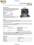
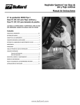
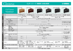
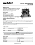
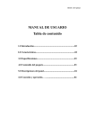
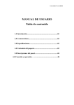
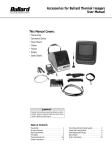
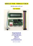
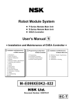
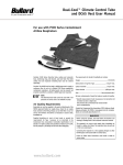
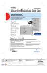
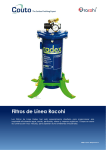
41 Series Airline Filters
User Manual
TM
Bullard airline filters can be used in conjunction with
other compressor safeguards to supply cleaner air to
airline respirators. They can also be used to supply drier,
cleaner air to pneumatic tools and systems. Bullard
airline filters will not remove carbon monoxide
and other toxic gases from the airline.
Specification G7.1 (Grade D or higher), as specified
by federal law 42 CFR, Part 84, Subpart J,
84.141(b). The Bullard airline filter does not
remove carbon monoxide and other toxic gases
from the air being supplied. The requirements for
Grade D breathable air include:
Set-Up
• Oxygen . . . . . . . . . . . . . . . . . . . . . . 19.5 - 23.0%
1. Location:
Select a flat, stable location to mount the filter. Bolt
the filter in position using the mounting legs. If wall
mounting is desired, use the Model 41P6WM, which is
designed with a wall-mount bracket.
• Hydrocarbons (condensed). . . . . . 5 mg/m3 max.
• Carbon Monoxide . . . . . . . . . . . . . . 10 ppm max.
• Carbon Dioxide . . . . . . . . . . . . . . 1000 ppm max.
• No toxic contaminants at levels which would
make the air unsafe to breathe.
WARNING
Refer to the C.G.A. Commodity Specifications G7.1
for complete details. It is available from:
Compressed Gas Association, 1235 Jefferson Davis
Highway, Arlington, VA 22202.
Filter must be mounted securely on a suitable base to
prevent tipping over during use. Failure to follow this
instruction could result in death or serious injury.
2. Connection:
Connect compressor hose to the air inlet. Connect the
respirator or pneumatic tool airline hose to the filter
outlet. Tighten the connections to prevent leaks and
possible pressure loss.
WARNING
When using a respirator, do not connect the filter to
any air source unless you are certain it supplies
breathable air. Failure to ensure breathable air source
could result in death or serious injury.
Operation
1. Air Requirements
a. Air Source Monitoring:
Federal Law requires use of carbon monoxide and
high temperature monitors or alarms when oil
lubricated compressors are used as sources of
breathing air. If only a high temperature alarm is
used, you must frequently test the compressor air
for carbon monoxide to ensure it meets the Grade
D requirements discussed below.
The law also requires that breathing air hose
couplings be incompatible with outlets for other
gas systems in order to prevent accidental
connection of a supplied air respirator to nonrespirable gases or oxygen.
c. Air Pressure:
The air pressure at the filter inlet should not
exceed 100 psig (6.89 bar). Air will be released by
the pressure relief valve when pressure within the
filter exceeds 125 psig (8.6 bar). Air discharging
from the filter can be controlled to meet specific air
pressure requirements by using the pressure
regulator adjustment knob. Refer to your respirator
or pneumatic tool instruction manual to find the
appropriate air pressures required for correct use
of the equipment.
d. Temperature:
Air supplied to the filter should not exceed 140° F
(60° C). Therefore, do not connect the filter directly
to the compressor exhaust manifold.
2. Correct Operation Procedures
a. Drain accumulated water and oil from the filter
tank as required by opening the petcock drain
valve. Normally the tank will need to be drained at
least once a day. In humid climates, or if large
amounts of water and oil are present in the air
supply, drain the filter tank more often.
b. Tighten the fasteners which secure the head to
the filter tank. Over time, the fasteners may loosen
which could cause a leak in the air system.
(Recommended tightness is 20 ft. lbs.)
b. Quality of Breathing Air:
Supplied breathing air passing through this filter to
a respirator must meet at least the requirements
for Type 1 gaseous air as described in the
Compressed Gas Association Commodity
Refer to figure 1 on page 2 of these instructions
for set-up and operation.
WARNING
The 41 Series Airline filters do not remove carbon monoxide and other toxic gases. Review and observe all pertinent
federal and state safety regulations in conjunction with airline respirators. Failure to observe safety regulations or
improper use of Bullard Airline Filters could result in death or serious injury.
TM
Cartridge Replacement
WARNING
Use only Bullard 41AF cartridges as replacements.
Bullard Model 41 Series Airline Filters are designed to
use only Bullard filter cartridges. Failure to use the
correct filter cartridge could result in death or serious
injury.
The frequency of filter cartridge replacement depends on
the conditions of the particular air system in which the
filter is installed. However, the filter cartridge should be
replaced immediately if:
a. The user smells or tastes contaminants in the air
being supplied to an air-supplied respirator, or;
b. There is a large pressure drop in the system, even
though the compressor and other components
appear to be operating correctly.
Corrective Action
1. Shut off air supply and drain filter as described on the
reverse side of this instruction sheet. Disconnect the
filter from the air source before servicing.
2. Replace the Cartridge:
a. Separate the filter head from the tank by removing
the fasteners.
b. After removing the cartridge, clean the inside of the
tank to remove any remaining contaminants.
c. Insert a new Bullard Model 41AF filter cartridge.
Tighten the fasteners across from each other and
not in a circular sequence. This will help prevent
warping of the filter head.
1/4" (6 mm) Outlets
(not shown)
3/8" Outlet (7 mm)
Outlet Air
Pressure Gauge
4. If conditions are not improved, do not use the filter
until appropriate corrective measures have been taken.
Replaceable Filter Cartridge 7-Stage Operation
Cartridges effectively trap and remove impurities with
little pressure loss. The supplied-air enters the filter at
inlet connector (A), travels through 6 layers of filter
material and exits at outlet connector (B) (refer to figure
2). Filter materials work in sequence to trap and hold
water, oil, particulates, odors, and organic vapors so that
cleaner air is delivered to workers or equipment.
1. Water is removed by condensation of air in outer
cylinder.
2. Carded cotton removes particulates.
3. Activated alumina adsorbs oil and moisture.
4. Activated charcoal removes odors and moisture.
5. Felt material removes particulates.
6. Carded cotton removes particulates.
7. Respiratory felt at final stage acts as a final filter
before air is transferred to worker or air driven tools.
WARNING
Filter cartridge must be changed periodically for
maximum efficiency. Frequency of cartridge changes
depends on operating conditions. Cartridge should be
changed immediately if respirator wearer feels, smells or
tastes contaminants inside the respirator. Filter tank
should be drained at least daily to remove trapped water
and oil (a petcock is provided on the bottom of the tank
for this purpose). Failure to follow these instructions
could result in death or serious injury.
Outlet
Connector
(B)
Pressure Regulator
Adjustment Knob
Pressure Relief Valve
Fasteners
(securing filter
tank to the head)
(A Model 41P2 is
diagrammed for
illustration purposes.)
3. Record the date the filter was replaced on the label
attached to the airline filter tank. You can develop a
filter cartridge replacement schedule by monitoring the
frequency with which the cartridge needs to be
changed.
Air Inlet (1" NPT-FEM) (25 mm)
Inlet
Connector
(A)
Legs
(with mounting
capabilities)
Drain Petcock
Figure 1
Figure 2
1898 Safety Way • Cynthiana, KY 41031-9303 • Toll free: 877-BULLARD (285-5273) • Tel: 859-234-6616 • Fax: 859-234-8987 • www.bullard.com
41 Series Airline Filters
User Manual
Bullard 41EAK European Adapter Kit
The Bullard 41EAK European Adapter Kit is supplied to
accommodate the threaded coupling and fitting
requirements and standards of Europe.
This Kit contains:
1 ea. 1" (25 mm) X 3/4" (19 mm) pipe reducing bushing
2 ea. 1/4" (6 mm) MPT British thread adapter
1 ea. 3/8" (7 mm) X 1/4" (6 mm) reducing bushing
Installing Adapters:
• Apply thread sealant to the 1/4" (6 mm) MPT British
Thread adapter.
• Install the 1/4" (6 mm) MPT British Thread adapter into
the open port (refer to figure 4 below).
• Tighten with a wrench until wrench tight.
3. If a second air outlet is required.
• Locate the 3/8" (7 mm) X 1/4" (6 mm) MPT bushing and
the 1/4" (6 mm) MPT British Thread adapter in the
41EAK Kit bag.
1. Before using 41P2E filter:
• Remove the existing pipe plug from the TOP of the top
mounted regulator, using a wrench.
• Locate the 1" (25 mm) X 3/4" (19 mm) Pipe Reducing
Bushing in the 41EAK Kit bag.
• Apply thread sealant to the 3/8" (7 mm) X 1/4" (6 mm)
MPT bushing.
• Apply thread sealant to the 1" (25 mm) X 3/4" (19 mm)
Pipe Reducing Bushing.
• Install the 3/8" (7 mm) X 1/4" (6 mm) MPT bushing into
the open port (refer to figure 5 below).
• Install the 1" (25 mm) X 3/4" (19 mm) Pipe Reducing
Bushing into the air inlet on side of filter (refer to figure
3 below).
• Tighten with a wrench until wrench tight.
• Tighten with a wrench until wrench tight.
2. If only one air outlet is required:
• Locate the 1/4" (6 mm) MPT British Thread adapter in
the 41EAK Kit bag.
• Remove the existing pipe-to-hose adapter from
the SIDE of the top mounted regulator, using a wrench.
• Apply thread sealant to the 1/4" (6 mm) MPT British
thread adapter.
• Install the 1/4" (6 mm) MPT British Thread adapter into
the open end of the 3/8" (7 mm) X 1/4" (6 mm) bushing
that was installed in the step above (refer to figure 6
below).
• Tighten with a wrench until wrench tight.
Figure 3
Figure 4
Figure 5
Figure 6
1898 Safety Way • Cynthiana, KY 41031-9303 • Toll free: 877-BULLARD (285-5273) • Tel: 859-234-6616 • Fax: 859-234-8987 • www.bullard.com
TM
Head
Protection
Respiratory
Protection
Fire and Rescue
Safety
Thermal
Imaging
Specifications
Airline Filter
Model 41A
Model 41P6
Model 41P6WM
Model 41P2E
Max. Air Flow Rate
100 cfm* (2830 lpm) 75 cfm (2120 lpm)
75 cfm (2120 lpm)
75 CFM (2120 lpm)
75 cfm (2120 lpm)
Inlet Connection
1" NPT (Fem.)
1" NPT (Fem.)
1" NPT (Fem.)
3
2 outlets ⁄4" &
3
⁄8" NPT (Fem.)
6 outlets
3
⁄8" NPT (Fem.)
6 outlets
3
⁄8" NPT (Fem.)
2 outlets
1
⁄4" (6 mm) BPT (Fem.)
125 psig (8.6 bar)
125 psig (8.6 bar)
125 psig (8.6 bar)
125 psig (8.6 bar)
Outlet Connection
1" NPT (Fem.)
Relief Valve
–
Model 41P2
1" NPT (Fem.)
1
⁄4" (19 mm) NPT (Fem.)
Tank Diameter
51⁄2" (14 cm)
51⁄2" (14 cm)
51⁄2" (14 cm)
51⁄2" (14 cm)
51⁄2" (14 cm)
Height
19" (48 cm)
231⁄2" (60 cm)
25 1⁄4" (64 cm)
22" (56 cm)
231⁄2" (60 cm)
Weight
19 lb. (8.6 kg)
22 lb. (10 kg)
24 lb. (10.9 kg)
28 lb. (12.7 kg)
22 lb. (10 kg)
*At maximum recommended pressure of 100 psig (6.9 bar)
Ordering Information
CATALOG
NUMBER
CATALOG
NUMBER
DESCRIPTION
DESCRIPTION
Replacement Parts
41A
Single-outlet filter. Pressure gauge, relief
valve, and pressure regulator not included
41AF
Replacement filter cartridge
41P6UPK
41P2
2-outlet filter with pressure gauge, relief
valve, pressure regulator, and hose adapter
fitting
6-outlet manifold upgrade (includes
manifold, regulator assembly, relief valve,
and gauge) for 41P6
41P2M
41P6
6-outlet filter with pressure gauge, relief
valve, pressure regulator, and hose adapter
fitting
2-outlet manifold assembly (includes
manifold with regulator, relief valve and
gauge) for 41P2 and 41P2E
41PRV
41P6WM
6-outlet filter with wall-mount bracket,
pressure gauge, relief valve, pressure
regulator, and hose adapter fitting.
Pressure Relief Valve for 41P2, 41P2E,
and 41P6/41P6WM airline filters. Set at
125 psig (8.6 bar).
41RG
41P2E
2-outlet filter with pressure gauge, relief
valve, pressure regulator, and hose adapter
fitting, plus adapters suitable for European
threaded connections
Regulator Gauge for 41P2, 41P2E, and 41P6
airline filters
41P2R
41P2 regulator and assembly (For use with
flat top design only)
41EAK
European adapter kit for 41P2E containing
(1) 1" (25 mm) x 3⁄4 " (19 mm) Pipe Reducing
Bushing,
(1) 3⁄8" (7 mm) x 1⁄4" (6 mm) Reducing
Bushing and
(2) 1⁄4" (6 mm) MPT British Thread Adapters.
9 0 01
ifi
ed
IS O
Bullard Airline Filters
Ce
rt
ISO 9001
certified
Bullard
1898 Safety Way
Cynthiana, KY 41031-9303
Toll free: 877-BULLARD (285-5273)
Tel: 859-234-6616
Fax: 859-234-8987
www.bullard.com
Bullard GmbH
Hochkreuzallee 36
53175 Bonn-Bad Godesberg
Germany
Tel: +49 228 931933 0
Fax: +49 228 931933 50
©2001 Bullard. All rights reserved, including the right of
reproduction, in whole or in part, in any form.
“It’s your life and you’re worth it” is a trademark of
Bullard.
6091100067 (0701)