Download - KMT Telemetry
Transcript
KMT - Kraus Messtechnik GmbH Gewerbering 9, D-83624 Otterfing, Germany, 08024-48737, Fax. 08024-5532 Home Page: http://www.kmt-telemetry.com, Email: [email protected] TEL1-PCM-HS-BATT User Manual Digital High Data Rate Telemetry System for Strain Gage and ICP Applications on Rotating Shafts “Gain and Auto Zero setting direct from Receiver Side!” ICP current 4mA, Gain selectable to: 2-4-8-16 For strain gages or IPC sensors Digital transmission realized inductively Strain gage sensors (>350 Ohm) Distance up to 50mm Full- and half bridge configuration No influence through radio frequency Excitation fixed 4 Volt DC Many systems can operated at the same time Auto-Zero adjustment - Setting receiver side Signal bandwidth 0…50kHz (Scanning rate 104kHz) Gain: 250-8000 - Setting receiver side Output +/-10V and digital for interface (Option) External shunt calibration System accuracy <0.2% INSTRUCTIONS FOR QUALIFIED PERSONNEL ONLY! Easy to assemble and operate General Description The TEL1-PCM-HS-BATT single-channel high data rate telemetry system offers the easiest handling for the wireless transmission of strain gage signals from rotating shafts. The encoder 62x27x13mm with a weight of 30g. The transmitter (encoder) part is simply mounted on the rotating shaft with a special fiber reinforced tape. Powering of the transmission part is via battery 6-9V or optional inductive power supply. The digital data transfer between transmitter and receiver is realized inductively. Functional Description The TEL1-PCM-HS-BATT transmitter provides a pulse code modulated signal (PCM) to an induction winding around the shaft (max. diameter 500mm, other on request!). The magnetic field of this winding enables the inductive transmission of the signal to the pickup coil. From there the signal is transferred by cable (5 m) to the receiver. The maximum distance between the transmitter coil and the pickup is 50mm. (with standard head) The receiver unit offers a BNC connector at the front panel with analog outputs 10 V and a optional a digital output for PCM interface ECIA100 (for notebooks) or IF16 (PCI Desktop). An LED bar indicator shows the actual level and a successful Auto Zero calibration. Overload is indicated by the last LED´s in pos. or neg. direction of the bar graph. These OVL-LED´s operate in peak-hold mode and are reset by pressing the overload switch. Strain gage sensors (>350 Ohm) in full- and half- bridge configuration can be directly connected to the transmitter. The excitation is fixed to 4 Volt DC and the gain is set by the gain switch on the receiver side. An auto-zero (AZ) adjustment is executed by pressing the AZ button on the front side of the receiver. The successful AZ operation is indicated by a yellow LED in the middle of the LED bar indicator. When the AZ completes the LED continuously illuminates. A continued flashing of the yellow LED indicates some error in the AZ electronics. In this case please contact the support of KMT. Additional to the AZ you have the possibility to calibrate the bridge by external shunt. (+ and -). The AZ setting is stored in a Flash-RAM and thus is not lost during power-off. Use only shielded sensor cable. TEL1-PCM-HS-BATT set contains: Inductive Pickup with 5m cable TEL1-PCM-HS-BATT-DEC (Decoder) Mounting tape 25mm and 50mm Length 50meter Ferrite tape 30mm x 3 meter (isolate magnetic field between shaft and coil) CU wire, 0.5mm for coil (insulated with lacquer) TEL1-PCM-HS-STG-(BATT) DC-Power cable Version 2012-10 (Encoder for strain gages) 2 6V Lithium battery Hexagon key to activate the OLV and AZ switch Screw driver to set the gain Technical Data are subject to change without notice! Technical Data - rotating part TEL1-PCM-HS-BATT-STG Strain gage: Full and 1/2 bridge >350 Ohm, Excitation: 4 VDC (fixed) Gain: 250; 500; 1000; 2000; 4000; 8000 (selectable from receiver side) Sensitivity STG Module Input vs Decoder Output Gain 250 = 4mV/V Gain 500 = 2mV/V Gain 1000 = 1.0mV/V Gain 2000 = 0.500mV/V Gain 4000 = 0.250mV/V Gain 8000 = 0.125 mV/V The max. output is +/-10V Shunt Cal: Via external resistor for positive and negative calibration AZ: Auto Zero calibration (selectable from receiver side) Analog signal bandwidth: 0 - 50 kHz (-3 dB) Sampling rate 104 kHz Operating temperature: - 10 to + 80 °C Dimensions: 62 x 27 x 13mm (without connectors) Weight: each module 30 grams Static acceleration: up to 3000g Powering: Battery 6-9V, Power consumption 70mA at 6V Optional additional inductive powering TEL1-PCM-HS-BATT-ICP For all ICP sensors Curren: 4mA (fixed) Gain: 1; 2; 4; 8; 16; 32 (selectable from receiver side) Gain Resolution 250 = 1 at ICP 12 bit 500 = 2 at ICP 12 bit 1000 = 4 at ICP 12 bit 2000 = 8 at ICP 12 bit 4000 = 16 at ICP 12 bit 8000 = 32 at ICP 11 bit Analog signal bandwidth: 3 - 50000 (-3 dB) Sampling rate 104 kHz Operating temperature: - 10 to + 80 °C Dimensions: 62 x 27 x 13mm (without connectors) Weight: each module 30 grams Static acceleration: up to 3000g Powering: Battery 6-9V, current consumption 80mA at 6V Optional additional inductive powering Version 2012-10 3 Technical Data are subject to change without notice! Technical Data - static part Front Version 2012-10 Rear TEL1-PCM-HS-BATT-DEC Front side: Analogue output: +/-10V via BNC Digital output for PCM Interface IF16 (ECIA100) OPTION Gain setting : via screw switch Auto Zero setting: via micro switch Overload LED’s (Red ON) reset: via micro switch Green LED’s: Bargraph +/Autozero LED: Yellow ON- successful AZ Yellow OFF- not successful AZ if flashing, call support of KMT, error in EPROM Green LED’s: Bargraph +/SL LED: Red ON = if error of data transmitting SL LED: Red Flashing = if distance to far Power ON LED: Red ON = if power switch on Rear side: Output to Powerhead: via 5pol. Tuchel Fuse LED: Flashing if fuse is defect Powering: 10-30V DC, Input via 7pol. Tuchel Switch: ON/OFF Operating temperature: - 10 to +70 °C Dimensions: 200 x 105 x 44 (without connectors!) Weight 950 grams Static acceleration: up to 200g System accuracy (without sensor): +/- 0.2 % TEL1-PCM-HS-Pickup Function: Receiving inductive magnetic field in PCM modulated code Distance between the transmitter coil and the pickup is 50mm Output to TEL1-PCM-HS-BATT Decoder via 5pol. Tuchel plug incl. 5m cable. Cable length standard 5m, optional 20m Operating temperature: - 10 to +80 °C Dimensions: 45x60x25mm (without cable) Weight: 400 grams (with 5m cable!) Housing: splash-water resistant IP65 (except connector). 4 Technical Data are subject to change without notice! Transmitting Part: Strain gage connection The pins for battery +6-9V and GND Battery Version 2012-10 5 Coil connection Inductive coil Technical Data are subject to change without notice! Block diagram: Note: The Powerhead must be fixed in the middle of the coil in a distance from 5 up to 50 mm. Version 2012-10 6 Technical Data are subject to change without notice! Receiving Part: Front Positive Baragraph LED With overload indicator Auto Zero LED ON = successful OFF = Not successful Analog output +/-10V Gain switch Negative Bargraph LED With overload indicator Reset button of overload indicator AZ button LED ON = Error data transmission LED Flashing = Battery voltage lower 6V Power On LED Rear Flashing if fuse damage Data input from Pickup head PCM OUT for Interface (Option!) Power In DC 10 – 30V Power ON/OFF switch Version 2012-10 7 Technical Data are subject to change without notice! Pin connection cable: Pickup Distance of 5-100mm DC-Power cable Version 2012-10 8 Technical Data are subject to change without notice! Shaft Installation Fix with 2 layers of mounting tape around the shaft Mount 2 layers of the special ferrite tape around the shaft. (each layer seperatly, without overlap!) 1.) 2.) Coil, depends of shaft diameter 4-25 parallel windings of 0.5 CUL wires (see table for help) 4.) 3.) Fix with 3-4 layers of mounting tape around the shaft 5.) Version 2012-10 6.) 9 Technical Data are subject to change without notice! Solder the wires of the coil on the pins of TEL1PCM-HS-STG “2x Coil” 7.) 8.) 10 layers of the special mounting tape (width 50mm) around the shaft. We recommend add. use a steel hose clamp for final fixing!! 9.) 10.) steel hose clamps Caution: Fix TEL1-PCM-HS-STG-BATT module with at least 10 layers (width 50mm) of the special mounting tape around the shaft. Depending on the shafts RPM and diameter particular attention needs to be paid to the safe mounting of the components. The manufacturer doesn’t accept liability for damages, which results from insufficient attachment of the individual components. The tape is only for test purposes, in order to test the electrical function of the units in the idle state of the shaft. During the rotation test appropriate safety precautions should be taken. The entire installation may be used only by authorized persons. By using tape for the attachment, it has to be used in the direction of rotation of the shaft and the end has to be secured. Only non-elastic tapes with high tensile strength should be used for pre-fixing. Additionally, use a steel hose clamp for final fixing!! The individual components are to be distributed in such a way on the shaft that imbalances are avoided. Version 2012-10 10 Technical Data are subject to change without notice! Find the correct amount of windings The number of windings depends on several factors. The most important influential factors are the diameter, the materiel of the shaft and the environment around the shaft. The table standing below will help you to find the right number windings for steel shafts. The table below is a help to estimate the number of windings fast. To optimize your results you can try one winding more or less. Coil, depends of shaft diameter 4-25 parallel windings of 0.5 CUL wire Optimum windings for steel shafts 600 diameter 500 400 300 200 100 0 0 2 4 6 8 10 12 14 windings Windings Diameter (mm) 8 8 9 10 11 12 13 600 500 250 125 80 40 20 Version 2012-10 11 Technical Data are subject to change without notice! Kraus Messtechnik GmbH Gewerbering 9, D-83624 Otterfing, +49-8024-48737, Fax. +49-8024-5532 – Germany Home Page http://www.kmt-gmbh.com Email: [email protected] Konformitätserklärung Declaration of Conformity Declaration de Conformité Wir We Nous KMT - Kraus Messtechnik GmbH Anschrift Address Adress Gewerbering 9, D-83624 Otterfing, Germany erklären in alleiniger Verantwortung, daß das Produkt declare under our sole responsibility, that the product declarons sous notre seule responsibilité, que le produit Bezeichnung Name Nom Messdatenübertragungssystem Typ,Modell,Artikel-Nr., Größe Type,Model, Article No.,Taille Type, Modèle, Mo.d'Article,Taille TEL1-PCM-HS-BATT mit den Anforderungen der Normen und Richtlinien fulfills the requirements of the standard and regulations of the Directive satisfait aux exigences des normes et directives 108/2004/EG Elektromagnetische Verträglichkeit EMV / EMC DIN EN 61000-6-3 Ausgabe 2002-8 Elektromagnetische Verträglichkeit EMV Teil 6-3 Fachgrundnorm Störaussendung DIN EN 61000-6-1 Ausgabe 2002-8 Elektromagnetische Verträglichkeit EMV Teil 6-1 Fachgrundnorm Störfestigkeit und den angezogenen Prüfberichten übereinstimmt und damit den Bestimmungen entspricht. and the taken test reports und therefore corresponds to the regulations of the Directive et les rapports d'essais notifiés et, ainsi, correspond aux règlement de la Directive. Otterfing, 27.04.2006 Martin Kraus Ort und Datum der Ausstellung Place and Date of Issua Lieu et date d'établissement Name und Unterschrift des Befugten Name and Signature of authorized person Nom et signature de la personne autorisée Version 2012-10 12 Technical Data are subject to change without notice! KMT - Kraus Messtechnik GmbH Gewerbering 9, D-83624 Otterfing, Germany, 08024-48737, Fax. 08024-5532 Home Page http://www.kmt-gmbh.com, Email: [email protected] Inductive power supply Assembling instructions for TEL1-PCM-HS-BATT Version 2012-10 13 Technical Data are subject to change without notice! Inductive power supply set Picture shows standard Inductive Power Supply for diameter up to 300mm Power supply for power head DC Power cable 25 and 50mm mounting tape to fix coil on shaft IND-PWR AC/DC module Input: AC from coil Output 6.5VDC 100mA Ferrite tape 30mmx3m CU wire 0.5mm Power Head with cable Mounted on shaft Version 2012-10 14 Technical Data are subject to change without notice! Installation of coil for inductive powering on shaft Attach for electromagnetic insulation “Ferrite Tape” - 2 x layers Ferrite-Tape around the shaft - Fixed with 2 layers mounting tape Wind the 0.5 mm enameled copper wire around the shaft: - 4-25 windings for 500-20mm diameter Other diameter on request! Note: “The inductive load of the IND-PWR AC/DC module and the capacitor in the Power Head must be in resonance to get the optimal transmission. The inductive load of the shaft depends of diameters, material and number of windings. ” To find the optimal transmission try one winding more ore less. The LED on the Inductive Power module will help to find the best configuration. The distance between powerhead and the coil is 3-10mm. Control the output voltage and move the powerhead in the max distance to the coil. The minimum Output voltage must be 6,5 V! Fix all with 2-3 layers around the coil with mounting tape. Version 2012-10 15 Technical Data are subject to change without notice! Optimum windings for steel shafts 1200 Diameter mm 1000 800 600 400 200 0 0 5 10 15 20 25 30 Windings Diameter (mm) Windings 1000 490 290 190 150 120 80 45 4-5 4-5 5 7 9 10 12 16 20 25 Fine adjustment capacitor parallel to coil 100-200nF (Type MKT or MKS 250V) 100-200nF (Type MKT or MKS 250V) 100-200nF (Type MKT or MKS 250V) ------------- We recommend a capacitor decade e.g 100pF .... 11,111 µF 100-200nF Magnetic field Version 2012-10 16 Technical Data are subject to change without notice! Control LED The pins “AC IN” are the AC power input from the coil. On the pins “+6.5” and “GND“ you get a stabilized output voltage of 6.5V DC. The control LED will lights up, as soon as the power head is switched on and at the right position - close enough to the coil on the shaft. The max. load current on the DC output is 100mA. The AC/DC converter will use instead battery pack! AC IN 6,5 DC OUT Never use any battery together with the IndPwr!´ Installation of the power head for inductive powering Power head IND-PWR AC/DC module Power supply for power head Connect the power head on the “AC Out” socket of the power box and then the DC power cable on the “DC In 10-30V” socket. The two banana plugs have to be connected to a DC power source with red on +10-30V DC and black on 0V. Inductive coil You should mount the power head at a fixed location that it’s as free as possible from vibration influences. The center of the coil should be in the same horizontal position as the center of the power head. The distance is optimal in the range between 3 and 10mm. (depends of shaft and current consumption) If the red LED of the AC/DC converter lights up, the position of the power head is OK. Power head Version 2012-10 17 Technical Data are subject to change without notice! Fixing of IND-PWR AC/DC module and TEL1-PCM-HS-BATT Fix all modules with at least 10 layers of the special mounting tape around the shaft. According to the shafts RPM and diameter it’s particularly paid attention to safe mounting of the components. Add. use hose clamps for final fixing!! The manufacturer doesn’t accept liability for damages, which results from not sufficiently attachment of the individual components. The provided cable harness and the tape are only for test purposes, in order to test the electrical function of the units in the idle state of the shaft. During the rotation test appropriate safety tools are to be attached. The entire installation may be used only by authorized persons. By using tape for the attachment, it has to be used in the direction of rotation of the shaft and the end has to be secured against removing. Only non-elastic tapes with high tensile strength have to be used for pre-fixing. Add. use hose clamps for final fixing!! The individual components are to be distributed in such a way on the shaft that imbalances will avoid. Connection IND-PWR AC/DC module and TEL1-PCM-HS-BATT To avoid transmitting error, the mounting distance between Inductive Power Head and Inductive Pickup Head must be at least 100mm. Version 2012-10 18 Technical Data are subject to change without notice! Following must be considered at the mounting of the inductive power head Shaft with Cu wire Coil Magnetic field 25-30mm Don’t use for mounting any kind metal in this area (25-30mm)! Otherwise flow magnetic energy in the metal also and degrease the distance between power head and coil (on shaft)! Example of mounting plate, Wrong!!! Mounting plate cover the active area of inductive head Version 2012-10 19 Technical Data are subject to change without notice! 
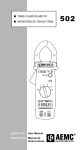
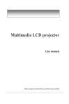
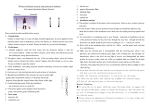
Dimensions Powerhead 66 Drill d= 4,3mm 33 30 10 Cable length 5m 43 Optional 10...20m 53 33mm 66 Version 2012-10 20 Technical Data are subject to change without notice! Attention Use only shielded sensor cable When used on rotating shafts, all connections must be soldered. Mounting of the modules on a shaft must be first fixed with mounting tape (only for prefixing) and then with a hose clamps!!! Safety Notes for Inductive Powering The device should only applied by instructed personnel. The power head emits strong magnetic radiation at 60 kHz to a distance of 20 cm. Therefore persons with cardiac pacemakers should not work with this device! Magnetic data storage media should be kept in a distance of at least 3m from the power head to avoid data loss. The same is valid for electromagnetic sensitive parts, devices and systems. Do not place the power head in the switched-on state on metallic objects, because this results in eddy currents, which could overload the device and strongly heat up small objects. In addition, the probe could be destroyed! No metallic objects, other than the disc-type coil, should be located in the air gap of the power head. The same applies to metallic parts within a radius of up to 15–20 mm in all directions. Do not use damaged or faulty cables! Never touch in the area between shaft and inductive head, the rotating shaft itself or rotor electronic contacts during operation! This is a “Class A” system suitable for operation in a laboratory or industrial environment. The system can cause electromagnetic interference when used in residential areas or environments. In this case the operator is responsible for establishing protective procedures. Version 2012-10 21 Technical Data are subject to change without notice!