1
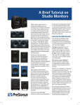
Published by:
Stage Accompany B.V.
Training & Documentation
Anodeweg 4
1627 LJ Hoorn, The Netherlands
Copyright © 1989 by Stage Accompany B.V.
All rights reserved. No part of this manual may be reproduced or transmitted in any form or by
any means, electronic or mechanical, without written permission from Stage Accompany, except
for the inclusion of brief quotations in a review.
First Printing, September 1989
Printed in The Netherlands
This manual is designed to provide information about the PPA 1200. Every effort has been
made to make this manual complete and as accurate as possible. But no warranty of suitability,
purpose, or fitness is implied. The information is provided on an “as-is” basis. Stage Accompany
shall have neither liability nor responsibility to any person or entity with respect to any loss or
damages in connection with or arising from the information contained in this manual.
IBM is a registered trademark of International Business Machines Corporation.
Stage Accompany PPA 1200
Programmable Power Amplifier
User Manual
Published by:
Stage Accompany B.V.
Training & Documentation
Anodeweg 4
1627 LJ Hoorn, The Netherlands
Copyright © 1989 by Stage Accompany B.V.
All rights reserved. No part of this manual may be reproduced or transmitted in any form or by
any means, electronic or mechanical, without written permission from Stage Accompany, except
for the inclusion of brief quotations in a review.
First Printing, September 1989
Printed in The Netherlands
This manual is designed to provide information about the PPA 1200. Every effort has been
made to make this manual complete and as accurate as possible. But no warranty of suitability,
purpose, or fitness is implied. The information is provided on an “as-is” basis. Stage Accompany
shall have neither liability nor responsibility to any person or entity with respect to any loss or
damages in connection with or arising from the information contained in this manual.
IBM is a registered trademark of International Business Machines Corporation.
Table of Contents
Quick Introduction to the PPA 1200
Introduction
Connections
Operation
Indicators
Recommendations for optimum Use of the PPA 1200
Technical Specifications
Trouble Shooting
Table Of Contents
1
Quick Introduction to the PPA 1200. . . . . . . . . . . . . . . . . . . . . . . . . . . . . .
1-1
2
Introduction . . . . . . . . . . . . . . . . . . . . . . . . . . . . . . . . . . . . . . . . . . . . . . . . .
2-1
3
Connection of the PPA 1200 . . . . . . . . . . . . . . . . . . . . . . . . . . . . . . . . . . . .
3-1
3-1
Mains Power. . . . . . . . . . . . . . . . . . . . . . . . . . . . . . . . . . . . . . . . . . . . .
3-1
3.2
Audio Connections . . . . . . . . . . . . . . . . . . . . . . . . . . . . . . . . . . . . . . . .
3-8
3.3
Loudspeaker Connections . . . . . . . . . . . . . . . . . . . . . . . . . . . . . . . . . .
3-8
3.4
SAnet Connections. . . . . . . . . . . . . . . . . . . . . . . . . . . . . . . . . . . . . . . . 3-16
4
Operation . . . . . . . . . . . . . . . . . . . . . . . . . . . . . . . . . . . . . . . . . . . . . . . . . . .
4-1
4.1
Readout Select . . . . . . . . . . . . . . . . . . . . . . . . . . . . . . . . . . . . . . . . . . .
4-1
4.2
Level . . . . . . . . . . . . . . . . . . . . . . . . . . . . . . . . . . . . . . . . . . . . . . . . . . .
4-1
4.3
Maximum Power and Active Crossover Presets. . . . . . . . . . . . . . . . . .
4-1
4.4
Power Amp On Delay . . . . . . . . . . . . . . . . . . . . . . . . . . . . . . . . . . . . . .
4-3
4.5
Channel Mode . . . . . . . . . . . . . . . . . . . . . . . . . . . . . . . . . . . . . . . . . . .
4-3
4.6
System Ground Lift . . . . . . . . . . . . . . . . . . . . . . . . . . . . . . . . . . . . . . . .
4-4
4.7
SAnet Ground Lift . . . . . . . . . . . . . . . . . . . . . . . . . . . . . . . . . . . . . . . . .
4-5
4.8
Input Ground Lift. . . . . . . . . . . . . . . . . . . . . . . . . . . . . . . . . . . . . . . . . .
4-5
4.9
System Lock/Unlock . . . . . . . . . . . . . . . . . . . . . . . . . . . . . . . . . . . . . . .
4-5
4.10
Bridge Mode . . . . . . . . . . . . . . . . . . . . . . . . . . . . . . . . . . . . . . . . . . . . .
4-6
4.11
Software Version . . . . . . . . . . . . . . . . . . . . . . . . . . . . . . . . . . . . . . . . .
4-6
4.12
ID Code . . . . . . . . . . . . . . . . . . . . . . . . . . . . . . . . . . . . . . . . . . . . . . . .
4-6
4.13
Signal Present Time . . . . . . . . . . . . . . . . . . . . . . . . . . . . . . . . . . . . . . .
4-7
4.14
Power Amplifier On Time . . . . . . . . . . . . . . . . . . . . . . . . . . . . . . . . . . .
4-8
4.15
Activating the “boot” mode . . . . . . . . . . . . . . . . . . . . . . . . . . . . . . . . . .
4-8
Indicators . . . . . . . . . . . . . . . . . . . . . . . . . . . . . . . . . . . . . . . . . . . . . . . . . . .
5-1
5.1
Input Signal Present . . . . . . . . . . . . . . . . . . . . . . . . . . . . . . . . . . . . . . .
5-1
5.2
Clipping of the Amplifier . . . . . . . . . . . . . . . . . . . . . . . . . . . . . . . . . . . .
5-1
5.3
Power Limiting . . . . . . . . . . . . . . . . . . . . . . . . . . . . . . . . . . . . . . . . . . .
5-1
5.4
DC Protection of the Amplifier . . . . . . . . . . . . . . . . . . . . . . . . . . . . . . .
5-2
5.5
Overheated Amplifier . . . . . . . . . . . . . . . . . . . . . . . . . . . . . . . . . . . . . .
5-2
5.6
High Power Fuse Blown . . . . . . . . . . . . . . . . . . . . . . . . . . . . . . . . . . . .
5-2
5
6
Recommendations for Optimum Use. . . . . . . . . . . . . . . . . . . . . . . . . . . . .
6-1
7
PPA 1200 Specifications . . . . . . . . . . . . . . . . . . . . . . . . . . . . . . . . . . . . . . .
7-1
8
Security Function . . . . . . . . . . . . . . . . . . . . . . . . . . . . . . . . . . . . . . . . . . . .
8-1
Resetting the System Lock and Lock Code . . . . . . . . . . . . . . . . . . . . .
8-1
8.1
1-1
1 Quick Introduction to the PPA 1200
If you have to start using the PPA 1200 straight away and do not have time to read the complete
manual, make sure that you at least read the following:
• Ensure that you have a reliable, well earthed power source. The required current for
the PPA can be found in the table in paragraph 3.1.
• Connect the PPA to your signal sources via the <AUDIO IN> inputs. Connect this PPA
to other units via the <AUDIO OUT> outputs using short signal leads. Connect your
single signal source to the channel 1 input if you use the PPA in active crossover
mode or bridge mode.
IMPORTANT: Due to the fact that the low-frequency loudspeaker of the Blue Box has an polarity
opposite to that of the PPA/(all other SA loudspeakers) combination, the Blue Box has to be
switched to inverted phase or cross cables between PPAs and Blue Boxes have to be used!
• If computer control is desired, connect all PPAs with each other via <SANET IN> and
<SANET OUT>.
• Switch the PPA on using the <POWER ON/OFF> switch.
If you want to use the PPA in active crossover mode, use the <READOUT SELECT> key to
display the <MAXIMUM POWER>. The LED next to the word “Maximum power” will light up;
the displays register “900" (this is only true the first time the PPA is switched on or after a ”reset":
normally the last set values will be read from the memory).
• Press the <DOWN> key of channel 1 and keep it depressed. The value in the display
decreases from 900 to 30. Below 30 is a sequence of Stage Accompany loudspeaker
systems. Select the desired system using the channel 1 <UP> or <DOWN> key. An
overview of the various active crossover presets can be found in paragraph 4.3.
If you want to use the PPA in bridge mode, press the <BRIDGE MODE> key and keep it
depressed for at least 1 second until the channel 2 display and indications are disabled and the
<BRIDGE MODE> LED lights up. The bridged amplifier can now be controlled using the channel
1 controls.
• Switch both channels of the PPA from <STAND BY> (green LED lit) to <POWER
AMP ON> (red LED lit) using the <CHANNEL MODE> keys.
• Use the <READOUT SELECT> key to display the <LEVEL>. The LED next to the
word “Level” will light up; the displays register “OFF” (this is only true the first time the
PPA is switched on or after a “reset”: normally the last set values will be read from the
memory).
1-2
If the PPA is in active crossover mode, you do not have to adjust both low and high levels. They
are automatically set with the correct proportion when you select a loudspeaker system. In the
other modes, press both <UP> keys of channel 1 and channel 2 and keep them depressed.
The values in the displays increase from OFF, via -59 dB to 0 dB (completely open). However,
you may adjust the level of both amplifiers independently.
• Any earth hum that may be present may be cured with the <INPUT GROUND> keys,
the <SYSTEM GROUND> key, or (if connected) the <SA-NET GROUND> key.
• The use of the <SYSTEM LOCK> key is not directly necessary for the function of the
PPA. For further information, see paragraph 4.9.
The PPA 1200 is now ready for use.
2-1
2 Introduction
The Stage Accompany PPA 1200 is a dual channel high power microcomputer controlled
amplifier and comprises the following components:
• Balanced input stages.
• High and low pass filters per channel with 6-24 dB/octave slopes.
• Two amplifiers which each deliver 350 Watts RMS into 8 Ohms, 600 Watts RMS into 4
Ohms, and 900 Watts RMS into 2 Ohms.
• Microcomputer for control and protection of the unit.
• High speed computer interface (SAnet) for control via an IBM® (compatible) Personal
Computer.
Individual power supplies provide for an excellent channel separation and availability of the
maximum power at all times.
The functioning of the PPA is controlled and monitored by the built-in microcomputer. Via the
SAnet interface, the system can be controlled remotely by the Stage Accompany PC-AT or any
IBM (compatible) PC-AT. A maximum of 250 PPA 1200s can be controlled at distances of up
to 500 meters.
Note: The PPA performs excellently without a PC and/or interconnection via SAnet. The SAnet
interface is a standard provision that enables groupwise operation, but does not need to be
used.
The audio input and output are connected internally without electronics. This is done to prevent
any loss of quality. With an input impedance of 24 kohms, it is possible to connect a maximum
of 30 PPAs with each other. If more than 30 units need to be connected to each other, a separate
signal driver must be used.
The PPA is protected against the connection of speaker impedances less than 2 Ohms or even
shortcircuiting of the output. The output current is limited but the amplifier keeps working.
2-2
The PPA has a number of unique features, including:
• AEC, Auto Energy Control.
• DDC, Dynamic Damping Control.
• Built-in SA loudspeaker presets with crossover and protection.
• Temperature, peak and average output power readout.
• SAnet interface.
AEC
Auto Energy Control is a two-fold protection against clipping and overload at average power
and at peak power, which maintains the complete dynamic range of the signal. The microprocessor continuously measures the output power of the amplifier and monitors both the average
power and peak power. All levels are compared with the pre- and user-programmed values of
the AEC. As soon as an overload is detected, the volume is reduced in proportion to the amount
of overloading.
As soon as the cause of the overload has disappeared, the volume is gradually returned to its
original value. Attack and release times are independent of the type of overload and have been
chosen in such a way that a virtually inaudible operation is guaranteed.
DDC
Dynamic Damping Control is a special way of measuring the cone movement of a loudspeaker.
The voltage induced in the voicecoil is sensed and fed back to the amplifier’s feedback circuit.
Hence, a virtually infinite damping is achieved, which results in an exceptionally tight sound
reproduction.
Built-in SA-loudspeaker presets with crossover and protection
For optimum performance the PPA can be used in combination with a number of Stage
Accompany two and three way cabinets to form an active loudspeaker system. For this purpose,
the PPA has a built-in crossover and a number of so called crossover presets which are
programmed with predefined low and high levels and optimum protection parameters. The
crossover is always activated in preset mode in which channel 1 can be a low or midfrequency
amplifier and channel 2 a low or high frequency amplifier.
Temperature, peak and average output power readout
True peak and average output power are measured and displayed in Watts for each channel.
Furthermore the temperature of the power amplifier output semiconductors is displayed per
channel in degrees Celcius (°C).
2-3
SAnet Interface
The SAnet Interface is a computer interface developed by Stage Accompany that can be used
for monitoring and control of automated sound systems. Apparatus equipped with an SAnet
Interface (such as the Blue Box, PPA 1200 Programmable Amplifier and PPE 2410 Programmable Parametric Equalizer) can be connected to a Personal Computer, allowing remote
monitoring and control. All parameters of the individual units can be programmed and monitored
from the PC. Furthermore, the apparatus (such as PPAs) can be grouped as desired and then
controlled groupwise. The maximum communication distance, using the correct type of cable,
is 500 meters.
SAnet is a genuine communication system: data transfer occurs bi-directionally along the same
line. This is in contrast to (for example) MIDI. MIDI has separate in, out and thru provisions and
cabling, restricting communication to only one direction. The transmission speed of MIDI is
approximately 32 kB/s, that of SAnet is 375 kB/s, more than 10 times as fast!
SAnet and MIDI are not compatible!
For the application of SAnet, see paragraph 3.4 of this manual.
3-1
R
PPA 1200 USER MANUAL
stage accompany
3 Connection of the PPA 1200
Only three connections need to be made; mains power, audio input signals, and loudspeaker
leads. An SAnet connection is not necessary for normal (stand alone) functioning of the PPA.
3.1
Mains Power
PPA 1200
Mains
Supply
PPA 1200
PPA 1200
PPA 1200
OK
PPA 1200
PPA 1200
Figure 3-1. PPA 1200 connections to the mains supply.
Mains
Supply
CONNECTIONS
The PPA is set for 220 V / 50 Hz unless otherwise stated at the back of the amplifier. Always
ensure that you use a correctly grounded power supply. If more than one PPA is to be used, it
is advisable to connect each one separately to the nearest mains supply instead of connecting
several PPAs using an adaptor block (see figure 3-1).
3-2
PPA 1200 USER MANUAL
R
stage accompany
This prevents unnecessary power loss in the cabling. If circumstances do not allow this, it is
advisable to connect the adaptor block directly to the power supply using a short cable and then
connect the individual PPAs to it using longer leads. Although this method is not ideal, it does
limit power loss as much as possible.
Ultimately, it is possible to place the adaptor block near a PPA, but if a great deal of power is
required from the unit, the final current provided is far from optimum: loss of current leads to
unrecoverable loss of sound pressure.
WARNING: Always disconnect the PPA from the power supply before operating the fuse
holders! Replace a blown fuse only with a new one of the same value!
Below, the current consumption of the PPA is tabulated for various mains voltages. The power
consumption shown applies to full output power (2 x 900 Watts into 2 Ohms). However, the
power consumption will be generally less than the shown one, specially when your speaker
system has an impedance of 4 or 8 Ohms.
Mains Voltage (V)
No.
PPA’s
Power
Required (VA)
100
110
120
200
220
1
3520
35
32
29
17
Current Consumption (A)
16
15
14
2
7040
70
64
58
35
32
30
29
3
10560
105
96
88
52
48
45
44
4
14080
140
128
117
70
64
61
58
5
17600
176
160
146
88
80
76
73
6
21120
211
192
176
105
96
91
88
7
24640
246
224
205
123
112
107
102
8
28160
281
256
234
140
128
122
117
9
31680
316
288
264
158
144
137
132
10
35200
352
320
293
176
160
153
146
230
240
The stability of the mains voltage is very important because the PPA contains a microcomputer.
The mains voltage may NOT deviate more than 20% of the nominal mains voltage! To avoid
damage to critical parts, the PPA shuts itself off if the mains voltage drops below 80% of its
nominal value.
CONNECTIONS
Current Table
3-3
R
PPA 1200 USER MANUAL
stage accompany
The proportional mains voltage cable loss may not exceed 10%. The following formula may be
used to calculate the maximum mains cable length in meters (where * means multiply):
G*V*V
Maximum Length (ML) =
2400 * N
The three input variables are:
-
number of PPAs supplied through the cable
G
-
cable gauge in square millimeters
V
-
mains voltage in Volts
This means that the cable length is proportional to the cable gauge and the square of the mains
voltage, while it is inversely proportional to the number of PPAs supplied through the cable. An
example will explain the use of this formula:
N
=
4
(4 PPAs connected)
G
=
2.5
(cable gauge is 2.5 square millimeters)
V
=
220
(mains voltage is 220 Volts)
G*V*V
Maximum Length (ML) =
121000
=
2400 * n
=12.6
9600
It follows that the maximum cable length is 12.6 meters.
On the next pages, per mains voltage a table is shown with the maximum mains cable length
in meters, given the cable gauge in square millimeters and the number of PPAs supplied through
the cable.
<Warning !>
In spite of the surge protection, the current peak at power-up can be up to three times the
magnitude of the nominal required current! Therefore, never switch on multiple PPAs simultaneously. Use the <POWER AMP ON DELAY> feature (see paragraph 4-4).
CONNECTIONS
N
3-4
R
PPA 1200 USER MANUAL
stage accompany
Do not switch the PPA <CHANNEL MODES> on/off very frequently within a short time. This
causes the surge protection (NTC) to warm up, decreasing its resistance so that the power-up
peak current increases!
100V
2.5
10
5
3
3
2
2
1
1
1
1
16.0
67
33
22
17
13
11
10
8
7
7
Figure 3-2. Maximum cable length as a function of the cable gauge and the number of
PPA’s supplied through the cable.
110V
No.
of
PPAs
1
2
3
4
5
6
7
8
9
10
1.5
8
4
3
2
2
1
1
1
1
1
2.5
13
6
4
3
3
2
2
2
1
1
Cable Gauge (mm2)
4.0
6.0
30
20
15
10
10
7
8
5
6
4
5
3
4
3
4
3
3
2
3
2
10.0
50
25
17
13
10
8
7
6
6
5
16.0
81
40
27
20
16
13
12
10
9
8
Figure 3-3. Maximum cable length as a function of the cable gauge and the number of
PPA’s supplied through the cable.
CONNECTIONS
No.
of
PPAs
1
2
3
4
5
6
7
8
9
10
1.5
6
3
2
2
1
1
1
1
1
1
Cable Gauge (mm2)
4.0
6.0
10.0
42
25
17
21
13
8
14
8
6
10
6
4
8
5
3
7
4
2
6
4
2
5
3
2
5
3
2
4
3
2
3-5
PPA 1200 USER MANUAL
R
stage accompany
120V
2.5
15
8
5
4
3
3
2
2
2
2
10.0
60
30
20
15
12
10
9
8
7
6
16.0
96
48
32
24
19
16
14
12
11
10
Figure 3-4. Maximum cable length as a function of the cable gauge and the number of
PPA’s supplied through the cable.
200V
No.
of
PPAs
1
2
3
4
5
6
7
8
9
10
1.5
25
13
8
6
5
4
4
3
3
3
2.5
42
21
14
10
8
7
6
5
5
4
Cable Gauge (mm2)
4.0
6.0
100
67
50
33
33
22
25
17
20
13
17
11
14
10
13
8
11
7
10
7
10.0
167
83
56
42
33
28
24
21
19
17
16.0
267
133
89
67
53
45
38
33
30
27
Figure 3-5. Maximum cable length as a function of the cable gauge and the number of
PPA’s supplied through the cable.
CONNECTIONS
No.
of
PPAs
1
2
3
4
5
6
7
8
9
10
1.5
9
5
3
2
2
2
1
1
1
1
Cable Gauge (mm2)
4.0
6.0
36
24
18
12
12
8
9
6
7
5
6
4
5
3
5
3
4
3
4
2
3-6
PPA 1200 USER MANUAL
R
stage accompany
220V
2.5
50
25
17
13
10
8
7
6
6
5
10.0
202
101
67
50
40
34
29
25
22
20
16.0
323
161
108
81
65
54
46
40
36
32
Figure 3-6. Maximum cable length as a function of the cable gauge and the number of
PPA’s supplied through the cable.
230V
No.
of
PPAs
1
2
3
4
5
6
7
8
9
10
1.5
33
17
11
8
7
6
5
4
4
3
2.5
55
28
18
14
11
9
8
7
6
6
Cable Gauge (mm2)
4.0
6.0
132
88
66
44
44
29
33
22
27
18
22
15
19
13
17
11
15
10
13
9
10.0
220
110
73
55
44
37
32
28
25
22
16.0
353
176
118
88
71
59
51
44
39
35
Figure 3-7. Maximum cable length as a function of the cable gauge and the number of
PPA’s supplied through the cable.
CONNECTIONS
No.
of
PPAs
1
2
3
4
5
6
7
8
9
10
1.5
30
15
10
8
6
5
4
4
3
3
Cable Gauge (mm2)
4.0
6.0
121
81
61
40
40
27
30
20
24
16
20
13
17
12
15
10
13
9
12
8
3-7
R
PPA 1200 USER MANUAL
stage accompany
240V
2.5
60
30
20
15
12
10
9
8
7
6
10.0
240
120
80
60
48
40
34
30
27
24
16.0
384
192
128
96
77
64
55
48
43
39
Figure 3-8. Maximum cable length as a function of the cable gauge and the number of
PPA’s supplied through the cable.
CONNECTIONS
No.
of
PPAs
1
2
3
4
5
6
7
8
9
10
1.5
36
18
12
9
7
6
5
5
4
4
Cable Gauge (mm2)
4.0
6.0
144
96
72
48
48
32
36
24
29
19
24
16
21
14
18
12
16
11
14
10
3-8
PPA 1200 USER MANUAL
R
stage accompany
3.2
Audio Connections
The XLR connectors (audio in and audio link) of the PPA are wired as follows:
= ground
Pin 2
= normal phase (+ or “hot”)
Pin 3
= inverted phase (- or “cold”)
+
2
NEUTRIK
3
1
+
Pin 1
3.3
Loudspeaker Connections
Due to the DDC feature, the PPA has 4 output terminals per channel instead of 2. The speakon
connector is wired as follows:
Pin 1+ = signal (+ or “hot”)
Pin 1- = ground (- or “cold”)
Pin 2+ = DDC-signal (DDC+ or “DDC hot”)
Pin 2- = DDC-ground (DDC- or “DDC cold”)
For optimum performance, the amplifier to loudspeaker connections should be made as shown
in figure 3-9.
SPEAKON NL4FC
2+
+
2-
11+
Figure 3-9. PPA 1200 with 4-terminal loudspeaker connection.
CONNECTIONS
Always use high quality XLR connectors and screened signal cables. Using the output
connectors, up to 30 PPAs can be linked without problem. If more than 30 PPAs need to be
interconnected, a separate signal driver should be used.
3-9
PPA 1200 USER MANUAL
R
stage accompany
The signal and DDC-signal (Dynamic Damping Control) terminals are linked together at the
loudspeaker hot terminal. The ground and DDC-ground terminals are linked at the loudspeaker
cold terminal. A maximum damping is obtained with these connections. If your speaker system
is not prepared for a four terminal connection, link the DDC and the signal/ground leads at the
input of the enclosure (see figure 3-10).
SPEAKON NL4FC
2+
11+
Figure 3-10. PPA 1200 with 2-terminal loudspeaker connection.
If you don’t want to use the DDC feature at all, the DDC and the signal/ground leads should be
linked at the amplifier output in the speakon connector (see figure 3-11). The DDC terminals
can also be left unconnected but the performance will be less.
SPEAKON NL4FC
2+
+
2-
11+
Figure 3-11. PPA 1200 with 2-terminal loudspeaker connection.
CONNECTIONS
+
2-
3-10
PPA 1200 USER MANUAL
R
stage accompany
WARNING: Never shortcircuit the DDC terminals, and never connect the signal terminal to the
DDC-ground terminal or vice versa (see figure 3-12 on the next page). Since you are disabling
the amplifier’s feedback network, signal gain will be almost infinite. The smallest input signal
will result in full power output with the possibility of square waves damaging your loudspeakers!
Therefore, check your cables regularly. We also advice you to use special Stage Accompany
4-wire loudspeaker cable: 2 x 3.0 square millimeters and 2 x 0.75 square millimeters.
2+
+
2-
11+
SPEAKON NL4FC
2+
+
2-
11+
Figure 3-12. Dangerous PPA 1200 output connections.
CONNECTIONS
SPEAKON NL4FC
3-11
PPA 1200 USER MANUAL
R
stage accompany
When more speakers are going to be connected to one amplifier, split the output and DDC leads
as soon as possible behind the output terminals (see figure 3-13 on this and next page).
SPEAKON NL4FC
2+
11+
Figure 3-13. PPA 1200 connections to several enclosures.
CONNECTIONS
+
2-
3-12
PPA 1200 USER MANUAL
R
stage accompany
SPEAKON NL4FC
2+
+
2-
1-
OK
The amplifier can cope with any load of 2 Ohms or higher. This means that you may connect a
maximum of two 4 Ohms, four 8 Ohms, or eight 16 Ohms loudspeakers per channel in parallel.
Linking the loudspeakers from one enclosure to another has two major disadvantages:
1. The loudspeaker cable from the amplifier to the first enclosure conducts the current for all
enclosures, which means extra losses.
2. The DDC only works for the first enclosure.
Splitting the leads at the amplifier output terminals solves these problems (see figure 3-13). The
DDC system corrects the performance loss due to connectors, loudspeaker cables and so on.
However, it cannot prevent loss of power. So only use cables of minimal 2 x 1.5 square
millimeters or more for the loudspeaker leads and 2 x 0.75 square millimeters for the DDC leads.
CONNECTIONS
1+
3-13
R
PPA 1200 USER MANUAL
stage accompany
For bridge mode operation, the correct connections are shown in figure 3-14. For the connection
of the signal terminals, you may use the options previously described according 2 channel
operation. However, all the ground terminals ALWAYS have to be shortcircuited for proper
bridge mode operation.
SPEAKON NL4FC CH1
2+
2-
CONNECTIONS
11+
+
2+
2-
11+
SPEAKON NL4FC CH2
Figure 3-14. PPA 1200 bridge mode to loudspeaker connections.
An indication of the proportional loudspeaker cable power loss can be calculated using the
following formula (where * means multiply):
100
Proportional Power Loss =
2+
0.034 * L
G*R
+
29.4 * G * R
L
3-14
R
PPA 1200 USER MANUAL
stage accompany
where the variables represent:
L
-
cable length in meters
G
-
cable gauge in square millimeters
R
-
DC resistance of the loudspeaker(s) in Ohms
16 Ohms
10
20
Cable
30
Length
40
(m)
50
100
1.5
1.4
2.7
3.9
5.1
6.2
10.9
2.5
0.8
1.6
2.4
3.2
3.9
7.2
Cable Gauge (mm2)
3.0
4.0
6.0
10.0
0.2
0.4
0.5
0.7
0.4
0.7
1.0
1.4
0.6
1.0
1.5
2.0
0.8
1.4
2.0
2.7
1.0
1.7
2.5
3.3
2.0
3.3
4.8
6.2
16.0
0.1
0.3
0.4
0.5
0.7
1.3
Figure 3-15. Proportional power loss as a function of loudspeaker cable gauge and cable
length.
8 Ohms
10
20
Cable
30
Length
40
(m)
50
100
1.5
2.7
5.1
7.2
9.1
10.9
17.2
2.5
1.6
3.2
4.6
6.0
7.2
12.4
Cable Gauge (mm2)
3.0
4.0
6.0
10.0
0.4
0.7
1.0
1.4
0.8
1.4
2.0
2.7
1.2
2.0
3.0
3.9
1.6
2.7
3.9
5.1
2.0
3.3
4.8
6.2
3.9
6.2
8.7
10.9
16.0
0.3
0.5
0.8
1.0
1.3
2.5
Figure 3-16. Proportional power loss as a function of loudspeaker cable gauge and cable
length.
CONNECTIONS
This formula is based on the DC resistance in stead of the complex impedance of the
loudspeaker(s). However, the approximation can be used to get a good impression of the
loudspeaker cable power loss. Per loudspeaker impedance a table is shown in figures 3-15 to
3-18 with the proportional power loss, given the loudspeaker cable gauge in square millimeters
and the cable length in meters.
3-15
R
PPA 1200 USER MANUAL
stage accompany
4 Ohms
2.5
3.2
6.0
8.4
10.5
12.4
18.9
16.0
0.5
1.0
1.5
2.0
2.5
4.8
Figure 3-17. Proportional power loss as a function of loudspeaker cable gauge and cable
length.
2 Ohms
10
20
Cable
30
Length
40
(m)
50
100
1.5
9.1
15.1
18.9
21.5
23.1
24.9
2.5
6.0
10.5
14.1
16.8
18.9
24.1
Cable Gauge (mm2)
3.0
4.0
6.0
10.0
1.6
2.7
3.9
5.1
3.2
5.1
7.2
9.1
4.6
7.2
12.4 10.0
6.0
9.1
15.1 12.4
7.2
17.2 14.5 10.9
23.1 20.9 17.2 12.4
16.0
1.0
2.0
3.0
3.9
4.8
8.7
Figure 3-18. Proportional power loss as a function of loudspeaker cable gauge and cable
length.
CONNECTIONS
10
20
Cable
30
Length
40
(m)
50
100
1.5
5.1
9.1
12.4
15.1
17.2
23.1
Cable Gauge (mm2)
3.0
4.0
6.0
10.0
0.8
1.4
2.0
2.7
1.6
2.7
3.9
5.1
2.4
3.9
5.6
7.2
3.2
5.1
7.2
9.1
3.9
6.2
8.7
10.9
7.2
17.2 14.5 10.9
3-16
R
PPA 1200 USER MANUAL
stage accompany
3.4
SAnet Connections
SAnet uses a symmetrical, two-wire connection. The advantage of a symmetrical connection
is that “common mode” interference (= external interference such as power-up peaks from other
equipment, radio interference and interference from light dimmers) has less influence on the
signal.
You are advised to use two-wire coaxial cable (known as “twinax”) as the connecting cable. If
the system is not going to be used under extreme circumstances, well screened microphone
cable may be sufficient. The maximum cable length is approximately 500 m when using twinax
and 250 m when using screened microphone cable.
The XLR connectors (SAnet in and SAnet out) of the PPA are wired as follows:
Pin 1
=
ground (screening)
Pin 2
=
+5 V for future use of remote control
Pin 3
=
SAnet in phase (+ or “hot”)
Pin 4
=
SAnet out phase ( - or “cold”)
INPUT
4
3
1
2
Using the output connector, a maximum of 250 units (PPAs and/or other equipment with an
SAnet interface) can be linked to SAnet.
SAnet and other communication systems such as MIDI are NOT compatible. Therefore, never
make a connection between SAnet and MIDI equipment. If you do, it can result in damage to
your equipment.
For the sake of clarity: ALL PPAs that are part of a sound system can be connected with each
other via SAnet, without differentiation between “left” and “right” in a stereo set-up. SAnet is a
communication network that is separate from the audio signal route and therefore has no
influence on the sound and/or stereo image.
CONNECTIONS
The required connector is of the 4-pole XLR type, such as the Neutrik NC-4-FC (female) or
NC-4-FRC (female / angled) and the NC-4-MC (male) or NC-4-MRC (male / angled). These
connectors are mechanically very robust, currently popular and readily available at your local
suppliers.
4-1
4 Operation
After connection to the correct mains voltage, the PPA 1200 is switched on using the <POWER>
switch. The first time, or after for example the software has been updated, both channels will
start up in <STAND BY> mode.
The various functions of the system will now be described one after one. It is advisable to
practise the various functions and operations described in this manual with a PPA.
4.1
Readout Select
This key is used to make a choice from six different readouts:
• Input sensitivity of the amplifiers in dB <LEVEL>
• Temperature of the power amplifiers in °C <TEMPERATURE>
• Average power delivered in Watts<AVERAGE POWER>
• Peak power delivered in Watts<PEAK POWER>
• Maximum average power delivered in Watts <MAXIMUM POWER>
• Power amplifier on delay in seconds<POWER AMP ON DELAY>
4.2
Level
When you touch an <UP/DOWN> key, and the <READOUT SELECT> is not equal to <MAXIMUM POWER> or <POWER AMP ON DELAY>, the display automatically jumps to <LEVEL>.
The range of <LEVEL> is from OFF, via -59 dB to 0 dBm, in steps of 1 dB. If you keep an <UP>
or <DOWN> key depressed, the level increases or decreases respectively with increasing
speed.
If you depress both <UP/DOWN> keys simultaneously, the level of the concerned amplifier is
set to <OFF>. However, in active crossover mode (see next paragraph), the level of both
amplifiers is set to <OFF>. This works as an “emergency stop”.
NOTE: If you are free to choose the level (input attenuation), select 0 dB. In this way, the chance
of overloading the input stage is minimal. The input accepts any level up to +20 dBu.
4.3
Maximum Power and Active Crossover Presets
When you select <MAXIMUM POWER> with the <READOUT SELECT> key, you may adjust
the maximum delivered average output power at which the amplifier starts to reduce its output
signal. This power can be adjusted between 30 Watts and 900 Watts in steps of 10 Watts using
the <UP/DOWN> keys.
4-2
Both <UP/DOWN> keys may also be used to select an active crossover factory preset to form
an active loudspeaker system. Select a maximum power equal to 30 Watts and keep the channel
1 or channel 2 <DOWN> key pressed to enter the active crossover factory preset selection. The
built-in crossover has Bessel slopes. Besides the crossover, a built-in rumble filter with a cut-off
frequency of 15 Hz and 24 dB/octave Bessel slope becomes active.
In case a factory preset is selected, the display will indicate which, e.g. PERF 2-26 for a
performer 2-26 system. The following versions are available:
Type
Cabinet
X-over ch1 (Hz)
X-over ch2 (Hz)
Softwareversi
on
Standard
M44, M47
15 - 1000
1000 - 1)
V2.8
Master
Master
Champion
M49
15 - 100
M49
C14
2)
15 - 1000
4)
15 - 100
5)
15 - 100
2)
1000 3) 15 - 100
1)
5)
V10.8
V11.8
V14.8
Performer 24/26 P16
40 - 100
40 - 100
V16.0
Performer 27/29 P17
40 - 70
40 - 70
V17.0
Performer 24/26 P24 & P26
Performer 27/29 P27 & P29
100 - 1000
70 - 1000
1000
3)
-1
V18.0
1000
3)
-1
V19.0
Notes:
1) No low pass filter for the high frequency is installed
2) The 100 Hz low pass filter has 6 dB/octave slopes
3) 24 dB / octave Bessel filter including compensation for the Constant Directivity Horn.
4) This version is intended as sub-low in combination with the BB25 Blue Box
5) The 100 Hz low pass filter has 12 dB / octave Bessel slopes
As soon as the active crossover factory preset selection is entered, the channel mode of both
amplifiers is reset to <STAND BY>. This is done to prevent damage to your loudspeaker system
during selection. The active crossover factory preset selection can be left by pressing the
channel 1 or channel 2 <UP> key until the channel 1 or channel 2 maximum power becomes
30 Watts or more.
NOTE: Once an active crossover factory preset has been selected, each time an <UP> or
<DOWN> key is pressed, the displays sequencially show two indications: low/mid/high
(LO/MI/HI) and level or active crossover factory preset name, depending on readout select.
After power-up, all three indications are sequencially shown for 20 seconds.
4-3
4.4
Power Amp On Delay
The automatic switching to <POWER AMP ON> mentioned earlier occurs after a programmable
time delay. The aim of this function is to allow a number of PPAs to automatically switch to
<POWER AMP ON> mode one after another with a time interval so that the mains supply is not
overburdened. If a number of PPAs are switched on simultaneously without using the mains
power switch (for example placing the plug in the socket or when power returns after a power
failure) this feature prevents melting of the fuses, which would otherwise occur because of the
high peak current.
The switch-on current of the high power supply of the PPA can be more than three times its
nominal current. It is easy to imagine what will happen if, for example, four PPAs are switched
on simultaneously. The <POWER ON DELAY> removes the need for switching (switching off
and then again on) all the <POWER ON/OFF> switches of the PPAs after for example a power
failure.
The <POWER AMP ON DELAY> is set as follows:
Select <POWER AMP ON DELAY> readout with the <READOUT SELECT> key. The default
values for the delays of both amplifiers are respectively 2 and 4 seconds. Using the
<UP/DOWN> keys, these values can be set between 2 and 100 seconds, in steps of 2 seconds.
From “2" you can jump directly to ”100" and lower values using the <DOWN> key.
IMPORTANT: To avoid overburdening the power supply ALWAYS adjust the two “power amp
on” delays with a different value!
In a permanent installation, such as in a discotheque, etc., this feature makes it possible to
centralize the power supply of the PPAs so that it is not required to switch each unit on and off
individually.
4.5
Channel Mode
Both amplifiers of the PPA start up in <STAND BY> mode the first time the PPA is used, with
the green LEDs on. Using the <CHANNEL MODE> keys, both amplifiers may be switched on
separately, whereby the red LED for <POWER AMP ON> comes on.
IMPORTANT: To avoid overburdening the power supply NEVER switch both amplifiers simultaneously on!
After switching the amplifier(s) on, the system waits five seconds before connecting the
loudspeakers to the amplifier(s). Both amplifiers require this period to stabilize. Subsequently,
the signal is gradually fed to the amplifier(s) using an automatic “fade in”.
The amplifiers of the PPA start up automatically in the <POWER AMP ON> mode if they were
switched off the previous time while in the <POWER AMP ON> mode. The system “remembers”
the last mode. After switching the system on, the adjustable delay (variable from 2 to 100
4-4
seconds) is counted down. Subsequently, the amplifier(s) automatically switch(es) to <POWER
AMP ON> mode. The signal is fed to the amplifier(s) five seconds after switching to the <POWER
AMP ON> mode.
Even after a power failure, the PPA starts up in the way described above. The PPA is protected
against power failures and fast switching on and off: It is not necessary to set the level of the
amplifiers to “OFF” before switching the system off, as the system is protected against signal
spikes. The adjustment of the power on delay is described in the previous paragraph.
4.6
System Ground Lift
If hum or another strange sound is audible after switching on an amplifier of the PPA, the cause
may be incorrect earthing of your sound system. The <SYSTEM GROUND> key can be used
to “lift” the connection between the system earth and the mains earth. This action alone is often
Figure 4-1 The various ground connections of the PPA 1200.
sufficient to eliminate the undesired noise caused by a “dirty supply”. If you activate the
<SYSTEM GROUND>, the yellow LED by <LIFTED> will light.
If the hum does not disappear after lifting, you should try to lift other grounds with the <SA-NET
GROUND> key or <INPUT GROUND> keys (see next paragraphs), or search for the cause
elsewhere in the sound system. In this case, systematically check all other components being
4-5
used, such as effect racks, mixing desk, etc. Moreover, to aid in preventing such interference
it is advisable to keep signal cables well away from power cables and cables from, for example,
lighting equipment. Figure 4-1 illustrates the various ground connections.
4.7
SAnet Ground Lift
The connection between the incoming SAnet earth and the system earth can also be lifted using
the <SA-NET GROUND> key. In this case, the yellow LED by <LIFTED> will light.
4.8
Input Ground Lift
The connection between the incoming signal earths and the system earth can also be lifted
using the <INPUT GROUND> keys. In this case, the yellow LEDs by <LIFTED> will light.
4.9
System Lock/Unlock
To prevent unauthorized or undesired changes to system settings, the PPA is provided with a
<SYSTEM LOCK> facility in the form of a 3-digit “lock code”.
System Lock
To “lock” the system, do as follows:
Press the <SYSTEM LOCK> key until an initiated lock code with a value of “1" appears in the
channel 1 display. The desired numeric code can now be programmed using the channel 1
<UP/DOWN> keys. Any value between ”1" and “999" can be selected. From ”1" you can jump
directly to “999" and lower numbers using the <DOWN> key.
Now, press the <SYSTEM LOCK> key again: the PPA is now locked. No parameters can be
changed. It is, however, possible to call up various readings in the displays using the <READOUT SELECT> key.
Unlock
To “unlock” the PPA, proceed as follows:
Press the <SYSTEM LOCK> key until an initiated unlock code with a value of “1" appears in
the channel 1 display.
Now, use the <UP/DOWN> keys to set the correct unlock code (i.e. the value entered previously
in the “locking” procedure). From “1" you can jump directly to ”999" and lower numbers using
the <DOWN> key. After setting the correct value, press the <SYSTEM LOCK> key again: the
PPA is now unlocked.
If an incorrect unlock code is entered, the PPA remains locked and the figure “1" will appear in
the display again, indicating that your entry was incorrect. The unlocking procedure can then
be repeated.
4-6
Resetting the System Lock and Lock Code
This confidential information is given in paragraph 8-1, which may be omitted from this manual
for safety reasons.
4.10 Bridge Mode
The PPA can be internally set for bridge mode operation by pressing the <BRIDGE MODE>
switch for at least 1 second. In bridge mode, the yellow LED by <ON> will light and all functions
are controlled by the channel 1 keys and display.
After bridge mode has been selected on or off, both amplifiers of the PPA are set <STAND BY>
because the output wiring might have to be changed (see paragraph 3-3).
4.11 Software Version
As a result of Stage Accompany’s policy of continuous development and improvement, the
software of the PPA is regularly updated. To check which software version your PPA is provided
with, act as follows:
Reading the software version
Press the <READOUT SELECT> key and keep it depressed. Next press the channel 1
<DOWN> key for at least 1 second. The software version installed in your PPA appears in the
channel 2 display, for example 2.4 (see figure 4-2). Press the <READOUT SELECT> key to
return to normal readout mode.
Figure 4-2 PPA 1200 software version readout example.
4.12 ID Code
Each PPA has its own, unique identity code. This code is important when using a PPA in
combination with a Personal Computer, because the computer “recognizes” the PPA by its ID
code.
However, the ID code is also very important for you. After hiring out or lending a PPA, you can
check whether the PPA returned is the correct one. Furthermore, the unique ID code, in addition
to the “lock” function, provides extra protection against theft.
If you note the ID codes of your PPAs and report them to Stage Accompany in the event of
theft, the ID codes concerned will be circulated worldwide throughout the Stage Accompany
dealer network. This prevents trading of stolen PPAs since the ID code cannot be changed.
4-7
Reading the ID Code
Press the <READOUT SELECT> key and keep it depressed. Next press the channel 1 <UP>
key for at least 1 second. The ID code of your PPA appears in the channel 2 display, for example
123 (see figure 4-3). Press the <READOUT SELECT> key to return to normal readout mode.
Figure 4-3. PPA 1200 ID code readout example.
4.13 Signal Present Time
The “signal present” time of the PPA is defined as the time during which the input signal level
of either channel has been greater than -40 dBu. This “signal present” time (in hours) has been
reset off factory and can afterwards only be reset by a Stage Accompany dealer via the SAnet
interface.
Reading the Signal Present Time
Press the <READOUT SELECT> key and keep it depressed. Next press the channel 2
<DOWN> key for at least 1 second. The “signal present” time (in hours) of your PPA appears
in the channel 2 display, for example 456 (see figure 4-4 on the next page). Press the
<READOUT SELECT> key to return to normal readout mode.
NOTE: The separate “signal present” times per channel can be read out following the above
procedure with the corresponding <INPUT GROUND> key in stead of the channel 2 <DOWN>
key.
Figure 4-4 PPA 1200 signal present time readout example.
4-8
4.14 Power Amplifier On Time
The “power amplifier on” time of the PPA 1200 is defined as the time during which at least one
of the power amplifiers has been in <POWER AMP ON> mode. This “power amplifier on” time
(in hours) has been reset off factory and can afterwards only be reset by a Stage Accompany
dealer via the SAnet interface.
Reading the Amplifier On Time
Press the <READOUT SELECT> key and keep it depressed. Next press the <SA-NET
GROUND> key for at least 1 second. The “power amplifier on” time (in hours) of your PPA
appears in the channel 2 display, for example 789 (see figure 4-5). Press the <READOUT
SELECT> key to return to normal readout mode.
Figure 4-6 PPA 1200 power amplifier on time readout example.
4.15 Activating the “boot” mode
The PPA is provided with an electrically reprogrammable software memory. As a result, it is
possible to update the software via SAnet, without having to open the casing.
To provide the PPA with new software, the so-called “BOOT” mode has to be activated. The
Stage Accompany PC-AT or any IBM (compatible) PC-AT can then be used to update the
software via SAnet. To activate the “BOOT” mode, press both <SYSTEM GROUND> key and
<SA-NET GROUND> key while switching on the PPA until the displays show (see next page):
Figure 4-5 PPA 1200 boot mode readout.
The running <READOUT SELECT> LEDs indicate that the “BOOT” mode is active. The “P” in
the channel 2 display shows that the PPA already has software installed (“P” from Programmed).
If the software memory is empty or defective, the display will show “E” (“E” from Empty). Contact
your dealer for more information about updating the PPA via SAnet using the Stage Accompany
PC-AT or any IBM (compatible) PC-AT.
4-9
5-1
5 Indicators
A number of indicators per channel are provided on the front of the PPA which can be divided
into LED indications and display messages.
LED indicators:
Indication:
• Input signal present indicator
<SIGNAL PRESENT>
• Clipping of the amplifier
<CLIP>
• Power limiting
<POWER LIMIT>
Display indicators:
Message:
• DC protection of the amplifier
< dc >
• Overheated amplifier
<HEAT>
• High power fuse blown
<FUSE>
Explanation of the LED indicators
5.1
Input Signal Present
The <SIGNAL PRESENT> indicator is active whenever a signal greater than -40 dBu is present
at the input stage.
5.2
Clipping of the Amplifier
The <CLIP> indicator is active for at least 0.3 seconds if the output voltage of the amplifier clips
against the supply voltage.
5.3
Power Limiting
The input signal for the amplifiers is reduced by the processor so that the peak and average
power delivered to the loudspeaker do not exceed a preprogrammed, save limit. The maximum
peak power has been factory set while the average maximum power may be adjusted by the
user through the <MAXIMUM POWER> function (see paragraph 4-3). Large signal peaks can
be withstood by a loudspeaker and are transmitted without hindrance. Thus the signal remains
“fast”, “tight” and “transparent”.
The protection needs to react quickly in unexpected situations, for example in case of feedback.
However, this is not a 100% guarantee that the speaker cannot be damaged! It is therefore
important that the system is not used for too long at <POWER LIMIT> conditions: the activation
of the <POWER LIMIT> protection indicates a serious degree of overload.
5-2
Explanation of the display messages
5.4
DC Protection of the Amplifier
The < dc > message is shown in the display whenever a direct current that would be dangerous
for the loudspeaker is present at the output of the amplifier. The DC protection disconnects the
loudspeaker from the amplifier, while the signal to the amplifier is switched off. After five
seconds, provided that the direct current has disappeared, the signal is supplied again and the
connection to the loudspeaker is reactivated. In case of permanent DC, examination and repair
by an official Stage Accompany dealer is necessary.
5.5
Overheated Amplifier
The fan is switched to high speed whenever the temperature of one of the amplifiers reaches
more than 50 degrees Celcius (50 °C). The fan is switched to low speed again after the
temperature has dropped below 45 °C.
The <HEAT> message is alternately shown with the temperature in the display whenever the
temperature of the amplifier reaches more than 85 degrees Celsius (85 °C). The processor
switches the signal of the amplifier off at this temperature, allowing the output devices to cool
down. The signal is switched on again after the temperature has dropped below 80 °C.
If, after switching off the signal, the temperature continues to increase, the high power supply
is switched off after a temperature of more than 90 °C has been reached. The power supply is
switched on again after the temperature has dropped below 80 °C.
5.6
High Power Fuse Blown
The <FUSE> message is shown in the display whenever the high power fuse of the corresponding amplifier at the rear of the PPA has blown.
WARNING: Always disconnect the PPA from the power supply before operating on the fuse
holders! Replace a blown fuse only with a new one of the same value!
6-1
6 Recommendations for Optimum Use
• Ensure that the mains supply is of a good enough quality and that it can supply the required peak current values. In addition, a good earthing is necessary to prevent noise,
hum and safety problems. If hum does occur, it can almost always be cured using the
ground lift keys.
• All programmed settings of a PPA are automatically saved in memory. Therefore, any
changes you may make do not have to be saved separately. When a PPA is switched
on (after first use), all parameters will be adjusted to the last programmed values. As a
result, PPAs used as part of a fixed set-up only need to be programmed once.
• NOTE: After a software update all settings are erased and the PPA concerned has to
be reprogrammed.
• Be sure that the PPA is built into a space with sufficient circulation of fresh air. A temperature that is constantly too high leads to switching on and off of the protection and
considerably reduces the lifetime of the amplifier.
• As noted earlier, the <POWER LIMIT> function is a sort of emergency measure. Considering that the processor is much faster than the user, the system can react appropriately and quickly to unexpected situations. It is recommended that you trace the
source of overload and remedy it as soon as possible. Just to reiterate: the <POWER
LIMIT> function does not offer a 100% guarantee against damaging the loudspeakers.
It is, however, an excellent aid in preventing problems such as distortion.
• The excellent sound quality of the PPA greatly depends on the correct adjustment of
the various system parameters. You are therefore advised to “lock” the PPA as soon
as possible after setting the desired parameters so that it cannot be interfered with by
unauthorized personnel. Of course, it is just as important that you remember the “lock
code” you entered.
• A faulty fuse must ALWAYS be replaced with a new one of the same value. A fuse of
a different value can cause permanent damage to the microcomputer. Always disconnect the PPA from the power supply before operating on the fuse holders!
• Repairs to the PPA should only be carried out by an authorized Stage Accompany
dealer. Never dismantle the PPA yourself, because you risk damaging vital components: moreover, the guarantee becomes irrevocably invalidated.
• Read this manual carefully. As you go, try out the various functions described in this
manual: in this way you will soon become familiar with the many possibilities that the
PPA offers.
• It is just as important that your colleagues who will use the PPA also read the manual!
6-2
• With a good knowledge of the working of the PPA, it is possible to fully utilize its superior sound quality in every situation.
SUCCESS!
7-1
7 PPA 1200 Specifications
Input:
+6 dBm (reference 0 dBm = 0.775 V)
(full output in 4 Ohms)
Maximum input level:
+20 dBm
Input impedance:
24 kOhms each leg (30 kOhms unbalanced)
Common mode suppression:
70 dB @ 1 kHz
65 dB @ 20 kHz
Frequency range:
20 Hz - 20 kHz; 0.3 dB @ 300 W into 8 Ohms
5 Hz - 80 kHz; -3 dB @ 300 W into 8 Ohms
Gain:
32 (30 dB)
Channel separation:
80 dB @ 1 kHz, 300 W into 8 Ohms
60 dB @ 20 kHz, 300 W into 8 Ohms
Two-way crossover point:
1 kHz, 24 dB/oct., Bessel
Total harmonic distortion (THD):
< 0.08% @ 20 Hz to 20 kHz, load > 2 Ohms,
at all powers 10% below clip level
< 0.008% @ 1 kHz, 200 W into 8 Ohms
< 0.015% @ 20 kHz, 200 W into 8 Ohms
< 0.008% @ 1 kHz, 1 W into 8 Ohms
Intermodulation distortion (IMD):
< 0.01% @ 200 Hz to 20 kHz with
F1 = 70 Hz, 4:1, 200 W into 8 Ohms
Signal/noise ratio:
110 dB
Slew rate:
40 V/us
Damping (with DDC):
10,000, @ 1 kHz, 10 V into 8 Ohms
Power delivered:
2 x 180 W RMS into 16 Ohms
2 x 350 W RMS into 8 Ohms
2 x 600 W RMS into 4 Ohms
2 x 900 W RMS into 2 Ohms
7-2
Bridge mode power delivered:
1 x 700 W RMS into 16 Ohms
1 x 1200 W RMS into 8 Ohms
1 x 1800 W RMS into 4 Ohms
Mains supply voltage:
Stated at rear of amplifier
Continuous power consumption:
Standby: 100 W, max. output: 3520 W
Weight:
33.7 kg
Housing:
19 inch rack mount,
4 units high, 17.3 inch deep
(without connectors)
Dimensions (h x w x d, mm):
178 x 482 x 442 (without connectors)
v. 1.0/11-95
7-3
8-1
8 Security Function
This chapter contains the information of one security function. You may remove this chapter
from the manual for safety reasons.
8.1
Resetting the System Lock and Lock Code
This function allows you to unlock the PPA 1200 in case you have forgotten the lock code. To
do this depress the <SA-NET GROUND> key while switching on the PPA. The PPA will then
be unlocked and the locking code set to 1.
PPA 1200. Programmable Power Amplifier.
FRONT VIEW
REAR VIEW
Trouble Shooting