1
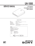
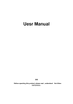
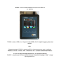
KVE
vector Vector Impedance Antenna analyzer User's Manual
( V20150108 for Kve60C and Kve520A )
1.0 Introduction
Features and Functions:
The KVE anlyzer breaks the size barrier for RF-analyzers by delivering user-friendly
convenience, top-notch accuracy, and a vivid TFT multi-color
display in an ultra-compact package. Although small in size,
1
the Analyzer is loaded with a great selection of SingleFrequency and Swept-Frequency VNA functions.
the Analyzer is for the Amateur check and adjust the antenna at resonance, bandwidth matching.
1. User manual
the Analyzer requires the user to have a certain basic radio theory knowledge and practical experience, or under the guidance of staff to use and
needs to be read before using 。
This manual simply express basic information.
Related information is subject to change and does not make a special notice.
Warninng
Overload Precautions: Never connect your analyzer to a feedline or device carrying a DC-bias voltage. If in doubt,
check the line with a voltmeter. Also, before connecting to outdoor arrays, always short the coax plug momentarily to
discharge any accumulated static buildup. In addition to DC,and static discharge, high RF levels will also damage the
coupler. Never connect to a transceiver that could accidentally transmit into the analyzer, and always check the interference
display when testing in high-RF areas. Disconnect immediately
if high pickup is indicated.
2. Specifications:
1.Screen:
Sharp transflective TFT, 1600 million colors, QVGA resolution. External Hard Mitsubishi scratch-resistant acrylic screen protecter
2.Measuring range:
VSWR: 1: 1.00 - 1: 99.99
Impedance: 0.1 - 999.9 Ohm
Resistance: 0.1 - 999.9 Ohm
Reactance: 0.1 - 999.9 Ohm
3.Frequency range:
60C: 0.5-60MHz
520A:133-177/195-280/395-520MHz
4.Frequency Stability:
60C: <3PPM
520A:<0.5PPM
5.Frequency step:
60C: 100Hz
520A:1000Hz
6.Output Power::
60C: 1dbm (at 14MHz)
520A:3dbm (at 438.500MHz)
7Scan width:
2
60C: 150KHz/300KHz/600KHz/1.2MHz/2.4MHz/6MHz/12MHz/24MHz/48MHz
520A:300KHz/1.5MHz/3MHz/6MHz/12MHz/24MHz/42MHz/75MHz (75MHz仅在395-520MHz段有效)
8Scanning step:
60C: 500Hz/1KHz/2KHz/4KHz/8KHz/20KHz/40KHz/80KHz/160KHz
520A:1KHz/5KHz/10KHz/20KHz/40KHz/80KHz/140KHz/250KHz (250KHz仅在395-520MHz段有效)
9Power Management:3.7-V, 1800-mAh Lithium Polymer battery,Removable
10Charger Source:
Any USB port, analyzer accepts
Micro-USB port(DC output voltage is 5.0-5.5V, and the current output capacity> 500mA )
11Charging indicator:
LED charging-status indicator
12Connector:
BNC
2.1 Quick Start and Review of Analyzer Functions:
3
3. Power, System
1、 Charging the Battery:powered by a 3.7-V 1800-mAH Lithium Polymer battery that comes preinstalled.
To recharge, use a micro-USB-to-standard-USB patch cable (MFJ-5431 or equivalent). The analyzer can be
recharged from any standard computer USB slot capable of delivering 5.0 volts at 500 mA. The analyzer's Micro-USB
charging jack is located on the bottom of the unit. Be sure to charge the battery fully before turning on and operating your
4
analyzer for the first time.
the left of the charging jack (LED not visible unless charging is in progress). Red LED signals normal charging, Green LED
indicates when charging is complete, and Flashing LED warns of a charging fault (battery or power-source problem).
During the charge, a built-in smart-controller monitors battery condition and sets the best charge mode and rate. If the battery
is depleted below 2.9 volts, the charger supplies a 50-ma trickle-charge until the 2.9-volt threshold is restored. It then
increases to a 500-ma constant-current rate until the level reaches 4.2 volts. At that point, the controller switches into the
constant voltage mode and tapers the charge down to shutoff.
If your analyzer is being stored and not in regular use, recharge
it every 2-3 months to maintain battery health. Also, charge
fully before putting it away for extended periods.
Important Charging Note:
Charge the battery before
operating your analyzer for the first time, before storing, and at
2-3 month intervals while in storage.
2、Processor Reset:
operating system is immune to disruption from most glitches and EMP interference.
However, in the unlikely event of a system crash, you can reset
3、Turning Analyzer On and Off:
To apply power, press and hold the power buttom until you hear a
sequence of beeps, then release. This delay of about 3 seconds protects against accidentally turning the analyzer on
while in transit or during routine handling. When the analyzer
turns on, the Boot Screen will appear on the display.
Use the same procedure to turn the analyzer off. Press and
hold the power buttom until you hear the beep
sequence, then release.
3.1 Enter Call Sign or Name:
You may personalize your analyzer by posting call letters or a name (up to eight characters) on the Boot Screen. To program these in, power up
the analyzer and follow the procedure below:
Press the switch labeled System to bring up the system menu.
Press Select to toggle between Auto-Off and Callsign.
Select Callsign.
Press the Encoder Knob to toggle the curser to the start (or left) position. Rotate the Encoder Knob to scroll in your first character
Press the Encoder Knob to move to the second character. Continue building the sequence until your call or name is entered.
Press Exit to return to the MFJ Boot Screen and view your entry.
5
P-3.1
P-3.2
P-3.3
3.2 Switching frequency:
for KVE520A only,Need to select the band。
1. In the boot screen, press the "system" to enter into -System- interface(ID-1)。
2. Using the multi-function button F3 (band selection / BAND), switching between bands.
3.3 Extra notes:
1、In the bottom right of the scanning measurement / SCAN measurement window has antenna field strength indicator.
In stanby mode is display the antenna interference field strength induced. During the test, is presents the measured power output.
When testing, check the S-Antenna bar with the generator turned off to see if disruptive RF levels are being picked up by the antenna.
Single-Frequency Setup:
In Single-Frequency Test Mode, the S-Antenna signal strength indicator is same like the SCAN mode
6
4.0 Operating
4.1 Antenna test Operating 1 (scan mode SCAN):
1、In the start screen, press the SCAN button to scan measurement, automatically enters -Scan Set- (scanning measurement setup) interface (ID1),
ID1
ID2
ID3
a、Press Scan Test bandwidth selection key (SPAN), select the appropriate SACN measurement bandwidth.
b、Rotary encoder potentiometer (by pressing the encoder potentiometer switch at the top of the cycle to select the input bits, input bits at the bottom with a
yellow indicator) entering the center frequency (ID2),
c、Press the SCAN button to scan test, the scan operation.
During the scan test, in order to ensure accurate performance measurements, each frequency will do a very short stay, a scan cycle (300 collection points) about
2-3 seconds.
2、After the measurement, automatic will enter -Present- (Analysis) ID3, will show you three operations:
a, press the "Graph" icon mode button to switch the scan results of the curve display, in addition to
SWR outside the wave curve, Z curve, R curve, X curve.
7
Z wave
R wave
X wave
b、Rotary encoder to move the cursor, see the specific parameters on the measurement results of each scan frequency scanning wave curve on the screen.
c、View scan results data in the process of moving the cursor, you can press "▼ RUN" button, from the current cursor position to re-scan, if you need to change
the
new scan of bandwidth, you can press the "Scan Set" button to enter the measurement setup screen, this time punctuation frequency parameter measurement
screen will automatically bring, after setting the -ScanSet- (scan Settings), press "SCAN" button to scan to. ), You can return -Present- (scan results to see some
revisions are labeled as -Result-) interface operation.
4.2 Measurement data is stored and transferred out:
Before shutdown will automatically save the last scan data . the data will over writeThe analyzer's previous scan data remains in memory, even when the
analyzer is turned off. If you wish to recall it, do the following: From the Boot Screen, press Scan. The analyzer
switches to Scan-Set mode.
From Scan-Set, press Present. The analyzer switchesto Present mode.
1、 Press the "Scan" (scanning measurement) function selection key, enter -Scan Set- (scanning measurement setup) interface,
2、 Press the "Result" (Analysis) interface options to enter into -Result- (Analysis) interface,
3、 Press the "Graph" (scan curve) illustrates the mode selection button, it will automatically bring up the scan data storage.
4.3 Antenna test Operating 2 (single frequency measurement mode Single):
8
In the start screen: Press the "Single" Single frequency measurement mode button, enter -Single- (single frequency measurement mode) screen.
a, rotary encoders, enter the center frequency, specific operations refer to the above "SCAN" scanning measurement mode descriptions.
b, and pause by pressing the test button to test "RUN / Stop", start and stop the test.
Single frequency mode provides a single frequency impedance measurement on the basic parameters of the measured frequency is displayed on the screen.
And with bar and digital form quickly displayed on the screen.
This test can be carried out continuously, unless you are pressing the Stop button.
In this mode, the present apparatus can be used as an accurate signal generator, the signal at the output of the test port.
5.0 Errors and troubleshooting
5.1 Error correction planes:
Calibration Plane Error: The Calibration Plane is the point of reference where all measurements have the greatest
accuracy (Gain Reference = 0dB and Phase Shift = 0 degrees).
For a basic handheld like the MFJ-223, the calibration plane is fixed at the RF connector. Any time a transmission line is
installed, it displaces the load from the calibration plane and introduces error. For SWR readings, the error is mainly caused
by loss in the cable (more loss means greater the error). Generally, this condition isn't a problem because your radio
and the analyzer both see the same reduction in SWR.
However, if you're documenting antenna-SWR for design purposes, the analyzer should be connected directly to the
feedpoint through a short pigtail to minimize error. Calibration-plane error has far more significance for measuring
impedance because of phase rotation in the cable. In fact, impedance readings may swing dramatically, depending on the
cable's electrical length and the severity of the load's mismatch referenced to 50 Ohms. For meaningful impedance data,
always connect the analyzer directly to the DUT using the shortest cable possible.
5.2Reactance Sign Ambiguity:
Most handheld analyzers, including the KVE analyzer, lack the processing capability to directly calculate the reactance sign for complex impedance (Z = Rs
9
±j).
5.3 In Case Of Difficulty:
Note that the KVE analyzer has no user-adjustable alignment controls. Opening the analyzer case to perform unauthorized procedures
could void your warranty. If unit fails to operate properly, please check the suggestions below before contacting dealer for service
or replacement.
Analyzer won't turn on:
Battery may be fully discharged. Plug in to charger, confirm red charge light comes on, and check unit again after a couple hours.
Analyzer functions or display acts erratically:
Reboot the processor . All tests show very high or intermittently high SWR: Check the condition of the analyzer's BNC jack pl us, any
adaptors you may be using to transition to the BNC jack, or condition of antenna connector and coax.
If you are unable to resolve the problem, please follow the specific procedures outlined in the Warranty section for further
assistance.
10