1
)
BAL
(UN
V
dB
–10
V
+48
M
NTO
PHA
L
15
ON
OFF
13
R
NES
PHO
T
OU
16
IN
2TR
14
OR
NIT
MOR IN
2T
6
15/1R IN
2T
10
0
10
0
B
26d
–20
B
26d
–20
–60
–34
B
26d
–60
–34
4
13/1
–16 GAIN
+10
12
–16 GAIN
+10
11
Owner’s10Manual
B
26d
–60
–34
–60
–34
–60
–34
–60
–34
IN
0 GA
–16 GAIN
+10
6
15/1
+10 GAIN
B
26d
NES
PHO
EL
LEV
OR
NIT
MO UT
O
+10 GAIN
EL
LEV
–16 GAIN
+10
R
REO
E
T
LS
E
L
NSO
O
GC
–16 GAIN
+10
AL
IGIT
9
IN
MIX
P
CLI
–3
–6
–9
H
HIG
EQ
D
8
PAN
7
–12
–15
–18
–24
–30
–36
–42
–48
ID
HI-M
MID
LO-
F
PAN
LOW
F
G
G
NEL
HAN
C
ED
ECT
SEL
2
RN
ETU
R
1
12
11
10
9
EL
SEL
5/16
1
4
13/1
SEL
2
URN
T
E
1R
SEL
SEL
REO
E
T
S
TER
S
MA L
SE
S
O
SOL
SEL
SEL
E
O
SOL
O
SOL
ON
ON
FCC INFORMATION (U.S.A.)
1. IMPORTANT NOTICE: DO NOT MODIFY THIS UNIT!
This product, when installed as indicated in the instructions contained in this manual, meets FCC requirements. Modifications not expressly approved by Yamaha
may void your authority, granted by the FCC, to use the product.
2. IMPORTANT: When connecting this product to accessories and/or another product use only high quality shielded cables. Cable/s supplied with this product MUST
be used. Follow all installation instructions. Failure to follow instructions could void your FCC authorization to use this product in the USA.
3. NOTE: This product has been tested and found to comply with the requirements listed in FCC Regulations, Part 15 for Class “B” digital devices. Compliance with
these requirements provides a reasonable level of assurance that your use of this product in a residential environment will not result in harmful interference with
other electronic devices. This equipment generates/uses radio frequencies and, if not installed and used according to the instructions found in the users manual, may
cause interference harmful to the operation of other electronic devices. Compliance with FCC regulations does not guarantee that interference will not occur in all
installations. If this product is found to be the source of interference, which can be determined by turning the unit “OFF” and “ON”, please try to eliminate the
problem by using one of the following measures:
Relocate either this product or the device that is being affected by the interference.
Utilize power outlets that are on different branch (circuit breaker or fuse) circuits or install AC line filter/s.
In the case of radio or TV interference, relocate/reorient the antenna. If the antenna lead-in is 300 ohm ribbon lead, change the lead-in to coaxial type cable.
If these corrective measures do not produce satisfactory results, please contact the local retailer authorized to distribute this type of product. If you can not locate the
appropriate retailer, please contact Yamaha Corporation of America, Electronic Service Division, 6600 Orangethorpe Ave, Buena Park, CA 90620
* This applies only to products distributed by YAMAHA CORPORATION OF AMERICA.
IMPORTANT NOTICE FOR
THE UNITED KINGDOM
Connecting the Plug and Cord
WARNING: THIS APPARATUS MUST BE EARTHED
IMPORTANT: The wires in this mains lead are coloured in accordance with
the following code:
GREEN-AND-YELLOW
BLUE
BROWN
: EARTH
: NEUTRAL
: LIVE
As the colours of the wires in the mains lead of this apparatus may not
correspond with the coloured markings identifying the terminals in your
plug, proceed as follows:
The wire which is coloured GREEN and YELLOW must be connected to
the terminal in the plug which is marked by the letter E or by the safety earth
symbol or coloured GREEN and YELLOW.
The wire which is coloured BLUE must be connected to the terminal which
is marked with the letter N or coloured BLACK.
ADVARSEL!
Lithiumbatteri—Eksplosionsfare ved fejlagtig
håndtering. Udskiftning må kun ske med batteri
af samme fabrikat og type. Levér det brugte
batteri tilbage til leverandoren.
VARNING
Explosionsfara vid felaktigt batteribyte. Använd
samma batterityp eller en ekvivalent typ som
rekommenderas av apparattillverkaren.
Kassera använt batteri enligt fabrikantens
instruktion.
VAROITUS
Paristo voi räjähtää, jos se on virheellisesti
asennettu. Vaihda paristo ainoastaan
laitevalmistajan suosittelemaan tyyppiin. Hävitä
käytetty paristo valmistajan ohjeiden
mukaisesti.
The wire which is coloured BROWN must be connected to the terminal
which is marked with the letter L or coloured RED.
* This applies only to products distributed by YAMAHA KEMBLE
MUSIC (U.K.) LTD.
NEDERLAND
THE NETHERLANDS
● Dit apparaat bevat een lithium batterij voor geheugen
back-up.
● This apparatus contains a lithium battery for memory
back-up.
● Raadpleeg uw leverancier over de verwijdering van de
batterij op het moment dat u het apparaat ann het einde
van de levensduur afdankt of de volgende Yamaha Service
Afdeiing:
Yamaha Music Nederland Service Afdeiing
Kanaalweg 18-G, 3526 KL UTRECHT
Tel. 030-2828425
● For the removal of the battery at the moment of the
disposal at the end of the service life please consult your
retailer or Yamaha Service Center as follows:
Yamaha Music Nederland Service Center
Address: Kanaalweg 18-G, 3526 KL
UTRECHT
Tel: 030-2828425
● Gooi de batterij niet weg, maar lever hem in als KCA.
● Do not throw away the battery. Instead, hand it in as small
chemical waste.
i
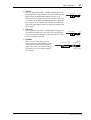
Important Information
Read the Following Before Operating the 01V
Warnings
• Do not locate the 01V in a place subject to excessive heat or in direct sunlight. This
could be a fire hazard.
• Do not place the 01V in a place subject to excessive humidity or dust. This could be
a fire and electrical shock hazard.
• Connect the 01V power cord only to an AC outlet of the type stated in this Owner’s
Manual or as marked on the 01V. Failure to do so is a fire and electrical shock hazard.
• Do not plug several devices into the same AC outlet. This can overload the AC outlet,
and can be a fire and electrical shock hazard. It may also affect the performance of
some devices.
• Do not place heavy objects on the power cord. A damaged power cord is a potential
fire and electrical shock hazard.
• Do not place a container with liquid or small metal objects on top of this unit. Liquid
or metal objects inside this unit are a fire and electrical shock hazard.
• If the power cord is damaged (i.e., cut or a bare wire is exposed), ask your dealer for
a replacement. Using the 01V in this condition is a fire and shock hazard.
• Hold the power cord plug when disconnecting from an AC outlet. Never pull the
cord. Damaging the power cord in this way is a potential fire and electrical shock
hazard.
• Do not place small metal objects on top of the 01V. Metal objects inside the 01V are
a fire and electrical shock hazard.
• Do not block the 01V ventilation slots. The 01V has ventilation slots on the top and
rear to prevent the internal temperature from rising. Blocked ventilation slots are a
fire hazard.
• Do not try to modify the 01V. This could be a fire and electrical shock hazard.
• The 01V operating temperature is between 5˚C and 35˚C (41˚F and 95˚F).
• If lightning begins to occur, turn off the power switch of the unit as soon as possible,
and unplug the power cable plug from the electrical outlet.
• If there is a possibility of lightning, do not touch the power cable plug if it is still connected. Doing so may be an electrical shock hazard.
• If you notice any abnormality—such as smoke, odor, or noise—turn off the 01V
immediately. Remove the power cord from the AC outlet. Confirm that the abnormality is no longer present. Consult your dealer for repair. Using the 01V in this condition is a fire and shock hazard.
Cautions
• Turn off all audio devices and speakers when connecting to the 01V. Refer to the
owner’s manual for each device. Use the correct cables and connect as specified.
• If a foreign object or water gets inside the 01V, turn it off immediately. Remove the
power cord from the AC outlet. Consult your dealer for repair. Using the 01V in this
condition is a fire and electrical shock hazard.
01V—Owner’s Manual
ii
• If you plan not to use the 01V for a long period of time, remove the power cord from
the AC outlet. Leaving the 01V connected is a fire hazard.
• Do not use benzene, thinner, cleaning detergent, or a chemical cloth to clean the 01V.
Use only a soft, dry cloth.
• The 01V is a heavy piece of equipment. Always grip the underneath, not the side panels, when lifting.
Interference
01V uses high-frequency digital circuits that may cause interference on radios and televisions placed close to it. If interference does occur, relocate the affected equipment.
Copyright
© 1998 Yamaha Corporation. All rights reserved.
No part of the 01V software or this Owner’s Manual may be reproduced or distributed
in any form or by any means without the prior written authorization of Yamaha Corporation.
Trademarks
ADAT MultiChannel Optical Digital Interface is a trademark and ADAT and Alesis are
registered trademarks of Alesis Corporation. Macintosh is a registered trademark of
Apple Computer, Inc. Pro Tools is a registered trademark of Digidesign or Avid Technology, Inc. Tascam Digital Interface is a trademark and Tascam and TEAC are registered trademarks of TEAC Corporation. Windows is a trademark of Microsoft
Corporation.
All other trademarks are the property of their respective holders and are hereby
acknowledged.
Package Contents
The 01V package should contain the following items. Make sure that you have them all.
• 01V Digital Mixing Console
• Owner’s Manual
Contact your Yamaha dealer if anything is missing.
Keep this manual for future reference!
01V—Owner’s Manual
iii
Contents
Contents
1
Welcome to the 01V . . . . . . . . . . . . . . . . . . . . . . . . 1
Welcome to the 01V . . . . . . . . . . . . . . . . . . . . . . . . . . . . . . . . . . . . . . . . .
About this Owner’s Manual . . . . . . . . . . . . . . . . . . . . . . . . . . . . . . . . . . .
01V Installation . . . . . . . . . . . . . . . . . . . . . . . . . . . . . . . . . . . . . . . . . . . . .
01V Features . . . . . . . . . . . . . . . . . . . . . . . . . . . . . . . . . . . . . . . . . . . . . . . .
Key Feature Discussion . . . . . . . . . . . . . . . . . . . . . . . . . . . . . . . . . . . . . . .
2
Getting Started . . . . . . . . . . . . . . . . . . . . . . . . . . . . 9
01V System Example . . . . . . . . . . . . . . . . . . . . . . . . . . . . . . . . . . . . . . . .
Important Wordclock Information . . . . . . . . . . . . . . . . . . . . . . . . . . . .
Connecting the Power Cord . . . . . . . . . . . . . . . . . . . . . . . . . . . . . . . . . .
Turning On the 01V . . . . . . . . . . . . . . . . . . . . . . . . . . . . . . . . . . . . . . . .
Turning Off the 01V . . . . . . . . . . . . . . . . . . . . . . . . . . . . . . . . . . . . . . . .
3
2
2
2
3
4
10
11
11
11
11
Touring the 01V . . . . . . . . . . . . . . . . . . . . . . . . . . . 13
Top Panel Controls . . . . . . . . . . . . . . . . . . . . . . . . . . . . . . . . . . . . . . . . . 14
Inputs & Outputs . . . . . . . . . . . . . . . . . . . . . . . . . . . . . . . . . . . . . . . . . . . 20
Block Diagram . . . . . . . . . . . . . . . . . . . . . . . . . . . . . . . . . . . . . . . . . . . . . 24
4
Getting Around the User Interface . . . . . . . . . . . . 27
About the User Interface . . . . . . . . . . . . . . . . . . . . . . . . . . . . . . . . . . . . .
Display . . . . . . . . . . . . . . . . . . . . . . . . . . . . . . . . . . . . . . . . . . . . . . . . . . .
Display Elements . . . . . . . . . . . . . . . . . . . . . . . . . . . . . . . . . . . . . . . . . . .
Cursor Buttons . . . . . . . . . . . . . . . . . . . . . . . . . . . . . . . . . . . . . . . . . . . . .
PARAMETER Wheel . . . . . . . . . . . . . . . . . . . . . . . . . . . . . . . . . . . . . . . .
–1/DEC & +1/INC Buttons . . . . . . . . . . . . . . . . . . . . . . . . . . . . . . . . . . .
ENTER Button . . . . . . . . . . . . . . . . . . . . . . . . . . . . . . . . . . . . . . . . . . . . .
Fader Modes . . . . . . . . . . . . . . . . . . . . . . . . . . . . . . . . . . . . . . . . . . . . . . .
Title Edit Dialog Box . . . . . . . . . . . . . . . . . . . . . . . . . . . . . . . . . . . . . . . .
5
28
28
30
31
31
31
31
32
37
Input Channels . . . . . . . . . . . . . . . . . . . . . . . . . . . 39
Input Channel Overview . . . . . . . . . . . . . . . . . . . . . . . . . . . . . . . . . . . . .
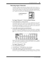
Phantom Powering . . . . . . . . . . . . . . . . . . . . . . . . . . . . . . . . . . . . . . . . .
Pad Switches . . . . . . . . . . . . . . . . . . . . . . . . . . . . . . . . . . . . . . . . . . . . . . .
Setting Input Channel Gain . . . . . . . . . . . . . . . . . . . . . . . . . . . . . . . . . .
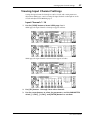
Metering Input Channels . . . . . . . . . . . . . . . . . . . . . . . . . . . . . . . . . . . .
Changing the Input Phase . . . . . . . . . . . . . . . . . . . . . . . . . . . . . . . . . . . .
Attenuating Input Channel Signals . . . . . . . . . . . . . . . . . . . . . . . . . . . .
Applying EQ to Input Channels . . . . . . . . . . . . . . . . . . . . . . . . . . . . . . .
Input Channels Dynamics Processors . . . . . . . . . . . . . . . . . . . . . . . . . .
Delaying Channel Signals . . . . . . . . . . . . . . . . . . . . . . . . . . . . . . . . . . . .
Muting Input Channels . . . . . . . . . . . . . . . . . . . . . . . . . . . . . . . . . . . . . .
Setting Input Channel Levels . . . . . . . . . . . . . . . . . . . . . . . . . . . . . . . . .
Panning Input Channels . . . . . . . . . . . . . . . . . . . . . . . . . . . . . . . . . . . . .
Routing Input Channels . . . . . . . . . . . . . . . . . . . . . . . . . . . . . . . . . . . . .
Monitoring Input Channels . . . . . . . . . . . . . . . . . . . . . . . . . . . . . . . . . .
Input Channels & Aux Sends . . . . . . . . . . . . . . . . . . . . . . . . . . . . . . . . .
40
41
41
41
41
42
43
44
44
45
46
46
47
49
50
50
01V—Owner’s Manual
iv
Contents
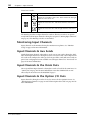
Input Channels & the Omni Outs . . . . . . . . . . . . . . . . . . . . . . . . . . . . .
Input Channels & the Option I/O Outs . . . . . . . . . . . . . . . . . . . . . . . . .
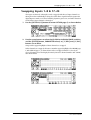
Swapping Inputs 1–8 & 17–24 . . . . . . . . . . . . . . . . . . . . . . . . . . . . . . . .
Pairing Input Channels . . . . . . . . . . . . . . . . . . . . . . . . . . . . . . . . . . . . . .
Grouping Faders . . . . . . . . . . . . . . . . . . . . . . . . . . . . . . . . . . . . . . . . . . .
Grouping Mutes . . . . . . . . . . . . . . . . . . . . . . . . . . . . . . . . . . . . . . . . . . . .
Viewing Input Channel Settings . . . . . . . . . . . . . . . . . . . . . . . . . . . . . . .
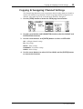
Copying & Swapping Channel Settings . . . . . . . . . . . . . . . . . . . . . . . . .
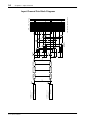
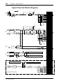
Input Channel Block Diagram . . . . . . . . . . . . . . . . . . . . . . . . . . . . . . . .
6
EQ . . . . . . . . . . . . . . . . . . . . . . . . . . . . . . . . . . . . . . 61
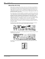
About the 01V EQ . . . . . . . . . . . . . . . . . . . . . . . . . . . . . . . . . . . . . . . . . .
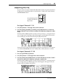
Adjusting the EQ . . . . . . . . . . . . . . . . . . . . . . . . . . . . . . . . . . . . . . . . . . .
EQ Specs . . . . . . . . . . . . . . . . . . . . . . . . . . . . . . . . . . . . . . . . . . . . . . . . . .
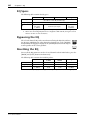
Bypassing the EQ . . . . . . . . . . . . . . . . . . . . . . . . . . . . . . . . . . . . . . . . . . .
Resetting the EQ . . . . . . . . . . . . . . . . . . . . . . . . . . . . . . . . . . . . . . . . . . . .
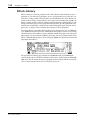
EQ Library . . . . . . . . . . . . . . . . . . . . . . . . . . . . . . . . . . . . . . . . . . . . . . . .
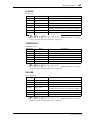
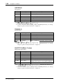
Preset EQ Program List . . . . . . . . . . . . . . . . . . . . . . . . . . . . . . . . . . . . . .
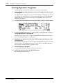
Storing EQ Programs . . . . . . . . . . . . . . . . . . . . . . . . . . . . . . . . . . . . . . . .
Recalling EQ Programs . . . . . . . . . . . . . . . . . . . . . . . . . . . . . . . . . . . . . .
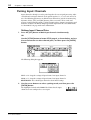
Editing EQ Program Titles . . . . . . . . . . . . . . . . . . . . . . . . . . . . . . . . . . .
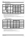
Preset EQ Program Parameters . . . . . . . . . . . . . . . . . . . . . . . . . . . . . . .
7
76
77
77
77
78
78
79
80
81
82
83
84
84
85
85
86
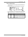
Stereo Output . . . . . . . . . . . . . . . . . . . . . . . . . . . . . 87
About the Stereo Output . . . . . . . . . . . . . . . . . . . . . . . . . . . . . . . . . . . . .
Analog Stereo Output . . . . . . . . . . . . . . . . . . . . . . . . . . . . . . . . . . . . . . .
2TR Out & the Stereo Output . . . . . . . . . . . . . . . . . . . . . . . . . . . . . . . . .
Coaxial Digital Out & the Stereo Output . . . . . . . . . . . . . . . . . . . . . . .
Option I/O & the Stereo Output . . . . . . . . . . . . . . . . . . . . . . . . . . . . . .
Omni Outs & the Stereo Output . . . . . . . . . . . . . . . . . . . . . . . . . . . . . .
Solo & the Stereo Output . . . . . . . . . . . . . . . . . . . . . . . . . . . . . . . . . . . .
Monitoring the Stereo Output . . . . . . . . . . . . . . . . . . . . . . . . . . . . . . . .
01V—Owner’s Manual
62
63
66
66
66
67
67
68
69
70
71
Solo, Monitors & Meters . . . . . . . . . . . . . . . . . . . . 75
About Monitor & Solo . . . . . . . . . . . . . . . . . . . . . . . . . . . . . . . . . . . . . . .
Monitor Outputs . . . . . . . . . . . . . . . . . . . . . . . . . . . . . . . . . . . . . . . . . . .
Phones . . . . . . . . . . . . . . . . . . . . . . . . . . . . . . . . . . . . . . . . . . . . . . . . . . . .
Two-track Input (2TR IN) . . . . . . . . . . . . . . . . . . . . . . . . . . . . . . . . . . .
Monitor Setup . . . . . . . . . . . . . . . . . . . . . . . . . . . . . . . . . . . . . . . . . . . . .
Using Monitor . . . . . . . . . . . . . . . . . . . . . . . . . . . . . . . . . . . . . . . . . . . . .
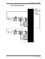
Monitor Block Diagram . . . . . . . . . . . . . . . . . . . . . . . . . . . . . . . . . . . . .
Solo Setup . . . . . . . . . . . . . . . . . . . . . . . . . . . . . . . . . . . . . . . . . . . . . . . . .
Using Solo . . . . . . . . . . . . . . . . . . . . . . . . . . . . . . . . . . . . . . . . . . . . . . . . .
Solo Block Diagram . . . . . . . . . . . . . . . . . . . . . . . . . . . . . . . . . . . . . . . . .
Metering Signal Levels . . . . . . . . . . . . . . . . . . . . . . . . . . . . . . . . . . . . . . .
Main Stereo Meters . . . . . . . . . . . . . . . . . . . . . . . . . . . . . . . . . . . . . . . . .
Peak Hold . . . . . . . . . . . . . . . . . . . . . . . . . . . . . . . . . . . . . . . . . . . . . . . . .
Setting the Metering Point . . . . . . . . . . . . . . . . . . . . . . . . . . . . . . . . . . .
Option I/O Meters (input channels 17–24) . . . . . . . . . . . . . . . . . . . . . .
Effects Send Meters . . . . . . . . . . . . . . . . . . . . . . . . . . . . . . . . . . . . . . . . .
8
50
50
51
52
55
56
57
59
60
88
88
88
88
88
88
88
88
v
Contents
Metering the Stereo Output . . . . . . . . . . . . . . . . . . . . . . . . . . . . . . . . . .
Routing Signals to the Stereo Output . . . . . . . . . . . . . . . . . . . . . . . . . .
Viewing Stereo Output Settings . . . . . . . . . . . . . . . . . . . . . . . . . . . . . . .
Setting the Stereo Output Level . . . . . . . . . . . . . . . . . . . . . . . . . . . . . . .
Muting the Stereo Output . . . . . . . . . . . . . . . . . . . . . . . . . . . . . . . . . . . .
Balancing the Stereo Output . . . . . . . . . . . . . . . . . . . . . . . . . . . . . . . . . .
Applying EQ to the Stereo Output . . . . . . . . . . . . . . . . . . . . . . . . . . . . .
Stereo Output Dynamics Processors . . . . . . . . . . . . . . . . . . . . . . . . . . .
Stereo Output Delay . . . . . . . . . . . . . . . . . . . . . . . . . . . . . . . . . . . . . . . .
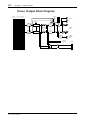
Stereo Output Block Diagram . . . . . . . . . . . . . . . . . . . . . . . . . . . . . . . .
9
89
89
89
90
90
90
90
90
91
92
Aux Sends . . . . . . . . . . . . . . . . . . . . . . . . . . . . . . . 93
About the Aux Sends . . . . . . . . . . . . . . . . . . . . . . . . . . . . . . . . . . . . . . . .
Option I/O & the Aux Sends . . . . . . . . . . . . . . . . . . . . . . . . . . . . . . . . . .
Omni Outs & the Aux Sends . . . . . . . . . . . . . . . . . . . . . . . . . . . . . . . . . .
Monitoring Aux Sends . . . . . . . . . . . . . . . . . . . . . . . . . . . . . . . . . . . . . .
Metering Aux Sends . . . . . . . . . . . . . . . . . . . . . . . . . . . . . . . . . . . . . . . . .
Sending Channel Signals to Aux Sends . . . . . . . . . . . . . . . . . . . . . . . . .
Pre-fader/Post-fader Aux Sends . . . . . . . . . . . . . . . . . . . . . . . . . . . . . . .
Viewing Aux Send Settings . . . . . . . . . . . . . . . . . . . . . . . . . . . . . . . . . . .
Setting Aux Send Master Levels . . . . . . . . . . . . . . . . . . . . . . . . . . . . . . .
Muting Aux Sends . . . . . . . . . . . . . . . . . . . . . . . . . . . . . . . . . . . . . . . . . .
Applying EQ to Aux Sends . . . . . . . . . . . . . . . . . . . . . . . . . . . . . . . . . . .
Aux Send Dynamics Processors . . . . . . . . . . . . . . . . . . . . . . . . . . . . . . .
Pairing Aux Sends . . . . . . . . . . . . . . . . . . . . . . . . . . . . . . . . . . . . . . . . . .
Aux Send Block Diagram . . . . . . . . . . . . . . . . . . . . . . . . . . . . . . . . . . . .
Stereo Pair Aux Send Block Diagram . . . . . . . . . . . . . . . . . . . . . . . . . . .
94
94
94
94
94
95
97
98
99
100
100
100
101
104
105
10 Bus Outs . . . . . . . . . . . . . . . . . . . . . . . . . . . . . . . . . 107
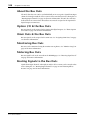
About the Bus Outs . . . . . . . . . . . . . . . . . . . . . . . . . . . . . . . . . . . . . . . . .
Option I/O & the Bus Outs . . . . . . . . . . . . . . . . . . . . . . . . . . . . . . . . . . .
Omni Outs & the Bus Outs . . . . . . . . . . . . . . . . . . . . . . . . . . . . . . . . . . .
Monitoring Bus Outs . . . . . . . . . . . . . . . . . . . . . . . . . . . . . . . . . . . . . . . .
Metering Bus Outs . . . . . . . . . . . . . . . . . . . . . . . . . . . . . . . . . . . . . . . . . .
Routing Signals to the Bus Outs . . . . . . . . . . . . . . . . . . . . . . . . . . . . . . .
Setting Bus Out Master Levels . . . . . . . . . . . . . . . . . . . . . . . . . . . . . . . .
Muting Bus Outs . . . . . . . . . . . . . . . . . . . . . . . . . . . . . . . . . . . . . . . . . . .
Routing Bus Signals to the Stereo Bus . . . . . . . . . . . . . . . . . . . . . . . . . .
Pairing Bus Outs . . . . . . . . . . . . . . . . . . . . . . . . . . . . . . . . . . . . . . . . . . .
Bus Out Block Diagram . . . . . . . . . . . . . . . . . . . . . . . . . . . . . . . . . . . . . .
Stereo Pair Bus Out Block Diagram . . . . . . . . . . . . . . . . . . . . . . . . . . . .
108
108
108
108
108
108
109
109
110
111
112
113
11 Omni Outs . . . . . . . . . . . . . . . . . . . . . . . . . . . . . . . 115
About the Omni Outs . . . . . . . . . . . . . . . . . . . . . . . . . . . . . . . . . . . . . . .
Omni Outs . . . . . . . . . . . . . . . . . . . . . . . . . . . . . . . . . . . . . . . . . . . . . . . .
Assigning Omni Outs . . . . . . . . . . . . . . . . . . . . . . . . . . . . . . . . . . . . . . .
Omni Out Delay . . . . . . . . . . . . . . . . . . . . . . . . . . . . . . . . . . . . . . . . . . . .
Omni Out Block Diagram . . . . . . . . . . . . . . . . . . . . . . . . . . . . . . . . . . . .
116
116
116
117
118
01V—Owner’s Manual
vi
Contents
12 Effects . . . . . . . . . . . . . . . . . . . . . . . . . . . . . . . . . . 119
About the Onboard Effects . . . . . . . . . . . . . . . . . . . . . . . . . . . . . . . . . . .
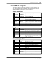
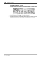
Preset Effects Programs . . . . . . . . . . . . . . . . . . . . . . . . . . . . . . . . . . . . . .
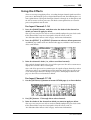
Using the Effects . . . . . . . . . . . . . . . . . . . . . . . . . . . . . . . . . . . . . . . . . . . .
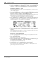
Pre-fader/Post-fader Effects Sends . . . . . . . . . . . . . . . . . . . . . . . . . . . . .
Viewing Effects Send Settings . . . . . . . . . . . . . . . . . . . . . . . . . . . . . . . . .
Metering Effects Sends . . . . . . . . . . . . . . . . . . . . . . . . . . . . . . . . . . . . . . .
Setting Effects Send Master Levels . . . . . . . . . . . . . . . . . . . . . . . . . . . . .
Muting Effects Sends . . . . . . . . . . . . . . . . . . . . . . . . . . . . . . . . . . . . . . . .
Viewing Effects Returns Settings . . . . . . . . . . . . . . . . . . . . . . . . . . . . . .
Metering Effects Returns . . . . . . . . . . . . . . . . . . . . . . . . . . . . . . . . . . . . .
Applying EQ to Effects Returns . . . . . . . . . . . . . . . . . . . . . . . . . . . . . . .
Muting Effects Returns . . . . . . . . . . . . . . . . . . . . . . . . . . . . . . . . . . . . . .
Setting Effects Returns Levels . . . . . . . . . . . . . . . . . . . . . . . . . . . . . . . . .
Panning Effects Returns . . . . . . . . . . . . . . . . . . . . . . . . . . . . . . . . . . . . .
Routing Effects Returns . . . . . . . . . . . . . . . . . . . . . . . . . . . . . . . . . . . . . .
Monitoring Effects Returns . . . . . . . . . . . . . . . . . . . . . . . . . . . . . . . . . . .
Effects Returns & Aux Sends . . . . . . . . . . . . . . . . . . . . . . . . . . . . . . . . . .
Effects Library . . . . . . . . . . . . . . . . . . . . . . . . . . . . . . . . . . . . . . . . . . . . . .
Storing Effects Programs . . . . . . . . . . . . . . . . . . . . . . . . . . . . . . . . . . . . .
Recalling Effects Programs . . . . . . . . . . . . . . . . . . . . . . . . . . . . . . . . . . .
Editing Effects Program Titles . . . . . . . . . . . . . . . . . . . . . . . . . . . . . . . .
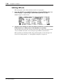
Editing Effects . . . . . . . . . . . . . . . . . . . . . . . . . . . . . . . . . . . . . . . . . . . . . .
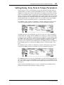
Setting Delay, Freq, Note & Tempo Parameters . . . . . . . . . . . . . . . . . .
Effects Parameters . . . . . . . . . . . . . . . . . . . . . . . . . . . . . . . . . . . . . . . . . .
Effects Block Diagram . . . . . . . . . . . . . . . . . . . . . . . . . . . . . . . . . . . . . . .
120
121
123
125
127
127
128
129
130
130
130
130
131
131
131
131
131
132
133
134
135
136
137
138
159
13 Dynamics Processors . . . . . . . . . . . . . . . . . . . . . . 161
About the Dynamics Processors . . . . . . . . . . . . . . . . . . . . . . . . . . . . . . .
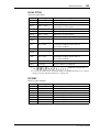
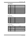
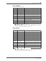
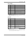
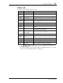
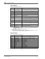
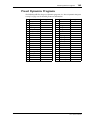
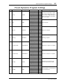
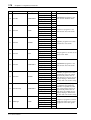
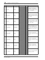
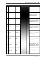
Preset Dynamics Programs . . . . . . . . . . . . . . . . . . . . . . . . . . . . . . . . . . .
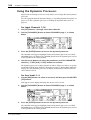
Using the Dynamics Processors . . . . . . . . . . . . . . . . . . . . . . . . . . . . . . .
Editing the Dynamics Processors . . . . . . . . . . . . . . . . . . . . . . . . . . . . . .
Processor Types . . . . . . . . . . . . . . . . . . . . . . . . . . . . . . . . . . . . . . . . . . . .
Dynamics Library . . . . . . . . . . . . . . . . . . . . . . . . . . . . . . . . . . . . . . . . . . .
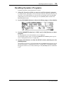
Storing Dynamics Programs . . . . . . . . . . . . . . . . . . . . . . . . . . . . . . . . . .
Recalling Dynamics Programs . . . . . . . . . . . . . . . . . . . . . . . . . . . . . . . .
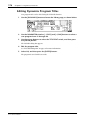
Editing Dynamics Program Titles . . . . . . . . . . . . . . . . . . . . . . . . . . . . .
Preset Dynamics Program Settings . . . . . . . . . . . . . . . . . . . . . . . . . . . . .
162
163
164
166
167
173
174
175
176
177
14 Scene Memories . . . . . . . . . . . . . . . . . . . . . . . . . . 183
About Scene Memories . . . . . . . . . . . . . . . . . . . . . . . . . . . . . . . . . . . . . .
What’s Stored in Scene Memories? . . . . . . . . . . . . . . . . . . . . . . . . . . . .
About the Edit Buffer & Indicator . . . . . . . . . . . . . . . . . . . . . . . . . . . . .
Scene Memory 00 . . . . . . . . . . . . . . . . . . . . . . . . . . . . . . . . . . . . . . . . . . .
Scene Memory Display Area . . . . . . . . . . . . . . . . . . . . . . . . . . . . . . . . . .
Storing Mix Scenes . . . . . . . . . . . . . . . . . . . . . . . . . . . . . . . . . . . . . . . . . .
Recalling Mix Scenes . . . . . . . . . . . . . . . . . . . . . . . . . . . . . . . . . . . . . . . .
Recalling Mix Scenes Using MIDI Program Change Messages . . . . . .
Undoing Mix Scene Recalls . . . . . . . . . . . . . . . . . . . . . . . . . . . . . . . . . . .
Protecting Scene Memories . . . . . . . . . . . . . . . . . . . . . . . . . . . . . . . . . . .
01V—Owner’s Manual
184
184
185
185
185
186
187
188
189
189
vii
Contents
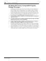
Editing Scene Memory Titles . . . . . . . . . . . . . . . . . . . . . . . . . . . . . . . . .
Renumbering Scene Memories . . . . . . . . . . . . . . . . . . . . . . . . . . . . . . . .
Setting a Fade Time . . . . . . . . . . . . . . . . . . . . . . . . . . . . . . . . . . . . . . . . .
Recalling Scene Data Safely . . . . . . . . . . . . . . . . . . . . . . . . . . . . . . . . . . .
190
190
191
192
15 Other Functions . . . . . . . . . . . . . . . . . . . . . . . . . . . 193
Assigning Faders & On Buttons . . . . . . . . . . . . . . . . . . . . . . . . . . . . . . .
Using the Oscillator . . . . . . . . . . . . . . . . . . . . . . . . . . . . . . . . . . . . . . . . .
Setting 01V Preferences . . . . . . . . . . . . . . . . . . . . . . . . . . . . . . . . . . . . . .
Initializing the 01V . . . . . . . . . . . . . . . . . . . . . . . . . . . . . . . . . . . . . . . . .
Calibrating the Faders . . . . . . . . . . . . . . . . . . . . . . . . . . . . . . . . . . . . . . .
194
202
203
204
204
16 Using the Digital Inputs & Outputs . . . . . . . . . . . 205
About Wordclocks . . . . . . . . . . . . . . . . . . . . . . . . . . . . . . . . . . . . . . . . . .
Setting the Wordclock . . . . . . . . . . . . . . . . . . . . . . . . . . . . . . . . . . . . . . .
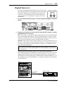
Digital Stereo Out . . . . . . . . . . . . . . . . . . . . . . . . . . . . . . . . . . . . . . . . . .
Output Dither . . . . . . . . . . . . . . . . . . . . . . . . . . . . . . . . . . . . . . . . . . . . .
Digital Stereo In . . . . . . . . . . . . . . . . . . . . . . . . . . . . . . . . . . . . . . . . . . . .
Cascading 01Vs . . . . . . . . . . . . . . . . . . . . . . . . . . . . . . . . . . . . . . . . . . . .
About Option I/O Cards . . . . . . . . . . . . . . . . . . . . . . . . . . . . . . . . . . . . .
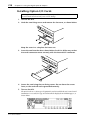
Installing Option I/O Cards . . . . . . . . . . . . . . . . . . . . . . . . . . . . . . . . . .
Assigning Option I/O Digital Outputs . . . . . . . . . . . . . . . . . . . . . . . . . .
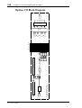
Option I/O Block Diagram . . . . . . . . . . . . . . . . . . . . . . . . . . . . . . . . . . .
206
209
211
212
213
214
216
218
219
220
17 MIDI . . . . . . . . . . . . . . . . . . . . . . . . . . . . . . . . . . . . 221
MIDI & the 01V . . . . . . . . . . . . . . . . . . . . . . . . . . . . . . . . . . . . . . . . . . . .
MIDI Ports . . . . . . . . . . . . . . . . . . . . . . . . . . . . . . . . . . . . . . . . . . . . . . . .
MIDI Receive Indicators . . . . . . . . . . . . . . . . . . . . . . . . . . . . . . . . . . . . .
MIDI Setup . . . . . . . . . . . . . . . . . . . . . . . . . . . . . . . . . . . . . . . . . . . . . . . .
Program Change Scene Recall . . . . . . . . . . . . . . . . . . . . . . . . . . . . . . . .
Control Change Parameter Control . . . . . . . . . . . . . . . . . . . . . . . . . . . .
System Exclusive Parameter Control . . . . . . . . . . . . . . . . . . . . . . . . . . .
Bulk Dump . . . . . . . . . . . . . . . . . . . . . . . . . . . . . . . . . . . . . . . . . . . . . . . .
Local Control . . . . . . . . . . . . . . . . . . . . . . . . . . . . . . . . . . . . . . . . . . . . . .
MIDI Machine Control . . . . . . . . . . . . . . . . . . . . . . . . . . . . . . . . . . . . . .
User Defined MIDI Controllers . . . . . . . . . . . . . . . . . . . . . . . . . . . . . . .
Linking 01Vs . . . . . . . . . . . . . . . . . . . . . . . . . . . . . . . . . . . . . . . . . . . . . . .
222
222
224
224
227
229
231
232
234
236
238
239
18 System Examples . . . . . . . . . . . . . . . . . . . . . . . . . . 241
01V & ADAT-Interface Recorder . . . . . . . . . . . . . . . . . . . . . . . . . . . . . .
Two 01Vs & two ADAT-Interface Recorders . . . . . . . . . . . . . . . . . . . .
01V & Tascam-Interface Recorder . . . . . . . . . . . . . . . . . . . . . . . . . . . . .
Two 01Vs & two Tascam-Interface Recorders . . . . . . . . . . . . . . . . . . .
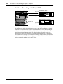
01V & Pro Tools (AES/EBU) . . . . . . . . . . . . . . . . . . . . . . . . . . . . . . . . .
242
244
246
248
250
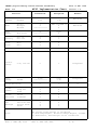
Troubleshooting . . . . . . . . . . . . . . . . . . . . . . . . . . . . . 253
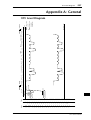
Appendix A: General . . . . . . . . . . . . . . . . . . . . . . . . . . 257
01V Level Diagram . . . . . . . . . . . . . . . . . . . . . . . . . . . . . . . . . . . . . . . . . . 257
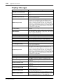
Display Messages . . . . . . . . . . . . . . . . . . . . . . . . . . . . . . . . . . . . . . . . . . . 258
01V—Owner’s Manual
viii
Contents
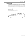
Security Cover . . . . . . . . . . . . . . . . . . . . . . . . . . . . . . . . . . . . . . . . . . . . . 259
Rack-mounting Kit . . . . . . . . . . . . . . . . . . . . . . . . . . . . . . . . . . . . . . . . . 259
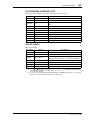
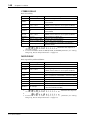
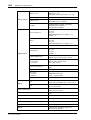
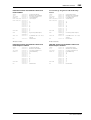
Appendix B: Specifications . . . . . . . . . . . . . . . . . . . . . 261
General . . . . . . . . . . . . . . . . . . . . . . . . . . . . . . . . . . . . . . . . . . . . . . . . . . . 261
Input Channels 1–16 . . . . . . . . . . . . . . . . . . . . . . . . . . . . . . . . . . . . . . . . 263
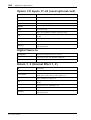
Option I/O Inputs 17–24 (need optional card) . . . . . . . . . . . . . . . . . . . 264
Digital Stereo In . . . . . . . . . . . . . . . . . . . . . . . . . . . . . . . . . . . . . . . . . . . . 264
Return 1, 2 (Internal Effect 1, 2) . . . . . . . . . . . . . . . . . . . . . . . . . . . . . . . 264
Bus 1–4 . . . . . . . . . . . . . . . . . . . . . . . . . . . . . . . . . . . . . . . . . . . . . . . . . . . 265
Aux 1–4 . . . . . . . . . . . . . . . . . . . . . . . . . . . . . . . . . . . . . . . . . . . . . . . . . . . 265
Stereo Out . . . . . . . . . . . . . . . . . . . . . . . . . . . . . . . . . . . . . . . . . . . . . . . . . 265
Omni Out 1–4 . . . . . . . . . . . . . . . . . . . . . . . . . . . . . . . . . . . . . . . . . . . . . 265
Monitor Out (Solo) . . . . . . . . . . . . . . . . . . . . . . . . . . . . . . . . . . . . . . . . . 266
Digital Stereo Out . . . . . . . . . . . . . . . . . . . . . . . . . . . . . . . . . . . . . . . . . . 266
Option I/O Output (need optional card) . . . . . . . . . . . . . . . . . . . . . . . 266
Memories & Libraries . . . . . . . . . . . . . . . . . . . . . . . . . . . . . . . . . . . . . . . 266
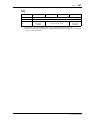
EQ . . . . . . . . . . . . . . . . . . . . . . . . . . . . . . . . . . . . . . . . . . . . . . . . . . . . . . . 267
Analog Inputs . . . . . . . . . . . . . . . . . . . . . . . . . . . . . . . . . . . . . . . . . . . . . . 268
Analog Outputs . . . . . . . . . . . . . . . . . . . . . . . . . . . . . . . . . . . . . . . . . . . . 268
Digital Audio Inputs . . . . . . . . . . . . . . . . . . . . . . . . . . . . . . . . . . . . . . . . 269
Digital Audio Outputs . . . . . . . . . . . . . . . . . . . . . . . . . . . . . . . . . . . . . . . 269
Option I/O Cards . . . . . . . . . . . . . . . . . . . . . . . . . . . . . . . . . . . . . . . . . . . 269
Control I/O . . . . . . . . . . . . . . . . . . . . . . . . . . . . . . . . . . . . . . . . . . . . . . . . 270
01V Dimensions . . . . . . . . . . . . . . . . . . . . . . . . . . . . . . . . . . . . . . . . . . . . 271
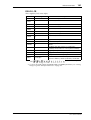
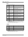
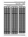
Appendix C: MIDI . . . . . . . . . . . . . . . . . . . . . . . . . . . . 273
Scene Memory to Program Change Table . . . . . . . . . . . . . . . . . . . . . . .
01V Parameter to Control Change Table . . . . . . . . . . . . . . . . . . . . . .
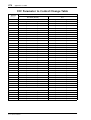
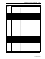
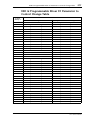
03D & Programmable Mixer 01 Parameter to Control Change Table
MIDI Data Format . . . . . . . . . . . . . . . . . . . . . . . . . . . . . . . . . . . . . . . . . .
273
274
277
280
Appendix D: Resources . . . . . . . . . . . . . . . . . . . . . . . 291
Books . . . . . . . . . . . . . . . . . . . . . . . . . . . . . . . . . . . . . . . . . . . . . . . . . . . . . 291
Yamaha Web Site . . . . . . . . . . . . . . . . . . . . . . . . . . . . . . . . . . . . . . . . . . . 291
Glossary . . . . . . . . . . . . . . . . . . . . . . . . . . . . . . . . . . . 293
Index . . . . . . . . . . . . . . . . . . . . . . . . . . . . . . . . . . . . . . 297
01V—Owner’s Manual
Welcome to the 01V
1
Welcome to the 01V
1
In this chapter...
Welcome to the 01V . . . . . . . . . . . . . . . . . . . . . . . . . . . . . . . . . . . . . . . . . . . . . . . .
About this Owner’s Manual . . . . . . . . . . . . . . . . . . . . . . . . . . . . . . . . . . . . . . . . . .
01V Installation . . . . . . . . . . . . . . . . . . . . . . . . . . . . . . . . . . . . . . . . . . . . . . . . . . . .
01V Features . . . . . . . . . . . . . . . . . . . . . . . . . . . . . . . . . . . . . . . . . . . . . . . . . . . . . .
Key Feature Discussion . . . . . . . . . . . . . . . . . . . . . . . . . . . . . . . . . . . . . . . . . . . . .
2
2
2
3
4
01V—Owner’s Manual
2
Chapter 1—Welcome to the 01V
Welcome to the 01V
Thank you for choosing the Yamaha 01V Digital Mixing Console. Based on the highly
successful Yamaha digital mixer series, the Yamaha 01V has been designed with MIDI
musicians and small sound reinforcement applications in mind, although its versatility,
compactness, and ease-of-use will appeal to both professional and semiprofessional
users.
About this Owner’s Manual
This Owner’s Manual contains all the information you’ll need in order to operate your
01V Digital Mixing Console. Use the table of contents to find general information and
familiarize yourself with the organization of this manual, and use the index to locate
specific items. A glossary of 01V-related jargon is provided on page 293.
Each chapter covers a specific section of the 01V. The Input Channels Chapter, for
example, explains all about input channels, while the Scene Memories Chapter deals
with scene memories. The content of each chapter should be fairly obvious from its
title. Items such as EQ and dynamics, which are available on input channels, aux sends,
and the stereo output, are explained in their own chapters.
Where possible, the individual sections of a chapter are organized in order of signal
flow. The Input Channel Chapter, for example, starts with the input connectors and
works through each input channel function, finishing up at the buses.
01V Installation
Site the 01V on a stable surface, somewhere that complies with the important information at the front of this manual. The 01V can be rack-mounted using an optional
rack-mount kit.
01V—Owner’s Manual
01V Features
3
01V Features
01V Sonic Specs
• Linear 20-bit 128-times oversampling A/D converters
• Linear 20-bit 8-times oversampling D/A converters (STEREO OUT)
• 105 dB typical dynamic range (CH INPUT to STEREO OUT)
• 20 Hz–20 kHz (+1, –3 dB) frequency response
• 32-bit internal digital audio processing
• 44-bit digital EQ processing
01V Features
• 24 inputs (including 8 digital inputs)
• 14 outputs (STEREO OUT, OMNI OUTs, 8 assignable digital outputs)
• Continuously variable gain controls
• Balanced XLRs with +48 V phantom powering (input channels 1 through 12)
• 26 dB pad (input channels 1 through 12)
• Balanced phone jack inputs (input channels 1 through 16)
• Four configurable analog Omni outs (AUX, BUS, CH DIRECT, STEREO)
• Option I/O slot for digital interface with 8-track digital multitrack recorders
• 8 assignable digital outputs from an Option I/O card (Tascam, ADAT, AES/EBU)
• Coaxial-type digital input and output
• Versatile solo modes for comprehensive monitoring
• 3 fader groups for multiple fader control
• 3 mute groups for multiple mute control
• 250 ms input delay (1–16) and 300 ms output delay (STEREO OUT, OMNI OUTs)
• Channel Copy function
• Stereo-pair operation for input channels, aux sends, and bus outs
• 100 scene memories for storing mix snapshots
• Four-band parametric EQ (2-band on Option I/O input channels)
• Powerful EQ library with 40 preset programs and 40 user programs
• Dedicated controls for EQ and pan
• Two stereo multi-effects processors onboard
• Powerful effects library with 42 preset programs and 57 user programs
• The equivalent of 22 dynamics processors onboard (compressor, gate, ducking,
expander, compander)
• Powerful dynamics library with 40 preset programs and 40 user programs
• 320 x 80 dot LCD display
• Comprehensive MIDI implementation (remote control, MMC, Bulk)
• Built-in MIDI interface and TO HOST port for quick and simple connection to a
personal computer
• 15 motorized 60 mm faders
01V—Owner’s Manual
4
Chapter 1—Welcome to the 01V
Key Feature Discussion
Configuration
The 01V provides a total of 24 inputs: 12 mono input channels (1 through 12), 2 stereo
input channels (13/14 and 15/16), and 8 digital inputs (17 through 24) by means of an
Option I/O card. The stereo output signal is available from the analog STEREO OUT,
coaxial DIGITAL STEREO OUT, and can be assigned to the analog OMNI OUTs and
Option I/O digital outputs. The four bus outputs and four aux sends can be assigned to
the analog OMNI OUTs and Option I/O digital outputs. The Effect 1 and Effect 2 buses
feed the onboard stereo multi-effects processors, whose signals are returned via effects
returns 1 and 2, which feature four-band parametric EQ. Input channels 1 through 12
feature balanced XLR and phone jack connections, with switchable phantom powering.
Input channels 13 through 16 feature phone jack connections. Input channels 17
through 24 are accessed via an Option I/O card.
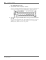
Full-feature input channels 1 through 16 feature an attenuator, four-band parametric
EQ, dynamics processor, delay, and can be assigned to aux sends 1 through 4 and effects
sends 1 and 2. Simplified input channels 17 through 24 feature an attenuator, two-band
parametric EQ, and can be assigned to aux sends 1 and 2 and effects sends 1 and 2.
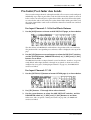
Input channels 1 through 8 and 17 through 24 can be swapped, so that Option I/O digital input signals appear on full-feature channels 1 through 8. Input delays can be used
for microphone-placement compensation, while output delays can be used for
delay-compensation in multi-speaker systems. The number of input channels can be
increased by digitally cascading two 01Vs together. Option I/O digital outputs can be
configured as bus outs, aux sends, input channel direct outs, or stereo outs. So although
the 01V is a four-bus mixer, assigning the four buses and four aux sends, or the channel
direct outs to the Option I/O eight outputs allows eight-track simultaneous recording.
Benefits of a Digital Mixer
You’re probably already familiar with the many benefits offered by digital audio, but
what exactly are the benefits for digital audio mixing? Well, an audio mixer has the job
of combining audio signals from various sources, at differing levels and impedances,
usually into a stereo mix. And it must do this without introducing any new distortions
and noise. Analog mixers do a pretty good job, but even with the best designs, non-linear effects caused by circuit components are unavoidable.
In the digital realm, audio mixing consists of adding and multiplying binary numbers
that represent audio signals. The DSP (Digital Signal Processor) chips used for these
calculations never get their sums wrong, so once past the initial A/D conversion, audio
signals are immune from signal degradation. With the 01V, noise, distortion, and
crosstalk are virtually eliminated, and you’ll hear a new clarity in your mixes.
Once in the digital domain, it makes sense to keep audio data digital, as multiple
AD/DA conversions can degrade signal quality. With an Option I/O interface card, the
01V can be connected directly to a modular digital multitrack recorder, thereby keeping
audio data in the digital domain for both recording and mixing. The final stereo mix
can be transferred to a two-track digital recorder using the 01V’s Coaxial STEREO
OUT.
Onboard stereo multi-effects processors and dynamics processors mean that signals
remain in the digital domain, eliminating unnecessary AD/DA conversions. Digital signal processing is performed using third-generation Yamaha DSPs, as used in the
Yamaha ProR3 Digital Reverberator.
01V—Owner’s Manual
Key Feature Discussion
5
01V Sonic Performance
The 01V’s linear 20-bit 128-times oversampling A/D converters provide a typical
dynamic range of 105 dB. The STEREO OUT features 20-bit 8-times oversampling
D/A converters, while the MONITOR OUT and OMNI OUTs feature 18-bit 8-times
oversampling D/A converters. Oversampling techniques effectively increase the internal sampling rate, so side effects caused by steep low-pass filters, used to filter out sampling frequency components during D/A conversion, are virtually eliminated.
Consequently, audio signal integrity is maintained from input through to output.
The 01V can generate the industry standard sampling rate of 44.1 kHz, or synchronize
to an external wordclock source from 44.1 kHz –10% to 48 kHz +6%.
Four-band Parametric EQ & Library
Input channels 1 through 16, the stereo output, aux sends, and effects returns all feature
four-band fully parametric EQ, with variable gain, frequency, Q, and bypass. Input
channels 17 through 24 feature a simplified two-band parametric EQ. High and low EQ
bands can be used as shelving, peaking, or HPF and LPF, respectively. See “EQ” on page
61 for more information.
EQ settings can be stored in the EQ library as programs, or with all mix settings in mix
scenes. The EQ library consists of 40 preset programs and 40 user programs. User programs allow you to store frequently used EQ settings, which can be titled for easy identification. The unique collection of preset EQ programs are designed for specific
applications and instruments, and provide a good reference and starting point when
making EQ adjustments. See “EQ Library” on page 67 for more information.
Motorized Faders
The 01V features 15 motorized 60 mm faders that move automatically when a mix
scene is recalled, providing a clear and visual indication of fader levels. A fade time of
up to 25 seconds can be set for each mix scene individually. Faders can be grouped
together in one of three fader groups for multiple fader control. See “Grouping Faders”
on page 55 for more information. Faders on paired channels move simultaneously. See
“Pairing Input Channels” on page 52 for more information.
01V Faders are multifunction controls, and their exact operation depends on the
selected Fader mode. Input channel faders may be used as channel faders or aux or
effects send controls. The STEREO fader may be used as the stereo output fader or aux
or effects send master level faders. See “Fader Modes” on page 32 for more information.
Faders 1 through 16 and master can be assigned to various internal parameters on
REMOTE page 1, or used as MIDI controllers on REMOTE page 3. See “Assigning Faders & On Buttons” on page 194 and “User Defined MIDI Controllers” on page 238 for
more information.
01V—Owner’s Manual
6
Chapter 1—Welcome to the 01V
Onboard Effects Processors
The 01V has two stereo multi-effects processors onboard: Effect 1 and Effect 2. These
processors provide a wide range of quality effects, including reverb, delay, chorus,
flange, amp simulator, and more. There are 34 different effects types available. The
effects processors are fed by the Effect 1 and Effect 2 buses, and the processed signals are
returned through the effects return channels. Effects can be applied to input channels
1 through 24. Effects return 1 can be fed to Effect 2, and Effects return 2 can be fed to
Effect 1.
Effects settings can be stored in the effects library as programs, or with all mix settings
in mix scenes. The effect library consists of 42 preset programs and 57 user programs.
User programs allow you to store your own effects programs, which can be titled for
easy identification. See “Effects Library” on page 132 for more information.
External effects processors can be patched into the 01V using the aux sends.
Onboard Dynamics Processors
Dynamics processors, providing compressor, gate, ducking, expander, and compander,
are available on input channels 1 through 16, the stereo output, and the aux sends.
That’s equivalent to 22 dynamics processors! Dynamics processors can be self triggering
(i.e., the signal being processed is used as the trigger signal), or triggered by a signal
from another channel.
Dynamics settings can be stored in the dynamics library as programs, or with all mix
settings in mix scenes. The dynamics library consists of 40 preset programs and 40 user
programs. User programs allow you to store your own dynamics programs, which can
be titled for easy identification. See “Dynamics Library” on page 173 for more information.
Option I/O & Digital I/O
The 01V features a single slot for an optional Option I/O card, providing eight digital
inputs (input channels 17 through 24) and eight assignable digital outputs. Option I/O
provides a direct digital connection to modular digital multitrack recorders, with cards
for the following formats: ADAT, Tascam, and AES/EBU. An Option I/O card offering
four analog outputs is also available. See “About Option I/O Cards” on page 216 for
more information. 01V Option I/O cards are not interchangeable with the YGDAI
cards used by the Yamaha 02R and 03D Digital Recording Consoles, such as the
CD8-AT.
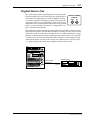
The Coaxial DIGITAL STEREO IN and OUT allow direct connection to stereo digital
recorders and other digital equipment. Digital stereo signals can be routed to the Stereo
bus for cascade operation, or to input channels 13/14 for mixing and processing. See
“Digital Stereo In” on page 213 for more information.
Easy-to-Learn GUI Interface
01V operation is both logical and intuitive. The 320 x 80 dot LCD display uses graphical
icons to represent rotary controls, switches, and faders, and provides a clear indication
of the current mix settings and EQ curves. Dedicated controls allow for quick EQ and
pan adjustments. Mixing functions and configuration settings are organized into display pages. Parameter selection and editing is performed using the [CURSOR],
[ENTER], [–1/DEC] and [+1/INC] buttons, and PARAMETER wheel.
01V—Owner’s Manual
Key Feature Discussion
7
Scene Memories
On many mixers, the only way to store mix settings is with marker pen and masking
tape. With the 01V, however, virtually every mix setting can be stored in a mix scene
using the 01V’s 99 scene memories. Mix scenes can be recalled instantly with just one
button press, or remotely using MIDI Program Change commands. If you work on several projects at a time, you can store the current mix scene so when you return to that
project, you can start again right where you left off. Scene memories also make light
work of night-after-night sound checks. Simply press recall to return to the previous
night’s mix settings. For theater work, scene memories allow accurate and repeatable
sound changes between scenes.
MIDI
In addition to regular MIDI ports, the 01V features a TO HOST port that allows the
01V to be connected directly to a personal computer without a MIDI interface.
MIDI Program Change messages can be used to recall mix scenes, and mix parameters
can be assigned to MIDI Control Change messages for real-time remote control. Mix
parameters that can be stored in mix scenes can be controlled remotely using MIDI System Exclusive messages. Scene memory, library, and setup data can be transferred to a
MIDI data filer, computer, or another 01V for backup and archive using MIDI Bulk
Dump. See “MIDI” on page 221 for more information.
When REMOTE page 2 is displayed, the 01V’s [SEL] and [ON] buttons can be used to
control recorders that support MMC (MIDI Machine Control) commands (stop, play,
rewind, forward, and record). When REMOTE page 3 is displayed, faders, [SOLO] &
[ON] buttons function as assignable MIDI Controllers.
01V—Owner’s Manual
Getting Started
9
Getting Started
2
In this chapter...
01V System Example . . . . . . . . . . . . . . . . . . . . . . . . . . . . . . . . . . . . . . . . . . . . . .
Important Wordclock Information . . . . . . . . . . . . . . . . . . . . . . . . . . . . . . . . . .
Connecting the Power Cord . . . . . . . . . . . . . . . . . . . . . . . . . . . . . . . . . . . . . . . .
Turning On the 01V . . . . . . . . . . . . . . . . . . . . . . . . . . . . . . . . . . . . . . . . . . . . . . .
Turning Off the 01V . . . . . . . . . . . . . . . . . . . . . . . . . . . . . . . . . . . . . . . . . . . . . . .
10
11
11
11
11
01V—Owner’s Manual
10
Chapter 2—Getting Started
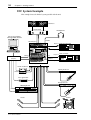
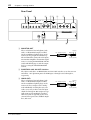
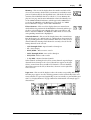
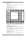
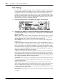
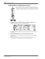
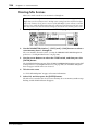
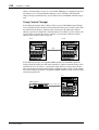
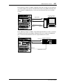
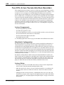
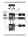
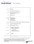
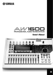
01V System Example
This example shows the kind of system possible with the 01V.
Monitors
Power Amp
Headphones
Personal computer
running MIDI software
PHONES
MONITOR OUT
PHANTOM +48V
OFF ON
PHANTOM +48V
OFF ON
INPUT (BAL)
13
15
14
16
–10dBV (UNBAL)
L
Digital in
R
IN
OUT
Digital multitrack
2TR
PHONES
PAD
26dB
26dB
26dB
26dB
26dB
26dB
26dB
26dB
26dB
26dB
26dB
26dB
–16
–60
+10 GAIN –34
–16
–60
+10 GAIN –34
–16
–60
+10 GAIN –34
–16
–60
+10 GAIN –34
–16
–60
+10 GAIN –34
–16
–60
+10 GAIN –34
–16
–60
+10 GAIN –34
–16
–60
+10 GAIN –34
–16
–60
+10 GAIN –34
–16
–60
+10 GAIN –34
–16
–60
+10 GAIN –34
–16
–60
+10 GAIN –34
1
2
3
4
5
6
7
8
9
10
11
12
15/16
2TR IN
+10
GAIN
–20
13/14
+10
GAIN
MONITOR
2TR IN
–20
15/16
0
LEVEL
10
0
MONITOR
OUT
LEVEL
10
PHONES
OPTION I/O
DIGITAL MIXING CONSOLE
UTILITY
MIDI
SETUP
VIEW
EQ/ATT
Ø/DELAY
PAN/
ROUTING
PAN
FUNCTION
DYNAMICS
AUX 1
Serial port
AUX 2
REMOTE
AUX 3
–6
–9
–12
–15
HI-MID
F
F
G
1 RETURN 2
Digital out
–18
–24
–30
LO-MID
G
EFFECT 2 OPTION I/O
CLIP
–3
MEMORY
FADER MODE
EFFECT 1
8-TRACK DIGITAL
L STEREO R
EQ HIGH
PAN
–36
–42
–48
LOW
SELECTED CHANNEL
AUX 4
HOME
1
2
3
17
SEL
18
SEL
19
SEL
20
SEL
21
SEL
22
SEL
23
SEL
24
SEL
SEL
SEL
SEL
SEL
SEL
SEL
SOLO
SOLO
SOLO
SOLO
SOLO
SOLO
SOLO
SOLO
SOLO
SOLO
SOLO
SOLO
SOLO
SOLO
ON
ON
ON
ON
4
ON
5
ON
6
ON
7
ON
8
ON
9
10
ON
ON
11
12
ON
13/14 15/16
ON
ON
STEREO
MASTER
SEL
ON
MIDI IN
1 RETURN 2
SEL
SEL
SOLO
SOLO
ON
ON
–1/DEC
SOLO
MEMORY
+1/INC
PARAMETER
OUT
Digital in
DAT recorder
00.00.00.00
MIDI
interface
6
6
6
6
6
6
6
6
6
6
6
6
6
6
0
0
–10
–5
0
0
0
0
0
0
0
0
0
0
0
0
0
–15
5
5
5
5
5
5
5
5
5
5
5
5
5
5
10
10
10
10
10
10
10
10
10
10
10
10
10
10
20
20
20
20
20
20
20
20
20
20
20
20
20
20
–20
CURSOR
–30
–40
–50
40
60
MIDI OUT
40
60
40
60
40
60
40
60
40
60
40
60
40
60
40
60
40
60
40
60
40
60
40
60
40
60
–70
–
DIGITAL STEREO
COAXIAL
DAT
ENTER
1
2
3
4
5
6
7
8
17
18
19
20
21
22
23
24
9
10
11
12
13/14
15/16
STEREO
MASTER
IN
Digital out
MIC/LINE inputs 1–16
Drum machine
Guitar processor
MIDI IN
Tone generator
MIDI IN
Bass processor
MIDI keyboard
MIDI IN
MIDI OUT
Vocals
01V—Owner’s Manual
Drums
11
Important Wordclock Information
Important Wordclock Information
Unlike analog audio equipment, digital audio equipment must be wordclock synchronized when digital audio is transferred from one device to another. See “About Wordclocks” on page 206 for more information.
If the 01V is the only digital audio device in your system, no special wordclock settings
are required, and the 01V synchronizes to its own internal wordclock. Add a DAT
recorder or digital multitrack recorder, however, and the system must be configured so
that digital audio equipment synchronizes to a common wordclock source. The “System Examples” on page 241 show how to configure wordclock settings with a variety of
digital audio equipment.
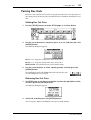
Connecting the Power Cord
Warning: Turn off all equipment before making any connections.
Connect the 01V power cord to a suitable AC wall outlet, one that conforms to the
power supply requirements stated on the rear panel of the 01V.
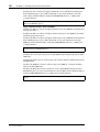
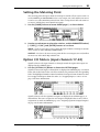
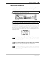
Turning On the 01V
POWER
ON/
OFF
Always turn on your audio equipment in the following order:
1. Sound sources
2. 01V
3. Monitor amplifier
To turn on the 01V, press the 01V POWER switch located on the rear panel.
When turned on, the 01V startup screen appears for a few seconds, and then the display
page selected when the 01V was last turned off appears.
Turning Off the 01V
Always turn off your audio equipment in the following order:
1. Monitor amplifier
2. 01V
3. Sound sources
To turn off the 01V, press the 01V POWER switch located on the rear panel.
All parameter settings, scene memories, and library programs are stored when the 01V
is turned off.
01V—Owner’s Manual
Touring the 01V
13
Touring the 01V
3
In this chapter...
Top Panel Controls . . . . . . . . . . . . . . . . . . . . . . . . . . . . . . . . . . . . . . . . . . . . . . . . 14
Inputs & Outputs . . . . . . . . . . . . . . . . . . . . . . . . . . . . . . . . . . . . . . . . . . . . . . . . . 20
Block Diagram . . . . . . . . . . . . . . . . . . . . . . . . . . . . . . . . . . . . . . . . . . . . . . . . . . . 24
01V—Owner’s Manual
14
Chapter 3—Touring the 01V
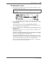
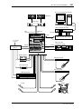
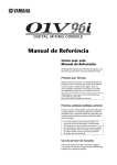
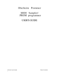
Top Panel Controls
PHANTOM +48V
PHANTOM +48V
OFF ON
OFF ON
INPUT (BAL)
13
15
14
16
–10dBV (UNBAL)
L
R
IN
OUT
2TR
PHONES
PAD
26dB
26dB
26dB
26dB
26dB
26dB
26dB
26dB
26dB
26dB
26dB
26dB
–16
–60
+10 GAIN –34
–16
–60
+10 GAIN –34
–16
–60
+10 GAIN –34
–16
–60
+10 GAIN –34
–16
–60
+10 GAIN –34
–16
–60
+10 GAIN –34
–16
–60
+10 GAIN –34
–16
–60
+10 GAIN –34
–16
–60
+10 GAIN –34
–16
–60
+10 GAIN –34
–16
–60
+10 GAIN –34
–16
–60
+10 GAIN –34
1
2
3
4
5
6
7
8
9
10
11
12
15/16
2TR IN
+10
GAIN
–20
13/14
+10
GAIN
MONITOR
2TR IN
–20
0
LEVEL
10
0
MONITOR
OUT
15/16
LEVEL
10
PHONES
DIGITAL MIXING CONSOLE
L STEREO R
EQ HIGH
UTILITY
MIDI
SETUP
PAN
VIEW
PAN
FUNCTION
DYNAMICS
EQ/ATT
Ø/DELAY
F
F
PAN/
ROUTING
LO-MID
FADER MODE
EFFECT 2 OPTION I/O
AUX 1
AUX 2
REMOTE
AUX 3
–15
–18
–24
–30
–36
–42
MEMORY
G
EFFECT 1
CLIP
–3
–6
–9
–12
HI-MID
G
1 RETURN 2
–48
LOW
SELECTED CHANNEL
AUX 4
HOME
1
2
3
4
5
6
7
8
9
10
11
12
17
SEL
18
SEL
19
SEL
20
SEL
21
SEL
22
SEL
23
SEL
24
SEL
SEL
SEL
SEL
SEL
13/14 15/16
SEL
SEL
SOLO
SOLO
SOLO
SOLO
SOLO
SOLO
SOLO
SOLO
SOLO
SOLO
SOLO
SOLO
SOLO
SOLO
ON
ON
ON
ON
ON
ON
ON
ON
ON
ON
ON
ON
ON
ON
STEREO
MASTER
SEL
ON
1 RETURN 2
SEL
SEL
SOLO
SOLO
ON
ON
–1/DEC
SOLO
MEMORY
+1/INC
PARAMETER
6
6
6
6
6
6
6
6
6
6
6
6
6
6
0
0
0
0
0
0
0
0
0
0
0
0
0
0
0
–10
5
5
5
5
5
5
5
5
5
5
5
5
5
5
10
10
10
10
10
10
10
10
10
10
10
10
10
10
20
20
20
20
20
20
20
20
20
20
20
20
20
20
40
60
40
60
40
60
40
60
40
60
40
60
40
60
40
60
40
60
40
60
40
60
40
60
40
60
40
60
–5
–15
–20
CURSOR
–30
–40
–50
–70
–
ENTER
1
2
3
4
5
6
7
8
17
18
19
20
21
22
23
24
9
10
11
12
13/14
15/16
STEREO
MASTER
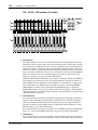
The individual sections of the 01V are explained on the following pages.
01V—Owner’s Manual
15
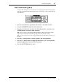
Top Panel Controls
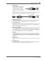
Analog Control Section
1
2
3
PAD
26dB
26dB
26dB
26dB
26dB
26dB
26dB
26dB
26dB
26dB
26dB
26dB
–16
–60
+10 GAIN –34
–16
–60
+10 GAIN –34
–16
–60
+10 GAIN –34
–16
–60
+10 GAIN –34
–16
–60
+10 GAIN –34
–16
–60
+10 GAIN –34
–16
–60
+10 GAIN –34
–16
–60
+10 GAIN –34
–16
–60
+10 GAIN –34
–16
–60
+10 GAIN –34
–16
–60
+10 GAIN –34
–16
–60
+10 GAIN –34
1
2
3
4
5
6
7
8
9
10
11
12
4
15/16
2TR IN
+10
GAIN
–20
13/14
+10
GAIN
–20
15/16
MONITOR
2TR IN
+10
–20
LEVEL
+10
–20
LEVEL
MONITOR
OUT
PHONES
5
6
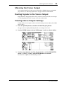
A PAD switches
These switches are used to turn on and off the 26 dB input pads. See “Pad Switches” on
page 41 for more information.
B 15/16–2TR IN Switch
This switch is used to select the signal source for input channels 15 and 16: phone jacks
15 and 16 (15/16) or the 2TR IN phono jacks (2TR IN).
C MONITOR–2TR IN Switch
This switch is used to select the signal source for the monitor out and phones: Monitor
bus (MONITOR) or 2TR IN phono jacks (2TR IN).
D GAIN controls
These controls are used to adjust the gain of the input preamps. See “Setting Input
Channel Gain” on page 41 for more information.
E MONITOR OUT LEVEL control
This control is used to adjust the monitor out level.
F PHONES LEVEL control
This control is used to adjust the phones level.
01V—Owner’s Manual
16
Chapter 3—Touring the 01V
Display, Selected Channel Controls & Meters
DIGITAL MIXING CONSOLE
EQ HIGH
PAN
PAN
FUNCTION
1
MEMORY
HI-MID
F
F
LO-MID
G
G
1 RETURN 2
LOW
L STEREO R
CLIP
–3
–6
–9
–12
–15
–18
–24
–30
–36
–42
–48
4
SELECTED CHANNEL
2
3
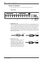
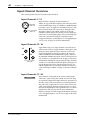
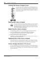
A Display
This 320 x 80 dot LCD display provides clear indication of mix settings and operating
status. As well as showing parameter values numerically, faders and rotary controls are
represented graphically, so you can actually see pan and fader positions. The display
also shows EQ curves and signal level meters. See “Display” on page 28 for more information.
B SELECTED CHANNEL Controls
These controls are used to adjust the pan and EQ of the selected channel. Dedicated
rotary controls for PAN, EQ frequency (F) and EQ gain (G), and EQ [HIGH],
[HI-MID], [LO-MID], and [LOW] buttons make for quick operation. When the EQ
AUTO SCREEN option is turned on, and an EQ control is adjusted, the EQ page
appears automatically. Likewise, for the PANPOT AUTO SCREEN option and PAN
control. See “Setting 01V Preferences” on page 203 for more information.
C Contrast
This control is used to adjust the display contrast. Adjust it so that the display is clear
and easy-to-read from your viewing position. You may need to readjust it when viewing
the display from a different height or angle.
D Stereo Output Meters
These 12-segment LED bar-type meters display the stereo output signal levels.
Parameter Wheel, Cursors & Enter
–1/DEC
+1/INC
PARAMETER
CURSOR
ENTER
These controls are used to navigate around the display pages and edit parameters. See
“Getting Around the User Interface” on page 27 for more information.
01V—Owner’s Manual
Top Panel Controls
17
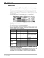
Function Buttons
UTILITY
MIDI
SETUP
VIEW
DYNAMICS
EQ/ATT
Ø/DELAY
PAN/
ROUTING
MEMORY
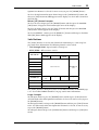
Function buttons are used to access the following function pages. Related pages are
grouped together and can be selected by repeatedly pressing a button. The name of the
selected function and its page number appear in the top-left corner of the display.
Button
Pages
UTILITY
Oscillator, Preferences-1, Preferences-2
MIDI
MIDI Setup, Program Change, Control Change, Bulk, Local Control
SETUP
Word Clock Select, Monitor/Solo Setup, Group, Pair, Dither
VIEW
Channel View, Fader View, CH Copy
DYNAMICS
Dynamics Edit, Dynamics Library
EQ/ATT
EQ Edit, EQ Library
ø/DELAY
Phase, Input Delay 1–8, Input Delay 9–16, Output Delay
PAN/ROUTING
Panpot, Routing, Bus Master, Omni Out Select
MEMORY
Memory, Fade Time, Memory Sort, Recall Safe
Fader Mode Buttons
FADER MODE
EFFECT 1
AUX 1
EFFECT 2 OPTION I/O
AUX 2
AUX 3
REMOTE
AUX 4
HOME
Fader mode buttons are used to select the following fader modes and display pages.
Pressing buttons repeatedly selects the various pages that are available for a mode. The
name of the selected function and its page number appear in the top-left corner of the
display.
Button
Pages
EFFECT 1
Effect1 Edit, Effect1 Library, Effect1 Pre/Post
EFFECT 2
Effect2 Edit, Effect2 Library, Effect2 Pre/Post
OPTION I/O
Option In Meter, Channel Control, Option Out Meter, Option Out
Select, Input Swap
REMOTE
Internal Parameter, MMC Control, User Define
AUX 1
Pre/Post, Aux 1-2 Pan
AUX 2
Pre/Post, Aux 1-2 Pan
AUX 3
Pre/Post, Aux 3-4 Pan
AUX 4
Pre/Post, Aux 3-4 Pan
HOME
Input Meter, Rtn/Output Meter, Omni Out Meter, St Out Meter,
Metering Point
01V—Owner’s Manual
18
Chapter 3—Touring the 01V
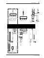
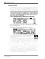
SEL, SOLO, ON buttons & Faders
1
1
2
3
4
5
6
7
8
17
SEL
18
SEL
19
SEL
20
SEL
21
SEL
22
SEL
23
SEL
24
SEL
9
10
11
12
13/14 15/16
SEL
SEL
SEL
SEL
SEL
SEL
SOLO
SOLO
SOLO
SOLO
SOLO
SOLO
SOLO
SOLO
SOLO
SOLO
SOLO
SOLO
SOLO
SOLO
ON
ON
ON
ON
ON
ON
ON
ON
ON
ON
ON
ON
ON
ON
STEREO
MASTER
SEL
5
1 RETURN 2
SEL
SEL
SOLO
SOLO
ON
ON
SOLO
6
2
3
6
6
6
6
6
6
6
6
6
6
6
6
6
6
0
0
0
0
0
0
0
0
0
0
0
0
0
0
5
5
5
5
5
5
5
5
5
5
5
5
5
5
10
10
10
10
10
10
10
10
10
10
10
10
10
10
20
20
20
20
20
20
20
20
20
20
20
20
20
20
40
60
40
60
40
60
40
60
40
60
40
60
40
60
40
60
40
60
40
60
40
60
40
60
40
60
40
60
ON
0
–5
4
–10
–15
–20
–30
–40
–50
1
2
3
4
5
6
7
8
17
18
19
20
21
22
23
24
9
10
11
12
13/14
15/16
–70
–
STEREO
MASTER
A SEL buttons
The [SEL] buttons are used to select channels for parameter editing: input channels 1
through 24, effects returns 1 and 2, aux sends 1 through 4, effects sends 1 and 2, and the
stereo output. Press [SEL] button 13/14 or 15/16 repeatedly to select input channels 13
and 14 or 15 and 16, respectively. Since most functions on input channels 13 and 14
(likewise 15 and 16) are linked together, the only time you’ll need to select either channel 13 or channel 14 (likewise 15 or 16) is to set the Phase or Pan for a channel individually. The number of the selected channel appears in the lower-right corner of the
display. See “Display” on page 28 for more information.
Normally, [SEL] buttons 1 through 8 select channels 1 through 8. When the [OPTION
I/O] button is pressed, however, they select input channels 17 through 24, which are
only available when an Option I/O card is installed. See “SEL Buttons” on page 32 for
more information. The [SEL] buttons 1 through 6 are also used to transmit MMC
(MIDI Machine Control) Locate commands when REMOTE page 2 is displayed.
Finally, [SEL] buttons are also used to make and break channel pairs (“Pairing Input
Channels” on page 52) and fader and mute groups (“Grouping Faders” on page 55 and
“Grouping Mutes” on page 56).
B SOLO buttons
The [SOLO] buttons are used to solo channels: input channels 1 through 16 and effects
returns 1 and 2. Normally, [SOLO] buttons 1 through 8 select channels 1 through 8.
When the [OPTION I/O] button is pressed, however, they select input channels 17
through 24, which are only available when an Option I/O card is installed. See “Solo
Buttons” on page 33 for more information.
The [SOLO] buttons 1 through 16 can also be used as MIDI controllers on REMOTE
page 3. See “User Defined MIDI Controllers” on page 238 for more information.
C ON buttons
The [ON] buttons are used to turn channels on and off: input channels 1 through 24,
effects returns 1 and 2, aux sends 1 through 4, effects sends 1 and 2, and the stereo out-
01V—Owner’s Manual
Top Panel Controls
19
put. Normally, [ON] buttons 1 through 8 select channels 1 through 8. When the
[OPTION I/O] button is pressed, however, they select input channels 17 through 24,
which are only available when an Option I/O card is installed. See “ON Buttons” on
page 34 for more information.
The [ON] buttons 1 through 16 and master can be assigned to various internal parameters on REMOTE page 1, or used as MIDI controllers on REMOTE page 3. See
“Assigning Faders & On Buttons” on page 194 and “User Defined MIDI Controllers”
on page 238 for more information.
D Faders
Depending on the selected fader mode, the 01V’s 60 mm motorized faders are used to
control channel levels, aux send levels, or effects sends levels. Normally, faders 1
through 8 control channels 1 through 8. When the [OPTION I/O] button is pressed,
however, they control input channels 17 through 24, which are only available when an
Option I/O card is installed. See “Faders (plus Return Rotary Controls)” on page 35 for
more information.
Faders 1 through 16 and master can be assigned to various internal parameters on
REMOTE page 1, or used as MIDI controllers on REMOTE page 3. See “Assigning Faders & On Buttons” on page 194 and “User Defined MIDI Controllers” on page 238 for
more information.
E RETURN Controls
The RETURN controls are used to adjust the effects return levels, and their positions
are displayed in the lower-left corner of the display.
F SOLO Status Indicator
The SOLO status indicator lights up when a channel is soloed.
01V—Owner’s Manual
20
Chapter 3—Touring the 01V
Inputs & Outputs
Input and output connectors are located on the top and rear panels.
Top Panel
PHANTOM +48V
PHANTOM +48V
OFF ON
OFF ON
INPUT (BAL)
13
15
14
16
–10dBV (UNBAL)
L
R
IN
OUT
2TR
PHONES
1
2
34 5
A INPUT (BAL) 1–12
Input channels 1 through 12 feature balanced XLR-3-31-type and balanced phone jack
connectors, both with a nominal input range of –60 dB to +10 dB. Phantom powering
(+48 V) is supplied to the XLR connectors, with master on/off switches for connectors
1 through 6 and 7 through 12. Phone jacks, which can also be used with unbalanced
phone plugs, have priority over the XLR-type connectors, so when a phone plug is
inserted, the XLR-type connector is disconnected. With their high sensitivity and 26 dB
PAD switches, these inputs can handle a wide range of signals, from condenser microphones to “hot” line levels.
Male XLR plug
1 (ground)
3 (cold)
Tip (hot)
1/4" TRS phone plug
2 (hot)
Ring (cold)
Sleeve (ground)
B INPUT (BAL) 13–16
Input channels 13 through 16 feature balanced phone jack connectors, with a
nominal input range of –20 dB to +10 dB.
These inputs are designed for use with
line-level sources, and can also be used
with unbalanced phone plugs. The stereo
outputs of an external effects processor or
other stereo device can be connected here.
01V—Owner’s Manual
Tip (hot)
1/4" TRS phone plug
Ring (cold)
Sleeve (ground)
21
Inputs & Outputs
C 2TR IN
These are phono jacks with a –10 dBV nominal input level.
Signals input here can be monitored via the monitor out and
phones when the MONITOR–2TR IN switch is set to
2TR IN. The stereo outputs of a master recorder can be connected here for confidence monitoring and master playback.
By setting the 15/16–2TR IN switch to 2TR IN, 2TR IN signals can be fed to input channels 15 and 16 for mixing with
other signals.
Phono plug
Tip
Sleeve
D 2TR OUT
These are phono jacks with a –10 dBV nominal output level.
The 2TR OUT signal is the same as the stereo out signal. A
cassette deck, DAT, or MiniDisc deck connected here can be
used to record the stereo mix.
Phono plug
Tip
Sleeve
E PHONES
This is a stereo (TRS) phone jack, to
which a pair of stereo headphones can be
connected for monitoring. The phones
signal is the same as the monitor out signal, and the level is set using the phones
level control.
Tip (left)
1/4" TRS phone plug
Ring (right)
Sleeve (ground)
01V—Owner’s Manual
22
Chapter 3—Touring the 01V
Rear Panel
1 2
3
4
CH 7-12
7
8
ON OFF
MONITOR OUT
STEREO OUT
R +4dB (BAL) L
OMNI OUT
+4dB (BAL)
L
6
CH 1-6
PHANTOM +48V
ON OFF
R
52
+4dB (BAL)
4
3
2
DIGITAL STEREO
COAXIAL
1
OUT
POWER
ON/
MIDI
THRU
TO HOST
OUT
IN
IN
OPTION I/O
OFF
9
J
A MONITOR OUT
These are balanced 1/4-inch phone jacks
with a +4 dB nominal output level. Balanced or unbalanced phone plugs can be
connected. They output the monitor signals and should be connected to the inputs
on a monitor amplifier. The monitor signal
source is set using the MONITOR–2TR IN
switch and SETUP page 2, and the output
level is set using the MONITOR LEVEL
control.
Tip (hot)
1/4" TRS phone plug
Ring (cold)
Sleeve (ground)
B PHANTOM +48V ON–OFF Switches
The CH 1–6 and CH 7–12 PHANTOM +48V ON–OFF switches are used to turn on
and off the +48 V phantom power for XLR inputs 1 through 6 and 7 through 12,
respectively.
C OMNI OUTs
These are balanced 1/4-inch phone jacks
with a +4 dB nominal output level. Balanced or unbalanced phone plugs can be
connected. These outputs can be configured individually as analog bus outs, aux
sends, stereo outs, or direct outs for input
channels 1 through 16. Bus outputs are typically connected to multitrack recorders,
while aux sends are typically used to feed
external effects processors, foldback amplifiers, and so on.
01V—Owner’s Manual
Tip (hot)
1/4" TRS phone plug
Ring (cold)
Sleeve (ground)
Inputs & Outputs
23
D STEREO OUT
These are balanced XLR-3-32-type
connectors with a +4 dB nominal
output level. They are wired pin
1–ground, pin 2–hot (+), and pin
3–cold (–). They output the main stereo mix.
Female XLR plug
2 (hot)
3 (cold)
1 (ground)
If you need to connect the balanced ST OUT to an unbalanced phone jack input, use a
cable with the following wiring scheme (i.e., XLR pins 3 and 1 linked).
Tip (hot)
1/4" phone plug
Sleeve (ground)
Female XLR plug
2 (hot)
3 (cold)
1 (ground)
E DIGITAL STEREO OUT
This phono jack outputs the main stereo mix as Coaxial format 24-bit digital audio,
allowing digital transfer to a DAT, MiniDisc deck, or other digital recorder.
F DIGITAL STEREO IN
This phono jack accepts 24-bit Coaxial format digital audio. Signals input here can be
fed directly to the Stereo bus for stereo cascade operation (i.e., two mixers working
together), or to input channels 13 and 14.
G MIDI IN, OUT, THRU
These are standard MIDI IN, OUT, and THRU ports and are used to connect the 01V
to other MIDI equipment for remote control and data backup. The MIDI IN port
receives MIDI messages, while the MIDI OUT port transmits them. The MIDI THRU
port transmits all MIDI messages received at the MIDI IN port.
H TO HOST
This 8-pin mini DIN port is used to connect the 01V to a personal computer for use
with MIDI software. It eliminates the need for a computer MIDI interface, and together
with the MIDI ports allows the 01V to be used as a MIDI interface for other MIDI
equipment.
I POWER switch
This switch is used to turn on and off the 01V. It’s recessed to prevent accidental operation.
J OPTION I/O slot
An Option I/O card can be installed here, providing access to the 01V’s eight digital
inputs and outputs. See “About Option I/O Cards” on page 216.
01V—Owner’s Manual
01V—Owner’s Manual
16
INPUT
(BAL)
15
DIGITAL
STEREO
IN
14
INPUT
(BAL)
13
1-12
INPUT
(BAL)
HA
GAIN
HA
HA
GAIN
HA
AD
AD
AD
from 2TR IN
AD
AD
+48V
15/16
2TR IN
PHANTOM
GAIN
HA
1-6,
7-12
De-emphasis
26dB
Pad
to
ATT
Meter
FLIP
ATT
ATT
4-Band
PEQ
4-Band
PEQ
4-Band
PEQ
4-Band
PEQ
4-Band
PEQ
Dynamics
Dynamics
Meter
Dynamics
Meter
ON
ON
CH Fader
CH Fader
EFF2
EFF1
AUX4
AUX3
AUX2
AUX1
PAN*
OUTPUT
SELECT
ON/OFF
to
to MONI
to MONI
OUTPUT
SELECT
AUX/EFF
PRE/POST
to
AUX/EFF
PRE/POST
EFF2
EFF1
AUX4
AUX3
AUX2
AUX1
PAN
*PAN: INDIVIDUAL/GANG/INV. GANG
Same as INPUT 14
Same as INPUT 13
Delay
Delay
Meter
Delay
Meter
BUS
AUX EFF ST
1 2 3 4 1 2 3 4 1 2 L R
4-Band
PEQ
PAN
4-Band
PEQ
4-Band
PEQ
Meter
Meter
Effect send 1/2
master fader
DIGITAL
STEREO
IN
AUX
master fader
ON
ON
ON
BALANCE
ON
BUS
master fader
from
Dynamics
Meter
TO ST
Dynamics
Dynamics
Meter
ST CASCADE IN
1-4
AUX
1-4
1-4
BUS
1-4
to
to
to
Dither
DA
DA
STEREO OUT
to INTERNAL
EFFECT 1, 2
LISTEN
LISTEN
Meter
LISTEN
Meter
LISTEN
Delay
Delay
Meter
OUTPUT
SELECT
OUTPUT
SELECT
OUTPUT
SELECT
2TR OUT
to
MONITOR
MONI
L R
DIGITAL
STEREO
OUT
STEREO
OUT
R
L
R
L
24
Chapter 3—Touring the 01V
Block Diagram
Option I/O
IN
De-emphasis
or DC Cut
Unchanged
This section is available only when
an optional Option I/O card is installed.
17-24
INPUT
1-8
(BAL)
Waveform
OSC
Meter
100Hz
1kHz
10kHz
PINK
BURST
from EFF2
from EFF1
Meter
Internal
Effect 2
Internal
Effect 1
Meter
SWAP
Meter
LEVEL
ATT
4-Band
PEQ
4-Band
PEQ
2-Band
PEQ
Meter
Unchanged
EFF RTN
Rotary
EFF1
AUX/EFF
PRE/POST
EFF2
AUX4
AUX3
AUX2
AUX1
PAN*
AUX/EFF
PRE/POST
EFF2
EFF1
AUX2
AUX1
PAN
*PAN: INDIVIDUAL/GANG/INV. GANG
ON
Same as Effect 1
ON
ON
CH Fader
BUS
AUX EFF ST
1 2 3 4 1 2 3 4 1 2 L R
from
MONI
CH 15
CH 16
AUX 4
CH 1
CH 2
BUS 4
AUX 1
STEREO L
STEREO R
BUS 1
CH 15
CH 16
AUX 4
CH 1
CH 2
2TR IN
R
L
to INPUT 15, 16
MONI
TRIM
from
from
BUS 4
AUX 1
STEREO L
STEREO R
BUS 1
MONO
OMNI OUT
Select
Option I/O
Output
Select
DA
DA
Delay
Meter
Meter
Meter
Meter
MONITOR
2TR IN
DA
Option
I/O
Dither
LEVEL
LEVEL
1-4
OMNI
OUT
Option I/O
1-8
OUT
MONITOR
OUT
PHONES
R
L
Block Diagram
25
01V—Owner’s Manual
Getting Around the User Interface
27
Getting Around the User Interface
4
In this chapter...
About the User Interface . . . . . . . . . . . . . . . . . . . . . . . . . . . . . . . . . . . . . . . . . . .
Display . . . . . . . . . . . . . . . . . . . . . . . . . . . . . . . . . . . . . . . . . . . . . . . . . . . . . . . . . .
Display Elements . . . . . . . . . . . . . . . . . . . . . . . . . . . . . . . . . . . . . . . . . . . . . . . . . .
Cursor Buttons . . . . . . . . . . . . . . . . . . . . . . . . . . . . . . . . . . . . . . . . . . . . . . . . . . .
PARAMETER Wheel . . . . . . . . . . . . . . . . . . . . . . . . . . . . . . . . . . . . . . . . . . . . . .
–1/DEC & +1/INC Buttons . . . . . . . . . . . . . . . . . . . . . . . . . . . . . . . . . . . . . . . . .
ENTER Button . . . . . . . . . . . . . . . . . . . . . . . . . . . . . . . . . . . . . . . . . . . . . . . . . . .
Fader Modes . . . . . . . . . . . . . . . . . . . . . . . . . . . . . . . . . . . . . . . . . . . . . . . . . . . . .
Title Edit Dialog Box . . . . . . . . . . . . . . . . . . . . . . . . . . . . . . . . . . . . . . . . . . . . . .
28
28
30
31
31
31
31
32
37
01V—Owner’s Manual
28
Chapter 4—Getting Around the User Interface
About the User Interface
Thanks to a user-friendly interface, 01V operation is both logical and intuitive. The 320
x 80 dot LCD display provides clear indication of mix settings and operating status,
while dedicated SELECTED CHANNEL controls allow for quick EQ and pan adjustments. Operation of the multifunction faders depends on the selected Fader mode.
Mixing functions and configuration settings are organized into display pages, with up
to five related pages being grouped together. For example, the MIDI Setup and Program
Change pages are grouped together under MIDI. Parameter selection and editing is carried out using the [CURSOR], [ENTER], [–1/DEC] and [+1/INC] buttons, and
PARAMETER wheel, which is detented for precise and accurate editing.
Display
The 320 x 80 dot LCD display provides clear indication of mix settings and operating
status. As well as showing parameter values numerically, faders and rotary controls are
represented graphically, so you can actually see pan and fader positions. The display
also shows EQ curves and signal level meters. The various sections of the display are
explained below.
Page area
Function
Memory
Effects
Returns
Selected channel
Function—This area of the display shows the name of the function
selected using the Function and Fader mode buttons. Functions are
divided into pages, which are identified by numbered tabs, as shown
here. In this example, page 1 of the VIEW function is selected. The following functions can be selected.
01V—Owner’s Manual
Function Buttons
Fader Mode Buttons
UTILITY
EFFECT 1
MIDI
EFFECT 2
SETUP
OPTION I/O
VIEW
REMOTE
DYNAMICS
AUX 1
EQ/ATT
AUX 2
ø/DELAY
AUX 3
PAN/ROUTING
AUX 4
MEMORY
HOME
Display
29
Memory—This area of the display shows the number and title of the
selected scene memory, whether that scene memory is read only or write
protected (indicated by the closed padlock icon), and whether or not the
contents of the Edit Buffer have been edited. See “Scene Memory Display Area” on page 185 for more information. Also in the Memory area
are the MIDI and HOST indicators, which appear when MIDI data is
received at the MIDI IN or TO HOST port, respectively. See “MIDI
Receive Indicators” on page 224 for more information.
Effects Returns—This area of the display shows two control icons,
which indicate the positions of the RETURN level controls, and the type
of effects selected for the two onboard effects processors: Effect 1 and
Effect 2. When the EFFECT 1 or EFFECT 2 Fader mode is selected, the
corresponding control icon is highlighted.
Selected channel—This area of the display shows three control icons:
Pan, EQ frequency (F), and EQ gain (G), which indicate the pan, EQ frequency, and EQ gain of the selected channel. Below these is the selected
channel indicator, showing which channel is currently selected. The following channels can be selected.
• CH1 through CH24—Input channels 1 through 24
• ST—Stereo output
• RTN1, RTN2—Effects returns 1 and 2
• AUX1 through AUX4—Aux sends 1 through 4
• EFF1, EFF2—Effects sends 1 and 2
• 1–16, MAS—Remote function channels
When channels 13 through 16, the effects return channels, or paired input
channels from 1 through 12 are selected, dotted lines appear to the right
of these control icons when an odd or left channel is selected. Similarly,
dotted lines appear to the left, as shown here, when an even or right channel is selected.
Page area—This area of the display is where the various setup, utility, and mixing
function pages appear. As well as showing parameter values numerically, faders and
rotary controls are represented graphically, so you can actually see pan and fader positions. See “Display Elements” on page 30 for more information. An example page is
shown below.
01V—Owner’s Manual
30
Chapter 4—Getting Around the User Interface
Display Elements
This section explains the various control elements that appear on display pages.
Switches
Switches appear as boxes with a shadowed outline (i.e., a thicker outline on the right side and bottom).
Simple on/off-type switches are highlighted when they are turned
on. In this example, the [ST] switch is on.
The labels inside some switches change when they turned on and
off, as these phase switches show.
For option-type switches, only one switch can be on at a time. In this
example, the monitor source can be set to either stereo out or ST
CASCADE IN, but not both.
To operate a switch, use the cursor buttons to select it, and the [ENTER] button or
[–1/DEC] and [+1/INC] buttons to turn it on or off.
Rotary Controls
Some parameters appear as rotary controls, as this example from
the PANPOT page shows. To adjust a rotary control, use the cursor
buttons to select it and use the PARAMETER wheel or [–1/DEC]
and [+1/INC] buttons to adjust it.
Parameter Boxes
Some parameters appear in parameter boxes
(i.e., dotted-line boxes), as this example from
the EFFECT1 EDIT page shows. To adjust a
parameter box parameter, use the cursor buttons to select it, and the PARAMETER wheel or
[–1/DEC] and [+1/INC] buttons to set it.
Parameter boxes that require you to confirm
new settings flash until you press the [ENTER]
button.
Faders
Pages such as VIEW and BUS MASTER display faders graphically. To adjust a fader, use the cursor buttons to select it, and the
PARAMETER wheel or [–1/DEC] and [+1/INC] buttons to set
it. Fader knobs appear highlighted when set to the nominal position.
01V—Owner’s Manual
Nominal
31
Cursor Buttons
Cursor Buttons
The cursor buttons are used to move the cursor
around the display pages, selecting parameters and
options. The cursor appears as a flashing box, making
it easy to see which parameter or option is currently
selected. Holding down a cursor button moves the
cursor continuously in the respective direction.
CURSOR
PARAMETER Wheel
The PARAMETER wheel is used to adjust parameter values, scroll
through scene memory and library programs, and position the
cursor when titling scene memories, effects programs, and so on.
Its detented action gives it a positive feel, allowing quick and accurate parameter editing. Turning it clockwise increases parameter
values; turning it counterclockwise decreases them.
PARAMETER
–1/DEC & +1/INC Buttons
Like the PARAMETER wheel, the [–1/DEC] and [+1/INC]
–1/DEC
+1/INC
PARAMETER
buttons are used to adjust parameter values, scroll through
scene memory and library programs, and position the cursor when titling scene memories, effects programs, and so
on. The [–1/DEC] button is used to decrement values, while the [+1/INC] button is
used to increment them. Holding down the [–1/DEC] or [+1/INC] button sweeps
through a parameter’s adjustable range. When titling memories or programs, the
[–1/DEC] button is used to toggle between uppercase, lowercase, and numerals, while
the [+1/INC] button is used to insert spaces.
ENTER Button
The [ENTER] button is used to activate parameter settings selected using
ENTER
the [CURSOR] buttons, and set on/off-type parameters, such as EQ
ON/OFF. It’s also used to confirm settings and enter characters when titling
scene memories, effects programs, and so on. On the EQ page, the [ENTER] button is
used solely to turn the EQ on and off.
01V—Owner’s Manual
32
Chapter 4—Getting Around the User Interface
Fader Modes
The 01V [SEL], [SOLO], and [ON] buttons, channel faders, and STEREO (MASTER)
fader are multifunction controls, and their exact operation depends on the selected
Fader mode. Operation of these controls is shown in the following tables.
SEL Buttons
The [SEL] buttons are used to select channels for EQ, Pan, Dynamics, and Routing
operations. The following channels can be selected:
• CH1 through CH24—Input channels 1 through 24
• ST—Stereo output
• RTN1, RTN2—Effects returns 1 and 2
• AUX1 through AUX4—Aux sends 1 through 4
• EFF1, EFF2—Effects sends 1 and 2
• 1–16, MAS—Remote function channels
The [SEL] buttons are also used to make and release channel pairs and fader and mute
groups (“Grouping Faders” on page 55 and “Grouping Mutes” on page 56).
SEL button
Fader Mode
1–8
[17–24]
9–12
13/14
15/16
STEREO
[MASTER]
HOME
STEREO OUT
select
AUX 1
AUX 1
master select
AUX 2
AUX 2
master select
AUX 3
AUX 3
master select
CH 1–16 select
AUX 4
AUX 4
master select
EFFECT 1
EFFECT 1
master select
EFFECT 2
EFFECT 2
master select
OPTION I/O
CH 17–24
select
REMOTE 1
REMOTE 2
REMOTE 3
—
—
RETURN 1/2
select
STEREO select
Internal parameter assign select
MMC (1–6)
RETURN 1/2
—
—
User defined MIDI controller select
—
Input Channel [SEL] button Examples
To select the EQ function for input channel 3, press the [HOME] button, and then press
[SEL] button 3 (CH3 appears in the bottom right corner of the display). Use the
SELECTED CHANNEL F and G controls to adjust the EQ. (If a fader mode other than
Option I/O or Remote is selected, it’s not necessary to press the [HOME] button.)
To select the Pan function for input channel 13, press the [HOME] button, and then
press [SEL] button 13/14 repeatedly until CH13 appears on the display. Use the
SELECTED CHANNEL PAN control to adjust the pan. Since most functions on input
channels 13 and 14 (likewise 15 and 16) are linked, the only time you’ll need to select
these channels individually is to set the Phase or Pan. (If a fader mode other than
01V—Owner’s Manual
Fader Modes
33
Option I/O or Remote is selected, it’s not necessary to press the [HOME] button.)
To select the EQ function for input channel 20, press the [OPTION I/O] button, and
then press [SEL] button 20 (CH20 appears on the display). Use the F and G controls to
adjust the EQ.
Master [SEL] Button Examples
To select the stereo output, press the [HOME] button, and then press the MASTER
[SEL] button (ST appears in the bottom right corner of the display).
To select the AUX 1 master, press the [AUX 1] button, and then press the MASTER
[SEL] button (AUX1 appears on the display).
To select the EFFECT 1 master, press the [EFFECT 1] button, and then press the MASTER [SEL] button (EFF1 appears on the display).
Solo Buttons
The [SOLO] buttons are used to solo channels for monitoring. See “Solo Setup” on
page 80 for more information. The following channels can be soloed:
• CH1 through CH24—Input channels 1 through 24
• RTN1, RTN2—Effects returns 1 and 2
SOLO button
Fader Mode
1–8
[17–24]
9–12
13/14
15/16
RETURN 1/2
HOME
AUX 1
AUX 2
AUX 3
RETURN 1/2
solo
CH 1–16 solo
AUX 4
EFFECT 1
EFFECT 2
OPTION I/O
CH 17–24
solo
—
—
REMOTE 1
—
REMOTE 2
—
REMOTE 3
User defined MIDI controller
—
—
The [SOLO] buttons 1 through 16 can be used as MIDI controllers on REMOTE page
3. See “User Defined MIDI Controllers” on page 238 for more information.
Usage Examples
To solo input channel 3, press the [HOME] button, and then press [SOLO] button 3.
(If a fader mode other than Option I/O or Remote is selected, it’s not necessary to press
the [HOME] button.)
To solo input channels 13/14, press the [HOME] button, and then press [SOLO] button
13/14. (If a fader mode other than Option I/O or Remote is selected, it’s not necessary
to press the [HOME] button.)
To solo input channel 20, press the [OPTION I/O] button, and then press [SOLO] button 20.
01V—Owner’s Manual
34
Chapter 4—Getting Around the User Interface
ON Buttons
The [ON] buttons are used to turn channels on or off. They work with the following
channels:
• CH1 through CH24—Input channels 1 through 24
• ST—Stereo output
• RTN1, RTN2—Effects returns 1 and 2
• AUX1 through AUX4—Aux sends 1 through 4
• EFF1, EFF2—Effects sends 1 and 2
The bus outs can be turned on or off on PAN/ROUT page 4.
ON button
Fader Mode
1–8
[17–24]
9–12
13/14
15/16
STEREO
[MASTER]
HOME
STEREO OUT
On/Off
AUX 1
AUX 1
master On/Off
AUX 2
AUX 2
master On/Off
AUX 3
AUX 3
master On/Off RETURN 1/2
On/Off
AUX 4
master On/Off
CH 1–16 On/Off
AUX 4
EFFECT 1
EFFECT 1
master On/Off
EFFECT 2
EFFECT 2
master On/Off
OPTION I/O
CH 17–24
On/Off
REMOTE 1
REMOTE 2
REMOTE 3
—
STEREO OUT
On/Off
—
Assigned internal parameters
MMC (1–6)
RETURN 1/2
—
—
User defined MIDI controllers
—
On buttons 1 through 16 and master can be assigned to various internal parameters on
REMOTE page 1, or used as MIDI controllers on REMOTE page 3. See “Assigning Faders & On Buttons” on page 194 and “User Defined MIDI Controllers” on page 238 for
more information.
Input Channel [ON] button Examples
To turn on or off input channel 3, press the [HOME] button, and then press [ON] button 3. (If a fader mode other than Option I/O or Remote is selected, it’s not necessary
to press the [HOME] button.)
To turn on or off input channels 13/14, press the [HOME] button, and then press [ON]
button 13/14. (If a fader mode other than Option I/O or Remote is selected, it’s not necessary to press the [HOME] button.)
To turn on or off input channel 20, press the [OPTION I/O] button, and then press
[ON] button 20.
Master [ON] Button Examples
To turn on or off the stereo output, press the [HOME] button, and then use the MASTER [ON] button.
To turn on or off the AUX 1 send master, press the [AUX 1] button, and then use the
01V—Owner’s Manual
Fader Modes
35
MASTER [ON] button.
To turn on or off the EFFECT 1 send master, press the [EFFECT 1] button, and then
use the MASTER [ON] button.
Faders (plus Return Rotary Controls)
The faders are used to adjust channel levels.
Fader
Fader Mode
1–8
[17–24]
9–12
Rotary Control
13/14
15/16
STEREO
[MASTER]
RETURN 1/2
HOME
CH 1–16 level
STEREO
master level
RETURN 1/2 levels
AUX 1
CH 1–16 AUX 1 send level
AUX 1
master level
RETURN 1/2 AUX
1 send levels
AUX 2
CH 1–16 AUX 2 send level
AUX 2
master level
RETURN 1/2 AUX
2 send levels
AUX 3
CH 1–16 AUX 3 send level
AUX 3
master level
RETURN 1/2 AUX
3 send levels
AUX 4
CH 1–16 AUX 4 send level
AUX 4
master level
RETURN 1/2 AUX
4 send levels
CH 1–16 EFFECT 1 send level
EFFECT 1
master level
EFFECT 1
EFFECT 2
OPTION I/O
REMOTE 1
REMOTE 2
REMOTE 3
EFFECT 2
master level
CH 1–16 EFFECT 2 send level
CH 17–24
level
—
STEREO
master level
—
Assigned internal parameters
RETURN 1 level
1RETURN 2 EFFECT
1 send level
2RETURN 1 EFFECT
2 send level
RETURN 2 level
RETURN 1/2 levels
—
—
User defined MIDI controllers
—
1. Effects return 1 cannot be fed to effect send 1
2. Effects return 2 cannot be fed to effect send 2
Faders 1 through 16 and master can be assigned to various internal parameters on
REMOTE page 1, or used as MIDI controllers on REMOTE page 3. See “Assigning Faders & On Buttons” on page 194 and “User Defined MIDI Controllers” on page 238 for
more information.
Input Channel Level Examples
To adjust the level of input channel 3, press the [HOME] button, and then operate fader
3.
To adjust the level of input channel 13/14, press the [HOME] button, and then operate
fader 13/14.
To adjust the level of input channel 20, press the [OPTION I/O] button, and then operate fader 20.
Input Channel Aux Send Examples
To adjust the aux 1 send level of input channel 3, press the [AUX 1] button, and then
operate fader 3.
To adjust the aux 1 send level of input channel 13/14, press the [AUX 1] button, and
then operate fader 13/14.
01V—Owner’s Manual
36
Chapter 4—Getting Around the User Interface
To adjust the aux 1 send level of input channel 20, use the [OPTION I/O] button to
locate OPTION page 2, press [SEL] button 20, use the cursor buttons to select the
AUX 1 fader, and then adjust it using the PARAMETER wheel or [–1/DEC] and
[+1/INC] buttons.
Note: Aux send levels for input channels 17 through 24 can only be set using the virtual
faders on OPTION page 2.
Input Channel Effects Send Examples
To adjust the Effect 1 send level of input channel 3, press the [EFFECT 1] button, and
then operate fader 3.
To adjust the Effect 1 send level of input channel 13/14, press the [EFFECT 1] button,
and then operate fader 13/14.
To adjust the Effect 1 send level of input channel 20, use the [OPTION I/O] button to
locate OPTION page 2, press [SEL] button 20, use the cursor buttons to select the
EFFECT 1 fader, and then adjust it using the PARAMETER wheel or [–1/DEC] and
[+1/INC] buttons.
Note: Effects send levels for input channels 17 through 24 can only be set using the
virtual faders on OPTION page 2.
Master Level Examples
To adjust the level of stereo out, press the [HOME] button, and then operate the MASTER fader.
To adjust the AUX 1 master send level, press the [AUX 1] button, and then operate the
MASTER fader.
To adjust the EFFECT 1 master send level, press the [EFFECT 1] button, and then
operate the MASTER fader.
To adjust the BUS OUT 1 master send level, use the [PAN/ROUT] button to locate
PAN/ROUT page 3, use the cursor buttons to select the BUS 1 fader, and then adjust it
using the PARAMETER wheel or [–1/DEC] and [+1/INC] buttons.
Note: Bus out master levels can only be set using the virtual faders on PAN/ROUT
page 3.
01V—Owner’s Manual
Title Edit Dialog Box
37
Title Edit Dialog Box
The Title Edit dialog box is used to title mix scenes, EQ programs, dynamics programs,
and effects programs. Program titles can be up to 12 characters, scene memory titles up
to 8 characters.
1. Use the cursor buttons to position the cursor in the title window.
2. Use the PARAMETER wheel to select characters.
3. Use the cursor buttons to select the following switches, and press the
[ENTER] button to execute their functions.
INS—Insert a space at the cursor position and moves subsequent characters to the
right. Characters moved beyond the right edge of the title window are lost.
DEL—Delete the character at the cursor position and move subsequent characters to
the left.
4. Use the [+1/INC] button to enter a space at the cursor position.
5. Use the [–1/DEC] button to toggle the character at the cursor position
between uppercase, lowercase, and numerals.
6. Press the [ENTER] button to store.
01V—Owner’s Manual
Input Channels
39
Input Channels
5
In this chapter...
Input Channel Overview . . . . . . . . . . . . . . . . . . . . . . . . . . . . . . . . . . . . . . . . . . .
Phantom Powering . . . . . . . . . . . . . . . . . . . . . . . . . . . . . . . . . . . . . . . . . . . . . . . .
Pad Switches . . . . . . . . . . . . . . . . . . . . . . . . . . . . . . . . . . . . . . . . . . . . . . . . . . . . .
Setting Input Channel Gain . . . . . . . . . . . . . . . . . . . . . . . . . . . . . . . . . . . . . . . . .
Metering Input Channels . . . . . . . . . . . . . . . . . . . . . . . . . . . . . . . . . . . . . . . . . . .
Changing the Input Phase . . . . . . . . . . . . . . . . . . . . . . . . . . . . . . . . . . . . . . . . . .
Attenuating Input Channel Signals . . . . . . . . . . . . . . . . . . . . . . . . . . . . . . . . . .
Applying EQ to Input Channels . . . . . . . . . . . . . . . . . . . . . . . . . . . . . . . . . . . . .
Input Channels Dynamics Processors . . . . . . . . . . . . . . . . . . . . . . . . . . . . . . . .
Delaying Channel Signals . . . . . . . . . . . . . . . . . . . . . . . . . . . . . . . . . . . . . . . . . .
Muting Input Channels . . . . . . . . . . . . . . . . . . . . . . . . . . . . . . . . . . . . . . . . . . . .
Setting Input Channel Levels . . . . . . . . . . . . . . . . . . . . . . . . . . . . . . . . . . . . . . . .
Panning Input Channels . . . . . . . . . . . . . . . . . . . . . . . . . . . . . . . . . . . . . . . . . . .
Routing Input Channels . . . . . . . . . . . . . . . . . . . . . . . . . . . . . . . . . . . . . . . . . . .
Monitoring Input Channels . . . . . . . . . . . . . . . . . . . . . . . . . . . . . . . . . . . . . . . .
Input Channels & Aux Sends . . . . . . . . . . . . . . . . . . . . . . . . . . . . . . . . . . . . . . .
Input Channels & the Omni Outs . . . . . . . . . . . . . . . . . . . . . . . . . . . . . . . . . . .
Input Channels & the Option I/O Outs . . . . . . . . . . . . . . . . . . . . . . . . . . . . . . .
Swapping Inputs 1–8 & 17–24 . . . . . . . . . . . . . . . . . . . . . . . . . . . . . . . . . . . . . .
Pairing Input Channels . . . . . . . . . . . . . . . . . . . . . . . . . . . . . . . . . . . . . . . . . . . .
Grouping Faders . . . . . . . . . . . . . . . . . . . . . . . . . . . . . . . . . . . . . . . . . . . . . . . . . .
Grouping Mutes . . . . . . . . . . . . . . . . . . . . . . . . . . . . . . . . . . . . . . . . . . . . . . . . . .
Viewing Input Channel Settings . . . . . . . . . . . . . . . . . . . . . . . . . . . . . . . . . . . . .
Copying & Swapping Channel Settings . . . . . . . . . . . . . . . . . . . . . . . . . . . . . . .
Input Channel Block Diagram . . . . . . . . . . . . . . . . . . . . . . . . . . . . . . . . . . . . . .
40
41
41
41
41
42
43
44
44
45
46
46
47
49
50
50
50
50
51
52
55
56
57
59
60
01V—Owner’s Manual
40
Chapter 5—Input Channels
Input Channel Overview
This section provides an overview of 01V input channels.
Input Channels 1–12
3
1
2
XLR INPUT
(balanced)
Phone jack INPUT
(balanced)
Input channels 1 through 12 feature balanced
XLR-3-31-type and balanced phone jack connectors, both
with a nominal input range of –60 dB to +10 dB. Phantom
powering (+48 V) is supplied to the XLR connectors, with
master on/off switches for connectors 1 through 6 and 7
through 12. Phone jacks, which can also be used with
unbalanced phone plugs, have priority over the XLR-type
connectors, so when a phone plug is inserted, the XLR-type
connector is disconnected. Inputs 1 through 8 can be
swapped with inputs 17 through 24. See “Swapping Inputs
1–8 & 17–24” on page 51 for more information.
Input Channels 13–16
13
15
14
16
Phone jacks INPUT
(balanced)
Apart from being stereo, input channels 13/14 and 15/16
offer the same features as input channels 1 through 12. Normally, the input signals for input channels 13 and 14 are
derived from phone jack inputs 13 and 14. By using the
CH13-14 FLIP function on PAN/ROUT page 4, however,
the DIGITAL STEREO IN signals can be fed to input channels 13 and 14. See “Digital Stereo In” on page 213 for more
information. Similarly, the input signals for input channels
15 and 16 are normally derived from phone jack inputs 15
and 16. By using the 15/16–2TR IN switch, however, the
2TR IN signals can be fed to input channels 15 and 16. See
“Two-track Input (2TR IN)” on page 77 for more information.
Input Channels 17–24
OPTION I/O
01V—Owner’s Manual
Input channels 17 through 24 do not have analog input
connectors, a pad switch, gain control, or direct out. They
are somewhat simpler than input channels 1 through 16 in
that they feature only an attenuator, two-band parametric
EQ, and can be assigned to aux sends 1 and 2, but not aux
sends 3 and 4. Input channels 17 through 24 are accessed
through the digital inputs of the Option I/O slot. See “About
Option I/O Cards” on page 216 for more information.
Inputs 17 through 24 can be swapped with inputs 1 through
8. See “Swapping Inputs 1–8 & 17–24” on page 51 for more
information.
Phantom Powering
41
Phantom Powering
Input channels 1 through 12 feature +48 V phantom powering for use with
condenser-type microphones. Phantom powering is supplied to the balanced XLR-3-31-type connector, and can be switched for inputs 1 through 6
and inputs 7 through 12. Phantom powering should be turned on only when
CH 7-12 a condenser-type microphone is connected.
CH 1-6
ON OFF
ON OFF
Warning: Make sure that phantom powering is turned off when connecting an unbalanced source to an XLR input.
Pad Switches
Input channels 1 through 12 feature 26 dB pad switches. Input pads attenuate the input signal by 26 dB, allowing the input preamp to work with
high-level signals. You may need to use a pad with “hot” signals from bass or
snare drum microphones, or “hot” line-level signals. PAD switch settings are
not stored in scene memories.
26dB
Setting Input Channel Gain
GAIN controls adjust the gain of the input channel preamps. They’re used to optimize
the input signal level for the best signal-to-noise performance, and should be set in conjunction with the level meters on the HOME pages. Ideally, the GAIN control should
be set so that the signal level is relatively high, and it’s okay for it to reach CLIP occasionally. If CLIP is reached often, however, back off the GAIN control a little, otherwise,
signal distortion may occur. The GAIN control should be set with care. If it’s set too low,
the signal-to-noise performance will suffer. If it’s set too high, unpleasant signal clipping and distortion may occur.
–16
–60
+10 GAIN –34
The GAIN controls on input channels 1 through 12 are designed for use
with microphone signals, and have an input sensitivity of –16 dB to
–60 dB. Used in conjunction with the 26 dB PAD switches, however,
these channels can also be used with line-level signals and “hot” microphone signals. With the pad switch on, input sensitivity is +10 to –34 dB.
A detented action allows for accurate repeat setting.
The GAIN controls on input channels 13 through 16 are designed for use
with line-level signals, and have a gain range of –10 dB to 20 dB.
+10
GAIN
–20
GAIN control settings are not stored in scene memories.
Metering Input Channels
Signal levels can be metered on the HOME pages. See “Metering Signal Levels” on page
83 for more information.
01V—Owner’s Manual
42
Chapter 5—Input Channels
Changing the Input Phase
The Phase switches, available on input channels 1 through 16, reverse the phase of input
signals by 180 degrees. This can be used to compensate for incorrectly wired balanced
cables and microphones. Also, when a snare drum is miked top and bottom, the channel connected to the bottom microphone can be phase reversed to prevent signal cancellation.
1. Use the [∅/DELAY] button to locate DELAY page 1, as shown below.
2. Use [SEL] buttons 1 through 16 to select channels.
Phase switches can also be selected using the cursor buttons.
3. Use the [ENTER] button, or the [–1/DEC] and [+1/INC] buttons to set the
phase of the selected channel to normal or reversed.
Normal phase
Reversed phase
The Phase switches on input channels 13 and 14 (likewise 15 and 16) are not linked, and
can be set independently. When input channels 1 through 12 are paired (“Pairing Input
Channels” on page 52), their Phase switches continue to work independently.
Input channels 17 through 24 do not have Phase switches.
01V—Owner’s Manual
Attenuating Input Channel Signals
43
Attenuating Input Channel Signals
Input channels 1 through 24 are fitted with digital attenuators, which can be used to
attenuate input signals from 0 dB to –96 dB in 1 dB steps.
For Input Channels 1–16
1. Use the [EQ/ATT] button to locate EQ page 1, as shown below.
2. Use [SEL] buttons 1 through 16 to select channels.
3. Use the cursor buttons to select the ATT control, and the PARAMETER
wheel or [–1/DEC] and [+1/INC] buttons to adjust it.
The Attenuation functions on input channels 13 and 14 (likewise 15 and 16) are permanently linked. When input channels 1 through 12 are paired (“Pairing Input Channels” on page 52), their attenuators are linked, so adjustments can be made with either
channel selected.
The Attenuation function can be used to compensate for signal level increases caused
by EQ boosting or dynamics processing. Although such signals can be reduced using
the GAIN controls, doing so would adversely affect the performance of the A/D converters, which need a reasonable signal level in order to maximize signal-to-noise performance. Since the digital attenuators are located after A/D conversion, they can be
used to attenuate signals without affecting performance.
For Input Channels 17–24
1. Use the [OPTION I/O] button to locate OPTION page 2.
2. Use [SEL] buttons 17 through 24 to select channels.
3. Use the cursor buttons to select the ATT control, and the PARAMETER
wheel or [–1/DEC] and [+1/INC] buttons to adjust it.
01V—Owner’s Manual
44
Chapter 5—Input Channels
Applying EQ to Input Channels
Input channels 1 through 16 feature four-band parametric EQ, while input channels 17
through 24 feature two-band parametric EQ. See “EQ” on page 61 for more information. EQ can be turned on or off and the EQ curve viewed on the EQ page and VIEW
page. See “Viewing Input Channel Settings” on page 57 for more information.
Input Channels Dynamics Processors
Input channels 1 through 16 feature a dynamics processor. See “Dynamics Processors”
on page 161 for more information. The dynamics can be turned on or off and the
dynamics curve viewed on the Dynamics page and VIEW page. See “Viewing Input
Channel Settings” on page 57 for more information.
01V—Owner’s Manual
Delaying Channel Signals
45
Delaying Channel Signals
The Channel Delays, available on input channels 1 through 16, can be used to compensate for microphone placement, or simply as delay effects. The delay parameters for
input channels 1 through 8 are on DELAY page 2, while those for input channels 9
though 16 are on DELAY page 3. Both pages are shown below.
1. Use the [∅/DELAY] button to locate DELAY page 2 or 3, as shown below.
2. Use the [SEL] buttons to select channels.
3. Use the cursor buttons to select the delay parameters and the [ENTER]
button, PARAMETER wheel, or [–1/DEC] and [+1/INC] buttons to set
them.
Parameter
Range
Description
ON/OFF
ON/OFF
These switches are used to turn on and off the delays.
0–250 ms
Delay can be specified in milliseconds, meters, or samples
(“Setting 01V Preferences” on page 203). The maximum
delay in samples is fixed at 11025. The maximum delay in
milliseconds and meters depends on the sampling rate. At
44.1 kHz, for example, it is 250 milliseconds and 85.2
meters, respectively.
–100 to +100
This parameter determines the level of delayed signal. 0 is
no delay. +50 is a 50/50 mix of delayed and dry signals.
+100 is all delay, no dry. Negative values are the same
except the delayed signal is phase reversed.
–99 to +99
This parameter determines how much of the delayed signal is fed back into the delay. 0 is no feedback. +99 is
maximum feedback. Negative values are the same except
the feedback signal is phase reversed.
DELAY
MIX
FB. GAIN
The Channel Delays on input channels 13 and 14 (likewise 15 and 16) are permanently
linked. When input channels 1 through 12 are paired (“Pairing Input Channels” on
page 52), their Channel Delays are linked, so adjustments can be made with either
channel selected.
01V—Owner’s Manual
46
Chapter 5—Input Channels
Muting Input Channels
ON
Input channels can be turned on and off (i.e., muted) using the [ON] buttons.
When a channel is on, its [ON] button lights up.
To turn on or off an input channel from 1 through 16, select a fader mode
other than Option I/O or Remote, and then press an [ON] button from 1
through 16.
To turn on or off an input channel from 17 through 24, press the [OPTION
I/O] button, and then press an [ON] button from 17 through 24.
The [ON] buttons on input channels 13 and 14 (likewise 15 and 16) are permanently linked. When input channels 1 through 12 are paired (“Pairing
Input Channels” on page 52), their [ON] buttons are linked.
ON buttons can be grouped together for multi-channel muting using a single
[ON] button. See “Grouping Mutes” on page 56 for more information.
Setting Input Channel Levels
Input channel levels are controlled using the motorized 60 mm faders.
6
0
5
10
20
40
60
To adjust the level of an input channel from 1 through 16, press the [HOME]
button, and then operate a fader from 1 through 16.
To adjust the level of an input channel from 17 through 24, press the
[OPTION I/O] button, and then operate a fader from 17 through 24.
Faders operation depends on the selected Fader mode. See “Faders (plus
Return Rotary Controls)” on page 35 for more information. The selected
fader mode is shown on the display. See “Display” on page 28 for more information.
The faders on input channels 13 and 14 (likewise 15 and 16) are permanently
linked. When input channels 1 through 12 are paired (“Pairing Input Channels” on page 52), their faders are linked.
Faders can be grouped together for multi-channel control using a single
fader. See “Grouping Faders” on page 55 for more information.
01V—Owner’s Manual
Panning Input Channels
47
Panning Input Channels
The Panpots, available on input channels 1 through 24 (and the effects returns), are
used to pan signals between the left and right channels of the stereo out, and the odd
and even bus outs. Panpots can be adjusted using the SELECTED CHANNEL PAN
control, the quickest method, or the panpot pages in conjunction with the cursor buttons, [–/DEC] and [+/INC] buttons, and PARAMETER wheel.
EQ HIGH
For quick panning, select
a channel and use the
PAN control.
PAN
HI-MID
F
LO-MID
G
LOW
SELECTED CHANNEL
For Input Channels 1–16 & the Effects Returns
1. Use the [SEL] buttons to select channels.
To select input channel 13 or 14 (likewise 15 or 16), press [SEL] button 13/14 (15/16)
repeatedly. The number of the currently selected channel appears on the display. To
select the left or right channel of effects return 1 (likewise effects return 2), press [SEL]
button RETURN 1 (RETURN 2) repeatedly. As these channels are selected, the letter
“R” or “L” appears on the display next to the panpot icon.
2. Use the PAN control to pan the selected channel.
If the PANPOT AUTO SCREEN option is turned on in the preferences (“Setting 01V
Preferences” on page 203), the PAN/ROUT page shown below appears, and the Home
fader mode is selected. This page can also be located using the [PAN/ROUTING] button.
Panpots can be adjusted on this page by using the PARAMETER wheel or [–1/DEC]
and [+1/INC] buttons. In addition to the [SEL] buttons, panpots on the PAN/ROUT
page can be selected using the cursor buttons.
For Input Channels 17–24
1. Press the [OPTION I/O] button.
2. Use [SEL] buttons 17 through 24 to select channels.
3. Use the PAN control to pan the selected channel.
If the PANPOT AUTO SCREEN option is turned on in the preferences (“Setting 01V
Preferences” on page 203), the OPTION page shown below appears. This page can also
01V—Owner’s Manual
48
Chapter 5—Input Channels
be located using the [OPTION I/O] button.
Panpots can also be adjusted on this page by using the cursor buttons to select the PAN
control and the PARAMETER wheel or [–1/DEC] and [+1/INC] buttons to set it.
Including center, there are 33 pan positions.
Hard left
Hard right
Center
L16←···←L3←L2←L1←CENTER→R1→R2→R3→···→R16
Input channels 1 through 12 and 17 through 24 feature a single panpot, as
shown here.
Input channels 13/14 and 15/16 (and the effects returns) feature dual panpots, with the inner panpots being odd-numbered channel pans 13 and 15
(effects returns left), and the outer panpots being even-numbered channel
pans 14 and 16 (effects returns right). When working with stereo signals,
these dual panpots can be used to adjust the width of stereo signals, as
shown below.
With the inner control set at L16 and the outer control set at R16, as shown
here, the width of a stereo signal is 100%.
With both controls set at CENTER, as shown here, the width of the stereo
signal is zero (i.e., mono).
Setting the controls to positions in between these two extremes allows you
to set the width of the stereo signal. To maintain a central balance, however,
you must set both controls to corresponding values. For example, L8 and
R8, or L10 and R10.
Pan Modes
The three Pan modes, INDIVIDUAL, GANG, and INV. GANG, determine how the
panpots operate on input channels 13/14, 15/16 (and the effects returns), and paired
input channels 1 through 12. Since input channels 17 through 24 cannot be paired, they
are not affected by the Pan modes.
1. Use the cursor buttons to select the MODE parameter, and the PARAMETER wheel or [–1/DEC] and [+1/INC] buttons to select a mode.
INDIVIDUAL—In this mode, panpots function independently.
GANG—In this mode, panpots are ganged (i.e., linked) together.
INV. GANG—In this mode, panpots are ganged together but operation is
inverted (i.e., panpots move in opposite directions).
01V—Owner’s Manual
Routing Input Channels
49
Routing Input Channels
The Routing switches, available on input channels 1 through 24 (and the effects
returns), are used to route signals to the four bus outs, stereo out, and direct outs.
For Input Channels 1–16 & the Effects Returns
1. Use the [PAN/ROUTING] button to locate PAN/ROUT page 2, as shown
below.
2. Use the [SEL] buttons to select channels.
3. Use the cursor buttons to select the Routing switches and the [ENTER]
button to set them.
For Input Channels 17–24
1. Use the [OPTION I/O] button to locate OPTION page 2, as shown below.
2. Use [SEL] buttons 17 through 24 to select channels.
3. Use the cursor buttons to select the Routing switches and the [ENTER]
button to set them.
A highlighted Routing switch indicates that a channel has been routed.
Input channels 1 through 12 have four bus out routing switches (1, 2, 3, 4), a
stereo out routing switch (ST), and a direct out routing switch (D). The latter
switch is turned on automatically when an input channel is selected as the
source for an Option I/O out on OPTION page 4. Likewise, when an input
channel is selected as the source for an Option I/O out on OPTION page 4, the
corresponding D switch on the PAN/ROUT page is turned on. See “Assigning
Option I/O Digital Outputs” on page 219 for more information.
Input channels 13 through 24 (and the effects returns) have four bus out routing switches (1, 2, 3, 4) and a stereo out routing switch (ST).
Routing switches work in conjunction with Panpots to feed signals through to the left
and right channels of the stereo out and the odd and even bus outs. The following table
01V—Owner’s Manual
50
Chapter 5—Input Channels
shows how it works.
Routing
Pan
Signal Destination
Signals are fed equally to bus outs 1 and 2 and the left and right
channels of the stereo out.
Signals are fed to bus out 1 and the left channel of the stereo
out.
Signals are fed to bus out 2 and the right channel of the stereo
out.
The Routing switches on input channels 13 and 14 (likewise 15 and 16) are permanently linked. When input channels 1 through 12 are paired (“Pairing Input Channels”
on page 52), their Routing switches are not linked.
Monitoring Input Channels
Input channels can be monitored using the monitor out or phones. See “Monitor
Setup” on page 78 for more information.
Input Channels & Aux Sends
Signals from input channels 1 through 16 can be sent to aux sends 1 through 4, while
those from input channels 17 through 24 can be sent to aux sends 1 and 2. Input channel sends can be configured as either pre-fader or post-fader sends. When aux sends are
paired, aux send panpots become available on each input channel. See “Aux Sends” on
page 93 for more information.
Input Channels & the Omni Outs
Direct signals from input channels 1 through 16 can be selected for the omni outs. See
“Omni Outs” on page 115 for more information. Note that OMNI OUTs are not
affected by the D switches on the PAN/ROUT page 2.
Input Channels & the Option I/O Outs
Input channels 1 through 16 can be selected as sources for the Option I/O outs. See
“Routing Input Channels” on page 49 and “About Option I/O Cards” on page 216 for
more information.
01V—Owner’s Manual
Swapping Inputs 1–8 & 17–24
51
Swapping Inputs 1–8 & 17–24
The inputs to channels 1 through 8 can be swapped with those of input channels 17
through 24 either individually or altogether. This allows signals from the Option I/O
digital inputs to make use of the 4-band EQ, dynamics processors, and other functions
of full-feature input channels 1 through 8.
1. Use the [OPTION I/O] button to locate OPTION page 5, as shown below.
2. Use the cursor buttons to select the GLOBAL or individual SWAP switches,
and the [ENTER] button, PARAMETER wheel, or [–1/DEC] and [+1/INC]
buttons to set them.
Swap switches appear highlighted when channels are swapped.
When channels are swapped, their meter numbers appear highlighted on HOME page
1 and OPTION page 1, as shown below. When a swapped channel is selected, the
selected channel area of the display alternately shows the channel number and “SWAP”,
also shown below.
01V—Owner’s Manual
52
Chapter 5—Input Channels
Pairing Input Channels
Input channels 1 through 12 can be paired together for stereo signal processing. Adjacent odd and even input channels can be paired together (i.e., 1/2, 3/4, 5/6, not 2/3 or
4/5). The following parameters are linked when channels are paired: attenuators, EQ,
dynamics, delays, [ON], and [SEL] buttons, faders, aux sends, effects sends, and
pre/post settings. Routing switches, [SOLO] buttons, phase, panpots, aux panpots, and
fade time on/off are not linked. Panpot operation depends on the selected Pan mode.
See “Pan Modes” on page 48 for more information.
Making Input Channel Pairs
1. Press the [SEL] button of both input channels simultaneously.
OR
Use the [SETUP] button to locate SETUP page 4, as shown below, and use
the cursor buttons to select channel pairs, and then press the [ENTER]
button.
The following dialog box appears.
CH 1 –> 2—Copy the settings of input channel 1 to input channel 2.
CH 2 –> 1—Copy the settings of input channel 2 to input channel 1.
RESET BOTH—Reset both input channels to their initial settings.
2. Use the cursor buttons to select a pairing mode, and then press the
[ENTER] button.
The highlighted switch and STEREO label show that the input
channels are now configured as a stereo pair.
01V—Owner’s Manual
Pairing Input Channels
53
Releasing Input Channel Pairs
1. Press the [SEL] button of both input channels simultaneously.
OR
On SETUP page 4, use the cursor buttons to select the paired channel
switch, and then press the [ENTER] button.
The following dialog box appears.
2. Select OK, and then press the [ENTER] button.
The stereo pair is broken, and both input channels operate independently.
01V—Owner’s Manual
01V—Owner’s Manual
Unchanged
CH INPUT 2, 4...12
(even channels)
Unchanged
CH INPUT 1, 3...11
(odd channels)
Meter
ATT
Meter
4-Band
PEQ
4-Band
PEQ
Dynamics
Dynamics
Delay
Delay
ON
CH Fader
CH Fader
AUX/EFF
PRE/POST
EFF2
AUX1
AUX2
EFF1
*PAN: INDIVIDUAL/GANG/INV. GANG
PAN*
BUS
AUX
EFF ST
1 2 3 4 1 2 3 4 1 2 L R
54
Chapter 5—Input Channels
Input Channel Pair Block Diagram
Grouping Faders
55
Grouping Faders
Input channel faders 1 through 16 can be grouped together in fader groups for
multi-channel control using a single fader. Three groups are available: A, B, and C.
Making Fader Groups
1. Use the [SETUP] button to locate SETUP page 3, as shown below.
2. Use the up and down cursor buttons to select the fader groups, and the
[SEL] buttons to add and remove faders to and from that group.
Channels cannot be in more than one group at a time.
Input channels 13/14, 15/16, and paired input channels 1 through 12 (“Pairing Input
Channels” on page 52) are added and removed together.
Operate only one fader in a group at a time. If you attempt to adjust two or more faders
in the same group, the fader motors may malfunction due to the increased load.
Enabling & Disabling Fader Groups
Fader groups can be enabled and disabled using the ENABLE switches. Disabling a
group allows you to adjust faders without removing them from the group.
1. Use the up and down cursor buttons to select the fader group that you
want to disable: A, B, or C.
2. Use the [ENTER] button, PARAMETER wheel, or [–1/DEC] and [+1/INC]
buttons to enable or disable the selected group.
Fader group enabled
Fader group disabled
01V—Owner’s Manual
56
Chapter 5—Input Channels
Grouping Mutes
Input channel [ON] buttons 1 through 16 can be grouped together in mute groups for
multi-channel control using a single button. Three groups are available: D, E, and F.
Mute groups may contain on channels and off channels, making it easy to toggle
between channels. When switched, on channels go off and off channels come on.
Making a Mute Group
1. Use the [SETUP] button to locate SETUP page 3, as shown below.
2. Use the up and down cursor buttons to select the mute groups, and the
[SEL] buttons to add and remove channels to and from that group.
Channels cannot be in more than one group at a time.
Input channels 13/14, 15/16, and paired input channels 1 through 12 (“Pairing Input
Channels” on page 52) are added and removed together.
Enabling & Disabling Mute Groups
Mute groups can be enabled and disabled using the ENABLE switches. Disabling a
group allows you to set channels without removing them from the group.
1. Use the up and down cursor buttons to select the mute group that you
want to disable: D, E, or F.
2. Use the [ENTER] button, PARAMETER wheel, or [–1/DEC] and [+1/INC]
buttons to enable or disable the selected group.
Mute group enabled
Mute group disabled
01V—Owner’s Manual
Viewing Input Channel Settings
57
Viewing Input Channel Settings
Settings for input channels 1 through 16 can be viewed, and certain parameters
adjusted on VIEW pages 1 and 2. Settings for input channels 17 through 24 can be
viewed and adjusted on OPTION page 2.
Input Channels 1–16
1. Use the [VIEW] button to locate VIEW page 1 or 2
VIEW pages for input channels 1 through 12 appear as below.
VIEW pages for input channels 13/14 and 15/16 appear as below.
2. Use [SEL] buttons 1 through 16 to select channels.
3. Use the cursor buttons to select the parameters, and the PARAMETER
wheel, [–1/DEC], [+1/INC], and [ENTER] buttons to set them.
01V—Owner’s Manual
58
Chapter 5—Input Channels
Input Channels 17–24
1. Use the [OPTION I/O] button to locate OPTION page 2, as shown below.
2. Use [SEL] buttons 17 through 24 to select channels.
3. Use the cursor buttons to select the parameters, and the PARAMETER
wheel, [–1/DEC], [+1/INC], and [ENTER] buttons to set them.
Most of the parameters for input channels 17 through 24 can be set only on OPTION
page 2.
01V—Owner’s Manual
Copying & Swapping Channel Settings
59
Copying & Swapping Channel Settings
The Channel Copy function is used to copy input channel settings from one channel to
another. The Channel swap function is used to swap input channel settings between
channels. Copy and Swap can be used with input channels 1 through 16.
1. Use the [VIEW] button to locate the VIEW page shown below.
2. Use the cursor buttons and PARAMETER wheel to select the SOURCE and
DESTINATION channels.
3. Use the cursor buttons and [ENTER] button to select a CATEGORY.
ALL—All input channel settings.
EQ—EQ settings.
DELAY—Delay settings.
DYNAMICS—Dynamics settings.
FADER—Fader settings.
4. Use the cursor buttons to select COPY or SWAP, and the [ENTER] button
to execute the function.
01V—Owner’s Manual
60
Chapter 5—Input Channels
Input Channel Block Diagram
to
1-6,
7-12
+48V
BUS
AUX EFF ST
1 2 3 4 1 2 3 4 1 2 L R
Meter
PHANTOM
Meter
INPUT
(BAL)
CH Fader
Pad
1-12
HA
4-Band
PEQ
AD
Dynamics
ON
ATT
26dB
PAN
Delay
AUX1
GAIN
AUX2
AUX3
AUX4
EFF1
EFF2
AUX/EFF
PRE/POST
to
Meter
OUTPUT
SELECT
Meter
CH Fader
HA
13
INPUT
(BAL)
AD
4-Band
PEQ
GAIN
HA
14
Dynamics
Delay
ON
ATT
AD
4-Band
PEQ
Dynamics
PAN*
Delay
AUX1
AUX2
AUX3
AUX4
EFF1
FLIP
EFF2
AUX/EFF
PRE/POST
to
DIGITAL
STEREO
IN
OUTPUT
SELECT
Pad
De-emphasis
ON/OFF
to MONI
Pad
to MONI
Meter
HA
15
INPUT
(BAL)
GAIN
HA
16
AD
15/16
2TR IN
4-Band
PEQ
Same as INPUT 13
4-Band
PEQ
Same as INPUT 14
ATT
AD
from 2TR IN
Meter
INPUT
1-8
(BAL)
Unchanged
Unchanged
SWAP
Meter
17-24
Option I/O
IN
CH Fader
De-emphasis
or DC Cut
PAN
2-Band
PEQ
ATT
ON
AUX1
AUX2
EFF1
EFF2
This section is available only when
an optional Option I/O card is installed.
AUX/EFF
PRE/POST
*PAN: INDIVIDUAL/GANG/INV. GANG
01V—Owner’s Manual
61
EQ
EQ
6
In this chapter...
About the 01V EQ . . . . . . . . . . . . . . . . . . . . . . . . . . . . . . . . . . . . . . . . . . . . . . . .
Adjusting the EQ . . . . . . . . . . . . . . . . . . . . . . . . . . . . . . . . . . . . . . . . . . . . . . . . . .
EQ Specs . . . . . . . . . . . . . . . . . . . . . . . . . . . . . . . . . . . . . . . . . . . . . . . . . . . . . . . .
Bypassing the EQ . . . . . . . . . . . . . . . . . . . . . . . . . . . . . . . . . . . . . . . . . . . . . . . . .
Resetting the EQ . . . . . . . . . . . . . . . . . . . . . . . . . . . . . . . . . . . . . . . . . . . . . . . . . .
EQ Library . . . . . . . . . . . . . . . . . . . . . . . . . . . . . . . . . . . . . . . . . . . . . . . . . . . . . . .
Preset EQ Program List . . . . . . . . . . . . . . . . . . . . . . . . . . . . . . . . . . . . . . . . . . . .
Storing EQ Programs . . . . . . . . . . . . . . . . . . . . . . . . . . . . . . . . . . . . . . . . . . . . . .
Recalling EQ Programs . . . . . . . . . . . . . . . . . . . . . . . . . . . . . . . . . . . . . . . . . . . .
Editing EQ Program Titles . . . . . . . . . . . . . . . . . . . . . . . . . . . . . . . . . . . . . . . . .
Preset EQ Program Parameters . . . . . . . . . . . . . . . . . . . . . . . . . . . . . . . . . . . . . .
62
63
66
66
66
67
67
68
69
70
71
01V—Owner’s Manual
62
Chapter 6—EQ
About the 01V EQ
Input channels 1 through 16, the effects returns, aux sends, and stereo out all feature
four-band parametric EQ, with variable gain, frequency, Q, and ON/OFF parameters.
Input channels 17 through 24 feature a simplified two-band parametric EQ. See the
“Block Diagram” on page 24 for the exact location of each EQ section. The high and
low bands of each EQ can be used as shelving, peaking, or HPF (High-Pass Filter) and
LPF (Low-Pass Filter), respectively.
EQ settings can be stored in the EQ library as programs, or with all mix settings in mix
scenes. The EQ library consists of 40 preset programs and 40 user programs. User programs allow you to store frequently used EQ settings, which can be titled for easy identification. The unique collection of preset EQ programs are designed for specific
applications and instruments, and provide a good reference and starting point when
making EQ adjustments. The EQ library cannot be used with the 2-band EQs on input
channels 17 through 24. See “EQ Library” on page 67 for more information.
The EQs on input channels 13 and 14 (likewise 15 and 16) are permanently linked.
When input channels 1 through 12 are paired (“Pairing Input Channels” on page 52),
their EQs are linked.
The EQ parameters and response curve for input channels 1 through 16, the effects
returns, aux sends, and stereo out appear on the EQ page shown below.
The EQ parameters and response curve for input channels 17 through 24 appear on the
OPTION page shown below.
The quickest way to adjust the EQ is by using the SELECTED CHANNEL controls
shown below.
EQ HIGH
PAN
HI-MID
F
LO-MID
G
LOW
SELECTED CHANNEL
01V—Owner’s Manual
Adjusting the EQ
63
Adjusting the EQ
EQ can be adjusted using the SELECTED CHANNEL controls, the quickest method, or
the EQ pages in conjunction with the cursor buttons, [–/DEC] and [+/INC] buttons,
and PARAMETER wheel.
EQ HIGH
PAN
HI-MID
F
For quick EQ'ing select
a channel and use the
EQ controls.
LO-MID
G
LOW
SELECTED CHANNEL
For Input Channels 1–16
1. Use [SEL] buttons 1 through 16 to select channels.
2. Use the [HIGH], [HI-MID], [LO-MID], and [LOW] buttons to select EQ
bands, and the F and G controls to adjust the frequency and gain, respectively.
If the EQ AUTO SCREEN option is turned on in the preferences (“Setting 01V Preferences” on page 203), the EQ page shown below appears, and the Home fader mode is
selected. This page can also be located using the [EQ/ATT] button.
The EQ can also be adjusted on this page by using the cursor buttons to select parameters and the PARAMETER wheel or [–1/DEC] and [+1/INC] buttons to set them.
For Input Channels 17–24
1. Press the [OPTION I/O] button.
2. Use [SEL] buttons 17 through 24 to select channels.
3. Use the [HIGH] and [LOW] buttons to select EQ bands, and the F and G
controls to adjust the frequency and gain, respectively.
If the EQ AUTO SCREEN option is turned on in the preferences (“Setting 01V Preferences” on page 203), the OPTION page shown below appears. This page can also be
located using the [OPTION I/O] button.
01V—Owner’s Manual
64
Chapter 6—EQ
The EQ can also be adjusted on this page by using the cursor buttons to select parameters and the PARAMETER wheel or [–1/DEC] and [+1/INC] buttons to set them.
For Effects Returns 1 & 2
1. Use the effects returns [SEL] buttons to select effects returns 1 and 2.
2. Use the [HIGH], [HI-MID], [LO-MID], and [LOW] buttons to select EQ
bands, and the F and G controls to adjust the frequency and gain, respectively.
If the EQ AUTO SCREEN option is turned on in the preferences (“Setting 01V Preferences” on page 203), the EQ page shown below appears, and the Home fader mode is
selected. This page can also be located using the [EQ/ATT] button.
The EQ can also be adjusted on this page by using the cursor buttons to select parameters and the PARAMETER wheel or [–1/DEC] and [+1/INC] buttons to set them.
For Aux Sends 1–4
1. Use the Fader Mode AUX buttons to select an aux send.
2. Press the MASTER [SEL] button.
3. Use the [HIGH], [HI-MID], [LO-MID], and [LOW] buttons to select EQ
bands, and the F and G controls to adjust the frequency and gain, respectively.
If the EQ AUTO SCREEN option is turned on in the preferences (“Setting 01V Preferences” on page 203), the EQ page shown below appears, and the Home fader mode is
selected. This page can also be located using the [EQ/ATT] button.
The EQ can also be adjusted on this page by using the cursor buttons to select parameters and the PARAMETER wheel or [–1/DEC] and [+1/INC] buttons to set them.
When aux sends are paired (“Pairing Aux Sends” on page 101), their EQs are linked.
01V—Owner’s Manual
Adjusting the EQ
65
For the Stereo Output
1. Press the [HOME] button.
2. Press the MASTER [SEL] button.
ST is the selected channel.
3. Use the [HIGH], [HI-MID], [LO-MID], and [LOW] buttons to select EQ
bands, and the F and G controls to adjust the frequency and gain, respectively.
If the EQ AUTO SCREEN option is turned on in the preferences (“Setting 01V Preferences” on page 203), the EQ page shown below appears, and the Home fader mode is
selected. This page can also be located using the [EQ/ATT] button.
The EQ can also be adjusted on this page by using the cursor buttons to select parameters and the PARAMETER wheel or [–1/DEC] and [+1/INC] buttons to set them.
01V—Owner’s Manual
66
Chapter 6—EQ
EQ Specs
The following table contains the EQ specs.
Lo-Mid1
Low
High
–18.0 dB to +18.0 dB (0.5 dB steps)2
Gain (G)
Frequency (F)
21 Hz–20.1 kHz (1/12 octave steps, 120 steps)
HPF, 10.0–0.10
(41 steps),
L.SHELF
Q
Hi-Mid1
10.0–0.10 (41 steps)
LPF, 10.0–0.10
(41 steps),
H.SHELF
1. Four-band EQs only (low and high bands only on input channels 17 through 24).
2. When the low and high EQ bands are configured as HPF and LPF, their gain controls
function as filter on and off switches.
Bypassing the EQ
The selected channel’s EQ can be turned on or off using the EQ ON switch on
the EQ page (OPTION page 2 for channels 17 through 24), or the [ENTER]
button. While the EQ page is displayed, the [ENTER] button turns the EQ on
or off regardless of the cursor position.
ENTER
Resetting the EQ
To reset all the EQ parameters on the selected channel to their initial values, press the
[HIGH] and [LOW] buttons simultaneously.
The following table contains the initial EQ values.
Low
Lo-Mid1
Hi-Mid1
High
0 dB
0 dB
0 dB
0 dB
Frequency (F)
125 Hz
1.00 kHz
4.00 kHz
10.0 kHz
Q
L.SHELF
0.70
0.70
H.SHELF
Gain (G)
1. Four-band EQs only (low and high bands only on input channels 17 through 24).
01V—Owner’s Manual
EQ Library
67
EQ Library
EQ settings can be stored as programs in the EQ library, which contains 40 preset programs (1–40) and 40 user programs (41–80). User programs allow you to store frequently used EQ settings, and they can be titled for easy identification. The EQ library
can also be used to transfer settings from one EQ to another. For example, the stereo
out EQ settings could be stored as a library program and then recalled to an aux send
EQ. The unique collection of preset EQ programs are designed for specific applications
and instruments, and provide a good reference and starting point when making EQ
adjustments. See page 71 for a complete list of the preset EQ programs.
The EQ library is controlled from the EQ Library page shown below. Use the [EQ/ATT]
button to locate this page.
As each program is selected, its EQ curve appears in the EQ CURVE window. Above
this are signal level meters for the selected channel.
Preset EQ Program List
#
Title
#
Title
01
Bass Drum 1
21
A.G.Stroke 2
02
Bass Drum 2
22
A.G.Arpeg. 1
03
Snare Drum 1
23
A.G.Arpeg. 2
04
Snare Drum 2
24
Brass Sec.
05
Tom-tom 1
25
Male Vocal 1
06
Cymbal
26
Male Vocal 2
07
High Hat
27
Female Vo. 1
08
Percussion
28
Female Vo. 2
09
E.Bass 1
29
Chorus&Harmo
10
E.Bass 2
30
Total EQ 1
11
Syn.Bass 1
31
Total EQ 2
12
Syn.Bass 2
32
Total EQ 3
13
Piano 1
33
Bass Drum 3
14
Piano 2
34
Snare Drum 3
15
E.G.Clean
35
Tom-tom 2
16
E.G.Crunch 1
36
Piano 3
17
E.G.Crunch 2
37
Piano Low
18
E.G.Dist. 1
38
Piano High
19
E.G.Dist. 2
39
Fine-EQ Cass
20
A.G.Stroke 1
40
Narrator
01V—Owner’s Manual
68
Chapter 6—EQ
Storing EQ Programs
EQ programs are stored on the EQ Library page. You can store EQ settings to user programs 41 to 80. Preset programs 1 through 40 are read only.
1. Use the [EQ/ATT] button to locate the EQ Library page shown below.
2. Use the [SEL] buttons to select the channel whose EQ settings you want
to store as a program.
You can select input channels 1 through 16, the effects returns, aux sends, or stereo out.
You cannot select input channels 17 through 24.
3. Use the PARAMETER wheel or [–1/DEC] and [+1/INC] buttons to select
programs.
The program list order can be set using the LIBRARY LIST ORDER option in preferences (“Setting 01V Preferences” on page 203).
4. Use the cursor buttons to select STORE, and then press the [ENTER] button.
The Title Edit dialog box appears. If the STORE CONFIRMATION option is turned off
in the preferences (“Setting 01V Preferences” on page 203), the Title Edit dialog box
does not appear and the EQ program is stored.
5. Enter a title for the EQ program.
See “Title Edit Dialog Box” on page 37 for more information.
6. When you’ve finished, select OK, and then press the [ENTER] button.
The EQ program is stored.
01V—Owner’s Manual
Recalling EQ Programs
69
Recalling EQ Programs
EQ programs are recalled on the EQ Library page. You can recall any one of the 40 preset and 40 user programs.
1. Use the [EQ/ATT] button to locate the EQ Library page shown below.
2. Use the [SEL] buttons to select the channel to which you want to recall
the EQ program.
You can select input channels 1 through 16, the effects returns, aux sends, or stereo out.
You cannot select input channels 17 through 24.
3. Use the PARAMETER wheel or [–1/DEC] and [+1/INC] buttons to select
programs.
As each program is selected its EQ curve is displayed in the EQ CURVE window.
The program list order can be set using the LIBRARY LIST ORDER option in preferences (“Setting 01V Preferences” on page 203).
4. Use the cursor buttons to select RECALL, and then press the [ENTER] button.
The EQ program is recalled. If the RECALL CONFIRMATION option is turned on in
the preferences (“Setting 01V Preferences” on page 203), a confirmation dialog box
appears. In this case, select OK, and then press the [ENTER] button to confirm the
recall.
01V—Owner’s Manual
70
Chapter 6—EQ
Editing EQ Program Titles
The titles of stored EQ programs can be edited using the Title Edit function.
1. Use the [EQ/ATT] button to locate the EQ Library page shown below.
2. Use the PARAMETER wheel to select programs.
3. Use the cursor buttons to select TITLE EDIT, and then press the [ENTER]
button.
The Title Edit dialog box appears.
4. Edit the program title.
See “Title Edit Dialog Box” on page 37 for more information.
5. When you’ve finished, select OK, and then press the [ENTER] button.
The new title is stored.
01V—Owner’s Manual
Preset EQ Program Parameters
71
Preset EQ Program Parameters
#
01
02
03
04
05
06
07
08
09
10
Parameter
Title
Bass Drum 1
Bass Drum 2
Snare Drum 1
Snare Drum 2
Tom-tom 1
Cymbal
High Hat
Percussion
E.Bass 1
E.Bass 2
LOW
L-MID
H-MID
HIGH
PEAKING
PEAKING
PEAKING
H.SHELF
G
+3.5 dB
–3.5 dB
0.0 dB
+4.0 dB
F
99 Hz
265 Hz
1.05 kHz
5.33 kHz
Q
1.2
10
0.9
—
PEAKING
PEAKING
PEAKING
LPF
G
+8.0 dB
–7.0 dB
+6.0 dB
ON
F
79 Hz
397 Hz
2.52 kHz
12.6 kHz
Q
1.4
4.5
2.2
—
PEAKING
PEAKING
PEAKING
H.SHELF
G
–0.5 dB
0.0 dB
+3.0 dB
+4.5 dB
F
132 Hz
1.00 kHz
3.17 kHz
5.04 kHz
Q
1.2
4.5
0.11
—
L.SHELF
PEAKING
PEAKING
PEAKING
G
+1.5 dB
–8.5 dB
+2.5 dB
+4.0 dB
F
177 Hz
334 Hz
2.37 kHz
4.00 kHz
Q
—
10
0.7
0.1
PEAKING
PEAKING
PEAKING
PEAKING
G
+2.0 dB
–7.5 dB
+2.0 dB
+1.0 dB
F
210 Hz
667 Hz
4.49 kHz
6.35 kHz
Q
1.4
10
1.2
0.28
L.SHELF
PEAKING
PEAKING
H.SHELF
G
–2.0 dB
0.0 dB
0.0 dB
+3.0 dB
F
105 Hz
420 Hz
1.05 kHz
13.4 kHz
Q
—
8
0.9
—
L.SHELF
PEAKING
PEAKING
H.SHELF
G
–4.0 dB
–2.5 dB
+1.0 dB
+0.5 dB
F
94 Hz
420 Hz
2.82 kHz
7.55 kHz
Q
—
0.5
1
—
L.SHELF
PEAKING
PEAKING
H.SHELF
G
–4.5 dB
0.0 dB
+2.0 dB
0.0 dB
F
99 Hz
397 Hz
2.82 kHz
16.9 kHz
Q
—
4.5
0.56
—
L.SHELF
PEAKING
PEAKING
H.SHELF
G
–7.5 dB
+4.5 dB
+2.5 dB
0.0 dB
F
35 Hz
111 Hz
2.00 kHz
4.00 kHz
Q
—
5
4.5
—
PEAKING
PEAKING
PEAKING
H.SHELF
G
+3.0 dB
0.0 dB
+2.5 dB
+0.5 dB
F
111 Hz
111 Hz
2.24 kHz
4.00 kHz
Q
0.1
5
6.3
—
Description
Emphasizes the low
range of a bass drum
and the attack created
by the beater.
Creates a peak around
80Hz, producing a
tight, stiff sound.
Emphasizes snapping
and rimshot sounds.
Emphasizes the ranges
of that classic rock snare
drum sound.
Emphasizes the attack of
tom-toms, and creates a
long, “leathery” decay.
Emphasizes the attack of
crash cymbals, extending the “sparkling”
decay.
Use on a tight high-hat,
emphasizing the mid to
high range.
Emphasizes the attack
and clarifies the
high-range of instruments, such as shakers,
cabasas, and congas.
Makes a tight electric
bass sound by cutting
very low frequencies.
Unlike program 9, this
program emphasizes
the low range of an
electric bass.
01V—Owner’s Manual
72
Chapter 6—EQ
#
11
12
13
14
15
16
17
18
19
20
Parameter
Title
Syn.Bass 1
Syn.Bass 2
Piano 1
Piano 2
E.G.Clean
E.G.Crunch 1
E.G.Crunch 2
E.G.Dist. 1
E.G.Dist. 2
A.G.Stroke 1
01V—Owner’s Manual
LOW
L-MID
H-MID
HIGH
PEAKING
PEAKING
PEAKING
H.SHELF
G
+3.5 dB
+8.5 dB
0.0 dB
0.0 dB
F
83 Hz
944 Hz
4.00 kHz
12.6 kHz
Q
0.1
8
4.5
—
PEAKING
PEAKING
PEAKING
H.SHELF
G
+2.5 dB
0.0 dB
+1.5 dB
0.0 dB
F
125 Hz
177 Hz
1.12 kHz
12.6 kHz
Q
1.6
8
2.2
—
L.SHELF
PEAKING
PEAKING
H.SHELF
G
–6.0 dB
0.0 dB
+2.0 dB
+4.0 dB
F
94 Hz
944 Hz
3.17 kHz
7.55 kHz
Q
—
8
0.9
—
PEAKING
PEAKING
PEAKING
H.SHELF
G
+3.5 dB
–8.5 dB
+1.5 dB
+3.0 dB
F
223 Hz
595 Hz
3.17 kHz
5.33 kHz
Q
5.6
10
0.7
—
PEAKING
PEAKING
PEAKING
H.SHELF
G
+2.0 dB
–5.5 dB
+0.5 dB
+2.5 dB
F
265 Hz
397 Hz
1.33 kHz
4.49 kHz
Q
0.18
10
6.3
—
PEAKING
PEAKING
PEAKING
PEAKING
G
+4.5 dB
0.0 dB
+4.0 dB
+2.0 dB
F
140 Hz
1.00 kHz
1.88 kHz
5.65 kHz
Q
8
4.5
0.63
9
PEAKING
PEAKING
PEAKING
H.SHELF
G
+2.5 dB
+1.5 dB
+2.5 dB
0.0 dB
F
125 Hz
445 Hz
3.36 kHz
19.0 kHz
Q
8
0.4
0.16
—
L.SHELF
PEAKING
PEAKING
H.SHELF
G
+5.0 dB
0.0 dB
+3.5 dB
0.0 dB
F
354 Hz
944 Hz
3.36 kHz
12.6 kHz
Q
—
9
10
—
L.SHELF
PEAKING
PEAKING
H.SHELF
G
+6.0 dB
–8.5 dB
+4.5 dB
+4.0 dB
F
315 Hz
1.05 kHz
4.23 kHz
12.6 kHz
Q
—
10
4
—
PEAKING
PEAKING
PEAKING
H.SHELF
G
–2.0 dB
0.0 dB
+1.0 dB
+4.0 dB
F
105 Hz
1.00 kHz
1.88 kHz
5.33 kHz
Q
0.9
4.5
3.5
—
Description
Use on a synth bass with
emphasized low range.
Emphasizes the attack
that is peculiar to a
synth bass.
This is used to make a
piano sound brighter.
Used in conjunction
with a compressor, this
program emphasizes
the attack and low
range of a piano sound.
Use for line-recording
an electric guitar or
semi-acoustic guitar to
get a slightly hard
sound.
Adjusts the tonal quality of a slightly distorted
guitar sound.
A variation on program
16.
Makes a heavily distorted guitar sound
clearer.
A variation on program
18.
Emphasizes the bright
tones of an acoustic guitar.
Preset EQ Program Parameters
#
21
22
23
24
25
26
27
28
29
30
Parameter
Title
A.G.Stroke 2
A.G.Arpeg. 1
A.G.Arpeg. 2
Brass Sec.
Male Vocal 1
Male Vocal 2
Female Vo. 1
Female Vo. 2
Chorus&Harmo
Total EQ 1
LOW
L-MID
H-MID
HIGH
L.SHELF
PEAKING
PEAKING
H.SHELF
G
–3.5 dB
–2.0 dB
0.0 dB
+2.0 dB
F
297 Hz
749 Hz
2.00 kHz
3.56 kHz
Q
—
9
4.5
—
L.SHELF
PEAKING
PEAKING
PEAKING
G
–0.5 dB
0.0 dB
0.0 dB
+2.0 dB
F
223 Hz
1.00 kHz
4.00 kHz
6.72 kHz
Q
—
4.5
4.5
0.12
L.SHELF
PEAKING
PEAKING
H.SHELF
G
0.0 dB
–5.5 dB
0.0 dB
+4.0 dB
F
177 Hz
354 Hz
4.00 kHz
4.23 kHz
Q
—
7
4.5
—
PEAKING
PEAKING
PEAKING
PEAKING
G
–2.0 dB
–1.0 dB
+1.5 dB
+3.0 dB
F
88 Hz
841 Hz
2.11 kHz
4.49 kHz
Q
2.8
2
0.7
7
PEAKING
PEAKING
PEAKING
PEAKING
G
–0.5 dB
0.0 dB
+2.0 dB
+3.5 dB
F
187 Hz
1.00 kHz
2.00 kHz
6.72 kHz
Q
0.11
4.5
0.56
0.11
PEAKING
PEAKING
PEAKING
H.SHELF
G
+2.0 dB
–5.0 dB
–2.5 dB
+4.0 dB
F
167 Hz
236 Hz
2.67 kHz
6.72 kHz
Q
0.11
10
5.6
—
PEAKING
PEAKING
PEAKING
PEAKING
G
–1.0 dB
+1.0 dB
+1.5 dB
+2.0 dB
F
118 Hz
397 Hz
2.67 kHz
5.99 kHz
Q
0.18
0.45
0.56
0.14
L.SHELF
PEAKING
PEAKING
H.SHELF
G
–7.0 dB
+1.5 dB
+1.5 dB
+2.5 dB
F
111 Hz
334 Hz
2.00 kHz
6.72 kHz
Q
—
0.16
0.2
—
PEAKING
PEAKING
PEAKING
PEAKING
G
–2.0 dB
–1.0 dB
+1.5 dB
+3.0 dB
F
88 Hz
841 Hz
2.11 kHz
4.49 kHz
Q
2.8
2
0.7
7
PEAKING
PEAKING
PEAKING
H.SHELF
G
–0.5 dB
0.0 dB
+3.0 dB
+6.5 dB
F
94 Hz
944 Hz
2.11 kHz
16.0 kHz
Q
7
2.2
5.6
—
73
Description
A variation on program
20. You can also use it
with a gutsy guitar
sound.
Corrects arpeggio technique of an acoustic guitar.
A variation on program
22.
Use with trumpets,
trombones, or sax. With
one instrument, adjust
the HIGH or H-MID frequency.
Use as a template for
male vocal. Adjust the
HIGH or H-MID setting
according to the voice
quality.
A variation on program
25.
Use as a template for
female vocal. Adjust the
HIGH or H-MID setting
according to the voice
quality.
A variation on program
27.
Use as a template for a
chorus. It makes the
entire chorus much
brighter.
Use on a stereo mix during mixdown. Sounds
even better when used
with a compressor.
01V—Owner’s Manual
74
Chapter 6—EQ
#
31
32
33
34
35
36
37
38
39
40
Parameter
Title
Total EQ 2
Total EQ 3
Bass Drum 3
Snare Drum 3
Tom-tom 2
Piano 3
Piano Low
Piano High
Fine-EQ Cass
Narrator
01V—Owner’s Manual
LOW
L-MID
H-MID
HIGH
PEAKING
PEAKING
PEAKING
H.SHELF
G
+4.0 dB
+1.5 dB
+2.0 dB
+6.0 dB
F
94 Hz
749 Hz
1.78 kHz
17.9 kHz
Q
7
2.8
5.6
—
L.SHELF
PEAKING
PEAKING
H.SHELF
G
+1.5 dB
+0.5 dB
+2.0 dB
+4.0 dB
F
66 Hz
841 Hz
1.88 kHz
15.1 kHz
Q
—
0.28
0.7
—
PEAKING
PEAKING
PEAKING
PEAKING
G
+3.5 dB
–10.0 dB
+3.5 dB
0.0 dB
F
118 Hz
315 Hz
4.23 kHz
20.1 kHz
Q
2
10
0.4
0.4
L.SHELF
PEAKING
PEAKING
PEAKING
G
0.0 dB
+2.0 dB
+3.5 dB
0.0 dB
F
223 Hz
561 Hz
4.23 kHz
4.00 kHz
Q
—
4.5
2.8
0.1
L.SHELF
PEAKING
PEAKING
H.SHELF
G
–9.0 dB
+1.5 dB
+2.0 dB
0.0 dB
F
88 Hz
210 Hz
5.33 kHz
16.9 kHz
Q
—
4.5
1.2
—
PEAKING
PEAKING
PEAKING
H.SHELF
G
+4.5 dB
–13.0 dB
+4.5 dB
+2.5 dB
F
99 Hz
472 Hz
2.37 kHz
10.0 kHz
Q
8
10
9
—
PEAKING
PEAKING
PEAKING
H.SHELF
G
–5.5 dB
+1.5 dB
+6.0 dB
0.0 dB
F
187 Hz
397 Hz
6.72 kHz
12.6 kHz
Q
10
6.3
2.2
—
PEAKING
PEAKING
PEAKING
PEAKING
G
–5.5 dB
+1.5 dB
+5.0 dB
+3.0 dB
F
187 Hz
397 Hz
6.72 kHz
5.65 kHz
Q
10
6.3
2.2
0.1
L.SHELF
PEAKING
PEAKING
H.SHELF
G
–1.5 dB
–18.0 dB
+1.0 dB
+3.0 dB
F
74 Hz
1.00 kHz
4.00 kHz
12.6 kHz
Q
—
4.5
1.8
—
PEAKING
PEAKING
PEAKING
H.SHELF
G
–4.0 dB
–1.0 dB
+2.0 dB
0.0 dB
F
105 Hz
707 Hz
2.52 kHz
10.0 kHz
Q
4
7
0.63
—
Description
A variation on program
30.
A variation on program
30. Can also be used
with stereo inputs or
external effect returns.
A variation on program
1. The low and mid
range is removed.
A variation on program
3. It creates a thick
sound.
A variation on program
5. Emphasizes the mid
and high range.
A variation on program
13.
Use for the low range of
a piano sound recorded
in stereo.
Use for the high range
of a piano sound
recorded in stereo.
Use when recording to
or from cassette tape to
make the sound clearer.
Use when recording
narration.
Solo, Monitors & Meters
75
Solo, Monitors & Meters
7
In this chapter...
About Monitor & Solo . . . . . . . . . . . . . . . . . . . . . . . . . . . . . . . . . . . . . . . . . . . . .
Monitor Outputs . . . . . . . . . . . . . . . . . . . . . . . . . . . . . . . . . . . . . . . . . . . . . . . . .
Phones . . . . . . . . . . . . . . . . . . . . . . . . . . . . . . . . . . . . . . . . . . . . . . . . . . . . . . . . . .
Two-track Input (2TR IN) . . . . . . . . . . . . . . . . . . . . . . . . . . . . . . . . . . . . . . . . . .
Monitor Setup . . . . . . . . . . . . . . . . . . . . . . . . . . . . . . . . . . . . . . . . . . . . . . . . . . . .
Using Monitor . . . . . . . . . . . . . . . . . . . . . . . . . . . . . . . . . . . . . . . . . . . . . . . . . . . .
Monitor Block Diagram . . . . . . . . . . . . . . . . . . . . . . . . . . . . . . . . . . . . . . . . . . . .
Solo Setup . . . . . . . . . . . . . . . . . . . . . . . . . . . . . . . . . . . . . . . . . . . . . . . . . . . . . . .
Using Solo . . . . . . . . . . . . . . . . . . . . . . . . . . . . . . . . . . . . . . . . . . . . . . . . . . . . . . .
Solo Block Diagram . . . . . . . . . . . . . . . . . . . . . . . . . . . . . . . . . . . . . . . . . . . . . . .
Metering Signal Levels . . . . . . . . . . . . . . . . . . . . . . . . . . . . . . . . . . . . . . . . . . . . .
Main Stereo Meters . . . . . . . . . . . . . . . . . . . . . . . . . . . . . . . . . . . . . . . . . . . . . . . .
Peak Hold . . . . . . . . . . . . . . . . . . . . . . . . . . . . . . . . . . . . . . . . . . . . . . . . . . . . . . . .
Setting the Metering Point . . . . . . . . . . . . . . . . . . . . . . . . . . . . . . . . . . . . . . . . . .
Option I/O Meters (input channels 17–24) . . . . . . . . . . . . . . . . . . . . . . . . . . . .
Effects Send Meters . . . . . . . . . . . . . . . . . . . . . . . . . . . . . . . . . . . . . . . . . . . . . . . .
76
77
77
77
78
78
79
80
81
82
83
84
84
85
85
86
01V—Owner’s Manual
76
Chapter 7—Solo, Monitors & Meters
About Monitor & Solo
Flexible monitoring and solo functions mean the 01V can be used in a wide range of
applications. All inputs and outputs can be monitored pre or post fader via the monitor
out or phones. Recording Solo and Mixdown Solo modes allow quick monitoring of
inputs channels and effects returns. Monitor and solo parameters appear on SETUP
page 2 shown below.
When no channels are soloed, the signal source for the monitor out and phones is
selected using the MONITOR SETUP parameters in the top half of this page. Selectable
sources are: the stereo output, stereo cascade in, aux sends 1 through 4, or bus outs 1
through 4. Signals can be sourced pre-fader (PFL) or post-fader (AFL). Other parameters include monitor trim and a mono/stereo switch. See “Monitor Setup” on page 78
for more information.
The SOLO SETUP parameters in the bottom half of this page are used to configure the
Solo function. Input channels 1 through 24 and the effects returns can be soloed using
the [SOLO] buttons. Two Solo modes are available: Recording Solo and Mixdown Solo.
The SEL MODE determines how signals from each channel are soloed: individually or
mixed together. Signals can be sourced pre-fader (PFL) or post-fader (AFL). Other
parameters include solo trim and a solo enable switch. See “Solo Setup” on page 80 for
more information.
01V—Owner’s Manual
77
Monitor Outputs
Monitor Outputs
Monitor and solo signals are output via the monitor out and phones connections. Make
sure the MONITOR–2TR IN switch is set to MONITOR for monitoring. See
“Two-track Input (2TR IN)” on page 77 for more information.
Monitor signals are converted to analog using 18-bit 8-times
oversampling D/A converters, and then output via balanced
1/4-inch phone jacks with a +4 dB nominal output level.
MONITOR OUT
+4dB(BAL)
R
L
The MONITOR OUT LEVEL control is used to adjust the level
of the monitor out signal.
0
LEVEL
10
MONITOR
OUT
Phones
A pair of stereo headphones can be connected to the PHONES
stereo (TRS) phone jack. The phones signal is the same as the
monitor out signal.
PHONES
The PHONES LEVEL control is used to adjust the level of the
phones signal.
0
LEVEL
10
PHONES
Two-track Input (2TR IN)
Signals connected via the 2TR IN jacks can be monitored via the
MONITOR OUT and PHONES when the MONITOR–2TR IN
switch is set to 2TR IN. The stereo outputs of a master recorder
can be connected here for confidence monitoring and master
playback. The 2TR IN uses phono jacks with a –10 dBV nominal
input level.
–10dBV (UNBAL)
L
R
IN
OUT
2TR
MONITOR
2TR IN
By setting the 15/16–2TR IN switch to 2TR IN, 2TR IN signals
can be fed to input channels 15 and 16 for mixing with other signals. Normally, the input signals for these input channels are
derived from phone jack inputs 15 and 16.
15/16
2TR IN
The 2TR OUT jacks are explained on page 88.
01V—Owner’s Manual
78
Chapter 7—Solo, Monitors & Meters
Monitor Setup
The signal source for the monitor out and phones is selected using the MONITOR
SETUP parameters on SETUP page 2. Selectable sources are: the stereo output, stereo
cascade in, aux sends 1 through 4, or bus outs 1 through 4. Since the Solo function has
priority, these sources can be monitored only when the Solo function is off (i.e., no
channels are soloed). Signals can be sourced pre-fader (PFL) or post-fader (AFL).
Other parameters include monitor trim and a mono/stereo switch.
1. Use the [SETUP] button to locate SETUP page 2 shown below.
2. Use the cursor buttons to select the MONITOR SETUP parameters, and
the PARAMETER wheel, [–1/DEC] and [+1/INC] buttons, and [ENTER] button to set them.
SOURCE—These switches are used to select the signal source for the monitor out and
phones. You can select the stereo out, stereo cascade in, aux sends 1 through 4, or bus
outs 1 through 4. Several sources can be selected simultaneously.
LISTEN—This switch sets the monitor signal source to pre-fader (PFL) or post-fader
(AFL). It affects the stereo out, aux send, and bus out monitor sources. For example,
when set to PFL, the stereo out can be monitored regardless of the position of the stereo
master fader. When set to AFL, however, this fader must be raised in order to monitor
the stereo out.
MONI TRIM—This parameter is used to adjust the level of the monitor signal from
–60 dB to +6 dB.
MONO—This switch sets the monitor and phone’s signals to mono (MONO) or stereo (ST). When set to MONO, the left and right signals are summed together to form a
mono mix, which is attenuated by –3 dB.
Using Monitor
To monitor, for example, the stereo out, proceed as follows.
1. Connect a monitoring system (amp, speakers) to the MONITOR OUT.
2. Make sure that the MONITOR–2TR IN switch is set to MONITOR.
3. Set the MONITOR OUT LEVEL control midway.
If you are using headphones, set the PHONES LEVEL control midway.
4. Use the [SETUP] button to locate SETUP page 2, explained previously.
5. Set the SOURCE to STEREO OUT.
If MONITOR SETUP LISTEN is set to AFL, the STEREO fader must be raised. Otherwise, you won’t hear anything.
01V—Owner’s Manual
Monitor Block Diagram
79
Monitor Block Diagram
BUS
AUX EFF ST
1 2 3 4 1 2 3 4 1 2 L R
Meter
L
2TR OUT
R
Meter
4-Band
PEQ
Dynamics
Delay
L
DA
BALANCE
ON
4-Band
PEQ
Dynamics
STEREO
OUT
Delay
R
DA
DIGITAL
STEREO
OUT
ST
Dither
to
MONI
L R
STEREO OUT
LISTEN
Meter
OUTPUT
SELECT
Meter
BUS
master fader
BUS
1-4
to
OUTPUT
SELECT
to
OUTPUT
SELECT
ON
1-4
LISTEN
1-4
PAN
Meter
4-Band
PEQ
Meter
Meter
AUX
master fader
AUX
1-4
Dynamics
ON
LISTEN
from
DIGITAL
STEREO
IN
LISTEN
1-4
ST CASCADE IN
Monitor section
MONITOR
2TR IN
DA
MONI
TRIM
L
MONO
LEVEL
DA
MONITOR
OUT
R
to INPUT 15, 16
L
2TR IN
LEVEL
PHONES
R
01V—Owner’s Manual
80
Chapter 7—Solo, Monitors & Meters
Solo Setup
The Solo function, available on input channels 1 through 24 and the effects returns, is
used to monitor channels individually. Two solo modes are available: Recording Solo
and Mixdown Solo. These and configured using the SOLO SETUP parameters on
SETUP page 2. Solo has priority over the sources selected using the MONITOR SETUP
parameters. Channel signals can be soloed pre-fader (PFL) or post-fader (AFL). When
input channels 1 through 12 are paired (“Pairing Input Channels” on page 52), their
[SOLO] buttons continue to work independently.
1. Use the [SETUP] button to locate SETUP page 2 shown below.
2. Use the cursor buttons to select the MONITOR SETUP parameters, and
the PARAMETER wheel, [–1/DEC] and [+1/INC] buttons, and [ENTER] button to set them.
SOLO—This switch is used to enable and disable the Solo function. When set to DISABLE, signals are not soloed, the [SOLO] indicator on the soloed channel lights up
instead of flashing, and the SOLO status indicator does not light up.
SOLO MODE—These switches are used to select the Solo mode: Recording Solo or
Mixdown Solo.
In Recording Solo mode, Soloed channel signals are fed to the Monitor bus and then
output to the monitor out and phones. No other outputs are affected. Input channels
that are turned off can also be soloed. If LISTEN is set to AFL, off channels are monitored PFL. This mode is typically used to monitor individual input signals in recording
and sound reinforcement applications, and is useful for checking whether signals are
clipping, or making EQ adjustments in isolation.
In Mixdown Solo mode, Soloed channels signals are fed to the Stereo bus and then output to the stereo output, monitor out, and phones. Non-soloed channels are muted.
Only channels that are routed to the Stereo bus cab be soloed. For the purpose of soloing, channels that are turned off are turned on when soloed. This mode is typically used
when adjusting individual channels during mixdown.
SEL MODE—These switches set the Solo Select mode. In LAST SOLO mode, only one
channels can be soloed at a time. In MIX SOLO mode, however, several channels can
be soloed simultaneously.
LISTEN—This switches set the solo signal source to pre-fader (PFL) or post-fader
(AFL). It affects input channels 1 through 24 and the effects returns. This switch is not
effective in Mixdown Solo mode because the monitor out and phones signals are
sourced from the Stereo bus. In this mode, the MONITOR SETUP LISTEN switch can
be used to select either PFL or AFL.
SOLO TRIM—This parameter is used to adjust the level of the solo signal from –60 dB
to +6 dB.
01V—Owner’s Manual
Using Solo
81
Using Solo
Input channels 1 through 24 and the effects returns can be soloed as follows.
1. Connect a monitoring system (amp, speakers) to the MONITOR OUT.
2. Make sure that the MONITOR–2TR IN switch is set to MONITOR.
3. Set the MONITOR OUT LEVEL control midway.
If you are using headphones, set the PHONES LEVEL control midway.
4. Use the [SETUP] button to locate SETUP page 2, explained previously, and
configure as necessary.
For Input Channels 1–16
5. Use [SOLO] buttons 1 through 16 to solo channels.
For Input Channels 17–24
6. Press the [OPTION I/O] button.
7. Use [SOLO] buttons 17 through 24 to solo channels.
For Effects Returns 1 & 2
8. Use the effects returns [SOLO] buttons to solo effects returns 1 and 2.
When a channel is soloed, its [SOLO] button and the main SOLO indicator flash.
If SOLO SETUP LISTEN is set to AFL, you must raise the soloed channel’s fader. Otherwise, you won’t hear anything.
01V—Owner’s Manual
01V—Owner’s Manual
1-12
17-24
13/14
15/16
EFF1, 2
MIX SOLO
EFF1, 2
15/16
13/14
17-24
1-12
Unchanged
Unchanged
Unchanged
RECORDING SOLO
Unchanged
Unchanged
Unchanged
PAN
PAN
Input channels 1 through 24 and
effects returns that are turned off are
temporarily turned on when soloed
(Solo Safe channels are unaffected).
ON
ON
ON
Input channels 1 through 24 and the effects returns can be soloed.
The stereo output, aux sends, bus outs, and stereo cascade input
can be monitored when Solo is off.
BUS
AUX
EFF ST
1 2 3 4 1 2 3 4 1 2 L R
BUS
AUX
EFF ST
1 2 3 4 1 2 3 4 1 2 L R
BALANCE
ON
STEREO OUT: unchanged
LISTEN
LISTEN
LISTEN
SOLO
SOLO
SOLO
MONI
L R
MONI
L R
SOLO
TRIM
SOLO
TRIM
MONO
MONO
Unchanged
Unchanged
PHONES
MONITOR
OUT
PHONES
MONITOR
OUT
82
Chapter 7—Solo, Monitors & Meters
Solo Block Diagram
Metering Signal Levels
83
Metering Signal Levels
Signal level meters for input channels 1 through 16, the effects returns, aux sends, bus
outs, omni outs, and stereo output are provided on the HOME pages. The signal source
points for input and output meters can be set on HOME page 5. Stereo output levels
can be metered using the main stereo meters or the meters on HOME page 4. A Peak
Hold function can be set globally for all meters. Meters for input channels 17 through
24 and the eight digital outputs (Option I/O) are available on the OPTION pages. All
meters feature a CLIP indicator, which lights up when signals clip. If this happens, back
off the levels, otherwise signal distortion may occur.
Input channels 1 through 16, the stereo output, aux sends, and effects sends can also be
metered on the VIEW pages.
1. Use the [HOME] button to locate the following HOME pages.
Input channels 1–16
HOME page 1 displays signal level meters for input channels 1 through 16. The decibel
value below each meter indicates the position of the corresponding channel fader. The
highlighted numbers 1, 2, and 3 indicate that input channels 1, 2, and 3 have been
swapped with input channels 17, 18, and 19. See “Swapping Inputs 1–8 & 17–24” on
page 51 for more information.
Meters for input channels 1 through 16 also appear on the VIEW pages. See “Viewing
Input Channel Settings” on page 57 for more information.
Effects Returns, Aux Sends & Bus Outs
HOME page 2 displays signal level meters for the effects returns, aux sends, and bus
outs. The decibel value below each meter indicates the position of the corresponding
fader. The position of the stereo fader (ST) is also shown.
Meters for the effects returns also appear on the EFFECT and VIEW pages. See “Using
the Effects” on page 123 and “Viewing Effects Returns Settings” on page 130. Meters for
the aux sends also appear on the VIEW pages. See “Viewing Aux Send Settings” on page
98 for more information.
01V—Owner’s Manual
84
Chapter 7—Solo, Monitors & Meters
Omni Outs
HOME page 3 displays signal level meters for the four omni outs. The source assigned
to an omni out is displayed below its meters. These assignments are made on
PAN/ROUT page 4. See “Assigning Omni Outs” on page 116 for more information.
Stereo Output
HOME page 4 displays signal level meters for the stereo output. Compared to the main
stereo meters, these have a large scale from –72 dB to CLIP.
Meters for the stereo output also appear on the VIEW pages. See “Viewing Stereo Output Settings” on page 89 for more information.
Main Stereo Meters
L STEREO R
CLIP
–3
–6
–9
–12
–15
–18
–24
In addition to the meters on HOME page 4, stereo output levels are
displayed on the dedicated 12-segment main stereo meters, with
Peak Hold. The meters range from –48 dB to CLIP. If a CLIP LED
does light, reduce the stereo output level to prevent signal distortion. The main stereo meters are not affected by the metering
points on HOME page 5.
–30
–36
–42
–48
Peak Hold
The Peak Hold function works with the HOME, OPTION I/O, and main stereo meters.
When it’s turned on, the meter segments lit by the loudest signal peaks remain on, providing an easy way to check for peak levels.
1. Use the PARAMETER wheel, [–1/DEC] and [+1/INC] buttons, or [ENTER]
button to turn the Peak Hold function on or off.
To reset the Peak Hold function, turn it off and then on again.
01V—Owner’s Manual
Setting the Metering Point
85
Setting the Metering Point
The metering points for input channels 1 through 16 and the effects returns can be set
to either PRE EQ or PRE FADER. For the stereo output, aux send, and bus out meters
it can be set to either POST EQ or POST ON. These settings do not affect the main stereo meters, which always meter POST ON signals.
1. Use the [HOME] button to locate HOME page 5, as shown below.
2. Use the cursor buttons to select the switches, and the PARAMETER wheel,
[–1/DEC], [+1/INC], and [ENTER] buttons to set them.
INPUT—Used to set the meter source points for input channels 1 through 16 and the
effects returns to either PRE EQ or PRE FADER.
OUTPUT—Used to set the meter source points for the stereo output, aux send, and bus
out meters to either POST EQ or POST ON.
Option I/O Meters (input channels 17–24)
Signal level meters for input channels 17 through 24 and the Option I/O outputs are
displayed on the OPTION pages.
1. Use the [OPTION I/O] button to locate the OPTION pages.
Signal level meters for inputs 17 through 24 are displayed on OPTION page 1, as shown
below. The decibel value below each meter indicates the position of the corresponding
fader. The highlighted numbers 20 and 22 indicate that input channels 20 and 22 have
been swapped with input channels 4 and 6. See “Swapping Inputs 1–8 & 17–24” on
page 51 for more information.
Signal level meters for the Option I/O outputs are displayed on OPTION page 3, as
shown below. The source assigned to each output is displayed below its meter. These
assignments are made on OPTION page 4. See “Assigning Option I/O Digital Outputs”
on page 219 for more information.
01V—Owner’s Manual
86
Chapter 7—Solo, Monitors & Meters
Effects Send Meters
Signal level meters for effects sends 1 and 2 are displayed on the VIEW pages.
1. Use the [EFFECT 1] or [EFFECT 2] button to select an effects send, and
then press the MASTER [SEL] button.
EFF1 or EFF2 appears on the display, indicating that an effects send is selected.
2. Use the [VIEW] button to locate VIEW pages 1 and 2, as shown below.
Signal level meters for effects send 1 are displayed on VIEW pages 1 and 2, as shown
below.
Signal level meters for effects send 2 are displayed on VIEW pages 1 and 2, as shown
below.
01V—Owner’s Manual
Stereo Output
87
Stereo Output
8
In this chapter...
About the Stereo Output . . . . . . . . . . . . . . . . . . . . . . . . . . . . . . . . . . . . . . . . . . .
Analog Stereo Output . . . . . . . . . . . . . . . . . . . . . . . . . . . . . . . . . . . . . . . . . . . . .
2TR Out & the Stereo Output . . . . . . . . . . . . . . . . . . . . . . . . . . . . . . . . . . . . . . .
Coaxial Digital Out & the Stereo Output . . . . . . . . . . . . . . . . . . . . . . . . . . . . .
Option I/O & the Stereo Output . . . . . . . . . . . . . . . . . . . . . . . . . . . . . . . . . . . . .
Omni Outs & the Stereo Output . . . . . . . . . . . . . . . . . . . . . . . . . . . . . . . . . . . . .
Solo & the Stereo Output . . . . . . . . . . . . . . . . . . . . . . . . . . . . . . . . . . . . . . . . . . .
Monitoring the Stereo Output . . . . . . . . . . . . . . . . . . . . . . . . . . . . . . . . . . . . . .
Metering the Stereo Output . . . . . . . . . . . . . . . . . . . . . . . . . . . . . . . . . . . . . . . . .
Routing Signals to the Stereo Output . . . . . . . . . . . . . . . . . . . . . . . . . . . . . . . . .
Viewing Stereo Output Settings . . . . . . . . . . . . . . . . . . . . . . . . . . . . . . . . . . . . .
Setting the Stereo Output Level . . . . . . . . . . . . . . . . . . . . . . . . . . . . . . . . . . . . .
Muting the Stereo Output . . . . . . . . . . . . . . . . . . . . . . . . . . . . . . . . . . . . . . . . . .
Balancing the Stereo Output . . . . . . . . . . . . . . . . . . . . . . . . . . . . . . . . . . . . . . . .
Applying EQ to the Stereo Output . . . . . . . . . . . . . . . . . . . . . . . . . . . . . . . . . . .
Stereo Output Dynamics Processors . . . . . . . . . . . . . . . . . . . . . . . . . . . . . . . . .
Stereo Output Delay . . . . . . . . . . . . . . . . . . . . . . . . . . . . . . . . . . . . . . . . . . . . . . .
Stereo Output Block Diagram . . . . . . . . . . . . . . . . . . . . . . . . . . . . . . . . . . . . . . .
88
88
88
88
88
88
88
88
89
89
89
90
90
90
90
90
91
92
01V—Owner’s Manual
88
Chapter 8—Stereo Output
About the Stereo Output
The stereo output features four-band parametric EQ, a dynamics processor, balance
control, and variable output delay of up to 300 milliseconds. The stereo signal is output
via analog XLR-type connectors, analog 2TR OUT connectors, Coaxial digital outputs,
and can be assigned to the Option I/O digital outputs or omni outs.
Analog Stereo Output
The stereo output signal is converted to analog using
20-bit 8-times oversampling D/A converters, and then
output via balanced XLR-3-32-type connectors with a
+4 dB nominal output level.
STEREO OUT
R +4dB(BAL) L
2TR Out & the Stereo Output
In addition to the XLR connectors, the stereo output signal is output
to the 2TR OUT connectors. These are phono jacks with a –10 dBV
nominal output level, and are typically connected to the analog
inputs of a stereo cassette deck, DAT, or MiniDisc deck for stereo mix
recording.
–10dBV (UNBAL)
L
R
IN
OUT
2TR
Coaxial Digital Out & the Stereo Output
The stereo output signal is output digitally in Coaxial format
from the digital stereo out connector. Typically this is connected
to the digital input on a DAT or MiniDisc deck for stereo mix
recording. See “Digital Stereo Out” on page 211 for more information.
DIGITAL STEREO
COAXIAL
OUT
IN
Option I/O & the Stereo Output
The stereo output signal can be assigned to the Option I/O digital outputs. See “About
Option I/O Cards” on page 216 for more information.
Omni Outs & the Stereo Output
The stereo output signal can be assigned to the omni outs. See “Assigning Omni Outs”
on page 116 for more information.
Solo & the Stereo Output
The Mixdown Solo modes work in conjunction with the stereo output. See “Solo
Setup” on page 80 for more information.
Monitoring the Stereo Output
The stereo output can be monitored using the monitor out or phones. See “Monitor
Setup” on page 78 for more information.
01V—Owner’s Manual
Metering the Stereo Output
89
Metering the Stereo Output
Stereo output signal levels can be metered using the L STEREO R meters or HOME
page 4 meters. See “Metering Signal Levels” on page 83 for more information.
Routing Signals to the Stereo Output
Input channels 1 through 24 and the effects return can be routed to the stereo output.
See “Routing Input Channels” on page 49 for more information.
Viewing Stereo Output Settings
Settings for the stereo output can be viewed, and certain parameters adjusted on VIEW
pages 1 and 2.
1. Press the [HOME] button, and then the MASTER [SEL] button.
ST appears on the display, indicating that the stereo output is selected.
2. Use the [VIEW] button to locate VIEW pages 1 and 2, as shown below.
3. Use the cursor buttons to select the parameters, and the PARAMETER
wheel, [–1/DEC], [+1/INC], and [ENTER] buttons to set them.
Parameters are explained in the following sections.
01V—Owner’s Manual
90
Chapter 8—Stereo Output
Setting the Stereo Output Level
The stereo output level is controlled using the STEREO fader. Since
this fader is also used to control the aux and effects send master levels,
you may need to press the [HOME] button before adjusting the stereo
output level. See “Faders (plus Return Rotary Controls)” on page 35
for more information.
0
–5
–10
–15
–20
–30
–40
–50
–70
–
STEREO
MASTER
Muting the Stereo Output
ON
The stereo output can be muted using the STEREO [ON] button. This button lights up when stereo output is on. Since this button is also used to
mute the aux and effects send master outputs, you may need to press the
[HOME] button before turning the stereo output on or off. See “ON Buttons” on page 34 for more information.
Balancing the Stereo Output
The left and right channels of the stereo output signal can be balanced as follows.
1. Press the [HOME] button, and then the STEREO [SEL] button.
ST appears on the display, indicating that the stereo output is selected.
2. Use the PAN control to adjust the balance.
The balance can also be adjusted on the VIEW page. See “Viewing Stereo Output Settings” on page 89 for more information.
Applying EQ to the Stereo Output
The stereo output features four-band parametric EQ. See “EQ” on page 61 for more
information. The EQ can be turned on or off, and the EQ curve viewed on the VIEW
page. See “Viewing Stereo Output Settings” on page 89 for more information.
Stereo Output Dynamics Processors
The stereo output features a stereo dynamics processor. See “Dynamics Processors” on
page 161 for more information. The dynamics can be turned on or off, and the dynamics curve viewed on the VIEW page. See “Viewing Stereo Output Settings” on page 89
for more information.
01V—Owner’s Manual
Stereo Output Delay
91
Stereo Output Delay
The left and right channels of the stereo output can be delayed individually by up to
300 milliseconds. This can be used to compensate for delays in multi-speaker sound
reinforcement systems.
1. Use the [∅/DELAY] button to locate DELAY page 4, as shown below.
2. Use the cursor buttons to select the delay parameters and the [ENTER]
button, PARAMETER wheel, or [–1/DEC] and [+1/INC] buttons to set
them.
Parameter
Range
Description
ON/OFF
ON/OFF
These switches are used to turn on and off the delays.
0–300 ms
Delay can be specified in milliseconds, meters, or samples
(“Setting 01V Preferences” on page 203). The maximum
delay in samples is fixed at 13229. The maximum delay in
milliseconds and meters depends on the sampling rate. At
44.1 kHz, for example, it is 300 milliseconds and 102.2
meters, respectively.
DELAY
01V—Owner’s Manual
92
Chapter 8—Stereo Output
Stereo Output Block Diagram
BUS
AUX EFF ST
1 2 3 4 1 2 3 4 1 2 L R
Meter
L
2TR OUT
R
Meter
4-Band
PEQ
Dynamics
Delay
DA
L
BALANCE
ON
4-Band
PEQ
Dynamics
STEREO
OUT
Delay
R
DA
DIGITAL
STEREO
OUT
ST
Dither
to
LISTEN
01V—Owner’s Manual
STEREO OUT
OUTPUT
SELECT
MONI
L R
Aux Sends
93
Aux Sends
9
In this chapter...
About the Aux Sends . . . . . . . . . . . . . . . . . . . . . . . . . . . . . . . . . . . . . . . . . . . . . . 94
Option I/O & the Aux Sends . . . . . . . . . . . . . . . . . . . . . . . . . . . . . . . . . . . . . . . . 94
Omni Outs & the Aux Sends . . . . . . . . . . . . . . . . . . . . . . . . . . . . . . . . . . . . . . . . 94
Monitoring Aux Sends . . . . . . . . . . . . . . . . . . . . . . . . . . . . . . . . . . . . . . . . . . . . . 94
Metering Aux Sends . . . . . . . . . . . . . . . . . . . . . . . . . . . . . . . . . . . . . . . . . . . . . . . 94
Sending Channel Signals to Aux Sends . . . . . . . . . . . . . . . . . . . . . . . . . . . . . . . 95
Pre-fader/Post-fader Aux Sends . . . . . . . . . . . . . . . . . . . . . . . . . . . . . . . . . . . . . 97
Viewing Aux Send Settings . . . . . . . . . . . . . . . . . . . . . . . . . . . . . . . . . . . . . . . . . 98
Setting Aux Send Master Levels . . . . . . . . . . . . . . . . . . . . . . . . . . . . . . . . . . . . . . 99
Muting Aux Sends . . . . . . . . . . . . . . . . . . . . . . . . . . . . . . . . . . . . . . . . . . . . . . . . 100
Applying EQ to Aux Sends . . . . . . . . . . . . . . . . . . . . . . . . . . . . . . . . . . . . . . . . 100
Aux Send Dynamics Processors . . . . . . . . . . . . . . . . . . . . . . . . . . . . . . . . . . . . 100
Pairing Aux Sends . . . . . . . . . . . . . . . . . . . . . . . . . . . . . . . . . . . . . . . . . . . . . . . . 101
Aux Send Block Diagram . . . . . . . . . . . . . . . . . . . . . . . . . . . . . . . . . . . . . . . . . . 104
Stereo Pair Aux Send Block Diagram . . . . . . . . . . . . . . . . . . . . . . . . . . . . . . . . 105
01V—Owner’s Manual
94
Chapter 9—Aux Sends
About the Aux Sends
The 01V’s four aux sends, which can be used individually or in stereo pairs, feature
four-band parametric EQ and dynamics processors. Signals from input channels 1
through 16 and the effects returns can be sent to aux sends 1 through 4, while those
from input channels 17 through 24 can be sent to aux sends 1 and 2. Channel aux sends
can be configured individually as pre-fader or post-fader sends. The 01V does not have
dedicated aux send connections. Instead aux sends must be assigned to the Option I/O
digital outputs or omni outs.
The 01V does not have dedicated aux return inputs. Use the input channels to return
aux signals. Stereo return signals can be connected to input channels 13/14 and 15/16.
The onboard effects are explained in their own chapter. See “Effects” on page 119 for
more information.
Option I/O & the Aux Sends
Aux send signals can be assigned to the Option I/O digital outputs. See “About Option
I/O Cards” on page 216 for more information.
Omni Outs & the Aux Sends
Aux send signals can be assigned to the omni outs. See “Assigning Omni Outs” on page
116 for more information.
Monitoring Aux Sends
Aux sends can be monitored using the monitor out or phones. See “Monitor Setup” on
page 78 for more information.
Metering Aux Sends
Aux send signal levels can be metered on the HOME pages. See “Metering Signal Levels” on page 83 for more information.
01V—Owner’s Manual
Sending Channel Signals to Aux Sends
95
Sending Channel Signals to Aux Sends
Signals from input channels 1 through 16 and the effects returns can be sent to aux
sends 1 through 4, while those from input channels 17 through 24 can be sent to aux
sends 1 and 2.
For Input Channels 1–16
1. Use the [AUX] buttons to select an aux send.
The faders now function as channel aux send controls for the selected aux send, and an
AUX page similar to the one shown below appears.
2. Raise the fader of the channel you want to send to the aux send.
If the aux send is configured post-fader (“Pre-fader/Post-fader Aux Sends” on page 97),
you’ll have to raise the channel’s regular fader as well. To do this, press the [HOME]
button, and then raise the fader.
The aux send controls on input channels 13 and 14 (likewise 15 and 16) are permanently linked. When input channels 1 through 12 are paired (“Pairing Input Channels”
on page 52), their aux send controls are linked.
For Input Channels 17–24
1. Use the [OPTION I/O] button to locate OPTION page 2, as shown below.
2. Use [SEL] buttons 17 through 24 to select channels.
3. Use the cursor buttons to select an AUX fader, and the PARAMETER wheel
or [–1/DEC] and [+1/INC] buttons to set the send level.
If the aux send is configured post-fader (“Pre-fader/Post-fader Aux Sends” on page 97),
you’ll have to raise the channel’s regular fader as well. If the Option I/O fader mode is
still selected, simply raise the fader.
01V—Owner’s Manual
96
Chapter 9—Aux Sends
For Effects Returns 1 & 2
1. Use the [AUX] buttons to select an aux send.
The effects returns rotary controls now function as effects returns aux send controls for
the selected aux send, and an AUX page similar to the one shown below appears.
2. Turn up the rotary control of the effects return you want to send to the
aux send.
If the aux send is configured post-fader (“Pre-fader/Post-fader Aux Sends” on page 97),
you’ll have to raise the effects returns regular control as well. To do this, press the
[HOME] button, and then turn up the rotary control.
01V—Owner’s Manual
Pre-fader/Post-fader Aux Sends
97
Pre-fader/Post-fader Aux Sends
The aux sends on input channels 1 through 24 and the effects returns can be configured
individually as pre-fader or post-fader sends. Pre-fader means that signals are sourced
before, and are not affected by the regular channel fader. Post-fader means that signals
are sourced after, and are affected by the regular channel fader. With a post-fader send,
the regular channel fader can be used to control the channel level and the aux send level
simultaneously.
For Input Channels 1–16 & the Effects Returns
1. Use the [AUX] buttons to locate an AUX PRE/POST page, as shown below.
The value below each PRE/POST switch indicates the position of the aux send fader.
The position of the corresponding aux send master fader is displayed at the top of the
page.
2. Use the [SEL] buttons or cursor buttons to select the PRE/POST switches,
and the [ENTER] button, PARAMETER wheel, or [–1/DEC] and [+1/INC]
buttons to set them.
The PRE/POST switches on input channels 13 and 14 (likewise 15 and 16) are permanently linked. When input channels 1 through 12 are paired, or when aux sends are
configured as stereo pairs (“Pairing Input Channels” on page 52), their PRE/POST
switches are linked.
For Input Channels 17–24
1. Use the [OPTION I/O] button to locate OPTION page 2, as shown below.
2. Use [SEL] buttons 17 through 24 to select channels.
3. Use the cursor buttons to select the AUX PRE/POST switches, and the
PARAMETER wheel or [–1/DEC] and [+1/INC] buttons to set them.
When aux 1 and 2 are paired (“Pairing Aux Sends” on page 101), the PRE/POST
switches are linked.
01V—Owner’s Manual
98
Chapter 9—Aux Sends
Viewing Aux Send Settings
Settings for the aux sends can be viewed, and certain parameters adjusted on VIEW
pages 1 and 2.
1. Use the [AUX] buttons to select an aux send, and then press the MASTER
[SEL] button.
AUX appears on the display, indicating that an aux send is selected.
2. Use the [VIEW] button to locate VIEW pages 1 and 2, as shown below.
3. Use the cursor buttons to select the parameters, and the PARAMETER
wheel, [–1/DEC], [+1/INC], and [ENTER] buttons to set them.
Parameters are explained in the following sections.
01V—Owner’s Manual
Setting Aux Send Master Levels
99
Setting Aux Send Master Levels
Aux send master levels are controlled using the MASTER fader. The
function of this fader depends on the selected Fader mode. See “Faders (plus Return Rotary Controls)” on page 35 for more information.
0
–5
–10
–15
–20
–30
–40
–50
–70
–
STEREO
MASTER
1. Use the [AUX] buttons to select an aux send.
An AUX page similar to the one shown below appears.
The MASTER fader now functions as aux send master level control for the selected aux
send.
2. Use the MASTER fader to set the aux send master level.
The position of the aux send master fader is displayed at the top of the AUX PRE/POST
page.
When aux sends are paired (“Pairing Aux Sends” on page 101), their master faders are
linked.
The aux send master levels can be viewed and adjusted on the VIEW pages. See “Viewing Aux Send Settings” on page 98 for more information.
01V—Owner’s Manual
100
Chapter 9—Aux Sends
Muting Aux Sends
ON
Aux send masters can be muted using the MASTER [ON] button, which
lights up when an aux send is on. The function of this button depends on
the selected Fader mode. See “ON Buttons” on page 34 for more information.
1. Use the [AUX] buttons to select an aux send.
An AUX page similar to the one shown below appears.
The MASTER [ON] button now functions as aux send master on/off switch for the
selected aux send.
2. Use the MASTER [ON] button to turn the aux send on or off.
When aux sends are paired (“Pairing Aux Sends” on page 101), their on switches are
linked.
The aux send master switches can be viewed and set on the VIEW pages. See “Viewing
Aux Send Settings” on page 98 for more information.
Applying EQ to Aux Sends
Each aux send features a four-band parametric EQ. See “EQ” on page 61 for more
information. The EQ can be turned on or off, and the EQ curve viewed on the VIEW
page. See “Viewing Aux Send Settings” on page 98 for more information.
Aux Send Dynamics Processors
Each aux send features a dynamics processor. See “Dynamics Processors” on page 161
for more information. The dynamics can be turned on or off, and the dynamics curve
viewed on the VIEW page. See “Viewing Aux Send Settings” on page 98 for more information.
01V—Owner’s Manual
Pairing Aux Sends
101
Pairing Aux Sends
Aux sends 1 and 2 and aux sends 3 and 4 can be paired together for stereo signal processing. When paired, the EQ, dynamics, master faders, ON buttons, and monitors of
each aux send are set the same and linked for simultaneous control. In addition to the
linking of aux send master parameters, pairing also affects input channels 1 through 24
and the effects returns. For these channels, aux send controls and pre/post switches are
linked, and aux send panpots appear.
Making Aux Send Pairs
1. Use the [SETUP] button to locate SETUP page 4, as shown below.
2. Use the cursor buttons to select aux pair 1/2 or 3/4, and then press the
[ENTER] button.
The following dialog box appears.
AUX 1 –> 2—Copy the settings of aux send 1 to aux send 2.
AUX 2 –> 1—Copy the settings of aux send 2 to aux send 1.
RESET BOTH—Reset both aux sends to their initial settings.
3. Use the cursor buttons to select a pairing mode, and then press the
[ENTER] button.
The highlighted switch and STEREO label show that the aux sends
are now configured as a stereo pair.
Releasing Aux Send Pairs
1. On SETUP page 4, use the cursor buttons to select the paired aux switch,
and then press the [ENTER] button.
The following dialog box appears.
2. Select OK, and then press the [ENTER] button.
The stereo pair is broken, and both aux sends operate independently.
01V—Owner’s Manual
102
Chapter 9—Aux Sends
Panning Channel Aux Sends
1. Use the [AUX 1] or [AUX 2] button to locate the AUX 1–2 Pan page, or
the [AUX 3] or [AUX 4] button to locate the AUX 3–4 Pan page.
When aux sends are not paired, the AUX PAN pages are empty, as shown below.
When aux sends are paired (“Making Aux Send Pairs” on page 101), the AUX PAN
pages contain panpots for input channels 1 through 16 and the effects returns, as shown
below.
2. Use the [SEL] buttons or cursor buttons to select the channel panpots,
and the PARAMETER wheel or [–1/DEC] and [+1/INC] buttons to set
them.
For input channels 13/14, 15/16, and the effects returns, press the [SEL] buttons repeatedly to select the odd/left and even/right channels.
The INPUT PAN LINK option is used to link aux send panpots to their corresponding
channel panpots. When this option is on, pan settings made on the AUX PAN pages are
reflected on PAN/ROUT page 1 and vice versa. Also, the aux panpots are affected by the
INDIVIDUAL, GANG, and INV. GANG pan modes on PAN/ROUT page 1.
Including center, there are 33 pan positions.
Hard left
Hard right
Center
L16←···←L3←L2←L1←CENTER→R1→R2→R3→···→R16
Input channels 1 through 12 feature a single panpot, as shown here.
Input channels 13/14 and 15/16 and the effects returns feature dual panpots, with the inner panpots being the odd/left channel pans and the outer
panpots being the even/right channel pans. When working with stereo signals, these dual panpots can be used to adjust the width of stereo signals, as
shown below.
With the inner control set at L16 and the outer control set at R16, as shown
here, the width of a stereo signal is 100%.
With both controls set at CENTER, as shown here, the width of the stereo
signal is zero (i.e., mono).
01V—Owner’s Manual
Pairing Aux Sends
103
Setting the controls to positions in between these two extremes allows you
to set the width of the stereo signal. To maintain a central balance, however,
you must set both controls to corresponding values. For example, L8 and
R8, or L10 and R10.
01V—Owner’s Manual
104
Chapter 9—Aux Sends
Aux Send Block Diagram
BUS
AUX
EFF ST
1 2 3 4 1 2 3 4 1 2 L R
MONI
L R
Meter
4-Band
PEQ
Meter
Meter
AUX 1
master fader
AUX 1
Dynamics
LISTEN
Meter
4-Band
PEQ
Meter
OUTPUT
SELECT
to
OUTPUT
SELECT
to
OUTPUT
SELECT
to
OUTPUT
SELECT
AUX 1
Meter
AUX 2
master fader
AUX 2
Dynamics
ON
LISTEN
Meter
4-Band
PEQ
Meter
AUX 2
Meter
AUX 3
master fader
AUX 3
Dynamics
ON
LISTEN
Meter
4-Band
PEQ
to
ON
Meter
AUX 3
Meter
AUX 4
master fader
AUX 4
Dynamics
ON
LISTEN
AUX 4
to
MONITOR
01V—Owner’s Manual
EFF1, 2
Unchanged
DELAY
Unchanged
CH INPUT 14, 16
4-Band
PEQ
4-Band
PEQ
DELAY
Unchanged
CH INPUT 13, 15
DELAY
Unchanged
CH INPUT 1-12
Aux send panpots are available on input channels
1 through 16 when aux sends are paired.
In this diagram, aux sends 1 and 2 are paired.
ON
ON
Unchanged
EFF RTN
Rotary
Unchanged
CH Fader
CH Fader
AUX3
AUX1/2
AUX3
AUX1/2
AUX1/2 PAN
PAN*
AUX1/2 PAN
PAN*
AUX1/2 PAN
*PAN: INDIVIDUAL/GANG/INV. GANG
AUX/EFF
PRE/POST
EFF2
EFF1
AUX4
AUX3
AUX1/2
PAN
BUS
AUX EFF ST
1 2 3 4 1 2 3 4 1 2 L R
4-Band
PEQ
4-Band
PEQ
4-Band
PEQ
4-Band
PEQ
Meter
Meter
Meter
Meter
Dynamics
Dynamics
Meter
Dynamics
Dynamics
Meter
AUX 4
master fader
AUX 3
master fader
AUX 1/2
master fader
ON
ON
ON
LISTEN
LISTEN
LISTEN
LISTEN
AUX 4
AUX 3
AUX 2
AUX 1
Meter
Meter
Meter
Meter
Unchanged
Unchanged
Unchanged
Unchanged
AUX 4
AUX 3
AUX 2
AUX 1
Stereo Pair Aux Send Block Diagram
105
Stereo Pair Aux Send Block Diagram
01V—Owner’s Manual
Bus Outs
107
Bus Outs
10
In this chapter...
About the Bus Outs . . . . . . . . . . . . . . . . . . . . . . . . . . . . . . . . . . . . . . . . . . . . . .
Option I/O & the Bus Outs . . . . . . . . . . . . . . . . . . . . . . . . . . . . . . . . . . . . . . . .
Omni Outs & the Bus Outs . . . . . . . . . . . . . . . . . . . . . . . . . . . . . . . . . . . . . . . .
Monitoring Bus Outs . . . . . . . . . . . . . . . . . . . . . . . . . . . . . . . . . . . . . . . . . . . . .
Metering Bus Outs . . . . . . . . . . . . . . . . . . . . . . . . . . . . . . . . . . . . . . . . . . . . . . .
Routing Signals to the Bus Outs . . . . . . . . . . . . . . . . . . . . . . . . . . . . . . . . . . . .
Setting Bus Out Master Levels . . . . . . . . . . . . . . . . . . . . . . . . . . . . . . . . . . . . . .
Muting Bus Outs . . . . . . . . . . . . . . . . . . . . . . . . . . . . . . . . . . . . . . . . . . . . . . . . .
Routing Bus Signals to the Stereo Bus . . . . . . . . . . . . . . . . . . . . . . . . . . . . . . .
Pairing Bus Outs . . . . . . . . . . . . . . . . . . . . . . . . . . . . . . . . . . . . . . . . . . . . . . . . .
Bus Out Block Diagram . . . . . . . . . . . . . . . . . . . . . . . . . . . . . . . . . . . . . . . . . . .
Stereo Pair Bus Out Block Diagram . . . . . . . . . . . . . . . . . . . . . . . . . . . . . . . . .
108
108
108
108
108
108
109
109
110
111
112
113
01V—Owner’s Manual
108
Chapter 10—Bus Outs
About the Bus Outs
The 01V’s four bus outs can be used individually or in stereo pairs. Signals from input
channels 1 through 24 and the effects returns can be routed to bus outs 1 through 4. See
“Routing Input Channels” on page 49 for more information. The 01V does not have
dedicated bus out connections. Instead bus outs must be assigned to the Option I/O
digital outputs or omni outs.
Option I/O & the Bus Outs
Bus out signals can be assigned to the Option I/O digital outputs. See “About Option
I/O Cards” on page 216 for more information.
Omni Outs & the Bus Outs
Bus out signals can be assigned to the omni outs. See “Assigning Omni Outs” on page
116 for more information.
Monitoring Bus Outs
Bus outs can be monitored using the monitor out or phones. See “Monitor Setup” on
page 78 for more information.
Metering Bus Outs
Bus out signal levels can be metered on the HOME pages. See “Metering Signal Levels”
on page 83 for more information.
Routing Signals to the Bus Outs
Signals from input channels 1 through 24 and the effects returns can be routed to bus
outs 1 through 4. See “Routing Input Channels” on page 49 and “Routing Effects
Returns” on page 131 for more information.
01V—Owner’s Manual
Setting Bus Out Master Levels
109
Setting Bus Out Master Levels
Bus out master levels are controlled using the virtual faders on PAN/ROUT page 3.
1. Use the [PAN/ROUTING] button to locate PAN/ROUT page 3, a shown
below.
2. Use the cursor buttons to select the bus out master faders, and the
PARAMETER wheel or [–1/DEC] and [+1/INC] buttons to set them.
When bus outs are paired (“Pairing Bus Outs” on page 111), their master faders are
linked.
Bus out master levels can be controlled using regular faders on REMOTE page 1. See
“Assigning Faders & On Buttons” on page 194 for more information.
Muting Bus Outs
Bus outs are muted using the virtual ON switches on PAN/ROUT page 3.
1. Use the [PAN/ROUTING] button to locate PAN/ROUT page 3, a shown
below.
2. Use the cursor buttons to select the bus out ON switches, and the [ENTER]
button, PARAMETER wheel, or [–1/DEC] and [+1/INC] buttons to set
them.
When bus outs are paired (“Pairing Bus Outs” on page 111), their ON switches are
linked.
Bus outs can be muted using regular [ON] buttons on REMOTE page 1. See “Assigning
Faders & On Buttons” on page 194 for more information.
01V—Owner’s Manual
110
Chapter 10—Bus Outs
Routing Bus Signals to the Stereo Bus
The bus outs can be routed to the Stereo bus and used as sub-groups during mixdown.
Initially odd bus outs are panned to the left and even bus outs to right.
1. Use the [PAN/ROUTING] button to locate PAN/ROUT page 3, a shown
below.
2. Use the cursor buttons to select the TO ST switches, and the [ENTER] button, PARAMETER wheel, or [–1/DEC] and [+1/INC] buttons to turn them
on.
3. Use the cursor buttons to select the panpots, and the PARAMETER wheel
or [–1/DEC] and [+1/INC] buttons to set them.
Including center, there are 33 pan positions.
Hard left
Hard right
Center
L16←···←L3←L2←L1←CENTER→R1→R2→R3→···→R16
01V—Owner’s Manual
Pairing Bus Outs
111
Pairing Bus Outs
Bus outs 1 and 2 and bus outs 3 and 4 can be paired together for stereo signal processing. When paired, the master faders and ON buttons are linked for simultaneous control.
Making Bus Out Pairs
1. Use the [SETUP] button to locate SETUP page 4, as shown below.
2. Use the cursor buttons to select bus pair 1/2 or 3/4, and then press the
[ENTER] button.
The following dialog box appears.
BUS 1 –> 2—Copy the settings of bus out 1 to bus out 2.
BUS 2 –> 1—Copy the settings of bus out 2 to bus out 1.
RESET BOTH—Reset both bus outs to their initial settings.
3. Use the cursor buttons to select a pairing mode, and then press the
[ENTER] button.
The highlighted switch and STEREO label show that the bus outs
are now configured as a stereo pair.
Releasing Bus Out Pairs
1. On SETUP page 4, use the cursor buttons to select the paired bus switch,
and then press the [ENTER] button.
The following dialog box appears.
2. Select OK, and then press the [ENTER] button.
The stereo pair is broken, and both bus outs operate independently.
01V—Owner’s Manual
112
Chapter 10—Bus Outs
Bus Out Block Diagram
BUS
AUX EFF ST
1 2 3 4 1 2 3 4 1 2 L R
MONI
L R
Meter
Meter
BUS 1
master fader
BUS 1
to
OUTPUT
SELECT
to
OUTPUT
SELECT
to
OUTPUT
SELECT
to
OUTPUT
SELECT
ON
LISTEN
BUS 1
TO ST
PAN
Meter
Meter
BUS 2
master fader
BUS 2
ON
LISTEN
BUS 2
TO ST
PAN
Meter
Meter
BUS 3
master fader
BUS 3
ON
LISTEN
BUS 3
TO ST
PAN
Meter
Meter
BUS 4
master fader
BUS 4
ON
LISTEN
PAN
BUS 4
TO ST
to
MONITOR
01V—Owner’s Manual
Stereo Pair Bus Out Block Diagram
113
Stereo Pair Bus Out Block Diagram
In this diagram, bus outs 1 and 2 are paired.
BUS
AUX EFF ST
1 2 3 4 1 2 3 4 1 2 L R
BUS 1
master fader
Meter
Meter
Unchanged
BUS 1
BUS 1
LISTEN
TO ST
PAN
Meter
BUS 2
master fader
ON
Meter
Unchanged
BUS 2
BUS 2
LISTEN
TO ST
PAN
Meter
BUS 3
master fader
Meter
Unchanged
BUS 3
BUS 3
LISTEN
TO ST
PAN
Meter
BUS 4
master fader
ON
Meter
Unchanged
BUS 4
BUS 4
LISTEN
TO ST
PAN
01V—Owner’s Manual
Omni Outs
115
Omni Outs
11
In this chapter...
About the Omni Outs . . . . . . . . . . . . . . . . . . . . . . . . . . . . . . . . . . . . . . . . . . . .
Omni Outs . . . . . . . . . . . . . . . . . . . . . . . . . . . . . . . . . . . . . . . . . . . . . . . . . . . . . .
Assigning Omni Outs . . . . . . . . . . . . . . . . . . . . . . . . . . . . . . . . . . . . . . . . . . . . .
Omni Out Delay . . . . . . . . . . . . . . . . . . . . . . . . . . . . . . . . . . . . . . . . . . . . . . . . .
Omni Out Block Diagram . . . . . . . . . . . . . . . . . . . . . . . . . . . . . . . . . . . . . . . . .
116
116
116
117
118
01V—Owner’s Manual
116
Chapter 11—Omni Outs
About the Omni Outs
The 01V’s four omni outs can be used as aux send outputs, bus out outputs, additional
stereo outputs, or post-fader direct outputs for input channels 1 through 16. Each omni
out features a variable output delay of up to 300 milliseconds.
Omni Outs
Omni out signals are converted to analog
using 18-bit D/A converters, and then output
via balanced 1/4-inch phone jacks with a
+4 dB nominal output level.
OMNI OUT
+4dB (BAL)
4
3
2
1
Assigning Omni Outs
Omni outs are initially assigned to aux sends 1 through 4. They can also be assigned to
the bus outs, the left and right channels of the stereo output, or post-fader direct outputs of input channels 1 through 16.
1. Use the [PAN/ROUTING] button to locate PAN/ROUT page 4, a shown
below.
2. Use the cursor buttons to select the OMNI OUT parameter boxes, and
the PARAMETER wheel or [–1/DEC] and [+1/INC] buttons to select
sources for the omni outs.
3. Press the [ENTER] button to confirm your selection.
01V—Owner’s Manual
Omni Out Delay
117
Omni Out Delay
The omni outs can be delayed individually by up to 300 milliseconds. This can be used
to compensate for delays in multi-speaker sound reinforcement systems.
1. Use the [∅/DELAY] button to locate DELAY page 4, as shown below.
2. Use the cursor buttons to select the delay parameters and the [ENTER]
button, PARAMETER wheel, or [–1/DEC] and [+1/INC] buttons to set
them.
Parameter
Range
ON/OFF
ON/OFF
These switches are used to turn on and off the delays.
0–300 ms
Delay can be specified in milliseconds, meters, or samples
(“Setting 01V Preferences” on page 203). The maximum
delay in samples is fixed at 13229. The maximum delay in
milliseconds and meters depends on the sampling rate. At
44.1 kHz, for example, it is 300 milliseconds and 102.2
meters, respectively.
DELAY
Description
01V—Owner’s Manual
118
Chapter 11—Omni Outs
Omni Out Block Diagram
STEREO L
STEREO R
BUS 1
BUS 4
AUX 1
from
AUX 4
CH 1
CH 2
CH 15
CH 16
01V—Owner’s Manual
OMNI OUT
Select
Delay
DA
1-4
OMNI
OUT
Effects
119
Effects
12
In this chapter...
About the Onboard Effects . . . . . . . . . . . . . . . . . . . . . . . . . . . . . . . . . . . . . . . .
Preset Effects Programs . . . . . . . . . . . . . . . . . . . . . . . . . . . . . . . . . . . . . . . . . . .
Using the Effects . . . . . . . . . . . . . . . . . . . . . . . . . . . . . . . . . . . . . . . . . . . . . . . . .
Pre-fader/Post-fader Effects Sends . . . . . . . . . . . . . . . . . . . . . . . . . . . . . . . . . .
Viewing Effects Send Settings . . . . . . . . . . . . . . . . . . . . . . . . . . . . . . . . . . . . . .
Setting Effects Send Master Levels . . . . . . . . . . . . . . . . . . . . . . . . . . . . . . . . . .
Metering Effects Sends . . . . . . . . . . . . . . . . . . . . . . . . . . . . . . . . . . . . . . . . . . . .
Muting Effects Sends . . . . . . . . . . . . . . . . . . . . . . . . . . . . . . . . . . . . . . . . . . . . .
Viewing Effects Returns Settings . . . . . . . . . . . . . . . . . . . . . . . . . . . . . . . . . . . .
Metering Effects Returns . . . . . . . . . . . . . . . . . . . . . . . . . . . . . . . . . . . . . . . . . .
Applying EQ to Effects Returns . . . . . . . . . . . . . . . . . . . . . . . . . . . . . . . . . . . .
Muting Effects Returns . . . . . . . . . . . . . . . . . . . . . . . . . . . . . . . . . . . . . . . . . . . .
Setting Effects Returns Levels . . . . . . . . . . . . . . . . . . . . . . . . . . . . . . . . . . . . . .
Panning Effects Returns . . . . . . . . . . . . . . . . . . . . . . . . . . . . . . . . . . . . . . . . . . .
Routing Effects Returns . . . . . . . . . . . . . . . . . . . . . . . . . . . . . . . . . . . . . . . . . . .
Monitoring Effects Returns . . . . . . . . . . . . . . . . . . . . . . . . . . . . . . . . . . . . . . . .
Effects Returns & Aux Sends . . . . . . . . . . . . . . . . . . . . . . . . . . . . . . . . . . . . . . .
Effects Library . . . . . . . . . . . . . . . . . . . . . . . . . . . . . . . . . . . . . . . . . . . . . . . . . . .
Storing Effects Programs . . . . . . . . . . . . . . . . . . . . . . . . . . . . . . . . . . . . . . . . . .
Recalling Effects Programs . . . . . . . . . . . . . . . . . . . . . . . . . . . . . . . . . . . . . . . .
Editing Effects Program Titles . . . . . . . . . . . . . . . . . . . . . . . . . . . . . . . . . . . . . .
Editing Effects . . . . . . . . . . . . . . . . . . . . . . . . . . . . . . . . . . . . . . . . . . . . . . . . . . .
Setting Delay, Freq, Note & Tempo Parameters . . . . . . . . . . . . . . . . . . . . . . .
Effects Parameters . . . . . . . . . . . . . . . . . . . . . . . . . . . . . . . . . . . . . . . . . . . . . . . .
Effects Block Diagram . . . . . . . . . . . . . . . . . . . . . . . . . . . . . . . . . . . . . . . . . . . .
120
121
123
125
127
128
127
129
130
130
130
130
131
131
131
131
131
132
133
134
135
136
137
138
159
01V—Owner’s Manual
120
Chapter 12—Effects
About the Onboard Effects
The 01V’s two onboard stereo multi-effects processors, Effect 1 and Effect 2, provide a
wide range of high-quality effects, including reverb, delay, chorus, flange, amp simulator, and freeze. There are 42 different types of effect available. Effects processors 1 and
2 are fed by Effect buses 1 and 2, respectively, and processed signals are returned via
effect returns 1 and 2. Effects can be applied to input channels 1 through 24 and the
effects returns.
Effects settings are stored as programs in the effects library, which contains 42 preset
programs and 57 user programs. See “Effects Library” on page 132 for more information. Effects settings are also stored in scene memories. See “Storing Mix Scenes” on
page 186 for more information.
Effects processors are edited on EFFECT1 page 1, as shown below, and EFFECT2 page
2. Use the [EFFECT 1] button to locate the EFFECT1 pages and the [EFFECT 2] button
to locate the EFFECT2 pages. When EFFECT1 pages are selected, the effects return 1
level icon is highlighted, as shown below. When EFFECT2 pages are selected, the effects
return 2 level icon is highlighted.
The title of the selected program and the type of effect it uses appear at the top of the
page. Below these are the effects parameters, the number of which vary depending on
the type of effect selected. The type of effect is displayed above the effects returns level
control icons. On this page, Effect 1 is using a HALL reverb, while Effect 2 is using a
CHORUS effect. Up and down arrow icons, like the down icon on this page, indicate
that more parameters are available and can be selected using the up and down cursor
buttons. The meters indicate effects returns signal levels for the selected effects processor.
01V—Owner’s Manual
Preset Effects Programs
121
Preset Effects Programs
The following table lists the preset effects programs. See “Effects Parameters” on
page 138 for detailed parameter information. Effects programs that use the HQ.
PITCH or FREEZE type effects can be used only with Effect 2.
Reverb-type Effects
#
Title
Type
Description
01 Reverb Hall
REVERB HALL
Reverb simulating a large space such as a concert
hall.
02 Reverb Room
REVERB ROOM
Reverb simulating the acoustics of a smaller space
(room) than REVERB HALL.
03 Reverb Stage
REVERB STAGE
Reverb designed with vocals in mind.
04 Reverb Plate
REVERB PLATE
Simulation of a metal-plate reverb unit, producing a
feeling of hard-edged reverberation.
05 Early Ref.
EARLY REF.
An effect which isolates only the early reflection (ER)
component from reverberation. A flashier effect than
reverb is produced.
06 Gate Reverb
GATE REVERB
A type of ER designed for use as gated reverb.
07 Reverse Gate
REVERSE GATE
A reverse-playback type ER.
Delays
#
Title
Type
Description
08 Mono Delay
MONO DELAY
Mono delay with simple operation. Use when you
don't need to use complex parameter settings.
09 Stereo Delay
STEREO DELAY
Stereo delay with independent left and right.
10 Mod.delay
MOD.DELAY
Mono delay with modulation.
11 Delay LCR
DELAY LCR
Three-tap delay (L, C, R).
12 Echo
ECHO
Stereo delay with additional parameters for more
detailed control. The signal can be fed back from left
to right, and right to left.
Modulation-type Effects
#
Title
Type
Description
13 Chorus
CHORUS
14 Flange
FLANGE
The well-known flanging effect.
15 Symphonic
SYMPHONIC
A Yamaha proprietary effect that produces a richer
and more complex modulation than chorus.
16 Phaser
PHASER
Stereo phaser with 2–16 stages of phase shift.
17 Auto Pan
AUTO PAN
An effect which cyclically moves the sound between
left and right.
18 Tremolo
TREMOLO
Tremolo
19 HQ.Pitch
HQ.PITCH
Only one note is pitch-shifted, but a stable effect is
produced.
20 Dual Pitch
DUAL PITCH
Stereo pitch shift with left and right pitches set
independently.
21 Rotary
ROTARY
Simulation of a rotary speaker.
Three-phase stereo chorus.
01V—Owner’s Manual
122
Chapter 12—Effects
#
Title
Type
Description
22 Ring Mod.
RING MOD.
An effect that modifies the pitch by applying
amplitude modulation to the frequency of the input.
On the 01V, even the modulation frequency can be
controlled by modulation.
23 Mod.Filter
MOD.FILTER
An effect which uses an LFO to modulate the
frequency of the filter.
Guitar Effects
#
Title
Type
Description
24 Distortion
DISTORTION
Distortion
25 Amp Simulate
AMP SIMULATE
Guitar Amp Simulator
Dynamic Effects
#
Title
Type
Description
26 Dyna.Filter
DYNA.FILTER
Dynamically controlled filter. Responds to MIDI Note
On velocity when SOURCE set to MIDI.
27 Dyna.Flange
DYNA.FLANGE
Dynamically controlled flanger. Responds to MIDI
Note On velocity when SOURCE set to MIDI.
28 Dyna.Phaser
DYNA.PHASER
Dynamically controlled phase shifter. Responds to
MIDI Note On velocity when SOURCE set to MIDI.
Combined Effects
#
Title
Type
Description
29 Rev+Chorus
REV+CHORUS
Reverb and chorus in parallel
30 Rev->Chorus
REV->CHORUS
Reverb and chorus in series
31 Rev+Flange
REV+FLANGE
Reverb and flanger in parallel
32 Rev->Flange
REV->FLANGE
Reverb and flanger in series
33 Rev+Sympho.
REV+SYMPHO.
Reverb and symphonic in parallel
34 Rev->Sympho.
REV->SYMPHO.
Reverb and symphonic in series
35 Rev->Pan
REV->PAN
Reverb and auto-pan in parallel
36 Delay+ER.
DELAY+ER.
Delay and early reflections in parallel
37 Delay->ER.
DELAY->ER.
Delay and early reflections in series
38 Delay+Rev
DELAY+REV
Delay and reverb in parallel
39 Delay->Rev
DELAY->REV
Delay and reverb in series
40 Dist->Delay
DIST->DELAY
Distortion and delay in series
Other Effects
#
01V—Owner’s Manual
Title
Type
Description
41 Multi.Filter
MULTI.FILTER
Three-band parallel filter (24 dB/octave). Easily setup
when used with the Internal Parameter function on
REMOTE page 1 (see page 194).
42 Freeze
FREEZE
Basic Sampler
Using the Effects
123
Using the Effects
There are two stages to applying effects: 1) Sending the input channel signal to an effects
processor. 2) Returning the processed signal back into the mix. The following three sections explain how to send signals from input channels 1 through 16, 17 through 24, and
the effects returns to effects processors. The final section explains how to return the
processed signal back into the mix.
For Input Channels 1–16
1. Press the [HOME] button, and then raise the fader of the channel to
which you want to apply an effect.
This step is necessary because effects sends are initially configured as post-fader sends.
If the channel fader is not raised, no signal is fed to the effects sends. See
“Pre-fader/Post-fader Effects Sends” on page 125 for more information.
2. Press the [EFFECT 1] or [EFFECT 2] button to select an effects processor.
An EFFECT page similar to the one shown below appears, and faders now function as
effects send controls.
3. Raise the channel’s fader (i.e., effects send level control).
This sends the channel signal to the selected effects processor. The effects return meters
display the level of the effects return signal.
Since each effects processor has a mono input, the signals of input channels 13 and 14
(likewise 15 and 16) are summed into a mono mix before being fed to an effects processor. When input channels 1 through 12 are paired (“Pairing Input Channels” on
page 52), their effects send controls are linked.
For Input Channels 17–24
1. Use the [OPTION I/O] button to locate OPTION page 2, as shown below.
2. Use [SEL] buttons 17 through 24 to select channels.
3. Raise the fader of the channel to which you want to apply an effect.
This step is necessary because effects sends are initially configured as post-fader sends.
If the channel fader is not raised, no signal is fed to the effects sends. See
“Pre-fader/Post-fader Effects Sends” on page 125 for more information.
01V—Owner’s Manual
124
Chapter 12—Effects
4. Use the cursor buttons to select an EFFECT fader, and the PARAMETER
wheel or [–1/DEC] and [+1/INC] buttons to set the effects send level.
For Effects Returns 1 & 2
To prevent signal loops, effects return 1 can be fed only to Effect 2, and effects return 2
can be fed only to Effect 1.
1. Press the [HOME] button, and then turn up the RETURN level control of
the effects return to which you want to apply an effect.
This step is necessary because effects sends are initially configured as post-fader sends.
If the channel fader is not raised, no signal is fed to the effects sends. See
“Pre-fader/Post-fader Effects Sends” on page 125 for more information.
2. Press the [EFFECT 1] or [EFFECT 2] button to select an effects processor.
An EFFECT page similar to the one shown below appears, and effects returns rotary
controls now function as effects returns effects send controls.
3. Turn up the effects return RETURN level control (i.e., effects send level
control).
This sends the effects return signal to the selected effects processor. The effects return
meters display the level of the effects return signal.
Returning Processed Signals
The final stage to applying effects is to return the processed signal back into the mix.
1. Press the [HOME] button.
Faders now function as regular channels faders.
2. Turn up the effects return control corresponding to the effect that you
are using: Return 1 for Effect 1, Return 2 for Effect 2.
The processed signal is returned into the mix.
3. Set the EQ, pan, and so on for the effects return channel.
Effects programs can be recalled from the effects library. See “Recalling Effects Programs” on page 134 for more information.
01V—Owner’s Manual
Pre-fader/Post-fader Effects Sends
125
Pre-fader/Post-fader Effects Sends
Effects sends on input channels 1 through 24 and effects returns 1 and 2 can be configured as either pre-fader or post-fader sends. Pre-fader means that signals are sourced
before, and are not affected by the regular channel fader. Post-fader means that signals
are sourced after, and are affected by the regular channel fader. With a post-fader send,
the regular channel fader can be used to control the channel level and the effects send
level simultaneously.
For Input Channels 1–16 & the Effects Returns
1. Use the [EFFECT 1] button to locate the PRE/POST page for Effect 1, or
the [EFFECT 2] button to locate the PRE/POST page for Effect 2.
Both pages are shown below.
The value below each PRE/POST switch indicates the position of the effects send fader.
The position of the corresponding effects send master fader is displayed at the top of the
page.
To prevent signal loops, effects return 1 can be fed only to Effect 2, and effects return 2
can be fed only to Effect 1. This is why EFFECT1 page 3 does not have a PRE/POST
switch for effect 1, and EFFECT2 page 3 does not have a PRE/POST switch for effect 2.
2. Use the [SEL] buttons or cursor buttons to select the PRE/POST switches,
and the [ENTER] button, PARAMETER wheel, or [–1/DEC] and [+1/INC]
buttons to set them.
The PRE/POST switches on input channels 13 and 14 (likewise 15 and 16) are permanently linked. When input channels 1 through 12 are paired (“Pairing Input Channels”
on page 52), their PRE/POST switches are linked.
01V—Owner’s Manual
126
Chapter 12—Effects
For Input Channels 17–24
1. Use the [OPTION I/O] button to locate OPTION page 2, as shown below.
2. Use [SEL] buttons 17 through 24 to select channels.
3. Use the cursor buttons to select the EFFECT PRE/POST switches, and the
PARAMETER wheel or [–1/DEC] and [+1/INC] buttons to set them.
01V—Owner’s Manual
Viewing Effects Send Settings
127
Viewing Effects Send Settings
Settings for the effects sends can be viewed, and certain parameters adjusted on VIEW
pages 1 and 2.
1. Use the [EFFECT 1] or [EFFECT 2] button to select an effects send, and
then press the MASTER [SEL] button.
EFF1 or EFF2 appears on the display, indicating that an effects send is selected.
2. Use the [VIEW] button to locate VIEW pages 1 and 2, as shown below.
3. Use the cursor buttons to select the parameters, and the PARAMETER
wheel, [–1/DEC], [+1/INC], and [ENTER] buttons to set them.
Parameters are explained in the following sections.
Metering Effects Sends
Effects sends signal levels can be metered on the VIEW pages. See “Viewing Effects Send
Settings” on page 127 for more information.
01V—Owner’s Manual
128
Chapter 12—Effects
Setting Effects Send Master Levels
Effects send master levels are controlled using the MASTER fader. The
function of this fader depends on the selected Fader mode. See “Faders (plus Return Rotary Controls)” on page 35 for more information.
0
–5
–10
–15
–20
–30
–40
–50
–70
–
STEREO
MASTER
1. Use the [EFFECT 1] or [EFFECT 2] button to select an effects send.
An EFFECT page similar to the one shown below appears.
The MASTER fader now functions as effects send master level control for the selected
effects send.
2. Use the MASTER fader to set the effects send master level.
The position of the effects send master fader is displayed at the top of the EFFECT
PRE/POST page.
The effects send master levels can be viewed and adjusted on the VIEW pages. See
“Viewing Effects Send Settings” on page 127 for more information.
01V—Owner’s Manual
Muting Effects Sends
129
Muting Effects Sends
ON
Effects send masters can be muted using the MASTER [ON] button, which
lights up when an effects send is on. The function of this button depends
on the selected Fader mode. See “ON Buttons” on page 34 for more information.
1. Use the [EFFECT 1] or [EFFECT 2] button to select an effects send.
An EFFECT page similar to the one shown below appears.
The MASTER [ON] button now functions as effects send master on/off switch for the
selected effects send.
2. Use the MASTER [ON] button to turn the effects send on or off.
The effects send master switches can be viewed and set on the VIEW pages. See “Viewing Effects Send Settings” on page 127 for more information.
01V—Owner’s Manual
130
Chapter 12—Effects
Viewing Effects Returns Settings
Settings for the effects returns can be viewed, and certain parameters adjusted on VIEW
pages 1 and 2.
1. Use the effects returns [SEL] button to select an effects returns.
RTN1 or RTN2 appears on the display, indicating that an effects return is selected.
2. Use the [VIEW] button to locate VIEW pages 1 and 2, as shown below.
3. Use the cursor buttons to select the parameters, and the PARAMETER
wheel, [–1/DEC], [+1/INC], and [ENTER] buttons to set them.
Parameters are explained in the following sections.
Metering Effects Returns
Effects returns signal levels can be metered on the EFFECT and VIEW pages. See “Using
the Effects” on page 123 and “Viewing Effects Returns Settings” on page 130.
Applying EQ to Effects Returns
Effects returns feature four-band parametric EQ. See “EQ” on page 61 for more information. The EQ can be turned on or off, and the EQ curve viewed on the VIEW page.
See “Viewing Effects Returns Settings” on page 130 for more information.
Muting Effects Returns
ON
01V—Owner’s Manual
Effects returns can be turned on and off (i.e., muted) using the effects returns
[ON] buttons. When an effects returns is on, its [ON] button lights up.
Setting Effects Returns Levels
131
Setting Effects Returns Levels
Effects return levels are controlled using the effects return
rotary controls.
1 RETURN 2
To adjust the level of an effects return, press the [HOME] button, and then use the rotary controls.
Rotary control operation depends on the selected Fader mode.
See “Faders (plus Return Rotary Controls)” on page 35 for
more information. The selected fader mode is shown on the
display. See “Display” on page 28 for more information.
Panning Effects Returns
Effects return panpots are used to pan signals between the left and right channels of the
stereo out, and the odd and even bus outs. See “Panning Input Channels” on page 47
for more information.
Routing Effects Returns
Effects returns can be routed to the four buses and stereo out. See “Routing Input Channels” on page 49 for more information.
Monitoring Effects Returns
Effects returns can be monitored using the monitor out or phones. See “Monitor Setup”
on page 78 for more information.
Effects Returns & Aux Sends
Signals from effects returns 1 and 2 can be sent to aux sends 1 through 4. Effects return
sends can be configured as either pre-fader or post-fader sends. When aux sends are
paired, aux send panpots become available on each effects return. See “Aux Sends” on
page 93 for more information.
01V—Owner’s Manual
132
Chapter 12—Effects
Effects Library
Effects settings are stored as programs in the effects library, which contains 42 preset
programs (1–42) and 57 user programs (43–99). User programs are used to store custom effects settings, which can be titled for easy identification. The effects library can
also be used to transfer settings from one effects processor to another. For example, the
Effect 1 settings could be stored as a library program and then recalled to Effect 2. The
unique collection of preset effects programs is designed for specific applications and
instruments, and provides a good reference and starting point when using the effects
processors. See page 121 for a complete list of the preset effects programs.
The effects library is controlled from the library page shown below. Use the [EFFECT
1] or [EFFECT 2] button to locate it. Although the effects library can be accessed using
either button, the effects library is in fact common to both effects processors. When the
library page is selected using the [EFFECT 1] button, store and recall operations affect
Effect 1. When the library page is selected using the [EFFECT 2] button, store and recall
operations affect Effect 2.
The top half of the library page contains the STORE, RECALL, and TITLE EDIT
switches. Below these is the library window, which can be scrolled using the PARAMETER wheel. The “R” icon next to a preset program means read only. The meters indicate
effects returns signal levels for the selected effects processor.
01V—Owner’s Manual
Storing Effects Programs
133
Storing Effects Programs
Custom effects settings can be stored in user programs 43 through 99.
1. Use the [EFFECT 1] or [EFFECT 2] button to locate the library page, as
shown below.
To store the effects settings of Effect 1, use the [EFFECT 1] button to locate the library
page. To store the effects settings of Effect 2, use the [EFFECT 2] button.
2. Use the PARAMETER wheel or [–1/DEC] and [+1/INC] buttons to select a
user program from 43 through 99.
The program list order can be set using the LIBRARY LIST ORDER option in preferences (“Setting 01V Preferences” on page 203).
3. Use the cursor buttons to select the STORE switch, and then press the
[ENTER] button.
The Title Edit dialog box appears. If the STORE CONFIRMATION option is turned off
in the preferences (“Setting 01V Preferences” on page 203), the Title Edit dialog box
does not appear and the effects program is stored.
4. Title the effects program.
See “Title Edit Dialog Box” on page 37 for more information.
5. Select OK, and then press the [ENTER] button.
The effects program is stored.
01V—Owner’s Manual
134
Chapter 12—Effects
Recalling Effects Programs
Effects programs 1 through 99 can be recalled. Programs that use the HQ. PITCH or
FREEZE effects can be recalled only to Effect 2.
1. Use the [EFFECT 1] or [EFFECT 2] button to locate the Library page, as
shown below.
To recall an effects program to Effect 1, use the [EFFECT 1] button to locate the library
page. To recall an effects program to Effect 2, use the [EFFECT 2] button.
2. Use the PARAMETER wheel or [–1/DEC] and [+1/INC] buttons to select
programs.
As each program is selected its type is displayed.
The program list order can be set using the LIBRARY LIST ORDER option in preferences (“Setting 01V Preferences” on page 203).
3. Use the cursor buttons to select the RECALL switch, and then press the
[ENTER] button.
The effects program is recalled. If the RECALL CONFIRMATION option is turned on
in the preferences (“Setting 01V Preferences” on page 203), a confirmation dialog box
appears. In this case, select OK, and then press the [ENTER] button to confirm the
recall.
01V—Owner’s Manual
Editing Effects Program Titles
135
Editing Effects Program Titles
User program titles can be edited using the Title Edit function.
1. Use the [EFFECT 1] or [EFFECT 2] button to locate the library page, as
shown below.
2. Use the PARAMETER wheel or [–1/DEC] and [+1/INC] buttons to select a
user program from 43 through 99.
3. Use the cursor buttons to select the TITLE EDIT switch, and then press
the [ENTER] button.
The Title Edit dialog box appears.
4. Edit the program title.
See “Title Edit Dialog Box” on page 37 for more information.
5. Select OK, and then press the [ENTER] button.
The program is stored with its new title.
01V—Owner’s Manual
136
Chapter 12—Effects
Editing Effects
Effects programs can be edited, and then stored as user programs.
1. Press the [EFFECT 1] or [EFFECT 2] button to locate EFFECT1 page 1 or
EFFECT2 page 1, depending on which effect you want to edit.
EFFECT1 page 1 is shown below.
2. Use the cursor buttons to select the effects parameters, and the PARAMETER wheel or [–1/DEC] and [+1/INC] buttons to set them.
Up and down arrow icons, like the down icon on this page, indicate that more parameters are available and can be selected using the up and down cursor buttons.
Effects parameters, including variable range and description, are listed on page 138.
To store the edited program, see “Storing Effects Programs” on page 133.
01V—Owner’s Manual
Setting Delay, Freq, Note & Tempo Parameters
137
Setting Delay, Freq, Note & Tempo Parameters
Delay parameters can be set manually by entering the delay time in milliseconds, or
automatically by entering the NOTE and TEMPO parameters. For example, with the
TEMPO set to 120 beats per minute and NOTE set to eighth note, the delay is automatically set to 250 milliseconds, as shown below. With the TEMPO still at 120 beats per
minute, changing the DELAY to 500.0 milliseconds would automatically set the NOTE
parameter to quarter note. Similarly, changing the NOTE parameter to sixteenth note
would automatically set the DELAY parameter to 125.5 milliseconds. If the TEMPO
parameter is changed, the DELAY parameter is automatically recalculated.
The TEMPO can be set from 25 to 300 beats per minute, although the range may be
reduced if the DELAY parameter calculation exceeds the maximum delay time.
The FREQ. parameter for modulation-type effects can also be set either manually or
automatically. For example, with the TEMPO set to 120 beats per minute and NOTE
set to quarter note, the FREQ. is automatically set to 2.00 hertz, as shown below. With
the TEMPO still at 120 beats per minute, changing the FREQ. to 4.00 hertz would automatically set the NOTE parameter to eighth note. Similarly, changing the NOTE
parameter to sixteenth note would automatically set the FREQ. parameter to 8.00 hertz.
If the TEMPO parameter is changed, the FREQ. parameter is automatically recalculated.
The TEMPO can be set from 25 to 300 beats per minute, although the range may be
reduced if the FREQ. parameter calculation exceeds the maximum frequency.
The TEMPO parameter can be entered manually or by using the Tap Tempo function.
To use Tap Tempo, select the TAP TEMPO switch, and then press the [ENTER] button
on each beat. The TEMPO is calculated automatically based on the time between each
button press.
Only the DELAY and FREQ. parameters can be controlled by using MIDI Control
Change and System Exclusive Parameter Change messages.
01V—Owner’s Manual
138
Chapter 12—Effects
Effects Parameters
REVERB HALL, REVERB ROOM, REVERB STAGE, REVERB
PLATE
Hall, room, stage, and plate simulations, all with gates.
Parameter
Range
Description
REV TIME
0.3–99.9 s
Reverb time
INI.DLY
0.0–500.0 ms
Initial delay before reverb begins
HI.RATIO
0.1–1.0
High-frequency reverb time ratio
LO.RATIO
0.1–2.4
Low-frequency reverb time ratio
DIFF.
0–10
Reverb diffusion (left–right reverb spread)
DENSITY
0–100%
Reverb density
E/R DLY
0.0–100.0 ms
Delay between early reflections and reverb
0–100%
Balance of early reflections and reverb (0% = ER,
100% = reverb)
E/R BAL.
GATE LVL
OFF, –60 to 0 dB
Level at which gate kicks in
ATTACK
0–120 ms
Gate opening speed
HOLD
*1
Gate open time
DECAY
*2
Gate closing speed
HPF
Thru, 21 Hz–8.0 kHz
High-pass filter cutoff frequency
LPF
50 Hz–16.0 kHz, Thru Low-pass filter cutoff frequency
1. 0.02 ms–2.13 s (fs=44.1 kHz), 0.02 ms–1.96 s (fs=48 kHz)
2. 6.0 ms–46.0 s (fs=44.1 kHz), 5.0 ms–42.3 s (fs=48 kHz)
EARLY REF.
Early reflections.
Parameter
01V—Owner’s Manual
Range
Description
TYPE
S-Hall, L-Hall,
Random, Revers,
Plate, Spring
Type of early reflection simulation
ROOMSIZE
0.1–20.0
Reflection spacing
LIVENESS
0–10
Early reflections decay characteristics (0 = dead, 10 =
live)
INI.DLY
0.0–500.0 ms
Initial delay before reverb begins
DIFF.
0–10
Reverb diffusion (left–right reverb spread)
DENSITY
0–100%
Reverb density
ER NUM.
1–19
Number of early reflections
FB GAIN
–99 to +99%
Feedback gain
HI.RATIO
0.1–1.0
High-frequency feedback ratio
HPF
Thru, 21 Hz–8.0 kHz
High-pass filter cutoff frequency
LPF
50 Hz–16.0 kHz, Thru Low-pass filter cutoff frequency
Effects Parameters
139
GATE REVERB, REVERSE GATE
Early reflections with gate, and early reflections with reverse gate.
Parameter
Range
Description
TYPE
Type-A, Type-B
Type of early reflection simulation
ROOMSIZE
0.1–20.0
Reflection spacing
LIVENESS
0–10
Early reflections decay characteristics (0 = dead, 10 =
live)
INI.DLY
0.0–500.0 ms
Initial delay before reverb begins
DIFF.
0–10
Reverb diffusion (left–right reverb spread)
DENSITY
0–100%
Reverb density
HI.RATIO
0.1–1.0
High-frequency feedback ratio
ER NUM.
1–19
Number of early reflections
FB GAIN
–99 to +99%
Feedback gain
HPF
Thru, 21 Hz–8.0 kHz
High-pass filter cutoff frequency
LPF
50 Hz–16.0 kHz, Thru Low-pass filter cutoff frequency
MONO DELAY
Basic repeat delay.
Parameter
Range
Description
DELAY
0.0–2730.0 ms
NOTE
*1
Used in conjunction with TEMPO to determine DELAY
–99 to +99%
Feedback gain (plus values for normal-phase
feedback, minus values for reverse-phase feedback)
HI.RATIO
0.1–1.0
High-frequency feedback ratio
HPF
Thru, 21 Hz–8.0 kHz
High-pass filter cutoff frequency
LPF
50 Hz–16.0 kHz, Thru
Low-pass filter cutoff frequency
TEMPO*2
25–300 bps
Used in conjunction with NOTE to determine DELAY
FB.GAIN
Delay time
1.
(Maximum value depends
on the tempo setting)
2. For more information about the DELAY, NOTE, and TEMPO parameters, see “Setting
Delay, Freq, Note & Tempo Parameters” on page 137.
01V—Owner’s Manual
140
Chapter 12—Effects
STEREO DELAY
Basic stereo delay.
Parameter
Range
Description
DELAY L
0.0–1350.0 ms
Left channel delay time
NOTE L
*1
Used in conjunction with TEMPO to determine left
channel DELAY
FB.G L
–99 to +99%
Left channel feedback (plus values for normal-phase
feedback, minus values for reverse-phase feedback)
DELAY R
0.0–1350.0 ms
Right channel delay time
NOTE R
*1
Used in conjunction with TEMPO to determine right
channel DELAY
FB.G R
–99 to +99%
Right channel feedback (plus values for normal-phase
feedback, minus values for reverse-phase feedback)
HI.RATIO
0.1–1.0
High-frequency feedback ratio
HPF
Thru, 21 Hz–8.0 kHz
High-pass filter cutoff frequency
LPF
50 Hz–16.0 kHz, Thru Low-pass filter cutoff frequency
TEMPO*2
25–300 bps
Used in conjunction with NOTE L and NOTE R to
determine DELAY
1.
(Maximum value depends on
the tempo setting)
2. For more information about the DELAY, NOTE, and TEMPO parameters, see “Setting
Delay, Freq, Note & Tempo Parameters” on page 137.
MOD.DELAY
Basic repeat delay with modulation.
Parameter
Range
Description
DELAY
0.0–2725.0 ms
Delay time
DLY NOTE
*1
Used in conjunction with TEMPO to determine DELAY
FB.GAIN
–99 to +99%
Feedback gain (plus values for normal-phase
feedback, minus values for reverse-phase feedback)
FREQ.
0.05–40.00 Hz
Modulation speed
MOD
NOTE
*2
Used in conjunction with TEMPO to determine FREQ
DEPTH
0–100%
Modulation depth
HI.RATIO
0.1–1.0
High-frequency feedback ratio
HPF
Thru, 21 Hz–8.0 kHz
High-pass filter cutoff frequency
LPF
50 Hz–16.0 kHz, Thru Low-pass filter cutoff frequency
TEMPO*3
25–300 bps
1.
Used in conjunction with DLY NOTE and MOD NOTE
to determine DELAY and FREQ.
(Maximum value depends
on the tempo setting)
2.
3. For more information about the DELAY, NOTE, and TEMPO parameters, see “Setting
Delay, Freq, Note & Tempo Parameters” on page 137.
01V—Owner’s Manual
Effects Parameters
141
DELAY LCR
Three-tap delay (left, center, right).
Parameter
Range
Description
DELAY L
0.0–2730.0 ms
Left channel delay time
NOTE L
*1
Used in conjunction with TEMPO to determine DELAY
L
LEVEL L
–100 to +100%
Left channel delay level
DELAY C
0.0–2730.0 ms
Center channel delay time
NOTE C
*1
Used in conjunction with TEMPO to determine DELAY
C
LEVEL C
–100 to +100%
Center channel delay level
DELAY R
0.0–2730.0 ms
Right channel delay time
NOTE R
*1
Used in conjunction with TEMPO to determine DELAY
R
LEVEL R
–100 to +100%
Right channel delay level
FB.DLY
0.0–2730.0 ms
Feedback delay time
NOTE FB
*1
Used in conjunction with TEMPO to determine
FB.DLY
FB.GAIN
–99 to +99%
Feedback gain (plus values for normal-phase
feedback, minus values for reverse-phase feedback)
HI.RATIO
0.1–1.0
High-frequency feedback ratio
HPF
Thru, 21 Hz–8.0 kHz
High-pass filter cutoff frequency
LPF
50 Hz–16.0 kHz, Thru Low-pass filter cutoff frequency
TEMPO*2
25–300 bps
Used in conjunction with NOTE parameters to
determine DELAY L, DELAY C, DELAY R, and FB.DLY
1.
(Maximum value depends
on the tempo setting)
2. For more information about the DELAY, NOTE, and TEMPO parameters, see “Setting
Delay, Freq, Note & Tempo Parameters” on page 137.
01V—Owner’s Manual
142
Chapter 12—Effects
ECHO
Stereo delay with crossed feedback loop.
Parameter
Range
Description
DELAY L
0.0–1350.0 ms
Left channel delay time
NOTE L
*1
Used in conjunction with TEMPO to determine DELAY
L
FB.G L
–99 to +99%
Left channel feedback gain (plus values for
normal-phase feedback, minus values for
reverse-phase feedback)
DELAY R
0.0–1350.0 ms
Right channel delay time
NOTE R
*1
Used in conjunction with TEMPO to determine DELAY
R
FB.G R
–99 to +99%
Right channel feedback gain (plus values for
normal-phase feedback, minus values for
reverse-phase feedback)
FB.D L
0.0–1350.0 ms
Left channel feedback delay time
NOTE FBL
*1
Used in conjunction with TEMPO to determine FB.D L
L->R FB.G
–99 to +99%
Left to right channel feedback gain (plus values for
normal-phase feedback, minus values for
reverse-phase feedback)
FB.D R
0.0–1350.0 ms
Right channel feedback delay time
NOTE FBR
*1
Used in conjunction with TEMPO to determine FB.D R
R->L FB.G
–99 to +99%
Right to left channel feedback gain (plus values for
normal-phase feedback, minus values for
reverse-phase feedback)
HI.RATIO
0.1–1.0
High-frequency feedback ratio
HPF
Thru, 21 Hz–8.0 kHz
High-pass filter cutoff frequency
LPF
50 Hz–16.0 kHz, Thru Low-pass filter cutoff frequency
TEMPO*2
25–300 bps
Used in conjunction with NOTE parameters to
determine DELAY L, DELAY R, FB.D L, and FB.D R
1.
(Maximum value depends on
the tempo setting)
2. For more information about the DELAY, NOTE, and TEMPO parameters, see “Setting
Delay, Freq, Note & Tempo Parameters” on page 137.
CHORUS
Chorus effect.
Parameter
Range
Description
FREQ.
0.05–40.00 Hz
Modulation speed
NOTE
*1
Used in conjunction with TEMPO to determine FREQ.
DEPTH
0–100%
Modulation depth
MOD.DLY
0.0–500.0 ms
Modulation delay time
WAVE
Sine, Tri
Modulation waveform
TEMPO*2
25–300 bps
Used in conjunction with NOTE to determine FREQ.
1.
2. For more information about the FREQ., NOTE, and TEMPO parameters, see “Setting
Delay, Freq, Note & Tempo Parameters” on page 137.
01V—Owner’s Manual
Effects Parameters
143
FLANGE
Flange effect.
Parameter
Range
Description
FREQ.
0.05–40.00 Hz
Modulation speed
NOTE
*1
Used in conjunction with TEMPO to determine FREQ.
DEPTH
0–100%
Modulation depth
MOD.DLY
0.0–500.0 ms
Modulation delay time
FB.GAIN
–99 to +99%
Feedback gain (plus values for normal-phase
feedback, minus values for reverse-phase feedback)
WAVE
Sine, Tri
Modulation waveform
TEMPO*2
25–300 bps
Used in conjunction with NOTE to determine FREQ.
1.
2. For more information about the FREQ., NOTE, and TEMPO parameters, see “Setting
Delay, Freq, Note & Tempo Parameters” on page 137.
SYMPHONIC
Symphonic efect.
Parameter
Range
Description
FREQ.
0.05–40.00 Hz
Modulation speed
NOTE
*1
Used in conjunction with TEMPO to determine FREQ.
DEPTH
0–100%
Modulation depth
MOD.DLY
0.0–500.0 ms
Modulation delay time
WAVE
Sine, Tri
Modulation waveform
TEMPO*2
25–300 bps
Used in conjunction with NOTE to determine FREQ.
1.
2. For more information about the FREQ., NOTE, and TEMPO parameters, see “Setting
Delay, Freq, Note & Tempo Parameters” on page 137.
PHASER
16-stage phaser.
Parameter
Range
Description
FREQ.
0.05–40.00 Hz
Modulation speed
NOTE
*1
Used in conjunction with TEMPO to determine FREQ.
DEPTH
0–100%
Modulation depth
FB.GAIN
–99 to +99%
Feedback gain (plus values for normal-phase
feedback, minus values for reverse-phase feedback)
OFFSET
0–100
Lowest phase-shifted frequency offset
STAGE
2, 4, 8, 10, 12, 14, 16 Number of phase shift stages
TEMPO*2
25–300 bps
Used in conjunction with NOTE to determine FREQ.
1.
2. For more information about the FREQ., NOTE, and TEMPO parameters, see “Setting
Delay, Freq, Note & Tempo Parameters” on page 137.
01V—Owner’s Manual
144
Chapter 12—Effects
AUTOPAN
Auto-panner.
Parameter
Range
Description
FREQ.
0.05–40.00 Hz
Modulation speed
NOTE
*1
Used in conjunction with TEMPO to determine FREQ.
DEPTH
0–100%
Modulation depth
DIR.
*2
Panning direction
WAVE
Sine, Tri, Square
Modulation waveform
TEMPO*3
25–300 bps
Used in conjunction with NOTE to determine FREQ.
1.
2. L<->R, L—>R, L<—R, Turn L, Turn R
3. For more information about the FREQ., NOTE, and TEMPO parameters, see “Setting
Delay, Freq, Note & Tempo Parameters” on page 137.
TREMOLO
Tremolo effect.
Parameter
Range
Description
FREQ.
0.05–40.00 Hz
Modulation speed
NOTE
*1
Used in conjunction with TEMPO to determine FREQ.
DEPTH
0–100%
Modulation depth
WAVE
Sine, Tri, Square
Modulation waveform
TEMPO*2
25–300 bps
Used in conjunction with NOTE to determine FREQ.
1.
2. For more information about the FREQ., NOTE, and TEMPO parameters, see “Setting
Delay, Freq, Note & Tempo Parameters” on page 137.
HQ.PITCH (Effect 2 only)
High-quality pitch shifter.
Parameter
Range
Description
PITCH
–12 to +12 semitones
FINE
–50 to +50 cents
Pitch shift fine
MODE
1–10
Pitch shift precision
DELAY
0.0–1000.0 ms
Delay time
NOTE
*1
Used in conjunction with TEMPO to determine DELAY
FB.GAIN
–99 to +99%
Feedback gain (plus values for normal-phase
feedback, minus values for reverse-phase feedback)
TEMPO*2
25–300 bps
Used in conjunction with NOTE to determine DELAY
1.
Pitch shift
(Maximum value depends on
the tempo setting)
2. For more information about the DELAY, NOTE, and TEMPO parameters, see “Setting
Delay, Freq, Note & Tempo Parameters” on page 137.
01V—Owner’s Manual
Effects Parameters
145
DUAL PITCH
Twin-voice pitch shifter.
Parameter
Range
Description
PITCH L
–24 to +24 semitones
Left channel pitch shift
FINE L
–50 to +50 cents
Left channel pitch shift fine
LEVEL L
–100 to +100%
Left channel level (plus values for normal phase,
minus values for reverse phase)
PITCH R
–24 to +24 semitones
Right channel pitch shift
FINE R
–50 to +50 cents
Right channel pitch shift fine
LEVEL R
–100 to +100%
Right channel level (plus values for normal phase,
minus values for reverse phase)
DELAY L
0.0–1000.0 ms
Left channel delay time
NOTE L
*1
Used in conjunction with TEMPO to determine DELAY
L
FB.G L
–99 to +99%
Left channel feedback gain (plus values for
normal-phase feedback, minus values for
reverse-phase feedback)
DELAY R
0.0–1000.0 ms
Right channel delay time
NOTE R
*1
Used in conjunction with TEMPO to determine DELAY
R
FB.G R
–99 to +99%
Right channel feedback gain (plus values for
normal-phase feedback, minus values for
reverse-phase feedback)
MODE
1–10
Pitch shift precision
TEMPO*2
25–300 bps
Used in conjunction with NOTE parameters to
determine DELAY L and DELAY R
1.
(Maximum value depends on
the tempo setting)
2. For more information about the DELAY, NOTE, and TEMPO parameters, see “Setting
Delay, Freq, Note & Tempo Parameters” on page 137.
ROTARY
Rotary speaker simulator.
Parameter
ROTATE
Range
STOP, START
Description
Rotation stop, start
SPEED
SLOW, FAST
Rotation speed (see SLOW and FAST parameters)
DRIVE
0–100
Overdrive level
ACCEL
0–10
Accelation at speed changes
LOW
0–100
Low-frequency filter
HIGH
0–100
High-frequency filter
SLOW
0.05–10.00 Hz
SLOW rotation speed
FAST
0.05–10.00 Hz
FAST rotation speed
01V—Owner’s Manual
146
Chapter 12—Effects
RING MOD.
Ring modulator.
Parameter
SOURCE
Range
OSC, SELF
Description
Modulation source: oscillator or input signal
OSC FREQ
0.0–3000.0 Hz
Oscillator frequency
FM FREQ
0.05–40.00 Hz
Oscillator frequency modulation speed
NOTE FM
*1
Used in conjunction with TEMPO to determine FM
FREQ
FM DEPTH
0–100%
Oscillator frequency modulation depth
25–300 bps
Used in conjunction with NOTE FM to determine FM
FREQ
TEMPO*2
1.
2. For more information about the FM FREQ., NOTE FM, and TEMPO parameters, see
“Setting Delay, Freq, Note & Tempo Parameters” on page 137.
MOD.FILTER
LFO modulation-type filter.
Parameter
Range
Description
FREQ.
0.05–40.00 Hz
Modulation speed
NOTE
*1
Used in conjunction with TEMPO to determine FREQ
DEPTH
0–100%
Modulation depth
TYPE
LPF, HPF, BPF
Filter type: low pass, high pass, band pass
OFFSET
0–100
Filter frequency offset
RESO.
0–20
Filter resonance
PHASE
0.00–354.38°
Left-channel modulation and right-channel
modulation phase difference
0–100
Output level
25–300 bps
Used in conjunction with NOTE to determine FREQ.
LEVEL
*2
TEMPO
1.
2. For more information about the FREQ., NOTE, and TEMPO parameters, see “Setting
Delay, Freq, Note & Tempo Parameters” on page 137.
DISTORTION
Distortion effect.
Parameter
01V—Owner’s Manual
Range
Description
DST TYPE
DST1, DST2, OVD1,
OVD2, CRUNCH
Distortion type (DST = distortion, OVD = overdrive)
DRIVE
0–100
Distortion drive
MASTER
0–100
Master volume
TONE
–10 to +10
Tone
N.GATE
0–20
Noise reduction
Effects Parameters
147
AMP SIMULATE
Guitar Amp Simulator.
Parameter
Range
Description
AMP TYPE
*1
Guitar amp simulation type
DST TYPE
DST1, DST2, OVD1,
OVD2, CRUNCH
Distortion type (DST = distortion, OVD = overdrive)
N.GATE
0–20
Noise reduction
DRIVE
0–100
Distortion drive
MASTER
0–100
Master volume
CAB DEP
0–100%
Speaker cabinet simulation depth
BASS
0–100
Bass tone control
MIDDLE
0–100
Middle tone control
TREBLE
0–100
High tone control
EQ F
99–8.0 kHz
Parametric equalizer frequency
EQ G
–12 to +12 dB
Parametric equalizer gain
EQ Q
10.0–0.10
Parametric equalizer bandwidth
1. STK-M1, STK-M2, THRASH, MIDBST, CMB-PG, CMB-VR, CMB-DX, CMB-TW, MINI,
FLAT
DYNA.FILTER
Dynamically controlled filter.
Parameter
Range
Description
SOURCE
INPUT, MIDI
Control source: input signal or MIDI note on velocity
SENSE
0–100
Sensitivity
TYPE
LPF, HPF, BPF
Filter type
OFFSET
0–100
Filter frequency offset
RESO.
0–20
Filter resonance
LEVEL
0–100
Output Level
DIR.
UP, DOWN
Upward or downward frequency change
DECAY
*1
Filter frequency change decay speed
1. 6.0 ms–46.0 s (fs=44.1 kHz), 5.0 ms–42.3 s (fs=48 kHz)
DYNA.FLANGE
Dynamically controlled flanger.
Parameter
Range
Description
SOURCE
INPUT, MIDI
SENSE
0–100
Sensitivity
–99 to +99%
Feedback gain (plus values for normal-phase
feedback, minus values for reverse-phase feedback)
OFFSET
0–100
Delay time offset
DIR.
UP, DOWN
Upward or downward frequency change
DECAY
*1
Decay speed
FB GAIN
Control source: input signal or MIDI note on velocity
1. 6.0 ms–46.0 s (fs=44.1 kHz), 5.0 ms–42.3 s (fs=48 kHz)
01V—Owner’s Manual
148
Chapter 12—Effects
DYNA.PHASER
Dynamically controlled phaser.
Parameter
Range
Description
SOURCE
INPUT, MIDI
Control source: input signal or MIDI note on velocity
SENSE
0–100
Sensitivity
FB GAIN
–99 to +99%
Feedback gain (plus values for normal-phase
feedback, minus values for reverse-phase feedback)
OFFSET
0–100
Lowest phase-shifted frequency offset
DIR.
UP, DOWN
Upward or downward frequency change
STAGE
2, 4, 8, 10, 12, 14, 16 Number of phase shift stages
DECAY
*1
Decay speed
1. 6.0 ms–46.0 s (fs=44.1 kHz), 5.0 ms–42.3 s (fs=48kHz)
REV+CHORUS
Reverb and chorus effects in parallel.
Parameter
Range
Description
REV TIME
0.3–99.9 s
Reverb time
INI.DLY
0.0–500.0 ms
Initial delay before reverb begins
HI.RATIO
0.1–1.0
High-frequency reverb time ratio
DENSITY
0–100%
Reverb density
FREQ.
0.05–40.00 Hz
Modulation speed
NOTE
*1
Used in conjunction with TEMPO to determine FREQ.
DEPTH
0–100%
Modulation depth
MOD.DLY
0.0–500.0 ms
Modulation delay time
WAVE
Sine, Tri
Modulation waveform
REV/CHO
0–100%
Reverb and chorus balance (0% = chorus, 100% =
reverb)
HPF
Thru, 21 Hz–8.0 kHz
High-pass filter cutoff frequency
LPF
50 Hz–16.0 kHz, Thru Low-pass filter cutoff frequency
*2
TEMPO
25–300 bps
Used in conjunction with NOTE to determine FREQ.
1.
2. For more information about the FREQ., NOTE, and TEMPO parameters, see “Setting
Delay, Freq, Note & Tempo Parameters” on page 137.
01V—Owner’s Manual
Effects Parameters
149
REV->CHORUS
Reverb and chorus effects in series.
Parameter
Range
Description
REV TIME
0.3–99.9 s
INI.DLY
0.0–500.0 ms
Initial delay before reverb begins
HI.RATIO
0.1–1.0
High-frequency reverb time ratio
DENSITY
0–100%
Reverb density
FREQ.
0.05–40.00 Hz
Modulation speed
NOTE
*1
Used in conjunction with TEMPO to determine FREQ.
DEPTH
0–100%
Modulation depth
MOD.DLY
0.0–500.0 ms
Modulation delay time
WAVE
Sine, Tri
Modulation waveform
REV BAL.
0–100%
Reverb and chorused reverb balance (0% = chorused
reverb, 100% = reverb)
HPF
Thru, 21 Hz–8.0 kHz
High-pass filter cutoff frequency
LPF
Reverb time
50 Hz–16.0 kHz, Thru Low-pass filter cutoff frequency
*2
TEMPO
25–300 bps
Used in conjunction with NOTE to determine FREQ.
1.
2. For more information about the FREQ., NOTE, and TEMPO parameters, see “Setting
Delay, Freq, Note & Tempo Parameters” on page 137.
REV+FLANGE
Reverb and flanger effects in parallel.
Parameter
Range
Description
REV TIME
0.3–99.9 s
INI.DLY
0.0–500.0 ms
Initial delay before reverb begins
HI.RATIO
0.1–1.0
High-frequency reverb time ratio
DENSITY
0–100%
Reverb density
FREQ.
0.05–40.00 Hz
Modulation speed
NOTE
*1
Used in conjunction with TEMPO to determine FREQ.
DEPTH
0–100%
Modulation depth
MOD.DLY
0.0–500.0 ms
Modulation delay time
FB.GAIN
–99 to +99%
Feedback gain (plus values for normal-phase
feedback, minus values for reverse-phase feedback)
WAVE
Sine, Tri
Modulation waveform
0–100%
Reverb and flange balance (0% = flange, 100% =
reverb)
HPF
Thru, 21 Hz–8.0 kHz
High-pass filter cutoff frequency
LPF
50 Hz–16.0 kHz, Thru Low-pass filter cutoff frequency
TEMPO*2
25–300 bps
REV/FLG
Reverb time
Used in conjunction with NOTE to determine FREQ.
1.
2. For more information about the FREQ., NOTE, and TEMPO parameters, see “Setting
Delay, Freq, Note & Tempo Parameters” on page 137.
01V—Owner’s Manual
150
Chapter 12—Effects
REV->FLANGE
Reverb and flanger effects in series.
Parameter
Range
Description
REV TIME
0.3–99.9 s
INI.DLY
0.0–500.0 ms
Initial delay before reverb begins
HI.RATIO
0.1–1.0
High-frequency reverb time ratio
DENSITY
0–100%
Reverb density
FREQ.
0.05–40.00 Hz
Modulation speed
NOTE
*1
Used in conjunction with TEMPO to determine FREQ.
DEPTH
0–100%
Modulation depth
MOD.DLY
0.0–500.0 ms
Modulation delay time
FB.GAIN
–99 to +99%
Feedback gain (plus values for normal-phase
feedback, minus values for reverse-phase feedback)
WAVE
Sine, Tri
Modulation waveform
0–100%
Reverb and flanged reverb balance (0% = flanged
reverb, 100% = reverb)
HPF
Thru, 21 Hz–8.0 kHz
High-pass filter cutoff frequency
LPF
50 Hz–16.0 kHz, Thru Low-pass filter cutoff frequency
TEMPO*2
25–300 bps
REV BAL.
Reverb time
Used in conjunction with NOTE to determine FREQ.
1.
2. For more information about the FREQ., NOTE, and TEMPO parameters, see “Setting
Delay, Freq, Note & Tempo Parameters” on page 137.
REV+SYMPHO.
Reverb and symphonic effects in parallel.
Parameter
Range
Description
REV TIME
0.3–99.9 s
INI.DLY
0.0–500.0 ms
Initial delay before reverb begins
HI.RATIO
0.1–1.0
High-frequency reverb time ratio
DENSITY
0–100%
Reverb density
FREQ.
0.05–40.00 Hz
Modulation speed
NOTE
*1
Used in conjunction with TEMPO to determine FREQ.
DEPTH
0–100%
Modulation depth
MOD.DLY
0.0–500.0 ms
Modulation delay time
WAVE
Sine, Tri
Modulation waveform
0–100%
Reverb and symphonic balance (0% = symphonic,
100% = reverb)
HPF
Thru, 21 Hz–8.0 kHz
High-pass filter cutoff frequency
LPF
50 Hz–16.0 kHz, Thru Low-pass filter cutoff frequency
TEMPO*2
25–300 bps
REV/SYM
Reverb time
Used in conjunction with NOTE to determine FREQ.
1.
2. For more information about the FREQ., NOTE, and TEMPO parameters, see “Setting
Delay, Freq, Note & Tempo Parameters” on page 137.
01V—Owner’s Manual
Effects Parameters
151
REV->SYMPHO.
Reverb and symphonic effects in series.
Parameter
Range
Description
REV TIME
0.3–99.9 s
INI.DLY
0.0–500.0 ms
Initial delay before reverb begins
HI.RATIO
0.1–1.0
High-frequency reverb time ratio
DENSITY
0–100%
Reverb density
FREQ.
0.05–40.00 Hz
Modulation speed
NOTE
*1
Used in conjunction with TEMPO to determine FREQ.
DEPTH
0–100%
Modulation depth
MOD.DLY
0.0–500.0 ms
Modulation delay time
WAVE
Sine, Tri
Modulation waveform
REV BAL.
0–100%
Reverb and symphonic reverb balance (0% =
symphonic reverb, 100% = reverb)
HPF
Thru, 21 Hz–8.0 kHz
High-pass filter cutoff frequency
LPF
Reverb time
50 Hz–16.0 kHz, Thru Low-pass filter cutoff frequency
*2
TEMPO
25–300 bps
Used in conjunction with NOTE to determine FREQ.
1.
2. For more information about the FREQ., NOTE, and TEMPO parameters, see “Setting
Delay, Freq, Note & Tempo Parameters” on page 137.
REV->PAN
Reverb and auto-pan effects in parallel.
Parameter
Range
Description
REV TIME
0.3–99.9 s
Reverb time
INI.DLY
0.0–500.0 ms
Initial delay before reverb begins
HI.RATIO
0.1–1.0
High-frequency reverb time ratio
DENSITY
0–100%
Reverb density
FREQ.
0.05–40.00 Hz
Modulation speed
NOTE
*1
Used in conjunction with TEMPO to determine FREQ.
DEPTH
0–100%
Modulation depth
DIR.
*2
Panning direction
WAVE
Sine, Tri, Square
Modulation waveform
REV BAL.
0–100%
Reverb and panned reverb balance (0% = panned
reverb, 100% = reverb)
HPF
Thru, 21 Hz–8.0 kHz
High-pass filter cutoff frequency
LPF
50 Hz–16.0 kHz, Thru
Hz
Low-pass filter cutoff frequency
TEMPO*3
25–300 bps
Used in conjunction with NOTE to determine FREQ.
1.
2. L<->R, L—>R, L<—R, Turn L, Turn R
3. For more information about the FREQ., NOTE, and TEMPO parameters, see “Setting
Delay, Freq, Note & Tempo Parameters” on page 137.
01V—Owner’s Manual
152
Chapter 12—Effects
DELAY+ER.
Delay and early reflections effects in parallel.
Parameter
Range
Description
DELAY L
0.0–1000.0 ms
Left channel delay time
NOTE L
*1
Used in conjunction with TEMPO to determine left
channel DELAY L
FB.GAIN
–99 to +99%
Feedback gain (plus values for normal-phase
feedback, minus values for reverse-phase feedback)
DELAY R
0.0–1000.0 ms
Right channel delay time
NOTE R
*1
Used in conjunction with TEMPO to determine right
channel DELAY R
HI.RATIO
0.1–1.0
High-frequency feedback ratio
FB.DLY
0.0–1000.0 ms
Feedback delay time
NOTE FB
*1
Used in conjunction with TEMPO to determine
FB.DLY
DLY/ER
0–100%
Delay and early reflections balance (0% = early
reflections, 100% = delay)
TYPE
S-Hall, L-Hall,
Random, Revers,
Plate, Spring
Type of early reflection simulation
ROOMSIZE
0.1–20.0
Reflection spacing
LIVENESS
0–10
Early reflections decay characteristics (0 = dead, 10 =
live)
INI.DLY
0.0–500.0 ms
Initial delay before reverb begins
DENSITY
0–100%
Reverb density
ER NUM.
1–19
Number of early reflections
TEMPO*2
25–300 bps
Used in conjunction with NOTE parameters to
determine DELAY L, DELAY R, and FB.DLY
1.
(Maximum value depends
on the tempo setting)
2. For more information about the DELAY, NOTE, and TEMPO parameters, see “Setting
Delay, Freq, Note & Tempo Parameters” on page 137.
01V—Owner’s Manual
Effects Parameters
153
DELAY->ER.
Delay and early reflections effects in series.
Parameter
Range
Description
DELAY L
0.0–1000.0 ms
Left channel delay time
NOTE L
*1
Used in conjunction with TEMPO to determine left
channel DELAY L
FB.GAIN
–99 to +99%
Feedback gain (plus values for normal-phase
feedback, minus values for reverse-phase feedback)
DELAY R
0.0–1000.0 ms
Right channel delay time
NOTE R
*1
Used in conjunction with TEMPO to determine right
channel DELAY R
HI.RATIO
0.1–1.0
High-frequency feedback ratio
FB.DLY
0.0–1000.0 ms
Feedback delay time
NOTE FB
*1
Used in conjunction with TEMPO to determine
FB.DLY
DLY BAL.
0–100%
Delay and early reflected delay balance (0% = early
reflected delay, 100% = delay)
TYPE
S-Hall, L-Hall,
Random, Revers,
Plate, Spring
Type of early reflection simulation
ROOMSIZE
0.1–20.0
Reflection spacing
LIVENESS
0–10
Early reflections decay characteristics (0 = dead, 10 =
live)
INI.DLY
0.0–500.0 ms
Initial delay before reverb begins
DENSITY
0–100%
Reverb density
ER NUM.
1–19
Number of early reflections
TEMPO*2
25–300 bps
Used in conjunction with NOTE parameters to
determine DELAY L, DELAY R, and FB.DLY
1.
(Maximum value depends on
the tempo setting)
2. For more information about the DELAY, NOTE, and TEMPO parameters, see “Setting
Delay, Freq, Note & Tempo Parameters” on page 137.
01V—Owner’s Manual
154
Chapter 12—Effects
DELAY+REV
Delay and reverb effects in parallel.
Parameter
Range
Description
DELAY L
0.0–1000.0 ms
Left channel delay time
NOTE L
*1
Used in conjunction with TEMPO to determine left
channel DELAY L
FB.GAIN
–99 to +99%
Feedback gain (plus values for normal-phase
feedback, minus values for reverse-phase feedback)
DELAY R
0.0–1000.0 ms
Right channel delay time
NOTE R
*1
Used in conjunction with TEMPO to determine right
channel DELAY R
DLY HI
0.1–1.0
Delay high-frequency feedback ratio
FB.DLY
0.0–1000.0 ms
Feedback delay time
NOTE FB
*1
Used in conjunction with TEMPO to determine
FB.DLY
DLY/REV
0–100%
Delay and reverb balance (0% = reverb, 100% =
delay)
REV TIME
0.3–99.9 s
Reverb time
INI.DLY
0.0–500.0 ms
Initial delay before reverb begins
REV HI
0.1–1.0
High-frequency reverb time ratio
DENSITY
0–100%
Reverb density
HPF
Thru, 21 Hz–8.0 kHz
High-pass filter cutoff frequency
LPF
50 Hz–16.0 kHz, Thru Low-pass filter cutoff frequency
TEMPO*2
25–300 bps
1.
Used in conjunction with NOTE parameters to
determine DELAY L, DELAY R, and FB.DLY
(Maximum value depends on
the tempo setting)
2. For more information about the DELAY, NOTE, and TEMPO parameters, see “Setting
Delay, Freq, Note & Tempo Parameters” on page 137.
01V—Owner’s Manual
Effects Parameters
155
DELAY->REV
Delay and reverb effects in series.
Parameter
Range
Description
DELAY L
0.0–1000.0 ms
Left channel delay time
NOTE L
*1
Used in conjunction with TEMPO to determine left
channel DELAY L
FB.GAIN
–99 to +99%
Feedback gain (plus values for normal-phase
feedback, minus values for reverse-phase feedback)
DELAY R
0.0–1000.0 ms
Right channel delay time
NOTE R
*1
Used in conjunction with TEMPO to determine right
channel DELAY R
DLY HI
0.1–1.0
Delay high-frequency feedback ratio
FB.DLY
0.0–1000.0 ms
Feedback delay time
NOTE FB
*1
Used in conjunction with TEMPO to determine
FB.DLY
DLY BAL
0–100%
Delay and delayed reverb balance (0% = delayed
reverb, 100% = delay)
REV TIME
0.3–99.9 s
Reverb time
INI.DLY
0.0–500.0 ms
Initial delay before reverb begins
REV HI
0.1–1.0
High-frequency reverb time ratio
DENSITY
0–100%
Reverb density
HPF
Thru, 21 Hz–8.0 kHz
High-pass filter cutoff frequency
LPF
50 Hz–16.0 kHz, Thru Low-pass filter cutoff frequency
TEMPO*2
25–300 bps
Used in conjunction with NOTE parameters to
determine DELAY L, DELAY R, and FB.DLY
1.
(Maximum value depends on
the tempo setting)
2. For more information about the DELAY, NOTE, and TEMPO parameters, see “Setting
Delay, Freq, Note & Tempo Parameters” on page 137.
01V—Owner’s Manual
156
Chapter 12—Effects
DIST->DELAY
Distortion and delay effects in series.
Parameter
Range
Description
DST TYPE
DST1, DST2, OVD1,
OVD2, CRUNCH
Distortion type (DST = distortion, OVD = overdrive)
DRIVE
0–100
Distortion drive
MASTER
0–100
Master volume
TONE
–10 to +10
Tone control
N.GATE
0–20
Noise reduction
0–100%
Distortion and delay balance (0% = distortion, 100%
= delayed distortion)
DLY BAL
DELAY
0.0–2725.0 ms
Delay time
DLY NOTE
*1
Used in conjunction with TEMPO to determine DELAY
FB.GAIN
–99 to +99%
Feedback gain (plus values for normal-phase
feedback, minus values for reverse-phase feedback)
HI.RATIO
0.1–1.0
High-frequency feedback ratio
FREQ.
0.05–40.00 Hz
Modulation speed
MOD
NOTE
*2
Used in conjunction with TEMPO to determine FREQ.
DEPTH
0–100%
Modulation depth
25–300 bps
Used in conjunction with NOTE parameters to
determine DELAY and FREQ.
TEMPO*3
1.
(Maximum value depends
on the tempo setting)
2.
3. For more information about the DELAY, NOTE, and TEMPO parameters, see “Setting
Delay, Freq, Note & Tempo Parameters” on page 137.
MULTI FILTER
Three-band parallel filter (24 dB/octave)
Parameter
01V—Owner’s Manual
Range
Description
TYPE 1
HPF, LPF, BPF
Filter 1 type: low pass, high pass, band pass
TYPE 2
HPF, LPF, BPF
Filter 2 type: low pass, high pass, band pass
TYPE 3
HPF, LPF, BPF
Filter 3 type: low pass, high pass, band pass
FREQ. 1
28 Hz–16.0 kHz
Filter 1 frequency
FREQ. 2
28 Hz–16.0 kHz
Filter 2 frequency
FREQ. 3
28 Hz–16.0 kHz
Filter 3 frequency
LEVEL 1
0–100
Filter 1 level
LEVEL 2
0–100
Filter 2 level
LEVEL 3
0–100
Filter 3 level
RESO. 1
0–20
Filter 1 resonance
RESO. 2
0–20
Filter 2 resonance
RESO. 3
0–20
Filter 3 resonance
Effects Parameters
157
FREEZE (Effect 2 only)
Basic Sampler with 2.9 second memory.
Parameter
Range
REC MODE MANUAL, INPUT
Description
In MANUAL mode, recording is started by pressing
the [ENTER] button. In INPUT mode, recording is
triggered by an input signal.
START
*1
Playback start point in milliseconds
[SAMPLE]
0–131070
Playback start point in samples
PLY MODE
MOMENT, CONTI.,
INPUT
In MOMENT mode, the sample plays for the moment
that the [ENTER] button is pressed. In CONT. mode,
playback continues once the [ENTER] button has
been pressed. In INPUT mode, playback continues
once it’s been triggered by an input signal. The
number of times the sample plays is set using the
LOOP NUM parameter.
END
*1
Playback end point in milliseconds
[SAMPLE]
0–131070
Playback end point in samples
LOOP
NUM
0–100
Number of times the sample plays
LOOP
*1
Loop start point in milliseconds
[SAMPLE]
0–131070
Loop start point in samples
TRG LVL
–60 to 0 dB
Input trigger level (i.e., the signal level required to
trigger recording or playback)
TRG DLY
–1000 to +1000 ms
Recording delay. For plus values, recording starts after
the trigger is received. For minus values, recording
starts before the trigger is received.
TRG MASK
0–1000 ms
Once playback has been triggered, subsequent
triggers are ignored for the duration of the TRG MASK
time.
MIDI TRG
OFF, C1–C6, ALL
Sample playback can be triggered using MIDI Note
on/off messages.
PITCH
–12 to +12 semitones
Playback pitch shift
FINE
–50 to +50 cents
Playback pitch shift fine
1. 0.0–2972.1 ms (fs=44.1 kHz), 0.0 ms–2730.6 ms (fs=48 kHz)
To record and playback a sample
1. Send a channel signal to Effect 2, and then recall the Freeze effect.
See “Using the Effects” on page 123 and “Recalling Effects Programs” on page 134.
2. Use the [EFFECT 2] button to locate EFFECT 2 page 1, as shown below.
3. Select the
(REC) switch, and then press the [ENTER] button. Note
that the previous sampler is deleted at this point.
The REC switch appears highlighted, and input signal can be heard.
01V—Owner’s Manual
158
Chapter 12—Effects
4. Select the
recording.
(PLAY) switch, and press the [ENTER] button to start
The bar below the REC and PLAY switches fills up as recording progresses.
With the REC MODE is set to INPUT, recording starts automatically when an input
signal exceeds the TRG LVL.
5. To play back the sample, select the
[ENTER] button.
(PLAY) switch, and then press the
With the PLY MODE is set to INPUT, playback starts automatically when an input signal exceeds the TRG LVL.
Use the PLY MODE parameters to set the type of playback, and the START, END, and
LOOP parameters to edit the sample.
Be aware that samples are lost when another type of effect is recalled or the 01V is
turned off.
01V—Owner’s Manual
Effects Block Diagram
159
Effects Block Diagram
BUS
AUX EFF ST
1 2 3 4 1 2 3 4 1 2 L R
Effect send 1
master fader
ON
Effect send 2
master fader
ON
Meter
Meter
EFF RTN 1
Rotary
4-Band
PEQ
Internal
Effect 1
ON
PAN*
4-Band
PEQ
AUX1
AUX2
AUX3
AUX4
EFF2
AUX/EFF
PRE/POST
Meter
Meter
EFF RTN 2
Rotary
4-Band
PEQ
Internal
Effect 2
ON
PAN*
4-Band
PEQ
AUX1
AUX2
AUX3
AUX4
EFF1
AUX/EFF
PRE/POST
*PAN: INDIVIDUAL/GANG/INV. GANG
01V—Owner’s Manual
Dynamics Processors
161
Dynamics Processors
13
In this chapter...
About the Dynamics Processors . . . . . . . . . . . . . . . . . . . . . . . . . . . . . . . . . . . .
Preset Dynamics Programs . . . . . . . . . . . . . . . . . . . . . . . . . . . . . . . . . . . . . . . .
Using the Dynamics Processors . . . . . . . . . . . . . . . . . . . . . . . . . . . . . . . . . . . .
Editing the Dynamics Processors . . . . . . . . . . . . . . . . . . . . . . . . . . . . . . . . . . .
Processor Types . . . . . . . . . . . . . . . . . . . . . . . . . . . . . . . . . . . . . . . . . . . . . . . . . .
Dynamics Library . . . . . . . . . . . . . . . . . . . . . . . . . . . . . . . . . . . . . . . . . . . . . . . .
Storing Dynamics Programs . . . . . . . . . . . . . . . . . . . . . . . . . . . . . . . . . . . . . . .
Recalling Dynamics Programs . . . . . . . . . . . . . . . . . . . . . . . . . . . . . . . . . . . . .
Editing Dynamics Program Titles . . . . . . . . . . . . . . . . . . . . . . . . . . . . . . . . . . .
Preset Dynamics Program Settings . . . . . . . . . . . . . . . . . . . . . . . . . . . . . . . . . .
162
163
164
166
167
173
174
175
176
177
01V—Owner’s Manual
162
Chapter 13—Dynamics Processors
About the Dynamics Processors
Input channels 1 through 16, the aux sends, and the stereo output all feature powerful
dynamics processors, offering compressor, limiter, gate, ducker, and compander functions. See the “Block Diagram” on page 24 for the exact location of each dynamics processor. Input channel processors can be self triggering (i.e., the signal being processed
is used as the trigger signal), or triggered by a signal from another input channel.
Dynamics settings are stored as programs in the dynamics library, which contains 40
preset programs and 40 user programs. See “Dynamics Library” on page 173 for more
information. Dynamics settings are also stored in scene memories. See “Storing Mix
Scenes” on page 186 for more information.
Dynamics processors are edited on DYNAMICS page 1, as shown below. Use the
[DYNAMICS] button to locate this page.
The name of the type of dynamics processor appears in the middle of the page next the
dynamics curve. To the left is the processor on/off switch. Below these are the dynamics
parameters, the number of which vary depending on the type of processor selected. The
GR meter indicates the amount of gain reduction being applied to the selected channel.
Next to this are level meters for the selected channel and its neighbor.
01V—Owner’s Manual
Preset Dynamics Programs
163
Preset Dynamics Programs
The following table lists the preset dynamics programs. See “Preset Dynamics Program
Settings” on page 177 for detailed parameter information.
No.
Title
Type
No.
Title
Type
01
Comp
COMP
21
E.Guitar
COMP
02
Gate
GATE
22
A.Guitar
COMP
03
Expand
EXPAND
23
Strings1
COMP
04
Ducking
DUCKING
24
Strings2
COMP
05
Compander(H)
COMPAND-H
25
Strings3
COMP
06
Compander(S)
COMPAND-S
26
BrassSection
COMP
07
A.Dr.BD
COMP
27
Syn.Pad
COMP
08
A.Dr.BD
GATE
28
SamplingPerc
COMPAND-S
09
A.Dr.BD
COMPAND-H
29
Sampling BD
COMP
10
A.Dr.SN
COMP
30
Sampling SN
COMP
11
A.Dr.SN
EXPAND
31
Hip Comp
COMPAND-S
12
A.Dr.SN
GATE
32
Solo Vocal1
COMP
13
A.Dr.SN
COMPAND-S
33
Solo Vocal2
COMP
14
A.Dr.Tom
EXPAND
34
Chorus
COMP
15
A.Dr.OverTop
COMPAND-S
35
Click Erase
EXPAND
16
E.B.Finger
COMP
36
Announcer
COMPAND-H
17
E.B.Slap
COMP
37
Limiter1
COMPAND-S
18
Syn.Bass
COMP
38
Limiter2
COMP
19
Piano1
COMP
39
Total Comp1
COMP
20
Piano2
COMP
40
Total Comp2
COMP
01V—Owner’s Manual
164
Chapter 13—Dynamics Processors
Using the Dynamics Processors
Input channels 1 through 16, the aux sends, and the stereo output all feature dynamics
processors.
To recall a program from the dynamics library, see “Recalling Dynamics Programs” on
page 175. To edit a dynamics processor, see“Editing the Dynamics Processors” on
page 166.
For Input Channels 1–16
1. Use [SEL] buttons 1 through 16 to select channels.
2. Use the [DYNAMICS] button to locate DYNAMICS page 1, as shown
below.
3. Press the [ENTER] button to turn on the dynamics processor.
The ON/OFF switch appears highlighted when the dynamics processor is on. While
DYNAMICS page 1 is displayed, the [ENTER] button turns the dynamics processor on
or off regardless of the cursor position.
4. Use the cursor buttons to select the parameters, and the PARAMETER
wheel or [–1/DEC] and [+1/INC] buttons to set them.
The dynamics processors on input channels 13 and 14 (likewise 15 and 16) are permanently linked. When input channels 1 through 12 are paired (“Pairing Input Channels”
on page 52), their dynamics processors are linked, so adjustments can be made with
either channel selected.
For Aux Sends 1–4
1. Use the [AUX] buttons to select an aux send, and then press the MASTER
[SEL] button.
AUX appears on the display, indicating that an aux send is selected.
2. Use the [DYNAMICS] button to locate DYNAMICS page 1, as shown
below.
3. Press the [ENTER] button to turn on the dynamics processor.
The ON/OFF switch appears highlighted when the dynamics processor is on. While
DYNAMICS page 1 is displayed, the [ENTER] button turns the dynamics processor on
or off regardless of the cursor position.
01V—Owner’s Manual
Using the Dynamics Processors
165
4. Use the cursor buttons to select the parameters, and the PARAMETER
wheel or [–1/DEC] and [+1/INC] buttons to set them.
When aux sends are paired (“Making Aux Send Pairs” on page 101), their dynamics
processors are linked.
For the Stereo Output
1. Press the [HOME] button, and then the MASTER [SEL] button.
ST appears on the display, indicating that the stereo output is selected.
2. Use the [DYNAMICS] button to locate DYNAMICS page 1, as shown
below.
3. Press the [ENTER] button to turn on the dynamics processor.
The ON/OFF switch appears highlighted when the dynamics processor is on. While
DYNAMICS page 1 is displayed, the [ENTER] button turns the dynamics processor on
or off regardless of the cursor position.
4. Use the cursor buttons to select the parameters, and the PARAMETER
wheel or [–1/DEC] and [+1/INC] buttons to set them.
01V—Owner’s Manual
166
Chapter 13—Dynamics Processors
Editing the Dynamics Processors
Dynamics processors are edited on the DYNAMICS page 1, as shown below.
1. Use the [DYNAMICS] button to locate DYNAMICS page 1, as shown
below.
2. Use [SEL] buttons 1 through 16 and MASTER to select channels.
3. Use the cursor buttons to select the parameters, and the PARAMETER
wheel or [–1/DEC] and [+1/INC] buttons to set them.
TYPE—This is the name of the type of dynamics processor currently selected: COMP,
GATE, DUCKING, EXPAND, COMPANDER-(H), or COMPANDER-(S).
ON/OFF—This switch is used to turn on or off the dynamics processors. While
DYNAMICS page 1 is displayed, the [ENTER] button turns the dynamics processor on
or off regardless of the cursor position.
KEY IN—This parameter is used to select the trigger source for the dynamics processors, and can be set to SELF (i.e., the signal being processed is used as the trigger signal)
or triggered by a signal from another input channel from CH1 through CH16.
CURVE—This window shows the curve of the dynamics processor, providing a visual indication of how it’s set. The horizontal axis corresponds
to the input signal and the vertical axis corresponds to the output signal.
A straight line at 45 degrees from the bottom left corner indicates that the
input signal will pass through the dynamics processor unaffected. This
can be seen when, for example, a compressor is set with a compression
ratio of 1:1.
PARAMETER—These controls are used to adjust the dynamics processor’s parameters.
The number and type of parameters available depends on the type of dynamics processor selected.
Meters—The GR meter indicates the amount of gain reduction being applied to the
selected channel. Next to this are level meters for the selected channel and its neighbor.
The GR meter works from top to bottom. For the COMP, DUCKING, EXPAND, and
COMPANDER types, the GR meter displays the amount of gain reduction. For the
GATE type, the processor is active when the input signal is below the threshold, so the
GR meter displays the amount of gain reduction when the input signal is below the
threshold, and when there is no input signal.
The dynamics processors parameters are explained in detail on page 167.
01V—Owner’s Manual
167
Processor Types
Processor Types
Dynamics processors are generally used to correct or control signal levels, although
they can also be used creatively to shape a sound’s volume envelope. The following sections explain the COMP, GATE, DUCKING, EXPAND, COMPANDER-(H), and
COMPANDER-(S) dynamics processors, their parameters, and general applications.
COMP
Output Level (dB)
The COMP processor is a compressor that
attenuates signals above a specified threshold,
+20
Compression ratio = 2:1
providing automatic level control. Vocalists
+10
that tend to move toward and away from the
0
microphone while singing produce fluctuat–10
Threshold = –20dB
ing signal levels; sometimes loud, sometimes
–20
Knee = hard
soft. Likewise, acoustic instruments with a
–30
large dynamic range produce sound levels
–40
from pianissimo (very soft) through to fortis–50
simo (very loud). In these situations, it is
–60
often difficult to set an average fader level that
–70
will allow a voice or instrument to be heard
–70 –60 –50 –40 –30 –20 –10
0
+10 +20
Input Level (dB)
clearly throughout a song or piece of music.
This is where the compressor comes in with
automatic level control. By automatically reducing high levels, thus effectively reducing
the dynamic range, the compressor makes it much easier to control signals and set
appropriate fader levels. Reducing the dynamic range also means that recording levels
can be set higher, therefore improving signal-to-noise performance.
Parameter
+20
Compression ratio = 20:1
+10
0
Output Level (dB)
The COMP processor can also be used as a
limiter, which is essentially a compressor with
a high ratio setting. Compression ratios
above 10:1 are considered to limit signals
rather than compress them. When an input
signal exceeds the specified threshold level, its
level is automatically reduced to the threshold level. This means that the limiter’s output
level never actually exceeds the threshold
level. Limiters are often used to prevent signals from overloading amplifiers and tape
recorders. A limiter with a relatively high
threshold, for example, could be used with
the stereo outputs to prevent amplifier and
speaker overload.
–10
Threshold = –20dB
–20
Knee = hard
–30
–40
–50
–60
–70
–70
–60
–50
–40 –30 –20 –10
Input Level (dB)
0
+10
+20
Range
THRESHOLD
–54 dB to 0 dB (55 steps)
OUT GAIN
0.0 dB to +18.0 dB (0.5 dB steps)
KNEE
hard, 1, 2, 3, 4, 5
ATTACK
0–120 ms (1 ms steps)
RELEASE
5 ms–42.3 s (fs = 48 kHz)
6 ms–46 s (fs = 44.1 kHz)
RATIO
1:1, 1.1:1, 1.3:1, 1.5:1, 1.7:1, 2:1, 2.5:1, 3:1, 3.5:1, 4:1, 5:1, 6:1, 8:1,
10:1, 20:1, ∞:1 (16 steps)
01V—Owner’s Manual
168
Chapter 13—Dynamics Processors
THRESHOLD—This determines the level of input signal required to trigger the compressor. Signals at a level below the threshold pass through the compressor unaffected.
Signals at and above the threshold level are compressed by the amount specified using
the Ratio parameter. The trigger signal is sourced using the KEY IN parameter.
OUT GAIN—This sets the compressor’s output signal level, and can be used to compensate for the overall level change caused by the compression process.
KNEE—This determines how compression is applied at the threshold point. When set
to hard, compression at the specified ratio is applied as soon as the input signal level
exceeds the specified threshold. For knee settings from 1 to 5, however, compression is
applied gradually as the signal exceeds the specified threshold, creating a more natural
sound. This is called soft-knee compression.
ATTACK—This determines how soon the signal is compressed once the compressor
has been triggered. With a fast attack time, the signal is compressed almost immediately. With a slow attack time, however, the initial transient of a sound passes through
unaffected. Attack times from 1 to 5 milliseconds are a good place to start.
RELEASE—This determines how soon the compressor returns to its normal gain once
the trigger signal level drops below the threshold. If the release time is too short, the
gain will recover too quickly causing level pumping (i.e., noticeable gain fluctuations).
If it is set too long, the compressor may not have time to recover before the next high
level signal appears, and it will be compressed incorrectly. Release times from 0.1 to 0.5
seconds are a good place to start.
RATIO—This determines the amount of compression, that is, the change in output signal level relative to change in input signal level. For a 2:1 ratio, for example, a 10 dB
change in input level (above the threshold) results in a 5 dB change in output level. For
a 5:1 ratio, a 10 dB change in input level (above the threshold) results in a 2 dB change
in output level.
GATE
Parameter
01V—Owner’s Manual
+20
+10
0
Output Level (dB)
A gate, or noise gate is essentially an audio
switch used to mute signals below a set
threshold level. It can be used to cut background noise picked up by open microphones, noise and hiss from guitar valve
amps and effects pedals, and leakage between
drum microphones. It also has many creative
uses too. For example, gating a drum sound
with a short decay time tightens up the
sound. Also, patching a gate into a droning
bass synth channel and then triggering it
from the kick drum channel allows the bass
synth through only when the kick drum is
struck, adding extra “oomph” on the beat.
Threshold = –10dB
–10
–20
–30
Range = –30dB
–40
–50
–60
Range = –70dB
–70
–70
Range
THRESHOLD
–54 dB to 0 dB (55 steps)
RANGE
–70 dB to 0 dB (71 steps)
HOLD
0.02 ms–1.96 s (fs = 48 kHz)
0.02 ms–2.13 s (fs = 44.1 kHz)
ATTACK
0–120 ms (1 ms steps)
DECAY
5 ms–42.3 s (fs = 48 kHz)
6 ms–46 s (fs = 44.1 kHz)
–60
–50
–40 –30 –20 –10
Input Level (dB)
0
+10
+20
Processor Types
169
THRESHOLD—This determines the level at which the gate closes, cutting off the signal. Signals above the threshold level pass through unaffected. Signals at or below the
threshold, however, cause the gate to close. The trigger signal is sourced using the KEY
IN parameter.
RANGE—This determines the level to which the gate closes. Think of it as a brick holding a garden gate open so that a certain amount of signal always flows through. For a
setting of –70 dB, the gate closes completely when the input signal falls below the
threshold. For a setting of –30 dB, however, the gate half closes. For a setting of 0 dB,
the gate has no effect. When signals are gated abruptly, the sudden disappearance can
sometimes sound odd. This parameter causes the gate to reduce the signal level rather
than cut it completely.
HOLD—This determines how long the gate stays open once the trigger signal has fallen
below the threshold level.
ATTACK—This determines how fast the gate opens when the signal exceeds the threshold level. Slow attack times can be used to remove the initial transient edge of percussive
sounds. Too slow an attack time makes some sounds appear backwards.
DECAY—This determines how fast the gate closes once the hold time has expired. A
longer decay time produces a more natural gating effect, allowing the natural decay of
an instrument to pass through. With a maximum decay time of between 42 and 63 seconds, you could even use this for fade-outs.
DUCKING
Output Level (dB)
Ducking is commonly used for voice-over
applications in which the background music
+20
level is reduced automatically when an
+10
announcer speaks. Ducking is achieved by
0
triggering a compressor with a different
–10
Threshold = –20dB
sound source. For example, a ducker is
–20
patched into the background music channel,
–30
and the KEY IN signal is sourced from the
–40
announcer’s microphone channel. When the
–50
Range = –30dB
announcer’s microphone level exceeds the
–60
specified threshold, the background music
–70
level is reduced automatically, allowing the
–70 –60 –50 –40 –30 –20 –10
0
+10 +20
Input Level (dB)
announcer to be heard clearly. The same
technique can also be used for vocals in a mix.
For example, ducking backing sounds such as rhythm guitar and synth pad during
vocal phrases allows the vocals to be heard more clearly. This can also be used to bring
solo instruments up in a mix.
Parameter
Range
THRESHOLD
–54 dB to 0 dB (55 steps)
RANGE
–70 dB to 0 dB (71 steps)
HOLD
0.02 ms–1.96 s (fs = 48 kHz)
0.02 ms–2.13 s (fs = 44.1 kHz)
ATTACK
0–120 ms (1 ms steps)
DECAY
5 ms–42.3 s (fs = 48 kHz)
6 ms–46 s (fs = 44.1 kHz)
THRESHOLD—This determines the level of trigger signal (KEY IN) required to activate ducking. Trigger signal levels below the threshold do not activate ducking. Trigger
signals at and above the threshold level, however, activate ducking, and the signal level
01V—Owner’s Manual
170
Chapter 13—Dynamics Processors
is reduced to a level set by the Range parameter. The trigger signal is sourced using the
KEY IN parameter.
RANGE—This determines the level to which the signal is ducked. For a setting of
–80 dB, the signal is virtually cutoff. For a setting of –30 dB, however, the signal is
ducked by 30 dB. For a setting of 0 dB, the ducker has no effect.
HOLD— This determines how long ducking remains active once the trigger signal has
fallen below the threshold level.
ATTACK—This determines how soon the signal is ducked once the ducker has been
triggered. With a fast attack time, the signal is ducked almost immediately. With a slow
attack time, however, ducking appears to fade the signal. Too fast an attack time may
sound abrupt.
DECAY—This determines how soon the ducker returns to its normal gain once the
trigger signal level drops below the threshold.
EXPAND
An expander is similar to a compressor except that it works on signals below the threshold level. By reducing signals below the threshold level, the expander attenuates
low-level noise, effectively increasing the dynamic range and improving the signal-to-noise performance. An expander set to an infinite ratio (i.e., ∞:1) is essentially a
gate. The following two graphs show typical expander curves. The one on the left shows
an expander with an expansion ratio of 2:1 and a hard knee setting. The one on the
right shows an expander with an expansion ratio of 2:1 and a soft knee setting of 5.
+20
+20
Expansion ratio = 2:1
+10
Expansion ratio = 2:1
+10
0
Knee = 5
0
Threshold = –10dB
–20
–30
–40
Output Level (dB)
Output Level (dB)
Knee = hard
–10
–10
–30
–40
–50
–50
–60
–60
–70
–70
–70
–60
–50
–40 –30 –20 –10
Input Level (dB)
0
+10
+20
Parameter
Threshold = –20dB
–20
–70
–60
–50
–40 –30 –20 –10
Input Level (dB)
0
+10
+20
Range
THRESHOLD
–54 dB to 0 dB (55 steps)
OUT GAIN
0.0 dB to +18.0 dB (0.5 dB steps)
KNEE
hard, 1, 2, 3, 4, 5
ATTACK
0–120 ms (1 ms steps)
RELEASE
5 ms–42.3 s (fs = 48 kHz)
6 ms–46 s (fs = 44.1 kHz)
RATIO
1:1, 1.1:1, 1.3:1, 1.5:1, 1.7:1, 2:1, 2.5:1, 3:1, 3.5:1, 4:1, 5:1, 6:1, 8:1,
10:1, 20:1, ∞:1 (16 steps)
THRESHOLD—This determines the level of input signal required to trigger the
expander. Signals above the threshold pass through the expander unaffected. Signals at
and below the threshold level are attenuated by the amount specified using the Ratio
parameter. The trigger signal is sourced using the KEY IN parameter.
01V—Owner’s Manual
171
Processor Types
OUT GAIN—This sets the expander’s output signal level, and can be used to compensate for the overall level change caused by the expansion process.
KNEE—This determines how expansion is applied at the threshold point. When set to
hard, expansion at the specified ratio is applied as soon as the input signal level falls
below the specified threshold. For knee settings from 1 to 5, however, expansion is
applied gradually as the signal falls below the specified threshold, creating a more natural sound.
ATTACK—This determines how soon the signal is expanded once the expander has
been triggered. With a fast attack time, the signal is expanded almost immediately. With
a slow attack time, however, the initial transient of a sound passes through unaffected.
Attack times from 1 to 5 milliseconds are a good place to start.
RELEASE—This determines how soon the expander returns to its normal gain once the
trigger signal level exceeds the threshold. If the release time is too short, the gain will
recover too quickly causing level pumping (i.e., noticeable gain fluctuations). If it is set
too long, the expander may not have time to recover before the next low-level signal
appears, and it will be expanded incorrectly. Release times from 0.1 to 0.5 seconds are a
good place to start.
RATIO—This determines the amount of expansion. That is, the change in output signal level relative to change in input signal level. For a 2:1 ratio, for example, a 5 dB
change in input level (below the threshold) results in a 10 dB change in output level. For
a 5:1 ratio, a 2 dB change in input level (below the threshold) results in a 10 dB change
in output level.
COMPANDER (HARD & SOFT)
The hard (H) and soft (S) companders comprise of compressor, expander, and limiter.
The limiter prevents output signals from exceeding 0 dB. The compressor compresses
signals that exceed the threshold level. The expander attenuates signals below the
threshold and width. The soft compander has an expansion ratio of 1.5:1, while the
hard compander has an expansion ratio of 5:1. The following two graphs show typical
compander curves. The one on the left shows the hard compander. The one on the
right, the soft compander.
+20
+20
+10
+10
Width
0
–10
–10
–20
Threshold
–30
–40
Output Level (dB)
Output Level (dB)
Width
0
–20
–40
–50
–50
–60
–60
–70
–70
–70
–60
–50
–40 –30 –20 –10
Input Level (dB)
Hard Compander
0
+10
+20
Threshold
–30
–70
–60
–50
–40 –30 –20 –10
Input Level (dB)
0
+10
+20
Soft Compander
01V—Owner’s Manual
172
Chapter 13—Dynamics Processors
Parameter
Range
THRESHOLD
–54 dB to 0 dB (55 steps)
OUT GAIN
–18 dB to 0 dB (0.5 dB steps)
WIDTH
1 dB–90 dB (1 dB steps)
ATTACK
0–120 ms (1 ms steps)
RELEASE
5 ms–42.3 s (fs = 48 kHz)
6 ms–46 s (fs = 44.1 kHz)
RATIO
1:1, 1.1:1, 1.3:1, 1.5:1, 1.7:1, 2:1, 2.5:1, 3:1, 3.5:1, 4:1, 5:1, 6:1, 8:1,
10:1, 20:1 (15 steps)
THRESHOLD—This determines the input signal level at which compression and
expansion are applied. Signals at a level below the sum of the threshold and width are
attenuated by the expander. Signals at and above the threshold level are compressed by
the amount specified using the Ratio parameter. The trigger signal is sourced using the
KEY IN parameter.
OUT GAIN—This sets the compander’s output signal level. It can be used to compensate for the overall level change caused by the compression and expansion processes.
WIDTH—This determines how far below the threshold level expansion is applied. The
expander is essentially turned off when the width is set to 90 dB.
ATTACK—This determines how soon the signal is compressed and expanded once the
compander has been triggered. With a fast attack time, the signal is companded almost
immediately. With a slow attack time, however, the initial transient of a sound passes
through unaffected. Attack times from 1 to 5 milliseconds are a good place to start.
RELEASE—This determines how soon the compressor and expander return to their
normal gains once the trigger signal level drops below the threshold. If the release time
is too short, the gain will recover too quickly causing level pumping (i.e., noticeable
gain fluctuations). If it is set too long, the compressor may not have time to recover
before the next high level signal appears, and it will be compressed incorrectly. Release
times from 0.1 to 0.5 seconds are a good place to start.
RATIO—This determines the amount of compression. That is, the change in output
signal level relative to change in input signal level. For a 2:1 ratio, for example, a 10 dB
change in input level (above the threshold) results in a 5 dB change in output level. For
a 5:1 ratio, a 10 dB change in input level (above the threshold) results in a 2 dB change
in output level. The expander ratios are fixed: 1.5:1 for the soft compander (S) and 5:1
for the hard compander (H).
01V—Owner’s Manual
Dynamics Library
173
Dynamics Library
Dynamics settings are stored as programs in the dynamics library, which contains 40
preset programs (1–40) and 40 user programs (41–80). User programs are used to store
custom dynamics settings, which can be titled for easy identification. The dynamics
library can also be used to transfer settings from one dynamics processor to another.
For example, the stereo out dynamics settings could be stored as a library program, and
then recalled to an aux send dynamics processor. The unique collection of preset
dynamics programs is designed for specific applications and instruments, and provides
a good reference and starting point when using the dynamics processors. See page 177
for a complete list of the preset dynamics programs.
The dynamics library is controlled from the library page shown below. Use the
[DYNAMICS] button to locate it.
The top half of the library page contains the STORE, RECALL, and TITLE EDIT
switches. Below these is the library window, which can be scrolled using the PARAMETER wheel. The “R” icon next to a preset program means read only. As each program
is selected, its dynamics curve is displayed. The GR meter indicates the amount of gain
reduction being applied to the selected channel. Next to this are level meters for the
selected channel and its neighbor.
01V—Owner’s Manual
174
Chapter 13—Dynamics Processors
Storing Dynamics Programs
Custom dynamics settings can be stored in user programs 41 through 80.
1. Select the channel whose dynamics processor settings you want to store
as a program.
Use [SEL] buttons 1 through 16 to select the input channels 1 through 16. To select an
aux send, use the [AUX] buttons to select an aux send, and then press the MASTER
[SEL] button. To select the stereo output, press the [HOME] button, and then the
MASTER [SEL] button.
2. Use the [DYNAMICS] button to locate the Library page, as shown below.
3. Use the PARAMETER wheel or [–1/DEC] and [+1/INC] buttons to select a
user program from 41 through 80.
The program list order can be set using the LIBRARY LIST ORDER option in preferences (“Setting 01V Preferences” on page 203).
4. Use the cursor buttons to select the STORE switch, and then press the
[ENTER] button.
The Title Edit dialog box appears. If the STORE CONFIRMATION option is turned off
in the preferences (“Setting 01V Preferences” on page 203), the Title Edit dialog box
does not appear and the dynamics program is stored.
5. Title the dynamics program.
See “Title Edit Dialog Box” on page 37 for more information.
6. Select OK, and then press the [ENTER] button.
The dynamics program is stored.
01V—Owner’s Manual
Recalling Dynamics Programs
175
Recalling Dynamics Programs
Dynamics programs 1 through 80 can be recalled.
1. Select the channel to which you want to recall the dynamics program.
Use [SEL] buttons 1 through 16 to select the input channels 1 through 16. To select an
aux send, use the [AUX] buttons to select an aux send, and then press the MASTER
[SEL] button. To select the stereo output, press the [HOME] button, and then the
MASTER [SEL] button.
2. Use the [DYNAMICS] button to locate the Library page, as shown below.
3. Use the PARAMETER wheel or [–1/DEC] and [+1/INC] buttons to select
programs.
As each program is selected its dynamics curve is displayed.
The program list order can be set using the LIBRARY LIST ORDER option in preferences (“Setting 01V Preferences” on page 203).
4. Use the cursor buttons to select the RECALL switch, and then press the
[ENTER] button.
The Dynamics program is recalled. If the RECALL CONFIRMATION option is turned
on in the preferences (“Setting 01V Preferences” on page 203), a confirmation dialog
box appears. In this case, select OK, and then press the [ENTER] button to confirm the
recall.
01V—Owner’s Manual
176
Chapter 13—Dynamics Processors
Editing Dynamics Program Titles
User program titles can be edited using the Title Edit function.
1. Use the [DYNAMICS] button to locate the Library page, as shown below.
2. Use the PARAMETER wheel or [–1/DEC] and [+1/INC] buttons to select a
user program from 41 through 80.
3. Use the cursor buttons to select the TITLE EDIT switch, and then press
the [ENTER] button.
The Title Edit dialog box appears.
4. Edit the program title.
See “Title Edit Dialog Box” on page 37 for more information.
5. Select OK, and then press the [ENTER] button.
The program is stored with its new title.
01V—Owner’s Manual
Preset Dynamics Program Settings
177
Preset Dynamics Program Settings
#
01
Title
Comp
Type
COMP
Parameter
Threshold (dB)
–8
Ratio ( :1)
2.5
Attack (ms)
60
Out gain (dB)
0.0
Knee
Release (ms)
02
03
Gate
Expand
GATE
EXPAND
05
Ducking
Compander(H)
DUCKING
COMPAND-H
–26
Range (dB)
–56
Attack (ms)
2.56
Decay (ms)
331
Threshold (dB)
–23
Ratio ( :1)
1.7
Attack (ms)
1
Out gain (dB)
07
08
A.Dr.BD
A.Dr.BD
COMPAND-S
COMP
GATE
3.5
70
Threshold (dB)
–19
Range (dB)
–22
Attack (ms)
93
Hold (ms)
1.20 S
Decay (ms)
6.32 S
Threshold (dB)
–10
Ratio ( :1)
3.5
Attack (ms)
Out gain (dB)
1
0.0
Gate template.
Expander template.
Ducking template.
Hard-knee compressor template.
6
250
Threshold (dB)
–8
Ratio ( :1)
4
Attack (ms)
25
Out gain (dB)
0.0
Width (dB)
24
Release (ms)
180
Threshold (dB)
–24
Ratio ( :1)
3
Attack (ms)
9
Out gain (dB)
Compressor intended to reduce
the overall volume level. Use it
on the stereo output during mixdown. It can also be used with
the stereo input.
2
Release (ms)
Release (ms)
Compander(S)
0
Hold (ms)
Width (dB)
06
2
Description
250
Threshold (dB)
Knee
04
Value
5.5
Knee
2
Release (ms)
58
Threshold (dB)
–11
Range (dB)
–53
Attack (ms)
0
Hold (ms)
1.93
Decay (ms)
400
Soft-knee compressor template.
Compressor program for use
with acoustic kit’s bass drum.
Gate program for use with acoustic kit’s bass drum.
01V—Owner’s Manual
178
Chapter 13—Dynamics Processors
#
09
Title
A.Dr.BD
Type
COMPAND-H
Parameter
Threshold (dB)
–11
Ratio ( :1)
3.5
Attack (ms)
1
Out gain (dB)
Width (dB)
10
A.Dr.SN
COMP
A.Dr.SN
EXPAND
192
–17
Ratio ( :1)
2.5
Attack (ms)
8
Out gain (dB)
13
A.Dr.SN
GATE
COMPAND-S
12
–23
Ratio ( :1)
2
Attack (ms)
0
14
A.Dr.Tom
EXPAND
–23
Attack (ms)
1
Hold (ms)
0.63
Decay (ms)
238
Threshold (dB)
–8
Ratio ( :1)
1.7
Attack (ms)
11
Out gain (dB)
0.0
Width (dB)
10
Release (ms)
128
Threshold (dB)
–20
Out gain (dB)
16
E.B.Finger
COMPAND-S
COMP
2
Threshold (dB)
–24
Out gain (dB)
2
38
–3.5
Width (dB)
54
Release (ms)
842
Threshold (dB)
–12
Ratio ( :1)
2
Attack (ms)
15
Out gain (dB)
4.5
Knee
Release (ms)
01V—Owner’s Manual
2
5.0
749
Attack (ms)
A.Dr.OverTop
2
Release (ms)
Ratio ( :1)
Expander program for use with
acoustic kit’s snare drum.
151
Range (dB)
Attack (ms)
Compressor program for use
with acoustic kit’s snare drum.
2
–8
Knee
15
0.5
Threshold (dB)
Ratio ( :1)
COMPAND-H program for use
with acoustic kit’s bass drum.
2
Threshold (dB)
Release (ms)
A.Dr.SN
3.5
Release (ms)
Out gain (dB)
Description
7
Threshold (dB)
Knee
12
–1.5
Release (ms)
Knee
11
Value
2
470
Gate program for use with acoustic kit’s snare drum.
COMPAND-H program for use
with acoustic kit’s snare drum.
Expander program for use with
acoustic kit’s tom toms, which
automatically reduces the volume when the tom toms are not
played, helping to differentiate
the bass and snare drums clearly.
Soft-knees compander program
to emphasize the attack and
ambience of cymbals recorded
with overhead microphones. It
automatically reduces the volume when the cymbals are not
played, helping to differentiate
the bass and snare drums clearly.
Compressor program to level the
attack and volume level of a finger-picked electric bass guitar.
Preset Dynamics Program Settings
#
17
18
19
20
Title
E.B.Slap
Syn.Bass
Piano1
Piano2
Type
COMP
COMP
COMP
COMP
Parameter
Threshold (dB)
–12
Ratio ( :1)
1.7
Attack (ms)
6
Out gain (dB)
hard
Release (ms)
133
Threshold (dB)
–10
Ratio ( :1)
3.5
Attack (ms)
9
Out gain (dB)
COMP
hard
Release (ms)
250
Threshold (dB)
–9
Ratio ( :1)
2.5
Attack (ms)
17
Out gain (dB)
1.0
Knee
hard
Release (ms)
238
Threshold (dB)
–18
Ratio ( :1)
3.5
Attack (ms)
7
Out gain (dB)
A.Guitar
COMP
3.5
Attack (ms)
7
Strings1
COMP
Strings2
COMP
4
261
Threshold (dB)
–10
Ratio ( :1)
2.5
Attack (ms)
5
1.5
238
Threshold (dB)
–11
Ratio ( :1)
2
Attack (ms)
33
Out gain (dB)
1.5
749
Threshold (dB)
–12
Ratio ( :1)
1.5
Attack (ms)
93
Out gain (dB)
1.5
Release (ms)
Compressor program to brighten
the tonal color of a piano.
A variation on program 19, using
a deep threshold to change the
entire attack and level.
Compressor program for electric
guitar cutting and arpeggio-style backing performance.
The sound color can be varied
using different playing styles.
Compressor program for acoustic guitar stroke and arpeggio-style backing performance.
Compressor program for strings.
2
Release (ms)
Knee
Compressor program to control
or emphasize the level of a synth
bass.
2
Release (ms)
Knee
24
2.5
Release (ms)
Out gain (dB)
Compressor program to level the
attack and volume level of a slap
electric bass guitar.
174
Ratio ( :1)
Out gain (dB)
Description
2
–8
Knee
23
6.0
Threshold (dB)
Knee
22
3.0
Knee
Release (ms)
E.Guitar
4.0
Knee
Knee
21
Value
179
A variation on program 23,
intended for violas or cellos.
4
1.35 S
01V—Owner’s Manual
180
Chapter 13—Dynamics Processors
#
25
Title
Strings3
Type
COMP
Parameter
Threshold (dB)
–17
Ratio ( :1)
1.5
Attack (ms)
76
Out gain (dB)
2.5
Knee
26
BrassSection
COMP
Syn.Pad
COMP
186
Threshold (dB)
–18
Ratio ( :1)
1.7
Attack (ms)
18
Out gain (dB)
4.0
29
SamplingPerc
Sampling BD
COMPAND-S
226
Threshold (dB)
–13
Ratio ( :1)
2
Attack (ms)
58
Out gain (dB)
2.0
COMP
238
Threshold (dB)
–18
Ratio ( :1)
1.7
Attack (ms)
8
18
Release (ms)
238
Threshold (dB)
–14
Ratio ( :1)
2
Attack (ms)
2
Knee
30
31
32
Sampling SN
Hip Comp
Solo Vocal1
COMP
COMPAND-S
COMP
3.5
35
Threshold (dB)
–18
Ratio ( :1)
4
Attack (ms)
8
Out gain (dB)
8.0
Knee
hard
Release (ms)
354
Threshold (dB)
–23
Ratio ( :1)
20
Attack (ms)
15
Out gain (dB)
0.0
Width (dB)
15
Release (ms)
163
Threshold (dB)
–20
Ratio ( :1)
2.5
Attack (ms)
31
Out gain (dB)
2.0
Release (ms)
Compressor program intended
for brass sounds with a fast and
strong attack.
Compressor program for synth
pad, intended to prevent diffusion of the sound.
Compressor program for sampled sounds, making them as
powerful as real acoustic drums.
This program is for percussion
sounds.
A variation on program 28,
intended for sampled bass drum
sounds.
4
Release (ms)
Knee
01V—Owner’s Manual
–2.5
Width (dB)
Out gain (dB)
A variation on program 23,
intended for string instruments
with a very low range, such as
cellos or contrabass.
1
Release (ms)
Out gain (dB)
Description
1
Release (ms)
Knee
28
2
Release (ms)
Knee
27
Value
1
342
A variation on program 28,
intended for sampled snare drum
sounds.
A variation on program 28,
intended for sampled sound
loops.
Compressor program suited for
use with solo vocals.
Preset Dynamics Program Settings
#
33
Title
Solo Vocal2
Type
COMP
Parameter
Threshold (dB)
–8
Ratio ( :1)
2.5
Attack (ms)
26
Out gain (dB)
1.5
Knee
Release (ms)
34
Chorus
COMP
Click Erase
EXPAND
Ratio ( :1)
1.7
Attack (ms)
39
Out gain (dB)
2.5
36
Announcer
COMPAND-H
226
Threshold (dB)
–33
Ratio ( :1)
2
Attack (ms)
1
Limiter1
COMPAND-S
284
–14
Ratio ( :1)
2.5
Attack (ms)
1
18
Release (ms)
180
3
Attack (ms)
20
Out gain (dB)
39
40
Total Comp1
Total Comp2
COMP
COMP
COMP
–3.0
Ratio ( :1)
∞
Attack (ms)
0
0.0
Knee
hard
Release (ms)
319
Threshold (dB)
–18
Ratio ( :1)
3.5
Attack (ms)
94
2.5
Knee
hard
Release (ms)
447
Threshold (dB)
–16
Ratio ( :1)
6
Attack (ms)
11
Out gain (dB)
6.0
Knee
Release (ms)
A soft-knee compander program
with a slow release.
3.90 s
0
Out gain (dB)
Hard compander program to
reduce the music level when the
announcer speaks, making the
voice clearer.
90
Threshold (dB)
Out gain (dB)
Expander program to remove
click track sounds that may bleed
out of the musicians monitor
headphones.
–9
Ratio ( :1)
Release (ms)
Limiter2
–2.5
Width (dB)
Width (dB)
38
2
Threshold (dB)
Threshold (dB)
37
2.0
Release (ms)
Out gain (dB)
A variation on program 32,
intended for chorus vocals.
2
Release (ms)
Knee
A variation on program 32.
331
–9
Out gain (dB)
Description
3
Threshold (dB)
Knee
35
Value
181
A compressor program using the
peak-stop style.
Compressor intended to reduce
the overall volume level. Use it
on the stereo output during mixdown. It can also be used with
the stereo input.
A variation on program 39 with
greater compression.
1
180
01V—Owner’s Manual
Scene Memories
183
Scene Memories
14
In this chapter...
About Scene Memories . . . . . . . . . . . . . . . . . . . . . . . . . . . . . . . . . . . . . . . . . . .
What’s Stored in Scene Memories? . . . . . . . . . . . . . . . . . . . . . . . . . . . . . . . . . .
About the Edit Buffer & Indicator . . . . . . . . . . . . . . . . . . . . . . . . . . . . . . . . . .
Scene Memory 00 . . . . . . . . . . . . . . . . . . . . . . . . . . . . . . . . . . . . . . . . . . . . . . . .
Scene Memory Display Area . . . . . . . . . . . . . . . . . . . . . . . . . . . . . . . . . . . . . . .
Storing Mix Scenes . . . . . . . . . . . . . . . . . . . . . . . . . . . . . . . . . . . . . . . . . . . . . . .
Recalling Mix Scenes . . . . . . . . . . . . . . . . . . . . . . . . . . . . . . . . . . . . . . . . . . . . .
Recalling Mix Scenes Using MIDI Program Change Messages . . . . . . . . . . .
Undoing Mix Scene Recalls . . . . . . . . . . . . . . . . . . . . . . . . . . . . . . . . . . . . . . . .
Protecting Scene Memories . . . . . . . . . . . . . . . . . . . . . . . . . . . . . . . . . . . . . . . .
Editing Scene Memory Titles . . . . . . . . . . . . . . . . . . . . . . . . . . . . . . . . . . . . . .
Renumbering Scene Memories . . . . . . . . . . . . . . . . . . . . . . . . . . . . . . . . . . . . .
Setting a Fade Time . . . . . . . . . . . . . . . . . . . . . . . . . . . . . . . . . . . . . . . . . . . . . .
Recalling Scene Data Safely . . . . . . . . . . . . . . . . . . . . . . . . . . . . . . . . . . . . . . . .
184
184
185
185
185
186
187
188
189
189
190
190
191
192
01V—Owner’s Manual
184
Chapter 14—Scene Memories
About Scene Memories
Scene memories are memory locations that are used to store mix scenes. A mix scene
consists of all 01V mix settings (i.e., EQ, fader positions, effects, dynamics, and so on).
There are 100 scene memories, and 1 through 99 can be titled for easy identification.
The Recall Undo function can be used to undo accidental scene memory recalls, or for
quick A/B mix comparisons. Crossfades from 0 to 25 seconds can be set up using the
Fade Time function. Individual channels can be set as “safe channels” so their settings
remain unchanged when a mix scene is recalled.
Scene memories can be stored and recalled in two ways:
• Manually on MEMORY page 1
• Remotely using MIDI Program Change messages from a computer or MIDI
sequencer
Scene memory data can be backed up to an external MIDI device, such as a MIDI data
filer, using MIDI Bulk Dump. See “Bulk Dump” on page 232 for more information. A
scene memory to Program Change assignment table is provided on page 273.
Mix scenes are stored and recalled on MEMORY page 1, as shown below. Use the
[MEMORY] button to locate it.
The area to the left of the page contains the TITLE EDIT, RECALL, and STORE
switches. Next to these is the scene memory list, which can be scrolled using the
PARAMETER wheel. If the INC/DEC MEMORY RECALL option is turned on in the
preferences (“Setting 01V Preferences” on page 203), the [–1/DEC] and [+1/INC] buttons can also be used to select and recall scene memories. Scene memory 00 contains
the initial settings and is a read-only memory, which means it can only be recalled. As
each scene memory is selected, the PROTECT switch indicates whether or not it’s protected. Below this is the RECALL UNDO switch for undoing mix scene recalls. After
intializing the 01V, the RECALL UNDO switch appears gray until a mix scene is
recalled, because there is no data for undoing.
What’s Stored in Scene Memories?
Virtually all 01V mix settings are stored in a scene memories. Settings that are not
stored consist mainly of analog controls and switches. Namely, the 26 dB PAD switches,
GAIN controls, 15/16–2TR IN switch, MONITOR–2TR IN switch, MONITOR OUT
LEVEL control, PHONES LEVEL control, display contrast control, and on the rear
panel, the phantom power switches.
In addition, the following data types are not stored: 01V Setup data, MIDI Program
Change Map, MIDI Control Change Map, Scene Memory data, EQ library, Dynamics
library, and Effects library. This data can be backed up to an external MIDI device, such
as a MIDI data filer, using MIDI Bulk Dump. See “Bulk Dump” on page 232 for more
information.
01V—Owner’s Manual
About the Edit Buffer & Indicator
185
About the Edit Buffer & Indicator
The Edit Buffer is the scene memory area inside the 01V that contains the current mix
settings. When a mix scene is stored, the mix settings in the Edit Buffer are written to
the selected scene memory. When a mix scene is recalled, the contents of the selected
scene memory are placed in the Edit Buffer, making them the current mix settings.
When a parameter is adjusted after a mix scene has been recalled, the EDIT indicator
appears in the Memory area of the display, indicating that the current mix settings (i.e.,
those in the Edit Buffer) no longer match those of the mix scene that was recalled last.
Scene memory 02 has just been
recalled, so the contents of the Edit
Buffer match those of scene memory
02.
The EDIT indicator means that a
parameter has been changed since
scene memory 02 was recalled, so the
contents of the Edit Buffer no longer
match those of scene memory 02.
The Edit Buffer settings are stored when the 01V is turned off, so they don’t have to be
stored to a scene memory before the 01V is turned off.
Scene Memory 00
Scene memory 00 is a little different to scene memories 1 through 99 in that it’s a
read-only memory and contains the initial 01V settings. You can recall it, but you cannot store it. To reset all mix settings to their initial values, recall scene memory 00.
Scene Memory Display Area
The scene memory area of the display shows the number and title of the
selected scene memory, whether that scene memory is read only or write
protected (indicated by the closed padlock icon), and whether or not the
contents of the Edit Buffer have been edited. Scene memories from 1 to
99 can be protected individually against accidental overwriting. Scene
memory 00 is a read only memory. When a scene memory other than the
one recalled last is selected, the scene memory number flashes. If the
scene memory that was recalled last is selected again, or a different scene
memory is recalled, the number stops flashing. Also in the Memory area
are the MIDI and HOST indicators, which appear when MIDI data is
received at the MIDI IN or TO HOST port, respectively. See “MIDI
Receive Indicators” on page 224 for more information.
01V—Owner’s Manual
186
Chapter 14—Scene Memories
Storing Mix Scenes
Mix scenes can be stored in scene memories 1 through 99.
Caution: When storing mix scenes, make sure that there are no mix settings in the Edit
Buffer that you do not want to store. Perhaps some settings have been adjusted accidentally, or by someone else. If you are not sure of the Edit Buffer’s exact contents, recall the
last mix scene, make the adjustments that you really want, and then store the mix scene.
You may want to store the current mix settings to an unused scene memory just in case.
1. Use the [MEMORY] button to locate MEMORY page 1, as shown below.
2. Use the PARAMETER wheel or [–1/DEC] and [+1/INC] buttons to select a
scene memory from 1 through 99.
The scene memory list order can be set using the LIBRARY LIST ORDER option in
preferences (“Setting 01V Preferences” on page 203).
3. Use the cursor buttons to select the STORE switch, and then press the
[ENTER] button.
The Title Edit dialog box appears. If the STORE CONFIRMATION option is turned off
in the preferences (“Setting 01V Preferences” on page 203), the Title Edit dialog box
does not appear and the mix scene is stored.
4. Title the mix scene.
See “Title Edit Dialog Box” on page 37 for more information.
5. Select OK, and then press the [ENTER] button.
The mix scene is stored to the selected scene memory, the scene memory number stops
flashing, and the EDIT indicator disappears.
01V—Owner’s Manual
Recalling Mix Scenes
187
Recalling Mix Scenes
Mix scenes can be recalled from scene memories 0 through 99 manually, or remotely
using MIDI Program Change messages.
Note: When recalling mix scenes, be aware that volume levels may change suddenly as
channels are turned on and fader levels adjusted. Nobody likes sudden loud noises, or
speaker damage.
1. Use the [MEMORY] button to locate MEMORY page 1, as shown below.
2. Use the PARAMETER wheel or [–1/DEC] and [+1/INC] buttons to select
scene memories.
As each scene memory is selected, its title and number flash on the display.
The program list order can be set using the LIBRARY LIST ORDER option in preferences (“Setting 01V Preferences” on page 203).
3. Use the cursor buttons to select the RECALL switch, and then press the
[ENTER] button.
The mix scene is recalled, the scene memory title and number stop flashing, and the
EDIT indicator disappears.
If the RECALL CONFIRMATION option is turned on in the preferences (“Setting 01V
Preferences” on page 203), a confirmation dialog box appears. In this case, select OK,
and then press the [ENTER] button to confirm the recall.
If the INC/DEC MEMORY RECALL option is turned on in the preferences (“Setting
01V Preferences” on page 203), the [–1/DEC] and [+1/INC] buttons can be used to
select and recall scene memories. As the [–1/DEC] or [+1/INC] button is pressed, subsequent scene memories that contain a mix scene are selected and recalled.
Mix scene recalls can be undone using the Recall Undo function. See “Undoing Mix
Scene Recalls” on page 189 for more information.
01V—Owner’s Manual
188
Chapter 14—Scene Memories
Recalling Mix Scenes Using MIDI Program
Change Messages
MIDI Program Change messages can be used to recall mix scenes for snapshot-style
mix automation. Program Change messages can be transmitted from a controlling
computer, MIDI sequencer, or MIDI keyboard. Most MIDI keyboards, for example,
transmit a Program Change message when a voice is selected. This could be used to
recall a corresponding mix scene on the 01V, so that just one press of a button (or footswitch), the synthesizer and 01V are reconfigured ready for the next song or scene.
To recall mix scenes using MIDI Program Change messages you must:
1. Connect MIDI equipment capable of transmitting Program Change messages to the 01V.
2. Configure the 01V to receive MIDI Program Change messages. See “MIDI
Setup” on page 224 for more information.
3. Assign Program Change messages to scene memories. See “Program
Change Scene Recall” on page 227 for more information.
If the Program Change Tx switch is turned on (“MIDI Setup” on page 224), the 01V
transmits a Program Change message each time a mix scene is recalled. This could be
used to recall programs on other MIDI equipment, for example, effects program on an
external effects processor, or a voice on a synthesizer. Recalling scene memory #10, for
example, would recall voice #10 on a synthesizer. Program Change messages transmitted by the 01V can be recorded to a MIDI sequencer for automated scene changes.
01V—Owner’s Manual
Undoing Mix Scene Recalls
189
Undoing Mix Scene Recalls
Mix scene recalls can be undone using the Recall Undo function.
1. Use the [MEMORY] button to locate MEMORY page 1, as shown below.
2. Use the cursor buttons to select the RECALL UNDO switch.
The RECALL UNDO switch appears gray until a mix scene is recalled after the 01V is
initialized.
3. Press the [ENTER] button.
The 01V returns to the mix settings that were active before the mix scene was recalled.
Pressing the [ENTER] button again redoes the mix scene recall. Pressing again undoes
it, and so on.
Recall Undo is useful when a mix scene is recalled by mistake, but can also be used for
A/B mix comparisons. To compare different mix settings, for example, store them to
two scene memories. Recall one mix scene, and then the other. Recall Undo will then
toggle between the two mixes.
Protecting Scene Memories
Scene memories can be protected individually against accidental overwriting by using
the Protect function. When a scene memory is protected, mix scenes cannot be stored
in it, and scene memory data received via MIDI Bulk Dump is ignored.
1. Use the [MEMORY] button to locate MEMORY page 1, as shown below.
2. Use the PARAMETER wheel or [–1/DEC] and [+1/INC] buttons to select a
scene memory.
Only scene memories that contain a mix scene can be protected.
3. Use the cursor buttons to select the PROTECT switch.
4. Press the [ENTER] button.
When a scene memory is protected, the word PROTECT appears next to it in the scene
memory list and a closed padlock appears in the scene memory area on the display.
To turn off the protection, select the PROTECT switch, and then press the [ENTER]
button.
01V—Owner’s Manual
190
Chapter 14—Scene Memories
Editing Scene Memory Titles
Scene memory titles can be edited using the Title Edit function.
1. Use the [MEMORY] button to locate MEMORY page 1, as shown below.
2. Use the PARAMETER wheel or [–1/DEC] and [+1/INC] buttons to select a
scene memory.
3. Use the cursor buttons to select the TITLE EDIT switch, and then press
the [ENTER] button.
The Title Edit dialog box appears.
4. Edit the scene memory title.
See “Title Edit Dialog Box” on page 37 for more information.
5. Select OK, and then press the [ENTER] button.
The scene memory is stored with its new title.
Renumbering Scene Memories
Scene memories can be renumbered by using the Sort function.
1. Use the [MEMORY] button to locate MEMORY page 3, as shown below.
2. Use the cursor buttons to select the list on the left, and the PARAMETER
wheel or [–1/DEC] and [+1/INC] buttons to select a scene memory.
3. Use the cursor buttons to select the list on the right, and the PARAMETER
wheel or [–1/DEC] and [+1/INC] buttons to select the insertion point.
4. Use the cursor buttons to select the SORT switch, and then press the
[ENTER] button.
The selected scene memory is renumbered.
01V—Owner’s Manual
Setting a Fade Time
191
Setting a Fade Time
Using the Fade Time function, crossfades, fade outs, and fade ins from 0 to 25 seconds
can be performed automatically by recalling mix scenes. Fade Time settings must be
stored with a mix scene before they have any effect. Faders for input channels 1 through
16, the effects returns, aux send masters, bus out masters, and the stereo output can be
enabled for fading individually.
1. Use the [MEMORY] button to locate MEMORY page 2, as shown below.
2. Use the cursor buttons to select the TIME control, and the PARAMETER
wheel or [–1/DEC] and [+1/INC] buttons to set it.
The Fade Time can be set from 0 to 25 seconds in 0.1 second steps.
3. Use the cursor buttons to select the FADE ENABLE switches, and the
[ENTER] button to enable channels for fading.
FADE ENABLE switches appear highlighted when channels are enabled for fading.
4. Store the current mix scene in a scene memory. See “Storing Mix Scenes”
on page 186 for more information.
Note: The Fade Time settings must be stored with a mix scene before they have any effect.
5. Recall the mix scene. See “Recalling Mix Scenes” on page 187 for more
information.
When the mix scene is recalled, enabled faders move to their new positions over the
specified time. With a 5-second fade time, for example, it takes the enabled faders 5 seconds to reach their new positions. In a typical crossfade, one channel would fade out
while another channel fades in.
01V—Owner’s Manual
192
Chapter 14—Scene Memories
Recalling Scene Data Safely
When a mix scene is recalled, all mix settings are updated so that they match those of
the recalled mix scene. In some cases, it may be necessary to retain mix settings of certain channels. This can be achieved using the Recall Safe function. Safe channels remain
the same when mix scenes are recalled.
1. Use the [MEMORY] button to locate MEMORY page 4, as shown below.
2. Use the cursor buttons to select the SAFE CHANNEL switches, and the
[ENTER] button to set channels as safe.
SAFE CHANNEL switches appear highlighted for safe channels.
3. Use the cursor buttons to select a MODE (ALL PARAM or FADER ONLY),
and the [ENTER] button to activate it.
In ALL PARAM mode, all parameters are safe. In FADER ONLY mode, only the faders
are safe. All other parameters are updated when mix scenes are recalled.
4. Make sure the SAFE switch is set to ENABLE.
5. Use the cursor buttons to select the SAFE switch, and then press the
[ENTER] button to enable the Recall Safe function.
The SAFE switch works as a master Recall Safe on/off, so you don’t have to set individual channels when you want a scene recall to update all channels.
6. Recall a mix scene. See “Recalling Mix Scenes” on page 187 for more
information.
When a mix scene is recalled, and providing that the SAFE switch is set to ENABLE, mix
settings on safe channels remain the same.
If a mix scene containing paired channels, fader group, or mute group settings is
recalled, and one of the channels in the pair or group is set as a safe channel, the pair or
group is cancelled and only the non-safe channel is updated.
Recall Safe settings are not stored in mix scenes. They are, however, stored as part of the
01V Setup data. See “Bulk Dump” on page 232 for more information.
01V—Owner’s Manual
Other Functions
193
Other Functions
15
In this chapter...
Assigning Faders & On Buttons . . . . . . . . . . . . . . . . . . . . . . . . . . . . . . . . . . . .
Using the Oscillator . . . . . . . . . . . . . . . . . . . . . . . . . . . . . . . . . . . . . . . . . . . . . .
Setting 01V Preferences . . . . . . . . . . . . . . . . . . . . . . . . . . . . . . . . . . . . . . . . . . .
Initializing the 01V . . . . . . . . . . . . . . . . . . . . . . . . . . . . . . . . . . . . . . . . . . . . . . .
Calibrating the Faders . . . . . . . . . . . . . . . . . . . . . . . . . . . . . . . . . . . . . . . . . . . .
194
202
203
204
204
01V—Owner’s Manual
194
Chapter 15—Other Functions
Assigning Faders & On Buttons
The faders and [ON] buttons of input channels 1 though 16 and the stereo output
(master) can be assigned functions other than their regular functions. Input channel
faders 1 through 4, for example, can be used to control bus out master levels, which do
not have their own dedicated faders. These assignments are active only when REMOTE
page 1 is displayed. Select another page and the [ON] buttons and faders perform their
regular functions. Four assignment sets can be stored in banks 1 through 4.
1. Use the [REMOTE] button to locate REMOTE page 1, as shown below.
While this page is displayed, faders and [ON] buttons perform the functions assigned
to them here, not their regular functions.
2. Use [SEL] buttons 1 through 16 and MASTER to select the channels whose
[ON] buttons and faders you want to reassign.
3. Use the cursor buttons to select the parameters boxes, and the PARAMETER wheel or [–1/DEC] and [+1/INC] buttons to set them.
Available functions for the faders and [ON] buttons are listed in the subsequent tables.
4. Use the cursor buttons to select the BANK switches, and then press the
[ENTER] button to activate the selected bank.
The switch of the active bank appears highlighted.
Custom assignments are stored in their respective banks when other banks are selected,
and banks can be stored using MIDI Bulk Dump. See “Bulk Dump” on page 232 for
more information.
To reset a bank back to its initial assignments, make it the active bank, select the INITIALIZE switch, and then press the [ENTER] button. A confirmation dialog box
appears. Select OK, and then press the [ENTER] button to confirm your action. The
selected bank is reset to its initial assignments.
01V—Owner’s Manual
Assigning Faders & On Buttons
195
Fader Assignments
Faders 1 through 16 and master can be assigned to the following parameters.
Parameter
NO ASSIGN
FADER
—
—
CHANNEL
CH1–12, CH13-14, CH15-16, CH17–24,
RETURN1, RETURN2
MASTER
AUX1–4, BUS1–4, EFFECT1, EFFECT2, ST OUT
AUX1 SEND, AUX2 SEND
CH1–12, CH13-14, CH15-16, CH17–24,
RETURN1, RETURN2
AUX3 SEND, AUX4 SEND
CH1–12, CH13-14, CH15-16, RETURN1,
RETURN2
EFF1 SEND
CH1–12, CH13-14, CH15-16, CH17–24,
RETURN2
EFF2 SEND
CH1–12, CH13-14, CH15-16, CH17–24,
RETURN1
TIME
DELAY
MIX
FB GAIN
F LOW
G LOW
Q LOW
F L-MID
G L-MID
Q L-MID
EQ (F, G, Q)
Channel
F H-MID
G H-MID
Q H-MID
F HIGH
G HIGH
Q HIGH
ATT
CH1–12, CH13-14, CH15-16, ST OUT L, ST
OUT R, OMNI1–4
CH1–12, CH13-14, CH15-16, CH17–24,
RETURN1, RETURN2, AUX1–4, ST OUT
CH1–12, CH13-14, CH15-16, RETURN1,
RETURN2, AUX1–4, ST OUT
CH1–12, CH13-14, CH15-16, RETURN1,
RETURN2, AUX1–4, ST OUT
CH1–12, CH13-14, CH15-16, CH17–24,
RETURN1, RETURN2, AUX1–4, ST OUT
CH1–12, CH13-14, CH15-16, CH17–24
RATIO
KNEE/HOLD
DYNAMICS
THRESHOLD
ATTACK
CH1–12, CH13-14, CH15-16, AUX1–4, ST OUT
G/RANGE
REL/DECAY
EFFECT
EFFECT1
EFFECT2
CHANNEL
AUX1, 2
PAN
PARAM1–19
CH1–24, RETURN1 L, RETURN1 R, RETURN2 L,
RETURN2 R
AUX3, 4
CH1–16, RETURN1 L, RETURN1 R, RETURN2 L,
RETURN2 R
BUS TO ST
BUS1–4
BALANCE
ST OUT
01V—Owner’s Manual
196
Chapter 15—Other Functions
On Button Assignments
On buttons 1 through 16 and master can be assigned to the following parameters.
Parameter
NO ASSIGN
ON (channel on/off)
PHASE
(normal/reverse)
—
—
CHANNEL
CH1–12, CH13-14, CH15-16,
CH17–24, RETURN1, RETURN2
MASTER
AUX1–4, BUS1–4, EFFECT1, EFFECT2,
ST OUT
BUS TO ST
BUS1–4
CHANNEL
CH1–16
AUX1 SEND, AUX2 SEND
CH1–12, CH13-14, CH15-16,
CH17–24, RETURN1, RETURN2
AUX3 SEND, AUX4 SEND
CH1–12, CH13-14, CH15-16,
RETURN1, RETURN2
EFF1 SEND
CH1–12, CH13-14, CH15-16,
CH17–24, RETURN2
EFF2 SEND
CH1–12, CH13-14, CH15-16,
CH17–24, RETURN1
CHANNEL
CH1–12, CH13-14, CH15-16
PRE/POST (pre/post)
DELAY (on/off)
EQ (on/off)
DYNAMICS (on/off)
01V—Owner’s Manual
Channel
OUTPUT
ST OUT L, ST OUT R, OMNI1–4
CHANNEL
CH1–12, CH13-14, CH15-16,
CH17–24, RETURN1, RETURN2
OUTPUT
AUX1–4, ST OUT
CHANNEL
CH1–12, CH13-14, CH15-16
OUTPUT
AUX1–4, ST OUT
Assigning Faders & On Buttons
197
Initial Assignments for Bank 1
These are the initial fader and [ON] button assignments for Bank 1.
Channel
1
2
3
4
5
6
7
8
9
10
11
12
13–14
15–16
MAS
Control
Parameter
[ON] button
ON
MASTER
BUS1
Fader
FADER
MASTER
BUS1
[ON] button
ON
MASTER
BUS2
Fader
FADER
MASTER
BUS2
[ON] button
ON
MASTER
BUS3
Fader
FADER
MASTER
BUS3
[ON] button
ON
MASTER
BUS4
Fader
FADER
MASTER
BUS4
[ON] button
ON
MASTER
AUX1
Fader
FADER
MASTER
AUX1
[ON] button
ON
MASTER
AUX2
Fader
FADER
MASTER
AUX2
[ON] button
ON
MASTER
AUX3
Fader
FADER
MASTER
AUX3
[ON] button
ON
MASTER
AUX4
Fader
FADER
MASTER
AUX4
[ON] button
ON
MASTER
EFFECT1
Fader
FADER
MASTER
EFFECT1
[ON] button
ON
MASTER
EFFECT2
Fader
FADER
MASTER
EFFECT2
[ON] button
NO ASSIGN
—
—
Fader
NO ASSIGN
—
—
[ON] button
NO ASSIGN
—
—
Fader
NO ASSIGN
—
—
[ON] button
NO ASSIGN
—
—
Fader
NO ASSIGN
—
—
[ON] button
NO ASSIGN
—
—
Fader
NO ASSIGN
—
—
[ON] button
ON
MASTER
ST OUT
Fader
FADER
MASTER
ST OUT
01V—Owner’s Manual
198
Chapter 15—Other Functions
Initial Assignments for Bank 2
These are the initial fader and [ON] button assignments for Bank 2.
Channel
1
2
3
4
5
6
7
8
9
10
11
12
13–14
15–16
MAS
01V—Owner’s Manual
Control
Parameter
[ON] button
DELAY
CHANNEL
CH1
Fader
DELAY
TIME
CH1
[ON] button
DELAY
CHANNEL
CH2
Fader
DELAY
TIME
CH2
[ON] button
DELAY
CHANNEL
CH3
Fader
DELAY
TIME
CH3
[ON] button
DELAY
CHANNEL
CH4
Fader
DELAY
TIME
CH4
[ON] button
DELAY
CHANNEL
CH5
Fader
DELAY
TIME
CH5
[ON] button
DELAY
CHANNEL
CH6
Fader
DELAY
TIME
CH6
[ON] button
DELAY
CHANNEL
CH7
Fader
DELAY
TIME
CH7
[ON] button
DELAY
CHANNEL
CH8
Fader
DELAY
TIME
CH8
[ON] button
DELAY
CHANNEL
CH9
Fader
DELAY
TIME
CH9
[ON] button
DELAY
CHANNEL
CH10
Fader
DELAY
TIME
CH10
[ON] button
DELAY
CHANNEL
CH11
Fader
DELAY
TIME
CH11
[ON] button
DELAY
CHANNEL
CH12
Fader
DELAY
TIME
CH12
[ON] button
DELAY
CHANNEL
CH13-14
Fader
DELAY
TIME
CH13-14
[ON] button
DELAY
CHANNEL
CH15-16
Fader
DELAY
TIME
CH15-16
[ON] button
NO ASSIGN
—
—
Fader
NO ASSIGN
—
—
Assigning Faders & On Buttons
199
Initial Assignments for Bank 3
These are the initial fader and [ON] button assignments for Bank 3.
Channel
1
2
3
4
5
6
7
8
9
10
11
12
13–14
15–16
MAS
Control
Parameter
[ON] button
NO ASSIGN
—
—
Fader
EFFECT
EFFECT1
PARAM1
[ON] button
NO ASSIGN
—
—
Fader
EFFECT
EFFECT1
PARAM2
[ON] button
NO ASSIGN
—
—
Fader
EFFECT
EFFECT1
PARAM3
[ON] button
NO ASSIGN
—
—
Fader
EFFECT
EFFECT1
PARAM4
[ON] button
NO ASSIGN
—
—
Fader
EFFECT
EFFECT1
PARAM5
[ON] button
NO ASSIGN
—
—
Fader
EFFECT
EFFECT1
PARAM6
[ON] button
NO ASSIGN
—
—
Fader
EFFECT
EFFECT1
PARAM7
[ON] button
NO ASSIGN
—
—
Fader
EFFECT
EFFECT1
PARAM8
[ON] button
NO ASSIGN
—
—
Fader
EFFECT
EFFECT1
PARAM9
[ON] button
NO ASSIGN
—
—
Fader
EFFECT
EFFECT1
PARAM10
[ON] button
NO ASSIGN
—
—
Fader
EFFECT
EFFECT1
PARAM11
[ON] button
NO ASSIGN
—
—
Fader
EFFECT
EFFECT1
PARAM12
[ON] button
NO ASSIGN
—
—
Fader
EFFECT
EFFECT1
PARAM13
[ON] button
NO ASSIGN
—
—
Fader
EFFECT
EFFECT1
PARAM14
[ON] button
NO ASSIGN
—
—
Fader
EFFECT
EFFECT1
PARAM15
01V—Owner’s Manual
200
Chapter 15—Other Functions
Initial Assignments for Bank 4
These are the initial fader and [ON] button assignments for Bank 4.
Channel
1
2
3
4
5
6
7
8
9
10
11
12
13–14
15–16
MAS
01V—Owner’s Manual
Control
Parameter
[ON] button
NO ASSIGN
—
—
Fader
EFFECT
EFFECT2
PARAM1
[ON] button
NO ASSIGN
—
—
Fader
EFFECT
EFFECT2
PARAM2
[ON] button
NO ASSIGN
—
—
Fader
EFFECT
EFFECT2
PARAM3
[ON] button
NO ASSIGN
—
—
Fader
EFFECT
EFFECT2
PARAM4
[ON] button
NO ASSIGN
—
—
Fader
EFFECT
EFFECT2
PARAM5
[ON] button
NO ASSIGN
—
—
Fader
EFFECT
EFFECT2
PARAM6
[ON] button
NO ASSIGN
—
—
Fader
EFFECT
EFFECT2
PARAM7
[ON] button
NO ASSIGN
—
—
Fader
EFFECT
EFFECT2
PARAM8
[ON] button
NO ASSIGN
—
—
Fader
EFFECT
EFFECT2
PARAM9
[ON] button
NO ASSIGN
—
—
Fader
EFFECT
EFFECT2
PARAM10
[ON] button
NO ASSIGN
—
—
Fader
EFFECT
EFFECT2
PARAM11
[ON] button
NO ASSIGN
—
—
Fader
EFFECT
EFFECT2
PARAM12
[ON] button
NO ASSIGN
—
—
Fader
EFFECT
EFFECT2
PARAM13
[ON] button
NO ASSIGN
—
—
Fader
EFFECT
EFFECT2
PARAM14
[ON] button
NO ASSIGN
—
—
Fader
EFFECT
EFFECT2
PARAM15
Assigning Faders & On Buttons
201
User Assignment table
Use this table for your own assignments.
Channel
1
2
3
4
5
6
7
8
9
10
11
12
13–14
15–16
MAS
Control
Parameter
[ON] button
Fader
[ON] button
Fader
[ON] button
Fader
[ON] button
Fader
[ON] button
Fader
[ON] button
Fader
[ON] button
Fader
[ON] button
Fader
[ON] button
Fader
[ON] button
Fader
[ON] button
Fader
[ON] button
Fader
[ON] button
Fader
[ON] button
Fader
[ON] button
Fader
01V—Owner’s Manual
202
Chapter 15—Other Functions
Using the Oscillator
The 01V features a useful audio oscillator with 100 Hz, 1 kHz, and 10 kHz sine wave
tones and pink noise and burst pink noise. It can be assigned to individual aux sends,
bus outs, effects sends, or the stereo output, and is useful for calibration or diagnostic
purposes. Assigning burst noise to an effects send is a convenient way to audition reverb
settings.
1. Use the [UTILITY] button to locate UTILITY page 1, as shown below.
2. Use the cursor buttons to select the parameters, and the [ENTER] button,
PARAMETER wheel, or [–1/DEC] and [+1/INC] buttons to set them.
ON/OFF—This switch is used to turn the oscillator on or off.
Note: To prevent sudden tone-burst surprises in your monitors or headphones, set the
oscillator level, stereo output, aux sends, bus outs, or effects returns to a minimal level.
WAVEFORM—This switch is used to select the type of waveform generated by the
oscillator: 100 Hz, 1 kHz, or 10 kHz sine wave tones, pink noise, or burst pink noise,
which consists of 200 ms pulses at four second intervals.
LEVEL—This control is used to adjust the output level of the oscillator from 0 dB to
–96 dB.
ASSIGN—These switches are used to assign the oscillator to individual aux sends, bus
outs, effects sends, or the stereo output.
The Oscillator page also features level meters for the aux sends, bus outs, and effects
returns.
When the oscillator is assigned to a bus, the oscillator signal has priority and other signals routed to that bus are muted.
01V—Owner’s Manual
Setting 01V Preferences
203
Setting 01V Preferences
The Preferences are used to customize the operation of the 01V.
1. Use the [UTILITY] button to locate UTILITY page 2 or 3, as shown below.
2. Use the cursor buttons to select the parameters, and the [ENTER] button,
PARAMETER wheel, or [–1/DEC] and [+1/INC] buttons to set them.
EQ AUTO SCREEN—When this option is turned on, EQ page 1 or OPTION page 2
appears when the selected channel F or G control is adjusted, or the selected channel
[HIGH], [HI-MID], [LO-MID], or [LOW] button is pressed. See “Adjusting the EQ”
on page 63 for more information.
PANPOT AUTO SCREEN—When this option is turned on, PAN/ROUT page 1 or
OPTION page 2 appears when the selected channel PAN control is adjusted. See “Panning Input Channels” on page 47 for more information.
STORE CONFIRMATION—When this option is turned on, the Title Edit dialog box,
which also functions as a confirmation, appears whenever a mix scene or library program is stored; useful for preventing mix scenes and library programs from being
stored accidentally.
RECALL CONFIRMATION—When this option is turned on, a confirmation dialog
box appears whenever a mix scene or library program is recalled; useful for preventing
mix scenes and library programs from being recalled accidentally.
DIGITAL IN SYNC CAUTION—When this option is turned on, a warning message
appears if digital signals from the Digital Stereo Coaxial In or Option I/O inputs are not
wordclock synchronized with the 01V. See “Setting the Wordclock” on page 209 for
more information.
“SELECTED CH” MESSAGE—When this option is turned on, a message indicating
the selected channel appears when the Fader mode is switched to and from Option I/O.
DELAY UNITS—Delay values for the input channel delay, stereo output delay, and
omni out delay can be specified in milliseconds, meters, or samples. See “Delaying
Channel Signals” on page 45, “Stereo Output Delay” on page 91, and “Omni Out
Delay” on page 117.
INC/DEC SCENE RECALL—When this option is turned on, the [–1/DEC] and
[+1/INC] buttons can be used to select and recall scene memories while MEMORY
page 1 is displayed. As the [–1/DEC] or [+1/INC] button is pressed, subsequent scene
memories that contain a mix scene are selected and recalled. See “Recalling Mix Scenes”
on page 187 for more information.
01V—Owner’s Manual
204
Chapter 15—Other Functions
LIBRARY LIST ORDER—When this option is set to UP, EQ, effects, dynamics, and
scene memory lists appear with the lowest program/scene at the bottom and the highest
at the top. When set to DOWN, they appear with the lowest at the top, highest at the
bottom.
Initial Settings
Preference
Options
Initial Setting
EQ AUTO SCREEN
ON/OFF
ON
PANPOT AUTO SCREEN
ON/OFF
ON
STORE CONFIRMATION
ON/OFF
ON
RECALL CONFIRMATION
ON/OFF
OFF
DIGITAL IN SYNC CAUTION
ON/OFF
ON
“SELECTED CH” MESSAGE
ON/OFF
ON
DELAY UNITS
msec, meter, sample
msec
INC/DEC SCENE RECALL
ON/OFF
OFF
LIBRARY LIST ORDER
UP/DOWN
UP
Initializing the 01V
The Initialization function can be used to reset the 01V to its factory settings, clear all
programs in the EQ, effects, and dynamics libraries, empty all scene memories, and
reset the MIDI Program Change to scene memory, and Control Change to parameter
assignment tables.
Note: If you want to reset just the mix settings and retain the programs and scene memories, recall scene memory 00 instead. See “Scene Memory 00” on page 185 for more information.
1. Turn off the 01V.
2. While holding down the [MEMORY] button, turn on the 01V.
<<INITIALIZE MEMORY?>> appears on the display.
3. Release the [MEMORY] button.
4. Press the [+1/INC] to initialize the 01V, or the [–1/DEC] to cancel.
If you choose to initialize the 01V, mix settings are reset to their factory settings, all programs in the EQ, effects, and dynamics libraries are cleared, the scene memories are
emptied, and the faders are calibrated.
Calibrating the Faders
If the 01V is not used for a long time, it’s moved to a new location, or fader movements
have been obstructed, the faders may need calibrating. The calibration process calculates the torque required by each fader motor to drive its fader accurately and smoothly.
1. Turn off the 01V.
2. While holding down the [ENTER] button, turn on the 01V.
3. Release the [ENTER] button.
The fader calibration process starts. When the faders return to their original positions,
calibration is complete. Do not attempt to use the 01V before calibration is completed.
01V—Owner’s Manual
Using the Digital Inputs & Outputs
205
Using the Digital Inputs & Outputs
16
In this chapter...
About Wordclocks . . . . . . . . . . . . . . . . . . . . . . . . . . . . . . . . . . . . . . . . . . . . . . .
Setting the Wordclock . . . . . . . . . . . . . . . . . . . . . . . . . . . . . . . . . . . . . . . . . . . .
Digital Stereo Out . . . . . . . . . . . . . . . . . . . . . . . . . . . . . . . . . . . . . . . . . . . . . . . .
Output Dither . . . . . . . . . . . . . . . . . . . . . . . . . . . . . . . . . . . . . . . . . . . . . . . . . . .
Digital Stereo In . . . . . . . . . . . . . . . . . . . . . . . . . . . . . . . . . . . . . . . . . . . . . . . . .
Cascading 01Vs . . . . . . . . . . . . . . . . . . . . . . . . . . . . . . . . . . . . . . . . . . . . . . . . . .
About Option I/O Cards . . . . . . . . . . . . . . . . . . . . . . . . . . . . . . . . . . . . . . . . . .
Installing Option I/O Cards . . . . . . . . . . . . . . . . . . . . . . . . . . . . . . . . . . . . . . .
Assigning Option I/O Digital Outputs . . . . . . . . . . . . . . . . . . . . . . . . . . . . . . .
Option I/O Block Diagram . . . . . . . . . . . . . . . . . . . . . . . . . . . . . . . . . . . . . . . .
206
209
211
212
213
214
216
218
219
220
01V—Owner’s Manual
206
Chapter 16—Using the Digital Inputs & Outputs
About Wordclocks
Unlike analog audio equipment, digital audio equipment must be synchronized when
digital audio is transferred from one device to another. Otherwise, the digital audio
might not be read correctly and audible noise, glitches, or clicks may occur. Synchronization is achieved using what’s called a wordclock, which is a clock signal for synchronizing all the digital audio words in an audio system. Note that wordclocks are not the
same as SMPTE or MIDI timecode, which are used to synchronize audio recorders,
MIDI sequencers, and so on. Wordclock synchronization refers to the synchronization
of the digital audio processing circuits inside each digital audio device.
In a typical digital audio system, one device acts as the wordclock master and the other
devices act as wordclock slaves that synchronize to the master wordclock signal. If the
01V is the only digital audio device in your system, no special wordclock settings are
required and the 01V synchronizes to its own internal wordclock. Add a DAT recorder
or digital multitrack recorder, however, and you must decide which device to use as
wordclock master and which devices to use as slaves. Even when you’ve done this and
configured your system, it may be necessary to change the wordclock settings in certain
situations, such as when recording from a DAT or CD player.
The wordclock signal runs at the same frequency as the sampling rate. The 01V generates its own wordclock at 44.1 kHz (the industry-standard sampling rate for music
CDs) and can be used as wordclock master. Alternatively, it can be used as a wordclock
slave synchronized to an external wordclock of between 44.1 kHz –10% and 48 kHz
+6%. Converting the sampling rate of digital audio is a complicated process, so it’s best
to use the 44.1 kHz sampling rate, especially if your work is destined for CD distribution.
Wordclock signals can be distributed via dedicated cables or derived from standard digital audio connections, as shown below. With AES/EBU and Coaxial digital audio connections, a wordclock signal is transmitted even when no audio signal is present.
Wordclock slave
Wordclock slave
Wordclock In
Digital Audio In
Wordclock Out
Digital Audio Out
Digital Audio Out
Wordclock
master
Wordclock Out
Digital Audio In
00.00.00.00
DAT
Wordclock slave
Wordclock In
00.00.00.00
DAT
Wordclock slave
In a system where all devices share a common wordclock, it’s important that all devices
be turned on even when they’re not being used. Turn on the wordclock master first, and
then the slaves. When shutting down the system, turn off the slaves first, and then the
master. Before commencing with a recording session, make sure that all wordclock
slaves are synchronized to the master wordclock. Some devices have front panel indicators to show when they are wordclock synchronized. Refer to the instructions for each
device.
The following system examples show three typical wordclock setups with the 01V. For
detailed system examples with specific equipment, see “System Examples” on page 241.
01V—Owner’s Manual
About Wordclocks
207
Digitally Recording to DAT
01V (wordclock master)
PHANTOM +48V
PHANTOM +48V
OFF ON
OFF ON
INPUT (BAL)
13
15
14
16
–10dBV (UNBAL)
L
R
IN
OUT
2TR
PHONES
PAD
26dB
26dB
26dB
26dB
26dB
26dB
26dB
26dB
26dB
26dB
26dB
26dB
–16
–60
+10 GAIN –34
–16
–60
+10 GAIN –34
–16
–60
+10 GAIN –34
–16
–60
+10 GAIN –34
–16
–60
+10 GAIN –34
–16
–60
+10 GAIN –34
–16
–60
+10 GAIN –34
–16
–60
+10 GAIN –34
–16
–60
+10 GAIN –34
–16
–60
+10 GAIN –34
–16
–60
+10 GAIN –34
–16
–60
+10 GAIN –34
1
2
3
4
5
6
7
8
9
10
11
12
15/16
2TR IN
+10
GAIN
–20
+10
13/14
GAIN
MONITOR
2TR IN
–20
0
LEVEL
10
0
MONITOR
OUT
15/16
LEVEL
10
PHONES
DIGITAL MIXING CONSOLE
L STEREO R
EQ HIGH
PAN
UTILITY
MIDI
SETUP
VIEW
DYNAMICS
EQ/ATT
Ø/DELAY
PAN/
ROUTING
CLIP
PAN
FUNCTION
–3
–6
HI-MID
–9
–12
F
F
–15
–18
MEMORY
LO-MID
G
–24
–30
–36
FADER MODE
EFFECT 1
EFFECT 2 OPTION I/O
AUX 1
AUX 2
REMOTE
AUX 3
G
1 RETURN 2
–42
–48
LOW
SELECTED CHANNEL
AUX 4
HOME
1
2
3
4
5
6
7
8
17
SEL
18
SEL
19
SEL
20
SEL
21
SEL
22
SEL
23
SEL
24
SEL
9
10
11
12
13/14 15/16
SEL
SEL
SEL
SEL
SEL
SEL
SOLO
SOLO
SOLO
SOLO
SOLO
SOLO
SOLO
SOLO
SOLO
SOLO
SOLO
SOLO
SOLO
SOLO
ON
ON
ON
ON
ON
ON
ON
ON
ON
ON
ON
ON
ON
ON
STEREO
1 RETURN 2
MASTER
SEL
SEL
SEL
SOLO
SOLO
ON
ON
ON
SOLO
DAT (wordclock slave)
MEMORY
–1/DEC
DIGITAL STEREO
COAXIAL OUT
+1/INC
PARAMETER
6
6
6
6
6
6
6
6
6
6
6
6
6
6
0
0
–10
–5
0
0
0
0
0
0
0
0
0
0
0
0
0
–15
5
5
5
5
5
5
5
5
5
5
5
5
5
5
10
10
10
10
10
10
10
10
10
10
10
10
10
10
20
20
20
20
20
20
20
20
20
20
20
20
20
20
40
60
40
60
40
60
40
60
40
60
40
60
40
60
40
60
40
60
40
60
40
60
40
60
40
60
40
60
–40
Digital In
–70
–
ENTER
1
2
3
4
5
6
7
8
18
19
20
21
22
23
24
9
10
11
12
13/14
DAT
CURSOR
–30
–50
17
00.00.00.00
–20
STEREO
15/16
MASTER
In this system, the 01V’s stereo output signal is digitally transferred to a DAT recorder.
The 01V works as wordclock master and the DAT works as wordclock slave. The 01V is
set to internal wordclock. The DAT derives its wordclock signal from the Digital Stereo
Coaxial Out connection of the 01V. Both devices operate at a sampling rate of 44.1 kHz.
Multitrack Recording
01V (wordclock slave)
PHANTOM +48V
PHANTOM +48V
OFF ON
OFF ON
INPUT (BAL)
13
15
14
16
–10dBV (UNBAL)
L
Digital In
R
IN
Digital multitrack
(wordclock master)
OUT
2TR
PHONES
PAD
26dB
26dB
26dB
26dB
26dB
26dB
26dB
26dB
26dB
26dB
26dB
26dB
–16
–60
+10 GAIN –34
–16
–60
+10 GAIN –34
–16
–60
+10 GAIN –34
–16
–60
+10 GAIN –34
–16
–60
+10 GAIN –34
–16
–60
+10 GAIN –34
–16
–60
+10 GAIN –34
–16
–60
+10 GAIN –34
–16
–60
+10 GAIN –34
–16
–60
+10 GAIN –34
–16
–60
+10 GAIN –34
–16
–60
+10 GAIN –34
1
2
3
4
5
6
7
8
9
10
11
12
15/16
2TR IN
+10
GAIN
–20
13/14
+10
GAIN
MONITOR
2TR IN
–20
15/16
0
LEVEL
10
0
MONITOR
OUT
LEVEL
10
PHONES
OPTION I/O
DIGITAL MIXING CONSOLE
MIDI
SETUP
PAN
VIEW
PAN
FUNCTION
DYNAMICS
EQ/ATT
Ø/DELAY
AUX 1
AUX 2
LO-MID
G
1 RETURN 2
Digital Out
–12
–15
–18
–24
–30
–36
MEMORY
REMOTE
AUX 3
–3
–6
–9
F
F
PAN/
ROUTING
G
EFFECT 2 OPTION I/O
CLIP
HI-MID
FADER MODE
EFFECT 1
8-TRACK DIGITAL
L STEREO R
EQ HIGH
UTILITY
–42
–48
LOW
SELECTED CHANNEL
AUX 4
HOME
1
2
3
4
5
6
7
8
17
SEL
18
SEL
19
SEL
20
SEL
21
SEL
22
SEL
23
SEL
24
SEL
9
10
11
12
13/14 15/16
SEL
SEL
SEL
SEL
SEL
SEL
SOLO
SOLO
SOLO
SOLO
SOLO
SOLO
SOLO
SOLO
SOLO
SOLO
SOLO
SOLO
SOLO
SOLO
ON
ON
ON
ON
ON
ON
ON
ON
ON
ON
ON
ON
ON
ON
STEREO
MASTER
SEL
ON
1 RETURN 2
SEL
SEL
SOLO
SOLO
ON
ON
–1/DEC
SOLO
+1/INC
PARAMETER
6
6
6
6
6
6
6
6
6
6
6
6
6
6
0
0
–10
–5
0
0
0
0
0
0
0
0
0
0
0
0
0
–15
5
5
5
5
5
5
5
5
5
5
5
5
5
5
10
10
10
10
10
10
10
10
10
10
10
10
10
10
20
20
20
20
20
20
20
20
20
20
20
20
20
20
40
60
40
60
40
60
40
60
40
60
40
60
40
60
40
60
40
60
40
60
2
3
4
5
6
7
8
18
19
20
21
22
23
24
40
60
9
40
60
10
40
60
11
12
13/14
15/16
00.00.00.00
DAT
CURSOR
–30
–40
–70
–
ENTER
1
17
DIGITAL STEREO
COAXIAL OUT
–20
–50
40
60
DAT (wordclock slave)
MEMORY
Digital In
STEREO
MASTER
In this system, audio is recorded to, and mixed from the digital multitrack recorder. The
01V’s stereo output signal is digitally transferred to the DAT recorder. The digital multitrack recorder is wordclock master and the 01V and DAT recorder are wordclock
slaves. The 01V derives its wordclock from the Option I/O digital input. The DAT
derives its wordclock signal from the Digital Stereo Coaxial Out connection of the 01V.
The sampling rate is the same as that used when the digital multitrack tapes were formatted or recorded.
01V—Owner’s Manual
208
Chapter 16—Using the Digital Inputs & Outputs
Multitrack Recording with Digital DAT Source
01V (wordclock slave)
PHANTOM +48V
PHANTOM +48V
OFF ON
OFF ON
INPUT (BAL)
13
15
14
16
–10dBV (UNBAL)
L
Digital In
R
IN
Digital multitrack
(wordclock slave)
OUT
2TR
PHONES
PAD
26dB
26dB
26dB
26dB
26dB
26dB
26dB
26dB
26dB
26dB
26dB
26dB
–16
–60
+10 GAIN –34
–16
–60
+10 GAIN –34
–16
–60
+10 GAIN –34
–16
–60
+10 GAIN –34
–16
–60
+10 GAIN –34
–16
–60
+10 GAIN –34
–16
–60
+10 GAIN –34
–16
–60
+10 GAIN –34
–16
–60
+10 GAIN –34
–16
–60
+10 GAIN –34
–16
–60
+10 GAIN –34
–16
–60
+10 GAIN –34
1
2
3
4
5
6
7
8
9
10
11
12
15/16
2TR IN
+10
GAIN
–20
13/14
+10
GAIN
MONITOR
2TR IN
–20
15/16
0
LEVEL
10
0
MONITOR
OUT
LEVEL
10
PHONES
OPTION I/O
DIGITAL MIXING CONSOLE
MIDI
SETUP
VIEW
EQ/ATT
Ø/DELAY
PAN/
ROUTING
PAN
CLIP
–3
PAN
FUNCTION
DYNAMICS
8-TRACK DIGITAL
L STEREO R
EQ HIGH
UTILITY
–6
–9
HI-MID
–15
–18
LO-MID
G
Digital Out
–12
F
F
MEMORY
–24
–30
–36
–42
FADER MODE
EFFECT 1
EFFECT 2 OPTION I/O
AUX 1
REMOTE
AUX 2
AUX 3
AUX 4
2
3
4
G
1 RETURN 2
–48
LOW
SELECTED CHANNEL
HOME
1
5
6
7
8
9
10
11
12
13/14 15/16
17
SEL
18
SEL
19
SEL
20
SEL
21
SEL
22
SEL
23
SEL
24
SEL
SEL
SEL
SEL
SEL
SEL
SEL
SOLO
SOLO
SOLO
SOLO
SOLO
SOLO
SOLO
SOLO
SOLO
SOLO
SOLO
SOLO
SOLO
SOLO
ON
ON
ON
ON
ON
ON
ON
ON
ON
ON
ON
ON
ON
ON
STEREO
MASTER
SEL
ON
1 RETURN 2
SEL
SEL
SOLO
SOLO
ON
ON
–1/DEC
SOLO
+1/INC
PARAMETER
6
6
6
6
6
6
6
6
6
6
6
6
6
6
0
0
–10
–5
0
0
0
0
0
0
0
0
0
0
0
0
0
DAT (wordclock master)
MEMORY
DIGITAL STEREO
COAXIAL IN
00.00.00.00
DAT
–15
5
5
5
5
5
5
5
5
5
5
5
5
5
5
10
10
10
10
10
10
10
10
10
10
10
10
10
10
20
20
20
20
20
20
20
20
20
20
20
20
20
20
40
60
40
60
40
60
40
60
40
60
40
60
40
60
40
60
40
60
40
60
40
60
40
60
40
60
40
60
–20
CURSOR
–30
–40
–50
–70
–
ENTER
1
2
3
4
5
6
7
8
17
18
19
20
21
22
23
24
9
10
11
12
13/14
15/16
Digital Out
STEREO
MASTER
In this system, audio is recorded to, and mixed from the digital multitrack recorder.
The DAT output signal is digitally transferred to the 01V for recording to the digital
multitrack recorder. The DAT recorder is wordclock master and the 01V and digital
multitrack recorder are wordclock slaves. The 01V derives its wordclock from the
Digital Stereo Coaxial In connection. The digital multitrack recorder derives its
wordclock from the 01V’s Option I/O connection. The sampling rate is the same as
that used when the DAT tape was recorded. A CD player could be connected instead of
the DAT recorder. In this case, the sampling rate would be fixed at 44.1 kHz, the
industry-standard sampling rate for music CDs.
01V—Owner’s Manual
Setting the Wordclock
209
Setting the Wordclock
The 01V can generate its own internal wordclock at 44.1 kHz (the industry-standard
sampling rate for music CDs) or synchronize to an external wordclock of between
44.1 kHz –10% and 48 kHz +6%, which can be sourced from the Digital Stereo In or a
digital Option I/O card.
Note: If the 01V is the only digital audio device in your system, you do not need to change
the wordclock source. It can be left at internal 44.1 kHz.
1. Use the [SETUP] button to locate SETUP page 1, as shown below.
Note: When the wordclock source is changed, audible glitches or clicks may be produced,
so it’s a good idea to turn down the volume on all monitor amps and headphones first.
2. Use the cursor buttons to select the SOURCE switches, and the [ENTER]
button to set them.
AUTO NAVIGATE—This function checks all possible wordclock sources and then displays a dialog box recommending a suitable source. Note that in some situations this
function may not be able to recommend a suitable source. The following dialog box
appears when this function is run. Select OK, and press the [ENTER] button to start
digital input scanning.
To select the wordclock source manually, use the following switches.
This switch selects the internal 44.1 kHz wordclock. A highlighted switch like
the one shown here indicates that the 01V is synchronized to the wordclock
source and ready for use.
This switch selects the Digital Stereo In as the wordclock source. A switch like
the one shown here with a single diagonal line indicates that a wordclock signal is present at this input but the 01V is not synchronized to it.
This switch selects the Option I/O card as the wordclock source. A switch like
the one shown here with two diagonal lines indicates that no wordclock signal
is present at this input.
01V—Owner’s Manual
210
Chapter 16—Using the Digital Inputs & Outputs
A highlighted switch with two diagonal lines like the one shown here indicates
that no wordclock is being received from the selected source, and the Fs window will probably show UNLOCK. Before using the 01V, correct the external
wordclock, or select another source. This condition typically occurs when the
external wordclock source is turned off, or the cable carrying the wordclock
signal has been disconnected.
If the DIGITAL IN SYNC CAUTION option is turned on in the preferences (“Setting
01V Preferences” on page 203), a warning message appears if digital signals from the
Digital Stereo Coaxial In or Option I/O inputs are not wordclock synchronized with the
01V. If this message appears, configure the external device as wordclock master.
When an MY8-AE Option I/O card is installed, the OPTION SLOT switch is replaced
by four SLOT switches, as shown below.
These switches are used to select a pair of AES/EBU digital inputs as the wordclock
source.
This window displays the status of the 01V wordclock. 44.1k indicates
that the 01V is locked to a sampling rate of 44.1 kHz. When the wordclock source is changed, the word LOCK appears, indicating that the 01V
is in the process of locking to the new source. If the external wordclock
source is lost, the word UNLOCK appears. This condition typically
occurs when the external wordclock source is turned off or the cable carrying the wordclock signal has been disconnected.
When a CD player is connected to the Digital Stereo In, the only available sampling rate
is 44.1 kHz. When a DAT is connected, the sampling rate is determined by the DAT.
Some DATs record at a fixed sampling rate, while others allow the user to choose, typically between 44.1 kHz and 48 kHz.
01V—Owner’s Manual
211
Digital Stereo Out
Digital Stereo Out
The stereo output signal is output digitally in Consumer format
from the Digital Stereo Out Coaxial connector. Typically this is
connected to the digital input on a DAT or MiniDisc deck for
stereo mix recording, or the Digital Stereo In of another 01V for
cascade operation. See “Cascading 01Vs” on page 214 for more
information. The wordlength of the Digital Stereo Out Coaxial
signal is set using the Dither function. See “Output Dither” on
page 212 for more information.
DIGITAL STEREO
COAXIAL
OUT
IN
In the following example, the Digital Stereo Coaxial Out on the 01V is connected to the
digital input of a DAT recorder for digital mixdown recording. The 01V works as wordclock master, while the DAT works as wordclock slave. See “About Wordclocks” on page
206 for more information. When the digital input on the DAT recorder is selected as the
recording source, the DAT should automatically synchronize to the wordclock signal
coming from the 01V. On some DAT recorders, the wordclock source may have to be
set separately. Refer to the instructions supplied with your DAT recorder.
01V
PHANTOM +48V
PHANTOM +48V
OFF ON
OFF ON
INPUT (BAL)
13
15
14
16
–10dBV (UNBAL)
L
R
IN
OUT
2TR
PHONES
PAD
26dB
26dB
26dB
26dB
26dB
26dB
26dB
26dB
26dB
26dB
26dB
26dB
–16
–60
+10 GAIN –34
–16
–60
+10 GAIN –34
–16
–60
+10 GAIN –34
–16
–60
+10 GAIN –34
–16
–60
+10 GAIN –34
–16
–60
+10 GAIN –34
–16
–60
+10 GAIN –34
–16
–60
+10 GAIN –34
–16
–60
+10 GAIN –34
–16
–60
+10 GAIN –34
–16
–60
+10 GAIN –34
–16
–60
+10 GAIN –34
1
2
3
4
5
6
7
8
9
10
11
12
15/16
2TR IN
+10
GAIN
–20
13/14
+10
GAIN
MONITOR
2TR IN
–20
15/16
0
LEVEL
10
0
MONITOR
OUT
LEVEL
10
PHONES
DIGITAL MIXING CONSOLE
L STEREO R
EQ HIGH
UTILITY
MIDI
SETUP
VIEW
DYNAMICS
EQ/ATT
Ø/DELAY
PAN/
ROUTING
PAN
PAN
FUNCTION
CLIP
–3
–6
HI-MID
–9
–12
–15
–18
–24
F
F
MEMORY
LO-MID
G
–30
–36
–42
FADER MODE
EFFECT 1
EFFECT 2 OPTION I/O
AUX 1
AUX 2
REMOTE
AUX 3
G
1 RETURN 2
–48
LOW
SELECTED CHANNEL
AUX 4
HOME
1
2
3
4
5
6
7
8
9
10
11
12
13/14 15/16
17
SEL
18
SEL
19
SEL
20
SEL
21
SEL
22
SEL
23
SEL
24
SEL
SEL
SEL
SEL
SEL
SEL
SEL
SOLO
SOLO
SOLO
SOLO
SOLO
SOLO
SOLO
SOLO
SOLO
SOLO
SOLO
SOLO
SOLO
SOLO
ON
ON
ON
ON
ON
ON
ON
ON
ON
ON
ON
ON
ON
ON
STEREO
MASTER
SEL
ON
1 RETURN 2
SEL
SEL
SOLO
SOLO
ON
ON
–1/DEC
SOLO
+1/INC
PARAMETER
6
6
6
6
6
6
6
6
6
6
6
6
6
6
0
0
–10
–5
0
0
0
0
0
0
0
0
0
0
0
0
0
–15
5
5
5
5
5
5
5
5
5
5
5
5
5
5
10
10
10
10
10
10
10
10
10
10
10
10
10
10
20
20
20
20
20
20
20
20
20
20
20
20
20
20
40
60
40
60
40
60
40
60
40
60
40
60
40
60
40
60
40
60
40
60
40
60
40
60
40
60
40
60
2
3
4
5
6
7
8
18
19
20
21
22
23
24
9
10
11
12
13/14
15/16
00.00.00.00
DAT
CURSOR
–30
–40
–70
–
ENTER
1
DIGITAL STEREO
COAXIAL OUT
–20
–50
17
DAT recorder
MEMORY
Digital In
STEREO
MASTER
01V—Owner’s Manual
212
Chapter 16—Using the Digital Inputs & Outputs
Output Dither
When a high-resolution digital audio signal is transferred to a lower-resolution system,
some of the least-significant bits (LSB) of data are ignored by the receiving system,
which can make low-level signals sound grainy and step like, similar to the noise produced by a low-resolution digital reverb as signals fade. To prevent this, the wordlength
of a digital audio signal can be shortened to match that of the receiving system. Instead
of simply chopping the unwanted bits off, the 01V uses the industry-standard technique known as dither is used to optimize the wordlength reduction process.
Dither can be set independently for the Digital Stereo Out and Option I/O digital outputs, and should be matched to the wordlength supported by the receiving digital audio
device. For example, with a 16-bit DAT recorder connected to the Digital Stereo Out,
the DIGITAL ST OUT should be set to a wordlength of 16, and with a 20-bit digital
multitrack recorder connected via the Option I/O, OPTION OUT should be set to 20.
1. Use the [SETUP] button to locate SETUP page 5, as shown below.
2. Use the cursor buttons to select the WORD LENGTH switches, and the
[ENTER] button to set them.
Dither works by comparing the output of a special pseudorandom number sequence
generator with the lowest data bit of the shortened data word and the unwanted data
bits. The lowest bit is then rounded up or down prior to D/A conversion, thereby optimizing the digital output signal for use with lower-resolution systems. Since dither
endows the digital signal with a noise floor close to the minimum theoretical limit,
some audio professionals choose not to use it for applications with a wide dynamic
range, such as classical recording. If you’re in any doubt, it’s probably best to use it.
01V—Owner’s Manual
213
Digital Stereo In
Digital Stereo In
Consumer format digital audio signals can be connected to the
01V using the Digital Stereo In Coaxial connection. The digital
output of a CD player, DAT, or MiniDisc deck could be connected here, or the Digital Stereo Out of another 01V for cascade operation. See “Cascading 01Vs” on page 214 for more
information.
DIGITAL STEREO
COAXIAL
OUT
IN
1. Use the [PAN/ROUTING] button to locate PAN/ROUT page 4, as shown
below.
2. Use the cursor buttons to select the FLIP and ON/OFF switches, and the
[ENTER] button to set them.
FLIP—This switch is used to flip the inputs of input channels 13 and 14 with the Digital
Stereo In. Normally, analog inputs 13 and 14 feed input channels 13 and 14, and the
Digital Stereo In feeds the Stereo bus. When flipped, analog inputs 13 and 14 feed the
Stereo bus, and the Digital Stereo In feeds input channels 13 and 14.
ON/OFF—This switch is used to turn on or off the stereo cascade signal. The source of
the stereo cascade signal is set by the FLIP switch. The stereo cascade signal can be monitored pre or post this switch using the monitors or phones. See “Monitor Setup” on
page 78 for more information.
Note: To prevent noise when using the Digital Stereo In connection, the source device
and the 01V must be wordclock synchronized. See “About Wordclocks” on page 206 for
more information.
Digital audio signals containing emphasis are automatically deemphasized.
In the following example, the Digital Stereo Coaxial In on the 01V is connected to the
digital output of a DAT recorder for mixing from a digital source. The 01V works as
wordclock slave, while the DAT works as wordclock master. On 01V SETUP page 1, set
the wordclock source to ST IN DIGITAL. See “Setting the Wordclock” on page 209 for
more information.
01V
PHANTOM +48V
PHANTOM +48V
OFF ON
OFF ON
INPUT (BAL)
13
15
14
16
–10dBV (UNBAL)
L
R
IN
OUT
2TR
PHONES
PAD
26dB
26dB
26dB
26dB
26dB
26dB
26dB
26dB
26dB
26dB
26dB
26dB
–16
–60
+10 GAIN –34
–16
–60
+10 GAIN –34
–16
–60
+10 GAIN –34
–16
–60
+10 GAIN –34
–16
–60
+10 GAIN –34
–16
–60
+10 GAIN –34
–16
–60
+10 GAIN –34
–16
–60
+10 GAIN –34
–16
–60
+10 GAIN –34
–16
–60
+10 GAIN –34
–16
–60
+10 GAIN –34
–16
–60
+10 GAIN –34
1
2
3
4
5
6
7
8
9
10
11
12
15/16
2TR IN
+10
GAIN
–20
13/14
+10
GAIN
MONITOR
2TR IN
–20
15/16
0
LEVEL
10
0
MONITOR
OUT
LEVEL
10
PHONES
DIGITAL MIXING CONSOLE
L STEREO R
EQ HIGH
UTILITY
MIDI
SETUP
VIEW
DYNAMICS
EQ/ATT
Ø/DELAY
PAN/
ROUTING
PAN
PAN
FUNCTION
LO-MID
G
EFFECT 1
EFFECT 2 OPTION I/O
AUX 1
AUX 2
REMOTE
AUX 3
CLIP
–3
–6
–9
–12
–15
–18
–24
–30
–36
–42
–48
HI-MID
F
F
MEMORY
FADER MODE
G
1 RETURN 2
LOW
SELECTED CHANNEL
AUX 4
HOME
1
2
3
4
5
6
7
8
17
SEL
18
SEL
19
SEL
20
SEL
21
SEL
22
SEL
23
SEL
24
SEL
9
10
11
12
13/14 15/16
SEL
SEL
SEL
SEL
SEL
SEL
SOLO
SOLO
SOLO
SOLO
SOLO
SOLO
SOLO
SOLO
SOLO
SOLO
SOLO
SOLO
SOLO
SOLO
ON
ON
ON
ON
ON
ON
ON
ON
ON
ON
ON
ON
ON
ON
STEREO
MASTER
SEL
ON
1 RETURN 2
SEL
SEL
SOLO
SOLO
ON
ON
–1/DEC
SOLO
+1/INC
PARAMETER
6
6
6
6
6
6
6
6
6
6
6
6
6
6
0
0
–10
–5
0
0
0
0
0
0
0
0
0
0
0
0
0
–15
5
5
5
5
5
5
5
5
5
5
5
5
5
5
10
10
10
10
10
10
10
10
10
10
10
10
10
10
20
20
20
20
20
20
20
20
20
20
20
20
20
20
40
60
40
60
40
60
40
60
40
60
40
60
40
60
40
60
40
60
40
60
40
60
40
60
40
60
2
3
4
5
6
7
8
18
19
20
21
22
23
24
9
10
11
12
13/14
15/16
00.00.00.00
DAT
CURSOR
–30
–40
–70
–
ENTER
1
17
DIGITAL STEREO
COAXIAL IN
–20
–50
40
60
DAT recorder
MEMORY
Digital Out
STEREO
MASTER
01V—Owner’s Manual
214
Chapter 16—Using the Digital Inputs & Outputs
Cascading 01Vs
By using the Stereo Digital In and Stereo Digital Out connections, two 01Vs can be cascaded together for 48-channel digital mixing, as shown below. 01V-A audio signals are
combined into a stereo mix that is then sent to 01V-B via the Digital Stereo Coaxial
connections and mixed with the audio signals of 01V-B. 01V-A works as wordclock
master and is set to INT 44.1K, while 01V-B works as wordclock slave with its wordclock source set to ST IN DIGITAL. See “Setting the Wordclock” on page 209 for more
information.
01V-A (sub-mixer)
PHANTOM +48V
01V-B (main-mixer)
PHANTOM +48V
OFF ON
PHANTOM +48V
OFF ON
PHANTOM +48V
OFF ON
INPUT (BAL)
15
14
16
–10dBV (UNBAL)
L
R
IN
OUT
2TR
PHONES
PAD
26dB
26dB
26dB
26dB
26dB
26dB
26dB
26dB
26dB
26dB
26dB
26dB
–16
–60
+10 GAIN –34
–16
–60
+10 GAIN –34
–16
–60
+10 GAIN –34
–16
–60
+10 GAIN –34
–16
–60
+10 GAIN –34
–16
–60
+10 GAIN –34
–16
–60
+10 GAIN –34
–16
–60
+10 GAIN –34
–16
–60
+10 GAIN –34
–16
–60
+10 GAIN –34
–16
–60
+10 GAIN –34
–16
–60
+10 GAIN –34
1
2
3
4
5
6
7
8
9
10
11
12
15/16
2TR IN
+10
GAIN
–20
13/14
+10
GAIN
MONITOR
2TR IN
–20
15/16
0
LEVEL
10
0
MONITOR
OUT
LEVEL
10
DIGITAL STEREO
COAXIAL OUT
PHONES
DIGITAL MIXING CONSOLE
L STEREO R
EQ HIGH
UTILITY
MIDI
SETUP
VIEW
DYNAMICS
EQ/ATT
Ø/DELAY
PAN/
ROUTING
OFF ON
INPUT (BAL)
13
PAN
PAN
FUNCTION
CLIP
–3
–6
HI-MID
–9
–12
F
F
–15
–18
–24
MEMORY
LO-MID
G
DIGITAL STEREO
COAXIAL IN
13
15
14
16
–10dBV (UNBAL)
L
R
IN
OUT
2TR
PHONES
PAD
26dB
26dB
26dB
26dB
26dB
26dB
26dB
26dB
26dB
26dB
26dB
26dB
–16
–60
+10 GAIN –34
–16
–60
+10 GAIN –34
–16
–60
+10 GAIN –34
–16
–60
+10 GAIN –34
–16
–60
+10 GAIN –34
–16
–60
+10 GAIN –34
–16
–60
+10 GAIN –34
–16
–60
+10 GAIN –34
–16
–60
+10 GAIN –34
–16
–60
+10 GAIN –34
–16
–60
+10 GAIN –34
–16
–60
+10 GAIN –34
1
2
3
4
5
6
7
8
9
10
11
12
15/16
2TR IN
+10
GAIN
–20
13/14
+10
GAIN
MONITOR
2TR IN
–20
15/16
0
LEVEL
FADER MODE
EFFECT 2 OPTION I/O
AUX 1
AUX 2
AUX 3
G
1 RETURN 2
–48
LOW
SETUP
VIEW
Ø/DELAY
PAN/
ROUTING
PAN
PAN
FUNCTION
10
CLIP
–3
–6
HI-MID
–9
–12
F
F
–15
–18
–24
MEMORY
LO-MID
G
–30
–36
FADER MODE
EFFECT 1
SELECTED CHANNEL
AUX 4
LEVEL
L STEREO R
EQ HIGH
MIDI
EQ/ATT
–42
REMOTE
0
PHONES
DIGITAL MIXING CONSOLE
UTILITY
DYNAMICS
–30
–36
EFFECT 1
10
MONITOR
OUT
EFFECT 2 OPTION I/O
AUX 1
HOME
AUX 2
–42
REMOTE
AUX 3
G
1 RETURN 2
–48
LOW
SELECTED CHANNEL
AUX 4
HOME
1
2
3
4
5
6
7
8
9
10
11
12
17
SEL
18
SEL
19
SEL
20
SEL
21
SEL
22
SEL
23
SEL
24
SEL
SEL
SEL
SEL
SEL
13/14 15/16
SEL
SEL
SOLO
SOLO
SOLO
SOLO
SOLO
SOLO
SOLO
SOLO
SOLO
SOLO
SOLO
SOLO
SOLO
SOLO
ON
ON
ON
ON
ON
ON
ON
ON
ON
ON
ON
ON
ON
ON
STEREO
MASTER
SEL
ON
1 RETURN 2
SEL
SEL
SOLO
SOLO
ON
ON
–1/DEC
SOLO
MEMORY
1
2
3
4
5
6
7
8
9
10
11
12
17
SEL
18
SEL
19
SEL
20
SEL
21
SEL
22
SEL
23
SEL
24
SEL
SEL
SEL
SEL
SEL
13/14 15/16
SEL
SEL
SOLO
SOLO
SOLO
SOLO
SOLO
SOLO
SOLO
SOLO
SOLO
SOLO
SOLO
SOLO
SOLO
SOLO
ON
ON
ON
ON
ON
ON
ON
ON
ON
ON
ON
ON
ON
ON
STEREO
MASTER
SEL
ON
+1/INC
1 RETURN 2
SEL
SEL
SOLO
SOLO
ON
ON
–1/DEC
PARAMETER
6
6
6
6
6
6
6
6
6
6
6
6
6
6
0
0
0
0
0
0
0
0
0
0
0
0
0
0
6
6
6
6
6
6
6
6
6
6
6
6
6
6
0
0
0
0
0
0
0
0
0
0
0
0
0
0
0
–5
5
5
5
5
5
5
5
5
5
5
5
5
5
5
10
10
10
10
10
10
10
10
10
10
10
10
10
10
20
20
20
20
20
20
20
20
20
20
20
20
20
20
–40
40
60
∞
40
60
∞
40
60
∞
40
60
∞
40
60
∞
40
60
∞
40
60
∞
40
60
∞
40
60
∞
40
60
∞
40
60
∞
40
60
∞
40
60
∞
40
60
∞
–70
–∞
–10
–15
–20
CURSOR
–30
5
5
5
5
5
5
5
5
5
5
5
5
5
5
10
10
10
10
10
10
10
10
10
10
10
10
10
10
20
20
20
20
20
20
20
20
20
20
20
20
20
20
40
60
∞
40
60
∞
40
60
∞
40
60
∞
40
60
∞
40
60
∞
40
60
∞
40
60
∞
40
60
∞
40
60
∞
40
60
∞
40
60
∞
40
60
∞
40
60
∞
–50
–20
CURSOR
–30
–40
–50
–70
–∞
ENTER
1
2
3
4
5
6
7
8
18
19
20
21
22
23
24
9
10
11
12
13/14
15/16
+1/INC
PARAMETER
0
–5
–10
–15
17
SOLO
MEMORY
ENTER
STEREO
1
2
3
4
5
6
7
8
MASTER
17
18
19
20
21
22
23
24
9
10
11
12
13/14
15/16
STEREO
MASTER
For cascade operation, 01V-B Coaxial input should not be flipped and Stereo Cascade
should be turned on. See “Digital Stereo In” on page 213 for more information.
MIDI Local Control
Using the MIDI Local Control function, 01V-A can be controlled using the controls on
01V-B. When Local Control on 01V-B is turned off, its faders, buttons, and display
pages all control 01V-A instead of its own functions. In addition, the meters on 01V-B
display 01V-A signal levels. See “Local Control” on page 234 for more information.
Link Port
For simultaneous solo operation, display page and fader mode selection, two or more
01Vs can be linked together using the TO HOST or MIDI ports. See “Linking 01Vs” on
page 239.
Cascading Aux Sends
Aux sends can be cascaded as follows. Assign, say, aux send 1 on 01V-A (submixer) to
a MONI OUT and connect it to, say, input 13 on 01V-B (main-mixer). Then, feed
channel 13 on 01V-B through to aux send 1 pre-fader. 01V-B aux send 1 output now
contains the aux send 1 signals of both 01Vs. Aux sends 2, 3, and 4 can be cascaded in
a similar manner using inputs 14, 15, and 16 on 01V-B.
01V—Owner’s Manual
Cascading 01Vs
215
Cascade Delay
Since it takes 01V-A several hundred microseconds to process its digital audio data, the
input signals of 01V-B need to be delayed slightly to bring them into phase with the signals from 01V-A. The following illustration shows why phase correction is necessary.
L
R
STEREO
DIGITAL
OUT
L R
Since signal L has been processed by
both 01V-A and 01V-B, it's out of
phase with signal R. To bring the
signals back in phase, input signal R
is delayed by 14 samples on 01V-B.
STEREO
DIGITAL
IN
01V-B
01V-A
This kind of phase correction is not unique to the 01V. All digital audio equipment
takes a few hundred microseconds to process digital audio data. Use the Delay function
(“Delaying Channel Signals” on page 45) on 01V-B to delay all input channels by 14
samples.
Cascading Two or More 01Vs
In this example, the channel delay should be set to 14 samples on 01V-C, 28 samples on
01V-B.
01V-A
DIGITAL
STEREO
COAXIAL
OUT
IN
01V-B
DIGITAL
STEREO
COAXIAL
OUT
IN
01V-C
01V—Owner’s Manual
216
Chapter 16—Using the Digital Inputs & Outputs
About Option I/O Cards
The 01V features a single slot for an optional Option I/O card, providing eight digital
inputs (input channels 17 through 24) and eight assignable digital outputs. Option I/O
allows a direct digital connection to digital multitrack recorders, with cards for the following formats: ADAT, Tascam, and AES/EBU. Various Option I/O cards with analog
inputs and outputs are also available. See the Yamaha PA Web site for news of other 01V
Option I/O cards. 01V Option I/O cards are not interchangeable with the YGDAI cards
used by the Yamaha 02R and 03D Digital Recording Consoles.
<http://www.yamaha.co.jp/product/proaudio/homeenglish/>
MY8-AT ADAT
The MY8-AT card has two Alesis ADAT MultiChannel Optical Digital Interface connectors and is used to connect 8-track digital multitrack recorders such as the Alesis
ADAT, Alesis ADAT-XT, or Fostex D-90 Hard Disk Recorder.
MY8-TD Tascam
The MY8-TD card has a Tascam Digital Audio Interface (TDIF-1) 25-pin D-sub connector and is used to connect 8-track digital multitrack recorders such as the Tascam
DA-88 or DA-38. MY8-TD cards feature a device selector switch that should be set
according to the type of recorder connected. EXT: 88 for use with a Tascam DA-88. INT:
38 for use with a Tascam DA-38 or other recorder.
MY8-AE AES/EBU
The MY8-AE card has a 25-pin D-sub connector and is used to connect digital audio
equipment with AES/EBU format digital inputs and outputs.
MY4-DA Analog Output
The MY4-DA card features four analog XLR outputs. With this card you could, for
example, assign the four bus outs to the Omni outputs and the four aux sends to the
MY4-DA analog outputs for a total of eight analog outputs.
MY8-AD 8 Analog Input
The MY8-AD card features eight analog phone jack inputs, providing eight analog
inputs to input channels 17 through 24.
MY4-AD 4 Analog Input
The MY4-AD card features four analog XLR inputs, providing four analog inputs to
input channels 17 through 20.
01V—Owner’s Manual
About Option I/O Cards
217
Card Specifications
Card
Description
MY8-AT
ADAT Digital I/O
MY8-TD
Tascam TDIF-1 Digital I/O
MY8-AE*1
AES/EBU Digital I/O
MY4-DA
Analog output
MY8-AD
Analog input
MY4-AD
Analog input
Inputs
Outputs
Connector
8 (CH17–24)
Optical x2
8 (CH17–24) 8 (bus, aux, ste- 25-pin D-sub x1
reo, ch direct)
8 (CH17–24)
25-pin D-sub x1
—
8 (CH17–24)
4 (CH17–20)
4 (bus, aux, ste- XLR-3-32 type
reo, ch direct) (balanced) x4
—
Phone jack x8
—
XLR-3-31 type
(balanced) x4
*1. Cable not included.
The eight Option I/O digital inputs feed input channels 17 through 24. See “Input
Channels 17–24” on page 40 for more information. The inputs to channels 1 through
8 can be swapped with those of input channels 17 through 24 either individually or
altogether. This allows signals from the Option I/O digital inputs to make use of the
4-band EQ, dynamics processors, and other functions of full-feature input channels 1
through 8. See “Swapping Inputs 1–8 & 17–24” on page 51 for more information.
Option I/O digital audio signals containing emphasis are automatically deemphasized.
The eight Option I/O digital outputs can be assigned to bus outs 1 through 4, aux sends
1 through 4, the left or right channels of the stereo output, or the post-fader direct outputs of input channels 1 through 16. See “Assigning Option I/O Digital Outputs” on
page 219 for more information.
01V—Owner’s Manual
218
Chapter 16—Using the Digital Inputs & Outputs
Installing Option I/O Cards
Warning: Turn off the 01V before installing an Option I/O card. Failure to do so is an
electrical shock hazard and may cause serious damage.
1. Turn off the 01V.
2. Undo the two fixing screws and remove the slot cover, as shown below.
Keep the cover in a safe place for future use.
3. Insert the card into the slot as shown below. Push it in all the way so that
the card’s connector mates correctly with the internal 01V connector.
4. Secure the card using the two fixing screws. Do not leave the screws
loose, as the card will not be grounded correctly.
5. Turn on the 01V.
The 01V checks to see what type of Option I/O card is installed when it’s turned on. If
installation is successful, the type of card installed is displayed on OPTION page 1, as
shown below.
01V—Owner’s Manual
Assigning Option I/O Digital Outputs
219
Assigning Option I/O Digital Outputs
The eight Option I/O digital outputs can be assigned to bus outs 1 through 4, aux sends
1 through 4, the left or right channels of the stereo output, or the post-fader direct outputs of input channels 1 through 16. Although the 01V is a four-bus mixer, assigning
the four bus outs and four aux sends to digital outputs allows eight-track simultaneous
recording.
1. Use the [OPTION I/O] button to locate OPTION page 4, as shown below.
2. Use the cursor buttons to select the switches, and the [ENTER] button,
PARAMETER wheel, or [–1/DEC] and [+1/INC] buttons to set them.
Switches appear highlighted when selected as the output source.
Option I/O digital outputs are automatically assigned to post-fader direct outputs of
input channels 1 through 12 when the corresponding D switch on PAN/ROUT page 1
is turned on. Likewise, when a direct output is selected as the source for an Option I/O
output on this page, the corresponding D switch is turned on on the PAN/ROUT page.
See “Routing Input Channels” on page 49 for more information.
01V—Owner’s Manual
01V—Owner’s Manual
Option I/O
IN
De-emphasis
or DC Cut
Unchanged
This section is available only when
an optional Option I/O card is installed.
17-24
INPUT
1-8
(BAL)
Meter
SWAP
Meter
ATT
2-Band
PEQ
Unchanged
ON
CH Fader
AUX/EFF
PRE/POST
EFF2
EFF1
AUX2
AUX1
PAN
BUS
AUX EFF ST
1 2 3 4 1 2 3 4 1 2 L R
from
CH 15
CH 16
AUX 4
CH 1
CH 2
BUS 4
AUX 1
STEREO L
STEREO R
BUS 1
Option I/O
Output
Select
Meter
Meter
Meter
Meter
Option
I/O
Dither
Option I/O
1-8
OUT
220
Chapter 16—Using the Digital Inputs & Outputs
Option I/O Block Diagram
MIDI
221
MIDI
17
In this chapter...
MIDI & the 01V . . . . . . . . . . . . . . . . . . . . . . . . . . . . . . . . . . . . . . . . . . . . . . . . .
MIDI Ports . . . . . . . . . . . . . . . . . . . . . . . . . . . . . . . . . . . . . . . . . . . . . . . . . . . . . .
MIDI Receive Indicators . . . . . . . . . . . . . . . . . . . . . . . . . . . . . . . . . . . . . . . . . .
MIDI Setup . . . . . . . . . . . . . . . . . . . . . . . . . . . . . . . . . . . . . . . . . . . . . . . . . . . . .
Program Change Scene Recall . . . . . . . . . . . . . . . . . . . . . . . . . . . . . . . . . . . . . .
Control Change Parameter Control . . . . . . . . . . . . . . . . . . . . . . . . . . . . . . . . .
System Exclusive Parameter Control . . . . . . . . . . . . . . . . . . . . . . . . . . . . . . . .
Bulk Dump . . . . . . . . . . . . . . . . . . . . . . . . . . . . . . . . . . . . . . . . . . . . . . . . . . . . .
Local Control . . . . . . . . . . . . . . . . . . . . . . . . . . . . . . . . . . . . . . . . . . . . . . . . . . . .
MIDI Machine Control . . . . . . . . . . . . . . . . . . . . . . . . . . . . . . . . . . . . . . . . . . .
User Defined MIDI Controllers . . . . . . . . . . . . . . . . . . . . . . . . . . . . . . . . . . . .
Linking 01Vs . . . . . . . . . . . . . . . . . . . . . . . . . . . . . . . . . . . . . . . . . . . . . . . . . . . .
222
222
224
224
227
229
231
232
234
236
238
239
01V—Owner’s Manual
222
Chapter 17—MIDI
MIDI & the 01V
The 01V can be used with MIDI in the following ways.
• Program Change messages for mix scene recall—“Program Change Scene Recall” on
page 227.
• Control Change messages for real-time parameter control—“Control Change
Parameter Control” on page 229.
• System Exclusive messages for parameter control—“System Exclusive Parameter
Control” on page 231.
• System Exclusive Bulk Dump for data backup and transfer between 01Vs—“Bulk
Dump” on page 232.
• MMC (MIDI Machine Control) for remote recorder control—“MIDI Machine
Control” on page 236.
• MIDI Link for simultaneous operation—“Linking 01Vs” on page 239.
• MIDI Local Control for remote 01V operation—“Local Control” on page 234.
• User defined MIDI controllers for remote operation—“User Defined MIDI Controllers” on page 238.
• MIDI Note On for Freeze effect playback and Note On velocity for the DYNA.FILTER, DYNA.FLANGE, and DYNA.PHASER effects—“Effects Parameters” on
page 138.
MIDI Ports
The MIDI IN port receives MIDI messages, while the MIDI OUT port transmits them.
The MIDI THRU port transmits all MIDI messages received at the MIDI IN port. In
addition to regular MIDI ports, the 01V features a TO HOST port for connecting to a
personal computer without a MIDI interface.
MIDI
THRU
TO HOST
OUT
IN
Apart from being a bidirectional connection that can transmit and receive MIDI data,
the TO HOST port functions in the same way as the regular MIDI ports. Whether you
use the regular MIDI ports or TO HOST port will depend on your particular system
and application. The PORT parameter on MIDI page 1 is used to select the port for regular MIDI transmission. See “MIDI Setup” on page 224 for more information. The
unused port automatically becomes the LINK PORT, which is used for simultaneous
operation with another 01V.
01V—Owner’s Manual
223
MIDI Ports
Using the TO HOST Port
In this system, the 01V is connected to a personal computer without a MIDI interface
via the TO HOST port. The PORT parameter on MIDI page 1 is set to match the type
of computer (PC-1, PC-2, or Mac). See “MIDI Setup” on page 224 for more information. 01V operations are recorded as MIDI messages by the MIDI sequencer software.
During playback, the sequencer transmits the MIDI messages back to the 01V for automated mixing.
01V
PHANTOM +48V
PHANTOM +48V
OFF ON
OFF ON
INPUT (BAL)
13
15
14
16
–10dBV (UNBAL)
L
R
MIDI Sequencer
IN
OUT
2TR
PHONES
PAD
26dB
26dB
26dB
26dB
26dB
26dB
26dB
26dB
26dB
26dB
26dB
26dB
–16
–60
+10 GAIN –34
–16
–60
+10 GAIN –34
–16
–60
+10 GAIN –34
–16
–60
+10 GAIN –34
–16
–60
+10 GAIN –34
–16
–60
+10 GAIN –34
–16
–60
+10 GAIN –34
–16
–60
+10 GAIN –34
–16
–60
+10 GAIN –34
–16
–60
+10 GAIN –34
–16
–60
+10 GAIN –34
–16
–60
+10 GAIN –34
1
2
3
4
5
6
7
8
9
10
11
12
15/16
2TR IN
+10
GAIN
–20
13/14
+10
GAIN
MONITOR
2TR IN
–20
15/16
0
LEVEL
10
0
MONITOR
OUT
LEVEL
10
PHONES
DIGITAL MIXING CONSOLE
L STEREO R
EQ HIGH
UTILITY
PAN
MIDI
SETUP
VIEW
EQ/ATT
Ø/DELAY
PAN/
ROUTING
PAN
FUNCTION
DYNAMICS
LO-MID
G
EFFECT 2 OPTION I/O
AUX 1
REMOTE
AUX 2
AUX 3
AUX 4
2
3
4
CLIP
–3
–6
–9
–12
–15
–18
–24
–30
–36
–42
–48
HI-MID
F
F
MEMORY
FADER MODE
EFFECT 1
G
1 RETURN 2
LOW
SELECTED CHANNEL
HOME
1
Serial port
5
6
7
8
9
10
11
12
13/14 15/16
17
SEL
18
SEL
19
SEL
20
SEL
21
SEL
22
SEL
23
SEL
24
SEL
SEL
SEL
SEL
SEL
SEL
SEL
SOLO
SOLO
SOLO
SOLO
SOLO
SOLO
SOLO
SOLO
SOLO
SOLO
SOLO
SOLO
SOLO
SOLO
ON
ON
ON
ON
ON
ON
ON
ON
ON
ON
ON
ON
ON
ON
STEREO
1 RETURN 2
MASTER
SEL
ON
TO HOST
SEL
SEL
SOLO
SOLO
ON
ON
–1/DEC
SOLO
MEMORY
+1/INC
PARAMETER
6
6
6
6
6
6
6
6
6
6
6
6
6
6
0
0
0
0
0
0
0
0
0
0
0
0
0
0
0
–10
5
5
5
5
5
5
5
5
5
5
5
5
5
5
10
10
10
10
10
10
10
10
10
10
10
10
10
10
20
20
20
20
20
20
20
20
20
20
20
20
20
20
40
60
40
60
40
60
40
60
40
60
40
60
40
60
40
60
40
60
40
60
40
60
40
60
40
60
40
60
–5
–15
–20
CURSOR
–30
–40
–50
–70
–
ENTER
1
2
3
4
5
6
7
8
17
18
19
20
21
22
23
24
9
10
11
12
13/14
15/16
STEREO
MASTER
Using the MIDI Ports
In this system, the 01V, MIDI keyboard, and MIDI sampler connect to the computer
via a standard MIDI interface. Since the MIDI interface features only one MIDI IN
port, which is connected to the MIDI OUT of the MIDI keyboard, the system must be
repatched in order to record MIDI messages from the 01V. Alternatively, a MIDI interface with two or more MIDI INs could be used.
MIDI Sequencer
01V
PHANTOM +48V
PHANTOM +48V
OFF ON
OFF ON
INPUT (BAL)
13
15
14
16
–10dBV (UNBAL)
L
R
IN
OUT
2TR
PHONES
PAD
Serial port
MIDI
interface
MIDI IN
26dB
26dB
26dB
26dB
26dB
26dB
26dB
26dB
26dB
26dB
26dB
26dB
–16
–60
+10 GAIN –34
–16
–60
+10 GAIN –34
–16
–60
+10 GAIN –34
–16
–60
+10 GAIN –34
–16
–60
+10 GAIN –34
–16
–60
+10 GAIN –34
–16
–60
+10 GAIN –34
–16
–60
+10 GAIN –34
–16
–60
+10 GAIN –34
–16
–60
+10 GAIN –34
–16
–60
+10 GAIN –34
–16
–60
+10 GAIN –34
1
2
3
4
5
6
7
8
9
10
11
12
15/16
2TR IN
+10
GAIN
–20
13/14
+10
GAIN
MONITOR
2TR IN
–20
15/16
0
LEVEL
10
0
MONITOR
OUT
LEVEL
10
PHONES
DIGITAL MIXING CONSOLE
L STEREO R
EQ HIGH
UTILITY
MIDI
SETUP
VIEW
EQ/ATT
Ø/DELAY
PAN/
ROUTING
PAN
PAN
FUNCTION
DYNAMICS
LO-MID
G
EFFECT 2 OPTION I/O
AUX 1
AUX 2
REMOTE
AUX 3
CLIP
–3
–6
–9
–12
–15
–18
–24
–30
–36
–42
–48
HI-MID
F
F
MEMORY
FADER MODE
EFFECT 1
G
1 RETURN 2
LOW
SELECTED CHANNEL
AUX 4
HOME
MIDI keyboard
MIDI OUT
1
2
3
4
5
6
7
8
9
10
11
12
17
SEL
18
SEL
19
SEL
20
SEL
21
SEL
22
SEL
23
SEL
24
SEL
SEL
SEL
SEL
SEL
13/14 15/16
SEL
SEL
SOLO
SOLO
SOLO
SOLO
SOLO
SOLO
SOLO
SOLO
SOLO
SOLO
SOLO
SOLO
SOLO
SOLO
ON
ON
ON
ON
ON
ON
ON
ON
ON
ON
ON
ON
ON
ON
STEREO
MASTER
SEL
ON
1 RETURN 2
SEL
SEL
SOLO
SOLO
ON
ON
–1/DEC
SOLO
MEMORY
+1/INC
PARAMETER
MIDI IN
6
6
6
6
6
6
6
6
6
6
6
6
6
6
0
0
0
0
0
0
0
0
0
0
0
0
0
0
0
–10
5
5
5
5
5
5
5
5
5
5
5
5
5
5
10
10
10
10
10
10
10
10
10
10
10
10
10
10
20
20
20
20
20
20
20
20
20
20
20
20
20
20
40
60
40
60
40
60
40
60
40
60
40
60
40
60
40
60
40
60
40
60
40
60
40
60
40
60
40
60
–5
–15
–20
CURSOR
–30
–40
–50
–70
–
ENTER
1
2
3
4
5
6
7
8
17
18
19
20
21
22
23
24
9
10
11
12
13/14
15/16
STEREO
MASTER
MIDI Sampler
MIDI IN
01V—Owner’s Manual
224
Chapter 17—MIDI
Using the Link Port
In this system, two 01Vs are linked together for simultaneous operation. When, for
example, mix scenes are recalled, Program Change messages are transmitted via the
port assigned as the Link Port for simultaneous scene recall on both 01Vs. See “Cascading 01Vs” on page 214 for more information.
01V-A (sub-mixer)
PHANTOM +48V
01V-B (main-mixer)
PHANTOM +48V
OFF ON
DIGITAL STEREO
COAXIAL OUT
OFF ON
INPUT (BAL)
13
15
14
16
–10dBV (UNBAL)
L
R
IN
OUT
2TR
PHANTOM +48V
PHANTOM +48V
OFF ON
OFF ON
INPUT (BAL)
13
15
14
16
–10dBV (UNBAL)
L
R
IN
OUT
2TR
PHONES
PHONES
PAD
PAD
26dB
26dB
26dB
26dB
26dB
26dB
26dB
26dB
26dB
26dB
26dB
26dB
–16
–60
+10 GAIN –34
–16
–60
+10 GAIN –34
–16
–60
+10 GAIN –34
–16
–60
+10 GAIN –34
–16
–60
+10 GAIN –34
–16
–60
+10 GAIN –34
–16
–60
+10 GAIN –34
–16
–60
+10 GAIN –34
–16
–60
+10 GAIN –34
–16
–60
+10 GAIN –34
–16
–60
+10 GAIN –34
–16
–60
+10 GAIN –34
1
2
3
4
5
6
7
8
9
10
11
15/16
2TR IN
+10
12
GAIN
–20
13/14
+10
GAIN
MONITOR
2TR IN
–20
15/16
0
LEVEL
10
0
MONITOR
OUT
LEVEL
DIGITAL STEREO
COAXIAL IN
10
PHONES
DIGITAL MIXING CONSOLE
MIDI
SETUP
VIEW
EQ/ATT
Ø/DELAY
PAN/
ROUTING
PAN
PAN
FUNCTION
LO-MID
G
EFFECT 1
EFFECT 2 OPTION I/O
AUX 1
AUX 2
REMOTE
AUX 3
CLIP
–3
–6
–9
–12
–15
–18
–24
–30
–36
–42
–48
HI-MID
F
F
MEMORY
FADER MODE
G
1 RETURN 2
LOW
SELECTED CHANNEL
AUX 4
26dB
26dB
26dB
26dB
26dB
26dB
26dB
26dB
26dB
26dB
26dB
–16
–60
+10 GAIN –34
–16
–60
+10 GAIN –34
–16
–60
+10 GAIN –34
–16
–60
+10 GAIN –34
–16
–60
+10 GAIN –34
–16
–60
+10 GAIN –34
–16
–60
+10 GAIN –34
–16
–60
+10 GAIN –34
–16
–60
+10 GAIN –34
–16
–60
+10 GAIN –34
–16
–60
+10 GAIN –34
–16
–60
+10 GAIN –34
1
2
3
4
5
6
7
8
9
10
11
15/16
2TR IN
+10
12
GAIN
–20
13/14
+10
GAIN
MONITOR
2TR IN
–20
15/16
0
MIDI
SETUP
VIEW
EQ/ATT
Ø/DELAY
PAN/
ROUTING
PAN
PAN
0
LEVEL
10
PHONES
LO-MID
FADER MODE
EFFECT 1
EFFECT 2 OPTION I/O
AUX 1
HOME
AUX 2
REMOTE
AUX 3
CLIP
–3
–6
–9
–12
–15
–18
–24
–30
–36
–42
–48
HI-MID
F
F
MEMORY
G
TO HOST
10
L STEREO R
EQ HIGH
UTILITY
DYNAMICS
FUNCTION
TO HOST
LEVEL
MONITOR
OUT
DIGITAL MIXING CONSOLE
L STEREO R
EQ HIGH
UTILITY
DYNAMICS
26dB
G
1 RETURN 2
LOW
SELECTED CHANNEL
AUX 4
HOME
1
2
3
4
5
6
7
8
9
10
11
12
13/14 15/16
17
SEL
18
SEL
19
SEL
20
SEL
21
SEL
22
SEL
23
SEL
24
SEL
SEL
SEL
SEL
SEL
SEL
SEL
SOLO
SOLO
SOLO
SOLO
SOLO
SOLO
SOLO
SOLO
SOLO
SOLO
SOLO
SOLO
SOLO
SOLO
ON
ON
ON
ON
ON
ON
ON
ON
ON
ON
ON
ON
ON
ON
STEREO
MASTER
SEL
ON
1
1 RETURN 2
SEL
SEL
SOLO
SOLO
ON
ON
–1/DEC
SOLO
OR
MEMORY
+1/INC
PARAMETER
6
6
6
6
6
6
6
6
6
6
6
6
6
6
0
0
0
0
0
0
0
0
0
0
0
0
0
0
0
–10
MIDI OUT
–5
–15
5
5
5
5
5
5
5
5
5
5
5
5
5
5
10
10
10
10
10
10
10
10
10
10
10
10
10
10
20
20
20
20
20
20
20
20
20
20
20
20
20
20
40
60
40
60
40
60
40
60
40
60
40
60
40
60
40
60
40
60
40
60
40
60
40
60
40
60
40
60
–20
2
3
4
5
6
7
8
9
10
11
12
13/14 15/16
17
SEL
18
SEL
19
SEL
20
SEL
21
SEL
22
SEL
23
SEL
24
SEL
SEL
SEL
SEL
SEL
SEL
SEL
SOLO
SOLO
SOLO
SOLO
SOLO
SOLO
SOLO
SOLO
SOLO
SOLO
SOLO
SOLO
SOLO
SOLO
ON
ON
ON
ON
ON
ON
ON
ON
ON
ON
ON
ON
ON
ON
STEREO
MASTER
SEL
ON
2
3
4
5
6
7
8
18
19
20
21
22
23
24
9
10
11
12
13/14
15/16
CURSOR
–30
–40
MASTER
SOLO
MEMORY
6
6
6
6
6
6
6
6
6
6
6
6
6
0
0
0
0
0
0
0
0
0
0
0
0
0
0
0
–10
+1/INC
–5
–15
5
5
5
5
5
5
5
5
5
5
5
5
5
5
10
10
10
10
10
10
10
10
10
10
10
10
10
10
20
20
20
20
20
20
20
20
20
20
20
20
20
20
40
60
40
60
40
60
40
60
40
60
40
60
40
60
40
60
40
60
40
60
40
60
40
60
40
60
40
60
–20
CURSOR
–30
–40
–50
–70
–
STEREO
ON
PARAMETER
6
–70
–
ENTER
1
SEL
SOLO
ON
–1/DEC
MIDI IN
–50
17
1 RETURN 2
SEL
SOLO
ENTER
MIDI IN
MIDI OUT
1
2
3
4
5
6
7
8
17
18
19
20
21
22
23
24
9
10
11
12
13/14
15/16
STEREO
MASTER
Note: When the MIDI ports and TO HOST ports of two 01Vs are connected together, be
sure to turn off the Program Change Tx and Rx switches. Otherwise, a MIDI loop will
occur when mix scenes are recalled.
MIDI Receive Indicators
When MIDI data is received via the MIDI IN port, the MIDI receive indicator shown here appears.
When data is received via the TO HOST port, the HOST receive indicator
shown here appears.
MIDI Setup
MIDI parameters such as transmit channel (Tx), receive channel (Rx), omni, and echo
are set on MIDI page 1.
1. Use the [MIDI] button to locate MIDI page 1, as shown below.
2. Use the cursor buttons to select the parameters, and the [ENTER] button,
PARAMETER wheel, or [–1/DEC] and [+1/INC] buttons to set them.
PORT/LINK PORT—The PORT parameter determines whether the TO HOST or
MIDI ports are used for regular MIDI transmission. The LINK PORT parameter, used
when linking 01Vs (“Linking 01Vs” on page 239), is automatically set to the unused
port. If, for example, PORT is set to MIDI, LINK PORT will be set to HOST, and vice
01V—Owner’s Manual
MIDI Setup
225
versa. When using the TO HOST port, PORT should be set to match the type of computer connected to the 01V, as follows.
Setting
Computer Platform
Port
Transmission Speed
MIDI
Standard MIDI
MIDI IN, OUT, THRU
31.25 kbps
PC1
NEC PC9800 Series
TO HOST
31.25 kbps
PC2
IBM PC compatible
TO HOST
38.4 kbps
Mac
Macintosh (clock: 1MHz)
TO HOST
31.25 kbps
Tx CH—This parameter determines which MIDI Channel the 01V uses to transmit
MIDI messages, and can be set from 1 through 16. The device receiving MIDI messages
from the 01V should be set to the same MIDI Channel. When the 01V transmits MIDI
data in response to a request, that data is transmitted on the same MIDI Channel that
the request was received on.
Rx CH—This parameter determines which MIDI Channel the 01V uses to receive
MIDI messages, and can be set from 1 through 16. The device transmitting MIDI messages to the 01V should be set to the same MIDI Channel. When PROGRAM CHANGE
OMNI or CONTROL CHANGE OMNI is turned on, program change and Control
Change messages can be received regardless of this setting.
PROGRAM CHANGE—Program Change messages are used to recall mix scenes. See
“Program Change Scene Recall” on page 227 for more information. The four ON/OFF
switches in this group are as follows.
Tx determines whether the 01V transmits Program Change messages when a mix scene
is recalled. Rx determines whether the 01V recalls mix scenes when Program Change
messages are received. OMNI determines whether the 01V receives Program Change
messages on all 16 MIDI Channels (ON) or just the Rx channel (OFF).
ECHO determines whether received Program Change messages are echoed through to
the MIDI OUT port. When ECHO is on, the 01V receives Program Change messages
and echoes them through to the MIDI OUT port regardless of the MIDI Channel settings.
CONTROL CHANGE—Control Change messages are used to control 01V parameters
in real time. See “Control Change Parameter Control” on page 229 for more information. The four ON/OFF switches in this group are as follows.
Tx determines whether the 01V transmits Control Change messages when mix parameters are adjusted. Rx determines whether the 01V adjusts mix parameters when Control Change messages are received. OMNI determines whether the 01V receives Control
Change messages on all 16 MIDI Channels (ON) or just the Rx channel (OFF).
ECHO determines whether received Control Change messages are echoed through to
the MIDI OUT port. When ECHO is on, the 01V receives Control Change messages
and echoes them through to the MIDI OUT port regardless of the MIDI Channel settings.
PARAM. CHANGE—Parameter Change System Exclusive messages are used to control 01V parameters in real time. See “System Exclusive Parameter Control” on page 231
for more information. The three ON/OFF switches in this group are as follows.
Tx determines whether the 01V transmits Parameter Change System Exclusive messages when mix parameters are adjusted. Rx determines whether or not the 01V adjusts
mix parameters when Parameter Change System Exclusive messages are received.
When Rx is turned on, the 01V transmits Parameter Change System Exclusive messages
in response to requests even if Tx is turned off.
01V—Owner’s Manual
226
Chapter 17—MIDI
ECHO determines whether received Parameter Change System Exclusive messages are
echoed through to the MIDI OUT port. When ECHO is on, the 01V receives Parameter
Change System Exclusive messages and echoes them through to the MIDI OUT port
regardless of the MIDI Channel settings.
BULK—This switch determines whether the 01V receives MIDI Bulk requests and
MIDI Bulk Dump messages. When turned on, the 01V transmits Bulk Dump messages
in response to Bulk Dump requests. Bulk Dump messages and Bulk Dump requests are
never echoed. Bulk Dump messages can be transmitted from the 01V regardless of this
setting. See “Bulk Dump” on page 232 for more information.
01V—Owner’s Manual
Program Change Scene Recall
227
Program Change Scene Recall
When a MIDI Program Change message is received, a mix scene is recalled in accordance with the scene memory to Program Change assignment table. Likewise, when a
mix scene is recalled, the 01V transmits a Program Change message that can be used to
recall a mix scene on another 01V or recorded to a MIDI sequencer for automated scene
recall. See “Recalling Mix Scenes Using MIDI Program Change Messages” on page 188.
Initially, scene memories 1 through 99 are assigned sequentially to Program Changes 1
through 99 as listed in the “Scene Memory to Program Change Table” on page 273,
although these assignments can be edited on MIDI page 2. These assignments are used
for both transmission and reception, so if Program Change #10 is assigned to scene
memory 20, the 01V recalls scene memory 20 when Program Change #10 is received,
and transmits Program Change #10 when scene memory 20 is recalled.
In order for the 01V to receive and transmit MIDI Program Change messages, the Program Change Rx and Tx switches on MIDI page 1 must be turned on. See “MIDI Setup”
on page 224 for more information.
1. Use the [MIDI] button to locate MIDI page 2, as shown below.
2. Use the cursor buttons to select the PGM CHG. column, and then use the
PARAMETER wheel or [–1/DEC] and [+1/INC] buttons to select a Program
Change.
3. Use the right cursor button to select the NO. TITLE column, and then use
the PARAMETER wheel or [–1/DEC] and [+1/INC] buttons to select a
scene memory.
A scene memory to Program Change assignment table is
provided on page 273. To reset the assignments to their initial settings, use the cursor buttons to select the INITIALIZE switch, and then press the [ENTER] button. The
dialog box shown here appears. Click OK to initialize.
The current scene memory to Program Change assignment table can be stored to an
external MIDI device, such as a MIDI data filer, using MIDI Bulk Dump. See “Bulk
Dump” on page 232 for more information.
If a scene memory is assigned to two or more Program Changes, the lowest Program
Change is transmitted when that scene memory is recalled.
If a scene memory that is not assigned to a Program Change is recalled, a System Exclusive Parameter Change Scene Recall message is transmitted. See “System Exclusive
Parameter Control” on page 231 for more information.
01V—Owner’s Manual
228
Chapter 17—MIDI
Using Program Changes
In the following example, scene memory #10 is recalled on 01V-A and MIDI Program
Change #10 is transmitted, hence scene memory #10 is also recalled on 01V-B. This
assumes that the initial Program Change assignment table is being used. By editing the
Program Change to scene memory assignments, Program Change #10 could be used to
recall a different scene memory on 01V-B, or 01V-A could be set to transmit a different
Program Change when scene memory #10 is recalled.
01V-A
01V-B
PHANTOM +48V
PHANTOM +48V
OFF ON
PHANTOM +48V
OFF ON
PHANTOM +48V
OFF ON
INPUT (BAL)
OFF ON
INPUT (BAL)
13
15
14
16
–10dBV (UNBAL)
L
13
15
14
16
–10dBV (UNBAL)
L
R
R
IN
OUT
IN
OUT
2TR
2TR
PHONES
PHONES
PAD
PAD
26dB
26dB
26dB
26dB
26dB
26dB
26dB
26dB
26dB
26dB
26dB
26dB
–16
–60
+10 GAIN –34
–16
–60
+10 GAIN –34
–16
–60
+10 GAIN –34
–16
–60
+10 GAIN –34
–16
–60
+10 GAIN –34
–16
–60
+10 GAIN –34
–16
–60
+10 GAIN –34
–16
–60
+10 GAIN –34
–16
–60
+10 GAIN –34
–16
–60
+10 GAIN –34
–16
–60
+10 GAIN –34
–16
–60
+10 GAIN –34
1
2
3
4
5
6
7
8
9
10
11
12
15/16
2TR IN
+10
GAIN
–20
13/14
+10
GAIN
15/16
26dB
26dB
26dB
26dB
26dB
26dB
26dB
26dB
26dB
26dB
26dB
26dB
–16
–60
+10 GAIN –34
–16
–60
+10 GAIN –34
–16
–60
+10 GAIN –34
–16
–60
+10 GAIN –34
–16
–60
+10 GAIN –34
–16
–60
+10 GAIN –34
–16
–60
+10 GAIN –34
–16
–60
+10 GAIN –34
–16
–60
+10 GAIN –34
–16
–60
+10 GAIN –34
–16
–60
+10 GAIN –34
–16
–60
+10 GAIN –34
1
2
3
4
5
6
7
8
9
10
11
12
MONITOR
2TR IN
–20
0
LEVEL
10
0
MONITOR
OUT
LEVEL
10
PHONES
DIGITAL MIXING CONSOLE
MIDI
SETUP
VIEW
EQ/ATT
Ø/DELAY
PAN/
ROUTING
AUX 1
AUX 2
REMOTE
AUX 3
2
3
4
5
6
7
8
9
10
11
12
13/14 15/16
17
SEL
18
SEL
19
SEL
20
SEL
21
SEL
22
SEL
23
SEL
24
SEL
SEL
SEL
SEL
SEL
SEL
SEL
SOLO
SOLO
SOLO
SOLO
SOLO
SOLO
SOLO
SOLO
SOLO
SOLO
SOLO
SOLO
SOLO
SOLO
ON
ON
ON
ON
ON
ON
ON
ON
ON
ON
ON
ON
ON
ON
STEREO
MASTER
SEL
ON
1 RETURN 2
SEL
SEL
SOLO
SOLO
ON
ON
–1/DEC
SOLO
SETUP
VIEW
Ø/DELAY
PAN/
ROUTING
6
EFFECT 2 OPTION I/O
PAN
6
0
6
0
6
0
6
0
6
0
6
0
6
0
6
0
6
0
6
0
6
0
0
6
0
0
–10
5
5
5
5
5
5
5
5
5
5
5
5
5
10
10
10
10
10
10
10
10
10
10
10
10
10
20
20
20
20
20
20
20
20
20
20
20
20
20
20
40
60
40
60
40
60
40
60
40
60
40
60
40
60
40
60
40
60
40
60
40
60
40
60
40
60
40
60
2
3
4
5
6
7
8
18
19
20
21
22
23
24
9
10
11
12
13/14
15/16
10
AUX 1
AUX 2
AUX 3
CLIP
–3
–6
–9
–12
–15
–18
–24
–30
–36
–42
–48
LOW
SELECTED CHANNEL
AUX 4
HOME
(Program Change #10)
1
2
3
4
5
6
7
8
9
10
11
12
13/14 15/16
17
SEL
18
SEL
19
SEL
20
SEL
21
SEL
22
SEL
23
SEL
24
SEL
SEL
SEL
SEL
SEL
SEL
SEL
SOLO
SOLO
SOLO
SOLO
SOLO
SOLO
SOLO
SOLO
SOLO
SOLO
SOLO
SOLO
SOLO
SOLO
ON
ON
ON
ON
ON
ON
ON
ON
ON
ON
ON
ON
ON
ON
MEMORY
STEREO
1 RETURN 2
MASTER
SEL
SEL
SEL
SOLO
SOLO
ON
ON
ON
+1/INC
SOLO
MEMORY
–1/DEC
+1/INC
PARAMETER
6
6
6
6
6
6
6
6
6
6
6
6
6
6
0
0
–10
–5
0
0
0
0
0
0
0
0
0
0
0
0
0
–15
5
5
5
5
5
5
5
5
5
5
5
5
5
5
10
10
10
10
10
10
10
10
10
10
10
10
10
10
20
20
20
20
20
20
20
20
20
20
20
20
20
20
40
60
40
60
40
60
40
60
40
60
40
60
40
60
40
60
40
60
40
60
40
60
40
60
40
60
40
60
–20
CURSOR
–30
–40
–20
CURSOR
–30
–40
–50
–70
–
–70
–
ENTER
1
LEVEL
L STEREO R
HI-MID
–50
17
0
PHONES
LO-MID
G
1 RETURN 2
–15
5
10
MONITOR
OUT
F
F
REMOTE
–5
0
LEVEL
MEMORY
FADER MODE
EFFECT 1
PARAMETER
6
10
0
15/16
G
MIDI
SELECTED CHANNEL
AUX 4
13/14
MONITOR
2TR IN
–20
GAIN
PAN
MIDI
EQ/ATT
FUNCTION
DYNAMICS
–36
–42
–48
LOW
HOME
1
UTILITY
–12
–15
–18
–24
–30
LO-MID
G
1 RETURN 2
+10
EQ HIGH
CLIP
–3
–6
–9
HI-MID
F
F
MEMORY
G
EFFECT 2 OPTION I/O
–20
L STEREO R
PAN
PAN
FUNCTION
FADER MODE
EFFECT 1
GAIN
DIGITAL MIXING CONSOLE
EQ HIGH
UTILITY
DYNAMICS
15/16
2TR IN
+10
ENTER
STEREO
1
2
3
4
5
6
7
8
MASTER
17
18
19
20
21
22
23
24
9
10
11
12
13/14
15/16
STEREO
MASTER
In the following example, program, or patch #5 is selected on the MIDI keyboard and
MIDI Program Change #5 is transmitted, hence scene memory #5 is recalled on the
01V. This assumes that the initial Program Change assignment table is being used. By
editing the Program Change to scene memory assignments, Program Change #5 could
be used to recall a different scene memory on the 01V.
01V
PHANTOM +48V
OFF ON
PHANTOM +48V
OFF ON
INPUT (BAL)
13
15
14
16
–10dBV (UNBAL)
L
R
IN
OUT
2TR
PHONES
PAD
26dB
26dB
26dB
26dB
26dB
26dB
26dB
26dB
26dB
26dB
26dB
26dB
–16
–60
+10 GAIN –34
–16
–60
+10 GAIN –34
–16
–60
+10 GAIN –34
–16
–60
+10 GAIN –34
–16
–60
+10 GAIN –34
–16
–60
+10 GAIN –34
–16
–60
+10 GAIN –34
–16
–60
+10 GAIN –34
–16
–60
+10 GAIN –34
–16
–60
+10 GAIN –34
–16
–60
+10 GAIN –34
–16
–60
+10 GAIN –34
1
2
3
4
5
6
7
8
9
10
11
12
MIDI keyboard
15/16
2TR IN
+10
GAIN
–20
13/14
+10
MONITOR
2TR IN
–20
GAIN
0
LEVEL
10
0
MONITOR
OUT
15/16
LEVEL
10
PHONES
DIGITAL MIXING CONSOLE
L STEREO R
EQ HIGH
UTILITY
PAN
MIDI
SETUP
VIEW
EQ/ATT
Ø/DELAY
PAN/
ROUTING
PAN
FUNCTION
DYNAMICS
EFFECT 2 OPTION I/O
AUX 1
AUX 2
REMOTE
AUX 3
–9
–12
–15
–18
LO-MID
FADER MODE
EFFECT 1
–3
–6
HI-MID
F
F
MEMORY
G
(Program Change #5)
CLIP
G
1 RETURN 2
–24
–30
–36
–42
–48
LOW
SELECTED CHANNEL
AUX 4
HOME
MIDI OUT
MIDI IN
1
2
3
4
5
6
7
8
9
10
11
12
13/14 15/16
17
SEL
18
SEL
19
SEL
20
SEL
21
SEL
22
SEL
23
SEL
24
SEL
SEL
SEL
SEL
SEL
SEL
SEL
SOLO
SOLO
SOLO
SOLO
SOLO
SOLO
SOLO
SOLO
SOLO
SOLO
SOLO
SOLO
SOLO
SOLO
ON
ON
ON
ON
ON
ON
ON
ON
ON
ON
ON
ON
ON
ON
STEREO
1 RETURN 2
MASTER
SEL
ON
SEL
SEL
SOLO
SOLO
ON
ON
SOLO
MEMORY
–1/DEC
+1/INC
PARAMETER
6
6
6
6
6
6
6
6
6
6
6
6
6
6
0
0
–10
–5
0
0
0
0
0
0
0
0
0
0
0
0
0
–15
5
5
5
5
5
5
5
5
5
5
5
5
5
5
10
10
10
10
10
10
10
10
10
10
10
10
10
10
20
20
20
20
20
20
20
20
20
20
20
20
20
20
40
60
40
60
40
60
40
60
40
60
40
60
40
60
40
60
40
60
40
60
40
60
40
60
40
60
40
60
–20
CURSOR
–30
–40
–50
–70
–
ENTER
1
2
3
4
5
6
7
8
17
18
19
20
21
22
23
24
9
10
11
12
13/14
15/16
STEREO
MASTER
In the following example, Program Change #26 has been entered into a song on the
MIDI sequencer. When the song is played, MIDI Program Change #26 is transmitted
at the specified location and scene memory #26 is recalled automatically on the 01V.
Since the 01V outputs Program Change messages when mix scenes are recalled, mix
scene recalls can be recorded to the MIDI sequencer in real time.
01V
PHANTOM +48V
OFF ON
PHANTOM +48V
OFF ON
INPUT (BAL)
13
15
14
16
–10dBV (UNBAL)
L
R
MIDI Sequencer
IN
OUT
2TR
PHONES
PAD
26dB
26dB
26dB
26dB
26dB
26dB
26dB
26dB
26dB
26dB
26dB
26dB
–16
–60
+10 GAIN –34
–16
–60
+10 GAIN –34
–16
–60
+10 GAIN –34
–16
–60
+10 GAIN –34
–16
–60
+10 GAIN –34
–16
–60
+10 GAIN –34
–16
–60
+10 GAIN –34
–16
–60
+10 GAIN –34
–16
–60
+10 GAIN –34
–16
–60
+10 GAIN –34
–16
–60
+10 GAIN –34
–16
–60
+10 GAIN –34
1
2
3
4
5
6
7
8
9
10
11
12
15/16
2TR IN
+10
GAIN
–20
13/14
+10
GAIN
MONITOR
2TR IN
–20
15/16
0
LEVEL
10
0
MONITOR
OUT
LEVEL
10
PHONES
DIGITAL MIXING CONSOLE
L STEREO R
EQ HIGH
MIDI
UTILITY
MIDI
SETUP
VIEW
EQ/ATT
Ø/DELAY
PAN/
ROUTING
PAN
PAN
FUNCTION
DYNAMICS
(Program Change #26)
AUX 2
–9
–12
–15
–18
–24
LO-MID
G
EFFECT 2 OPTION I/O
AUX 1
CLIP
–3
–6
HI-MID
F
F
MEMORY
–30
–36
–42
FADER MODE
EFFECT 1
REMOTE
AUX 3
G
1 RETURN 2
–48
LOW
SELECTED CHANNEL
AUX 4
HOME
1
2
3
4
5
6
7
8
9
10
11
12
13/14 15/16
17
SEL
18
SEL
19
SEL
20
SEL
21
SEL
22
SEL
23
SEL
24
SEL
SEL
SEL
SEL
SEL
SEL
SEL
SOLO
SOLO
SOLO
SOLO
SOLO
SOLO
SOLO
SOLO
SOLO
SOLO
SOLO
SOLO
SOLO
SOLO
ON
ON
ON
ON
ON
ON
ON
ON
ON
ON
ON
ON
ON
ON
STEREO
MASTER
SEL
ON
1 RETURN 2
SEL
SEL
SOLO
SOLO
ON
ON
–1/DEC
SOLO
MEMORY
+1/INC
PARAMETER
6
6
6
6
6
6
6
6
6
6
6
6
6
6
0
0
0
0
0
0
0
0
0
0
0
0
0
0
5
5
5
5
5
5
5
5
5
5
5
5
5
5
0
10
10
10
10
10
10
10
10
10
10
10
10
10
10
20
20
20
20
20
20
20
20
20
20
20
20
20
20
–40
40
60
∞
40
60
∞
40
60
∞
40
60
∞
40
60
∞
40
60
∞
40
60
∞
40
60
∞
40
60
∞
40
60
∞
40
60
∞
40
60
∞
40
60
∞
40
60
∞
–70
–∞
–5
–10
–15
–20
CURSOR
–30
–50
ENTER
01V—Owner’s Manual
1
2
3
4
5
6
7
8
17
18
19
20
21
22
23
24
9
10
11
12
13/14
15/16
STEREO
MASTER
Control Change Parameter Control
229
Control Change Parameter Control
When a MIDI Control Change message is received, a mix parameter is adjusted in
accordance with the parameter to Control Change assignment table. Likewise, when a
mix parameter is adjusted, the 01V transmits a Control Change message that can be
used to control another 01V or recorded to a MIDI sequencer for automated parameter
control.
Up to 114 mix parameters can be assigned to Control Changes 0 through 95 and 102
through 119 (Control Changes 96 through 101 are not used). Initially, 01V parameters
are assigned to Control Changes as listed in the “01V Parameter to Control Change
Table” on page 274, although these assignments can be edited on MIDI page 3. These
assignments are used for both transmission and reception, so if Control Change 10 is
assigned to channel fader 10, the 01V adjusts channel fader 10 when Control Change
#10 data is received, and transmits Control Change #10 when channel fader 10 is
adjusted. Assignment tables for use with the Yamaha Programmable Mixer 01 and
Yamaha 03D Digital Mixing Console are also provided.
In order for the 01V to receive and transmit MIDI Control Change messages, the Control Change Rx and Tx switches on MIDI page 1 must be turned on. See “MIDI Setup”
on page 224 for more information.
1. Use the [MIDI] button to locate MIDI page 3, as shown below.
2. Use the cursor buttons to select the CTL CHG. column, and then use the
PARAMETER wheel or [–1/DEC] and [+1/INC] buttons to select a Control
Change.
Since Control Changes 0 and 32 are used in conjunction with Program Change and
Bank Select messages, some MIDI sequencers may not record these Control Changes
correctly. In this case, set Control Changes 0 and 32 to NO ASSIGN.
3. Use the right cursor button to select the PARAMETER columns and the
PARAMETER wheel or [–1/DEC] and [+1/INC] buttons to select parameters.
A parameter to Control Change assignment table is
provided on page 274. To reset the assignments to their
initial settings, use the cursor buttons to select the INITIALIZE switch, and then press the [ENTER] button.
The dialog box shown here appears. Choose DEFAULT
to initialize.
The P.MIX 01 and 03D switches are used to configure Control Changes for use with the
Yamaha Programmable Mixer 01 or Yamaha 03D Digital Mixer. Parameter to Control
Change assignment tables for these are provided on page 277.
The current parameter to Control Change assignment table can be stored to an external
MIDI device, such as a MIDI data filer, using MIDI Bulk Dump. See “Bulk Dump” on
page 232 for more information.
01V—Owner’s Manual
230
Chapter 17—MIDI
When a Control Change message is received while MIDI page 3 is displayed, that Control Change is selected automatically, making it easy to determine which Control
Change is being transmitted when, say, the slider of an external MIDI controller is operated.
Using Control Changes
In the following example, 01V-A Master fader is operated and MIDI Control Change
#27 is transmitted, hence the Master fader on 01V-B is also operated. This assumes that
the initial Control Change assignment table is being used. By editing the Control
Change to parameter assignments, Control Change #27 could be used to control a different parameter on 01V-B, or 01V-A could be set to transmit a different Control
Change when its Master fader is operated.
01V-A
01V-B
PHANTOM +48V
PHANTOM +48V
OFF ON
PHANTOM +48V
OFF ON
PHANTOM +48V
OFF ON
INPUT (BAL)
OFF ON
INPUT (BAL)
13
15
14
16
–10dBV (UNBAL)
L
13
15
14
16
–10dBV (UNBAL)
L
R
R
IN
OUT
IN
2TR
OUT
2TR
PHONES
PHONES
PAD
PAD
26dB
26dB
26dB
26dB
26dB
26dB
26dB
26dB
26dB
26dB
26dB
26dB
–16
–60
+10 GAIN –34
–16
–60
+10 GAIN –34
–16
–60
+10 GAIN –34
–16
–60
+10 GAIN –34
–16
–60
+10 GAIN –34
–16
–60
+10 GAIN –34
–16
–60
+10 GAIN –34
–16
–60
+10 GAIN –34
–16
–60
+10 GAIN –34
–16
–60
+10 GAIN –34
–16
–60
+10 GAIN –34
–16
–60
+10 GAIN –34
1
2
3
4
5
6
7
8
9
10
11
15/16
2TR IN
+10
12
GAIN
–20
13/14
+10
GAIN
15/16
26dB
26dB
26dB
26dB
26dB
26dB
26dB
26dB
26dB
26dB
26dB
26dB
–16
–60
+10 GAIN –34
–16
–60
+10 GAIN –34
–16
–60
+10 GAIN –34
–16
–60
+10 GAIN –34
–16
–60
+10 GAIN –34
–16
–60
+10 GAIN –34
–16
–60
+10 GAIN –34
–16
–60
+10 GAIN –34
–16
–60
+10 GAIN –34
–16
–60
+10 GAIN –34
–16
–60
+10 GAIN –34
–16
–60
+10 GAIN –34
MONITOR
2TR IN
–20
0
LEVEL
10
0
MONITOR
OUT
LEVEL
10
1
PHONES
2
3
4
5
6
7
8
9
10
11
12
DIGITAL MIXING CONSOLE
UTILITY
MIDI
SETUP
VIEW
EQ/ATT
Ø/DELAY
PAN/
ROUTING
AUX 1
AUX 2
REMOTE
AUX 3
–24
–30
–36
–42
–48
LOW
SELECTED CHANNEL
AUX 4
HOME
1
2
3
4
5
6
7
8
9
10
11
12
13/14 15/16
17
SEL
18
SEL
19
SEL
20
SEL
21
SEL
22
SEL
23
SEL
24
SEL
SEL
SEL
SEL
SEL
SEL
SEL
SOLO
SOLO
SOLO
SOLO
SOLO
SOLO
SOLO
SOLO
SOLO
SOLO
SOLO
SOLO
SOLO
SOLO
ON
ON
ON
ON
ON
ON
ON
ON
ON
ON
ON
ON
ON
ON
STEREO
MASTER
SEL
ON
UTILITY
–9
–12
–15
–18
LO-MID
G
1 RETURN 2
+10
13/14
1 RETURN 2
SEL
SEL
SOLO
SOLO
ON
ON
–1/DEC
6
6
0
6
0
6
0
6
0
6
0
6
0
6
0
6
0
6
0
6
0
6
0
0
6
0
0
–10
SOLO
SETUP
VIEW
Ø/DELAY
PAN/
ROUTING
5
5
5
5
5
5
5
5
5
5
5
5
5
10
10
10
10
10
10
10
10
10
10
10
10
10
20
20
40
60
40
60
20
20
PAN
20
40
60
20
40
60
20
40
60
20
40
60
20
40
60
20
40
60
20
40
60
20
40
60
AUX 1
AUX 2
REMOTE
2
3
4
5
6
7
8
20
40
60
17
18
19
20
21
22
23
24
9
20
40
60
10
40
60
11
12
13/14
15/16
LEVEL
10
AUX 3
CLIP
–3
–6
HI-MID
–9
–12
–15
–18
LO-MID
G
1 RETURN 2
–24
–30
–36
–42
–48
LOW
SELECTED CHANNEL
AUX 4
HOME
(Control Change #27)
1
2
3
4
5
6
7
8
9
10
11
12
13/14 15/16
17
SEL
18
SEL
19
SEL
20
SEL
21
SEL
22
SEL
23
SEL
24
SEL
SEL
SEL
SEL
SEL
SEL
SEL
SOLO
SOLO
SOLO
SOLO
SOLO
SOLO
SOLO
SOLO
SOLO
SOLO
SOLO
SOLO
SOLO
SOLO
ON
ON
ON
ON
ON
ON
ON
ON
ON
ON
ON
ON
ON
ON
MEMORY
STEREO
1 RETURN 2
MASTER
SEL
SEL
SEL
SOLO
SOLO
ON
ON
ON
+1/INC
SOLO
MEMORY
–1/DEC
+1/INC
PARAMETER
6
6
6
6
6
6
6
6
6
6
6
6
6
6
0
0
–10
–5
0
0
0
0
0
0
0
0
0
0
0
0
0
–15
5
5
5
5
5
5
5
5
5
5
5
5
5
5
10
10
10
10
10
10
10
10
10
10
10
10
10
10
20
20
40
60
40
60
–20
CURSOR
–30
–40
20
20
20
20
20
20
20
20
20
20
20
20
–20
CURSOR
–30
–40
–50
40
60
–70
–
40
60
40
60
40
60
40
60
40
60
40
60
40
60
40
60
40
60
40
60
40
60
–70
–
ENTER
1
0
PHONES
L STEREO R
F
F
G
EFFECT 2 OPTION I/O
–50
40
60
10
MEMORY
FADER MODE
EFFECT 1
–15
5
LEVEL
PAN
MIDI
EQ/ATT
FUNCTION
DYNAMICS
MIDI
–5
0
0
MONITOR
OUT
15/16
PARAMETER
6
10
MONITOR
2TR IN
–20
GAIN
EQ HIGH
CLIP
–3
–6
HI-MID
F
F
MEMORY
G
EFFECT 2 OPTION I/O
–20
DIGITAL MIXING CONSOLE
PAN
PAN
FUNCTION
FADER MODE
EFFECT 1
GAIN
L STEREO R
EQ HIGH
DYNAMICS
15/16
2TR IN
+10
ENTER
STEREO
1
2
3
4
5
6
7
8
MASTER
17
18
19
20
21
22
23
24
9
10
11
12
13/14
STEREO
15/16
MASTER
In the following example, an assignable MIDI controller on the MIDI keyboard is
assigned Control Change #85. When this controller is adjusted, Control Change #85 is
transmitted, hence the effects 1 send level for input channel 9 is adjusted on the 01V.
This assumes that the initial Control Change assignment table is being used. By editing
the Control Change to parameter assignments, MIDI controllers can be used to control
various 01V parameters.
01V
PHANTOM +48V
OFF ON
PHANTOM +48V
OFF ON
INPUT (BAL)
13
15
14
16
–10dBV (UNBAL)
L
R
IN
OUT
2TR
PHONES
PAD
MIDI keyboard
26dB
26dB
26dB
26dB
26dB
26dB
26dB
26dB
26dB
26dB
26dB
26dB
–16
–60
+10 GAIN –34
–16
–60
+10 GAIN –34
–16
–60
+10 GAIN –34
–16
–60
+10 GAIN –34
–16
–60
+10 GAIN –34
–16
–60
+10 GAIN –34
–16
–60
+10 GAIN –34
–16
–60
+10 GAIN –34
–16
–60
+10 GAIN –34
–16
–60
+10 GAIN –34
–16
–60
+10 GAIN –34
–16
–60
+10 GAIN –34
1
2
3
4
5
6
7
8
9
10
11
12
15/16
2TR IN
+10
GAIN
–20
13/14
+10
GAIN
MONITOR
2TR IN
–20
15/16
0
LEVEL
10
0
MONITOR
OUT
LEVEL
10
PHONES
DIGITAL MIXING CONSOLE
L STEREO R
EQ HIGH
UTILITY
MIDI
SETUP
VIEW
EQ/ATT
Ø/DELAY
PAN/
ROUTING
PAN
PAN
FUNCTION
(Control Change #85)
DYNAMICS
AUX 1
AUX 2
REMOTE
AUX 3
–6
–9
–12
–15
–18
LO-MID
G
EFFECT 2 OPTION I/O
CLIP
–3
HI-MID
F
F
MEMORY
FADER MODE
EFFECT 1
G
1 RETURN 2
–24
–30
–36
–42
–48
LOW
SELECTED CHANNEL
AUX 4
HOME
MIDI OUT
MIDI IN
1
2
3
4
5
6
7
8
9
10
11
12
13/14 15/16
17
SEL
18
SEL
19
SEL
20
SEL
21
SEL
22
SEL
23
SEL
24
SEL
SEL
SEL
SEL
SEL
SEL
SEL
SOLO
SOLO
SOLO
SOLO
SOLO
SOLO
SOLO
SOLO
SOLO
SOLO
SOLO
SOLO
SOLO
SOLO
ON
ON
ON
ON
ON
ON
ON
ON
ON
ON
ON
ON
ON
ON
STEREO
MASTER
SEL
ON
1 RETURN 2
SEL
SEL
SOLO
SOLO
ON
ON
–1/DEC
SOLO
MEMORY
+1/INC
PARAMETER
6
6
6
6
6
6
6
6
6
6
6
6
6
6
0
0
–10
–5
0
0
0
0
0
0
0
0
0
0
0
0
0
–15
5
5
5
5
5
5
5
5
5
5
5
5
5
5
10
10
10
10
10
10
10
10
10
10
10
10
10
10
20
20
20
20
20
20
20
20
20
20
20
20
20
20
40
60
40
60
40
60
40
60
40
60
40
60
40
60
40
60
40
60
40
60
40
60
40
60
40
60
40
60
–20
CURSOR
–30
–40
–50
–70
–
ENTER
01V—Owner’s Manual
1
2
3
4
5
6
7
8
17
18
19
20
21
22
23
24
9
10
11
12
13/14
15/16
STEREO
MASTER
231
System Exclusive Parameter Control
In the following example, input channel 5 fader movements are recorded in real time
to a MIDI sequencer using Control Change #5. During playback, the sequencer transmits Control Change #5 messages back to the 01V and fader 5 moves accordingly. This
technique can also be used with [ON] buttons, panpots, and effects, providing automated mixing.
01V
PHANTOM +48V
OFF ON
PHANTOM +48V
OFF ON
INPUT (BAL)
13
15
14
16
–10dBV (UNBAL)
L
R
MIDI Sequencer
IN
OUT
2TR
PHONES
PAD
Recording
26dB
26dB
26dB
26dB
26dB
26dB
26dB
26dB
26dB
26dB
26dB
26dB
–16
–60
+10 GAIN –34
–16
–60
+10 GAIN –34
–16
–60
+10 GAIN –34
–16
–60
+10 GAIN –34
–16
–60
+10 GAIN –34
–16
–60
+10 GAIN –34
–16
–60
+10 GAIN –34
–16
–60
+10 GAIN –34
–16
–60
+10 GAIN –34
–16
–60
+10 GAIN –34
–16
–60
+10 GAIN –34
–16
–60
+10 GAIN –34
1
2
3
4
5
6
7
8
9
10
11
12
15/16
2TR IN
+10
GAIN
–20
13/14
+10
GAIN
MONITOR
2TR IN
–20
15/16
0
LEVEL
10
0
MONITOR
OUT
LEVEL
10
PHONES
DIGITAL MIXING CONSOLE
MIDI Control Change #5
L STEREO R
EQ HIGH
UTILITY
MIDI
SETUP
VIEW
EQ/ATT
Ø/DELAY
PAN/
ROUTING
PAN
PAN
FUNCTION
DYNAMICS
CLIP
–3
–6
–9
–12
–15
–18
–24
HI-MID
F
F
MEMORY
LO-MID
G
–30
–36
FADER MODE
EFFECT 1
EFFECT 2 OPTION I/O
AUX 1
Playback
AUX 2
REMOTE
AUX 3
G
1 RETURN 2
–42
–48
LOW
SELECTED CHANNEL
AUX 4
HOME
1
MIDI Control Change #5
2
3
4
5
6
7
8
9
10
11
12
13/14 15/16
17
SEL
18
SEL
19
SEL
20
SEL
21
SEL
22
SEL
23
SEL
24
SEL
SEL
SEL
SEL
SEL
SEL
SEL
SOLO
SOLO
SOLO
SOLO
SOLO
SOLO
SOLO
SOLO
SOLO
SOLO
SOLO
SOLO
SOLO
SOLO
ON
ON
ON
ON
ON
ON
ON
ON
ON
ON
ON
ON
ON
ON
STEREO
MASTER
SEL
ON
1 RETURN 2
SEL
SEL
SOLO
SOLO
ON
ON
–1/DEC
SOLO
MEMORY
+1/INC
PARAMETER
6
6
6
6
6
6
6
6
6
6
6
6
6
6
0
0
0
0
0
0
0
0
0
0
0
0
0
0
0
–10
5
5
5
5
5
5
5
5
5
5
5
5
5
5
10
10
10
10
10
10
10
10
10
10
10
10
10
10
20
20
20
20
20
20
20
20
20
20
20
20
20
20
40
60
40
60
40
60
40
60
40
60
40
60
40
60
40
60
40
60
40
60
40
60
40
60
40
60
40
60
–5
–15
–20
CURSOR
–30
–40
–50
–70
–
ENTER
1
2
3
4
5
6
7
8
17
18
19
20
21
22
23
24
9
10
11
12
13/14
15/16
STEREO
MASTER
System Exclusive Parameter Control
01V mix parameters can also be controlled in real time using MIDI System Exclusive
messages. When a mix parameter is adjusted, the 01V transmits a System Exclusive
Parameter Change message. The Transmit and Request functions on MIDI page 5 use
System Exclusive messages to request parameter settings from other 01Vs.
When programs are recalled from the EQ, dynamics, or effects library, System Exclusive
Parameter Change Library Recall messages are also transmitted. When channels are
soloed, System Exclusive Parameter Change Key Remote messages are transmitted.
If a scene memory that is not assigned to a Program Change is recalled, a System Exclusive Parameter Change Scene Recall message is transmitted.
In order for the 01V to receive and transmit System Exclusive Parameter Change messages, the PARAM. CHANGE Rx and Tx switches on MIDI page 1 must be turned on.
See “MIDI Setup” on page 224 for more information.
Data formats for System Exclusive Parameter Change messages are provided in “MIDI
Data Format” on page 280.
01V—Owner’s Manual
232
Chapter 17—MIDI
Bulk Dump
01V scene memories, library programs, and setup data can be transferred to another
MIDI device using System Exclusive Bulk Dump. This can be used to back up important 01V data to a MIDI data filer or controlling computer, or to exchange data between
01Vs.
The 01V can transmit MIDI System Exclusive Bulk Dump messages at anytime. In
order for the 01V to respond to Bulk Dump requests from other MIDI devices, the
BULK Rx switch on MIDI page 1 must be turned on. See “MIDI Setup” on page 224 for
more information.
1. Use the [MIDI] button to locate MIDI page 4, as shown below.
2. Use the cursor buttons to select a CATEGORY switch, and press the
[ENTER] button to select it.
The switch of the selected category appears highlighted.
3. For the SCENE MEM., LIBRARY, and REMOTE categories, use the cursor
buttons, PARAMETER wheel, and [–1/DEC] and [+1/INC] buttons to set
the TYPE, FROM, and TO parameters.
Data Type
Type
Range
ALL
—
—
All the following data
SETUP MEM.
—
—
01V setup data (all current settings)
PGM. TABLE
—
—
MIDI page 2 settings (scene
memory to Program Change
assignment table)
CTL. TABLE
—
—
MIDI page 3 settings (parameter to Control Change assignment table)
SCENE MEM.
—
EQ
LIBRARY
REMOTE
Description
EDIT, 1–99
Scene memories (EDIT is the
Edit Buffer)
41–80
EQ library user programs
DYNA
41–80
Dynamics library user programs
EFF
43–99
Effects library user programs
INTP
Banks 1–4
REMOTE page 1 banks
MMC
ALL (locate points 1–6)
REMOTE page 2 locate points
UDEF
Banks 1–4
REMOTE page 3 banks
4. Use the cursor buttons to select the REQUEST or TRANSMIT switch, and
then press the [ENTER] button.
When REQUEST is used, the 01V transmits a MIDI Bulk Dump request message. The
receiving device then transmits the requested Bulk Dump data to the 01V. When
TRANSMIT is used, the 01V transmits the selected data category via Bulk Dump.
01V—Owner’s Manual
233
Bulk Dump
TRANSMIT INTERVAL—This parameter specifies the interval between data blocks
during Bulk Dump transmission. MIDI devices with a relatively small data buffer are
easily overloaded when too much data is received at once. Setting an interval of, say,
300 milliseconds allows a slower device to process the received MIDI data correctly. An
interval setting of 0 can be used when transferring Bulk Dump data between 01Vs.
Using MIDI Bulk Dump
In the following example, the scene memories and user effects programs from 01V-A
are transferred to 01V-B using MIDI Bulk Dump. The BULK Rx switch on MIDI page
1 of 01V-B must be turned on, otherwise the Bulk Dump data will be ignored. See
“MIDI Setup” on page 224 for more information.
01V-A
01V-B
PHANTOM +48V
PHANTOM +48V
OFF ON
PHANTOM +48V
OFF ON
OFF ON
INPUT (BAL)
PHANTOM +48V
OFF ON
INPUT (BAL)
13
15
14
16
–10dBV (UNBAL)
L
13
15
14
16
–10dBV (UNBAL)
L
R
R
IN
OUT
IN
2TR
OUT
2TR
PHONES
PHONES
PAD
PAD
26dB
26dB
26dB
26dB
26dB
26dB
26dB
26dB
26dB
26dB
26dB
26dB
–16
–60
+10 GAIN –34
–16
–60
+10 GAIN –34
–16
–60
+10 GAIN –34
–16
–60
+10 GAIN –34
–16
–60
+10 GAIN –34
–16
–60
+10 GAIN –34
–16
–60
+10 GAIN –34
–16
–60
+10 GAIN –34
–16
–60
+10 GAIN –34
–16
–60
+10 GAIN –34
–16
–60
+10 GAIN –34
–16
–60
+10 GAIN –34
1
2
3
4
5
6
7
8
9
10
11
15/16
2TR IN
+10
12
GAIN
–20
+10
13/14
GAIN
MONITOR
2TR IN
–20
0
LEVEL
10
0
MONITOR
OUT
15/16
LEVEL
10
26dB
26dB
26dB
26dB
26dB
26dB
26dB
26dB
26dB
26dB
26dB
26dB
–16
–60
+10 GAIN –34
–16
–60
+10 GAIN –34
–16
–60
+10 GAIN –34
–16
–60
+10 GAIN –34
–16
–60
+10 GAIN –34
–16
–60
+10 GAIN –34
–16
–60
+10 GAIN –34
–16
–60
+10 GAIN –34
–16
–60
+10 GAIN –34
–16
–60
+10 GAIN –34
–16
–60
+10 GAIN –34
–16
–60
+10 GAIN –34
1
PHONES
2
3
4
5
6
7
8
9
10
11
12
DIGITAL MIXING CONSOLE
UTILITY
SETUP
VIEW
Ø/DELAY
PAN/
ROUTING
UTILITY
1
2
3
4
5
6
7
8
9
10
11
12
13/14 15/16
18
SEL
19
SEL
20
SEL
21
SEL
22
SEL
23
SEL
24
SEL
SEL
SEL
SEL
SEL
SEL
SEL
SOLO
SOLO
SOLO
SOLO
SOLO
SOLO
SOLO
SOLO
SOLO
SOLO
SOLO
SOLO
SOLO
ON
ON
ON
ON
ON
ON
ON
ON
ON
ON
ON
ON
ON
ON
STEREO
MASTER
SEL
VIEW
PAN/
ROUTING
SEL
SOLO
ON
ON
SOLO
EFFECT 2 OPTION I/O
AUX 1
15/16
AUX 2
6
6
6
6
6
6
6
6
6
6
6
6
0
0
0
0
0
0
0
0
0
0
0
0
0
0
–10
5
5
5
5
5
5
5
5
5
5
5
5
5
5
10
10
20
20
40
60
40
60
10
10
20
10
20
40
60
10
20
40
60
10
20
40
60
10
20
40
60
10
20
40
60
10
20
40
60
10
20
40
60
10
20
40
60
2
3
4
5
6
7
8
18
19
20
21
22
23
24
10
20
40
60
9
20
40
60
10
40
60
11
12
13/14
1
2
3
4
5
6
7
8
9
10
11
12
13/14 15/16
17
SEL
18
SEL
19
SEL
20
SEL
21
SEL
22
SEL
23
SEL
24
SEL
SEL
SEL
SEL
SEL
SEL
SEL
SOLO
SOLO
SOLO
SOLO
SOLO
SOLO
SOLO
SOLO
SOLO
SOLO
SOLO
SOLO
SOLO
SOLO
ON
ON
ON
ON
ON
ON
ON
ON
ON
ON
ON
ON
ON
ON
STEREO
MASTER
SEL
ON
+1/INC
–3
–6
–9
–12
–15
–18
–24
–30
–48
LOW
1 RETURN 2
SEL
SEL
SOLO
SOLO
ON
ON
–1/DEC
SOLO
MEMORY
+1/INC
PARAMETER
6
6
6
6
6
6
6
6
6
6
6
6
6
6
0
0
0
0
0
0
0
0
0
0
0
0
0
0
0
–10
5
5
5
5
5
5
5
5
5
5
5
5
5
5
10
10
20
20
40
60
40
60
–5
–15
–20
CURSOR
10
–30
–40
10
20
10
20
10
20
10
20
10
20
10
20
10
20
10
20
10
20
10
20
10
20
20
–20
CURSOR
–30
–40
–50
40
60
–70
–
15/16
10
–36
–42
40
60
40
60
40
60
40
60
40
60
40
60
40
60
40
60
40
60
40
60
40
60
–70
–
ENTER
1
17
LEVEL
CLIP
HI-MID
–50
40
60
0
PHONES
SELECTED CHANNEL
–5
20
10
L STEREO R
LO-MID
G
1 RETURN 2
AUX 4
–15
10
LEVEL
F
F
REMOTE
AUX 3
PARAMETER
6
0
0
MONITOR
OUT
HOME
MEMORY
–1/DEC
6
MONITOR
2TR IN
–20
PAN
PAN
FADER MODE
EFFECT 1
(Scene memories and
effects programs)
1 RETURN 2
SEL
SOLO
ON
GAIN
MEMORY
G
MIDI Bulk Dump
–48
HOME
17
SEL
SETUP
Ø/DELAY
FUNCTION
DYNAMICS
–18
–24
–30
LOW
SELECTED CHANNEL
SOLO
MIDI
–15
G
1 RETURN 2
AUX 4
EQ/ATT
–9
–12
LO-MID
–36
–42
REMOTE
AUX 3
+10
EQ HIGH
–3
–6
HI-MID
F
F
MEMORY
G
AUX 2
13/14
CLIP
PAN
FUNCTION
EFFECT 2 OPTION I/O
AUX 1
–20
DIGITAL MIXING CONSOLE
PAN
MIDI
EQ/ATT
FADER MODE
EFFECT 1
GAIN
L STEREO R
EQ HIGH
DYNAMICS
15/16
2TR IN
+10
ENTER
STEREO
1
2
3
4
5
6
7
8
MASTER
17
18
19
20
21
22
23
24
9
10
11
12
13/14
15/16
STEREO
MASTER
In the following example, all data from the 01V is transferred to a MIDI data filer. The
storage device could also be a computer running software with Bulk data management
features. In order to transfer Bulk Dump data from the MIDI data filer back to the 01V,
the BULK Rx switch on MIDI page 1 must be turned on. See “MIDI Setup” on page 224
for more information.
01V
PHANTOM +48V
OFF ON
PHANTOM +48V
OFF ON
INPUT (BAL)
13
15
14
16
–10dBV (UNBAL)
L
R
IN
OUT
2TR
PHONES
PAD
26dB
26dB
26dB
26dB
26dB
26dB
26dB
26dB
26dB
26dB
26dB
26dB
–16
–60
+10 GAIN –34
–16
–60
+10 GAIN –34
–16
–60
+10 GAIN –34
–16
–60
+10 GAIN –34
–16
–60
+10 GAIN –34
–16
–60
+10 GAIN –34
–16
–60
+10 GAIN –34
–16
–60
+10 GAIN –34
–16
–60
+10 GAIN –34
–16
–60
+10 GAIN –34
–16
–60
+10 GAIN –34
–16
–60
+10 GAIN –34
1
2
3
4
5
6
7
8
9
10
11
12
15/16
2TR IN
+10
GAIN
–20
13/14
+10
GAIN
MONITOR
2TR IN
–20
15/16
0
LEVEL
10
0
MONITOR
OUT
LEVEL
10
PHONES
MIDI data filer
DIGITAL MIXING CONSOLE
L STEREO R
EQ HIGH
UTILITY
MIDI
SETUP
VIEW
DYNAMICS
EQ/ATT
Ø/DELAY
PAN/
ROUTING
PAN
PAN
FUNCTION
FADER MODE
EFFECT 2 OPTION I/O
AUX 1
AUX 2
REMOTE
AUX 3
–3
–6
–9
–12
–15
–18
–24
LO-MID
G
EFFECT 1
CLIP
HI-MID
F
F
MEMORY
G
1 RETURN 2
–30
–36
–42
–48
LOW
SELECTED CHANNEL
AUX 4
MIDI Bulk Dump (All data)
MIDI OUT
MIDI IN
HOME
1
2
3
4
5
6
7
8
9
10
11
12
17
SEL
18
SEL
19
SEL
20
SEL
21
SEL
22
SEL
23
SEL
24
SEL
SEL
SEL
SEL
SEL
13/14 15/16
SEL
SEL
SOLO
SOLO
SOLO
SOLO
SOLO
SOLO
SOLO
SOLO
SOLO
SOLO
SOLO
SOLO
SOLO
SOLO
ON
ON
ON
ON
ON
ON
ON
ON
ON
ON
ON
ON
ON
ON
STEREO
MASTER
SEL
1 RETURN 2
SEL
SOLO
ON
ON
SEL
SOLO
SOLO
ON
–1/DEC
MEMORY
+1/INC
PARAMETER
6
6
6
6
6
6
6
6
6
6
6
6
6
6
0
0
0
0
0
0
0
0
0
0
0
0
0
0
0
–10
MIDI IN
MIDI OUT
–5
–15
5
5
5
5
5
5
5
5
5
5
5
5
5
5
10
10
10
10
10
10
10
10
10
10
10
10
10
10
20
20
20
20
20
20
20
20
20
20
20
20
20
20
40
60
40
60
40
60
40
60
40
60
40
60
40
60
40
60
40
60
40
60
40
60
40
60
40
60
40
60
–20
CURSOR
–30
–40
–50
–70
–
ENTER
1
2
3
4
5
6
7
8
17
18
19
20
21
22
23
24
9
10
11
12
13/14
15/16
STEREO
MASTER
01V—Owner’s Manual
234
Chapter 17—MIDI
Local Control
The MIDI Local Control function can be used to control a remote 01V. Normally, the
01V controls (faders, buttons, rotary controls, and display pages) set the 01V’s internal
parameters. When Local Control is turned off, the internal parameters remain the same
when controls are operated but the System Exclusive Parameter Change messages that
the 01V tramsits can be used to control a remote 01V. Controllable parameters include
all those that can be stored in mix scenes and the solo and monitor setings. When Local
Control is turned off, the parameter values displayed on the local 01V are in fact those
of the remote 01V. In addition, the meters on the local 01V display the signals levels of
the remote 01V. This is useful when two 01Vs are cascaded together. See “Cascading
01Vs” on page 214 for more information.
1. Use the [MIDI] button to locate MIDI page 5, as shown below.
2. Use the cursor buttons to select the LOCAL CONTROL switch, and then
press the [ENTER] button.
Local Control is turned off and MIDI page 5 appears, as shown below.
While Local Control is turned off, the function area of the display
appears highlighted, as shown here, serving as a reminder that Local
Control is off.
The TRANSMIT and REQUEST functions are used to match local and
remote settings when 01Vs are first connected. The TRANSMIT function transmits the local 01V CONTROLLER settings to the remote 01V. The REQUEST
function requests the parameter settings of the remote 01V and sets the local 01V CONTROLLER accordingly. The internal parameters of the local 01V are unaffected by
either function.
For scene memories, the local 01V stores and recalls its own parameter settings regardless of the Local Control function.
Be aware that when Local Control is being used to control a remote 01V (i.e., Local
Control is off on the local 01V), remote control may be disrupted temporarily due to
wordclock abnormalities on the local 01V. Also, if parameters are adjusted directly on
the remote 01V, the meters on the local 01V may not display levels correctly.
Local Control cannot be turned off while a mix-scene crossfade is in progress (Fade
Time), and a warning message appears if you try to do so. Local Control can, however,
be turned on while a mix-scene fade is in progress.
01V—Owner’s Manual
235
Local Control
In the following example, 01V-A (remote) and 01V-B (local) are cascaded together for
48-channel digital mixing. Using the Local Control function, both 01Vs can be controlled using the faders, buttons, rotary controls, and display pages of 01V-B. Even the
signal levels of 01V-A can be metered on 01V-B. To control 01-B, the Local Control
function on 01V-B is turned ON. To control 01V-A, the Local Control function on
01V-B is turned OFF. Both 01Vs should be set to the same PORT (MIDI or TO HOST),
and the MIDI receive channel (Rx) on 01V-A should match the MIDI transmit channel
(Tx) on 01V-B. See “MIDI Setup” on page 224 for more information.
01V-A (remote)
PHANTOM +48V
01V-B (local)
PHANTOM +48V
OFF ON
PHANTOM +48V
OFF ON
PHANTOM +48V
OFF ON
INPUT (BAL)
15
14
16
–10dBV (UNBAL)
L
R
IN
OUT
2TR
PHONES
PAD
26dB
26dB
26dB
26dB
26dB
26dB
26dB
26dB
26dB
26dB
26dB
26dB
–16
–60
+10 GAIN –34
–16
–60
+10 GAIN –34
–16
–60
+10 GAIN –34
–16
–60
+10 GAIN –34
–16
–60
+10 GAIN –34
–16
–60
+10 GAIN –34
–16
–60
+10 GAIN –34
–16
–60
+10 GAIN –34
–16
–60
+10 GAIN –34
–16
–60
+10 GAIN –34
–16
–60
+10 GAIN –34
–16
–60
+10 GAIN –34
1
2
3
4
5
6
7
8
9
10
11
15/16
2TR IN
+10
12
GAIN
–20
13/14
+10
GAIN
MONITOR
2TR IN
–20
15/16
0
LEVEL
10
0
MONITOR
OUT
LEVEL
10
MIDI
SETUP
VIEW
EQ/ATT
Ø/DELAY
PAN/
ROUTING
PAN
PAN
FUNCTION
LO-MID
G
AUX 1
AUX 2
REMOTE
AUX 3
G
1 RETURN 2
LOW
–10dBV (UNBAL)
L
OUT
2TR
PHONES
26dB
26dB
26dB
26dB
26dB
26dB
26dB
26dB
26dB
26dB
26dB
26dB
–16
–60
+10 GAIN –34
–16
–60
+10 GAIN –34
–16
–60
+10 GAIN –34
–16
–60
+10 GAIN –34
–16
–60
+10 GAIN –34
–16
–60
+10 GAIN –34
–16
–60
+10 GAIN –34
–16
–60
+10 GAIN –34
–16
–60
+10 GAIN –34
–16
–60
+10 GAIN –34
–16
–60
+10 GAIN –34
–16
–60
+10 GAIN –34
1
2
3
4
5
6
7
8
9
10
11
15/16
2TR IN
+10
12
GAIN
–20
13/14
+10
GAIN
MONITOR
2TR IN
–20
15/16
0
LEVEL
10
0
MONITOR
OUT
LEVEL
10
PHONES
DIGITAL MIXING CONSOLE
L STEREO R
EQ HIGH
UTILITY
MIDI
SETUP
VIEW
EQ/ATT
Ø/DELAY
PAN/
ROUTING
PAN
PAN
FUNCTION
DYNAMICS
LO-MID
G
EFFECT 2 OPTION I/O
AUX 1
HOME
AUX 2
REMOTE
AUX 3
CLIP
–3
–6
–9
–12
–15
–18
–24
–30
–36
–42
–48
HI-MID
F
F
MEMORY
FADER MODE
EFFECT 1
SELECTED CHANNEL
AUX 4
16
IN
DIGITAL STEREO
COAXIAL IN
CLIP
–3
–6
–9
–12
–15
–18
–24
–30
–36
–42
–48
HI-MID
F
F
MEMORY
FADER MODE
EFFECT 2 OPTION I/O
15
14
PAD
PHONES
L STEREO R
EQ HIGH
UTILITY
EFFECT 1
13
R
DIGITAL STEREO
COAXIAL OUT
DIGITAL MIXING CONSOLE
DYNAMICS
OFF ON
INPUT (BAL)
13
G
1 RETURN 2
LOW
SELECTED CHANNEL
AUX 4
HOME
1
2
3
4
5
6
7
8
9
10
11
12
17
SEL
18
SEL
19
SEL
20
SEL
21
SEL
22
SEL
23
SEL
24
SEL
SEL
SEL
SEL
SEL
13/14 15/16
SEL
SEL
SOLO
SOLO
SOLO
SOLO
SOLO
SOLO
SOLO
SOLO
SOLO
SOLO
SOLO
SOLO
SOLO
SOLO
ON
ON
ON
ON
ON
ON
ON
ON
ON
ON
ON
ON
ON
ON
STEREO
MASTER
SEL
ON
1 RETURN 2
SEL
SEL
SOLO
SOLO
ON
ON
–1/DEC
SOLO
MEMORY
+1/INC
PARAMETER
6
6
6
6
6
6
6
6
6
6
6
6
6
6
0
0
0
0
0
0
0
0
0
0
0
0
0
0
0
–10
1
2
3
4
5
6
7
8
9
10
11
12
17
SEL
18
SEL
19
SEL
20
SEL
21
SEL
22
SEL
23
SEL
24
SEL
SEL
SEL
SEL
SEL
13/14 15/16
SEL
SEL
SOLO
SOLO
SOLO
SOLO
SOLO
SOLO
SOLO
SOLO
SOLO
SOLO
SOLO
SOLO
SOLO
SOLO
ON
ON
ON
ON
ON
ON
ON
ON
ON
ON
ON
ON
ON
ON
5
5
5
5
5
5
5
5
5
5
5
5
5
5
10
10
10
10
10
10
10
10
10
10
10
10
10
20
20
20
20
20
20
20
20
20
20
20
20
20
20
40
60
40
60
40
60
40
60
40
60
40
60
40
60
40
60
40
60
40
60
40
60
40
60
40
60
40
60
MASTER
SEL
ON
TO HOST
2
3
4
5
6
7
8
18
19
20
21
22
23
24
9
10
11
12
13/14
15/16
ON
SOLO
MEMORY
+1/INC
PARAMETER
6
6
6
6
6
6
6
6
6
6
6
6
6
0
0
0
0
0
0
0
0
0
0
0
0
0
0
0
–10
–5
–20
CURSOR
–30
–40
–70
–
TO HOST
5
5
5
5
5
5
5
5
5
5
5
5
5
5
10
10
10
10
10
10
10
10
10
10
10
10
10
10
20
20
20
20
20
20
20
20
20
20
20
20
20
20
40
60
40
60
40
60
40
60
40
60
40
60
40
60
40
60
40
60
40
60
40
60
40
60
40
60
40
60
–20
CURSOR
–30
–40
–50
–70
–
ENTER
1
SEL
SOLO
ON
–15
–50
17
1 RETURN 2
SEL
SOLO
–1/DEC
6
–5
–15
10
STEREO
ENTER
STEREO
1
2
3
4
5
6
7
8
MASTER
17
18
19
20
21
22
23
24
9
10
11
12
13/14
15/16
STEREO
MASTER
01V—Owner’s Manual
236
Chapter 17—MIDI
MIDI Machine Control
Using MIDI Machine Control (MMC) commands, an MMC-compatible recorder can
be controlled from the 01V. [ON] buttons 1 through 6 can be used to control transport
functions, while [SEL] buttons 1 through 6 can be used to locate six definable locate
points. MMC commands are transmitted via MIDI.
1. Use the [REMOTE] button to locate REMOTE page 2, as shown below.
While this page is displayed, controls other than [ON] buttons 1 through 6 and [SEL]
buttons 1 through 6 are disabled.
2. Use the cursor buttons to select the DEVICE No. parameter, and the
PARAMETER wheel or [–1/DEC] and [+1/INC] buttons to select a device
number.
The device number, which can be set from 1 through 127 or ALL, should be set to
match that of the recorder you want to control. When set to ALL, all MMC-compatible
recorders connected can be controlled together.
3. Use [ON] buttons 1 through 6 to transmit the following transport commands to a recorder.
On Button
Function
MMC Command Value
1
Rewind
05
2
Fast Forward
04
3
Stop
01
4
Play
02
5
Pause
09
6
Record
06
4. Use the cursor buttons and PARAMETER wheel or [–1/DEC] and [+1/INC]
buttons to set the locate times in hours, minutes, seconds, and frames.
5. Use [SEL] buttons 1 through 6 to transmit the locate commands to the
recorder.
Locate points can be stored using MIDI Bulk Dump. See “Bulk Dump” on page 232 for
more information.
01V—Owner’s Manual
MIDI Machine Control
237
In the following example, an MMC-compatible hard disk recording system running on
a personal computer is remotely controlled from an 01V using MMC commands. The
device number on REMOTE page 2 of the 01V should match that of the hard disk
recorder.
01V
PHANTOM +48V
PHANTOM +48V
OFF ON
OFF ON
INPUT (BAL)
13
15
14
16
–10dBV (UNBAL)
Personal computer
with audio card
L
R
IN
OUT
2TR
PHONES
PAD
26dB
26dB
26dB
26dB
26dB
26dB
26dB
26dB
26dB
26dB
26dB
26dB
–16
–60
+10 GAIN –34
–16
–60
+10 GAIN –34
–16
–60
+10 GAIN –34
–16
–60
+10 GAIN –34
–16
–60
+10 GAIN –34
–16
–60
+10 GAIN –34
–16
–60
+10 GAIN –34
–16
–60
+10 GAIN –34
–16
–60
+10 GAIN –34
–16
–60
+10 GAIN –34
–16
–60
+10 GAIN –34
–16
–60
+10 GAIN –34
1
2
3
4
5
6
7
8
9
10
11
12
15/16
2TR IN
+10
GAIN
–20
+10
13/14
GAIN
MONITOR
2TR IN
–20
0
LEVEL
10
0
MONITOR
OUT
15/16
LEVEL
Digital audio
10
PHONES
DIGITAL MIXING CONSOLE
L STEREO R
EQ HIGH
PAN
UTILITY
MIDI
SETUP
VIEW
DYNAMICS
EQ/ATT
Ø/DELAY
PAN/
ROUTING
CLIP
–3
PAN
FUNCTION
G
EFFECT 1
AUX 2
–6
–9
–12
–15
–18
–24
–30
–36
OPTION I/O
–42
EFFECT 2 OPTION I/O
AUX 1
HI-MID
LO-MID
F
F
MEMORY
FADER MODE
REMOTE
AUX 3
G
1 RETURN 2
–48
LOW
SELECTED CHANNEL
AUX 4
HOME
1
2
3
4
5
6
7
8
9
10
11
12
17
SEL
18
SEL
19
SEL
20
SEL
21
SEL
22
SEL
23
SEL
24
SEL
SEL
SEL
SEL
SEL
13/14 15/16
SEL
SEL
SOLO
SOLO
SOLO
SOLO
SOLO
SOLO
SOLO
SOLO
SOLO
SOLO
SOLO
SOLO
SOLO
SOLO
ON
ON
ON
ON
ON
ON
ON
ON
ON
ON
ON
ON
ON
ON
STEREO
1 RETURN 2
MASTER
SEL
SEL
SEL
SOLO
SOLO
ON
ON
ON
SOLO
MEMORY
–1/DEC
MIDI Machine Control
+1/INC
PARAMETER
6
6
6
6
6
6
6
6
6
6
6
6
6
6
0
0
0
0
0
0
0
0
0
0
0
0
0
0
0
–10
5
5
5
5
5
5
5
5
5
5
5
5
5
5
–5
–15
10
10
10
10
10
10
10
10
10
10
10
10
10
10
20
20
20
20
20
20
20
20
20
20
20
20
20
20
40
60
40
60
40
60
40
60
40
60
40
60
40
60
40
60
40
60
40
60
40
60
40
60
40
60
40
60
–20
CURSOR
–30
–40
TO HOST
Serial port
–50
–70
–
ENTER
1
2
3
4
5
6
7
8
17
18
19
20
21
22
23
24
9
10
11
12
13/14
STEREO
15/16
MASTER
In the following example, an MMC-compatible digital multitrack recorder is remotely
controlled from an 01V using MMC commands. The device number on REMOTE
page 2 of the 01V should match that of the digital multitrack recorder.
01V
PHANTOM +48V
PHANTOM +48V
OFF ON
OFF ON
INPUT (BAL)
13
15
14
16
–10dBV (UNBAL)
L
R
IN
DIGITAL IN
OUT
2TR
PHONES
PAD
26dB
26dB
26dB
26dB
26dB
26dB
26dB
26dB
26dB
26dB
26dB
26dB
–16
–60
+10 GAIN –34
–16
–60
+10 GAIN –34
–16
–60
+10 GAIN –34
–16
–60
+10 GAIN –34
–16
–60
+10 GAIN –34
–16
–60
+10 GAIN –34
–16
–60
+10 GAIN –34
–16
–60
+10 GAIN –34
–16
–60
+10 GAIN –34
–16
–60
+10 GAIN –34
–16
–60
+10 GAIN –34
–16
–60
+10 GAIN –34
1
2
3
4
5
6
7
8
9
10
11
12
15/16
2TR IN
+10
GAIN
–20
13/14
+10
GAIN
–20
15/16
0
LEVEL
10
0
MONITOR
OUT
LEVEL
10
PHONES
OPTION I/O
DIGITAL MIXING CONSOLE
L STEREO R
EQ HIGH
UTILITY
MIDI
SETUP
VIEW
DYNAMICS
EQ/ATT
Ø/DELAY
PAN/
ROUTING
PAN
PAN
FUNCTION
LO-MID
AUX 2
DIGITAL OUT
–24
–30
–36
–42
FADER MODE
EFFECT 2 OPTION I/O
AUX 1
–6
–9
–12
–15
–18
MEMORY
G
EFFECT 1
CLIP
–3
HI-MID
F
F
REMOTE
AUX 3
G
1 RETURN 2
Digital multitrack
MONITOR
2TR IN
–48
LOW
SELECTED CHANNEL
AUX 4
8-TRACK DIGITAL
MIDI IN
HOME
1
2
3
4
5
6
7
8
9
10
11
12
13/14 15/16
17
SEL
18
SEL
19
SEL
20
SEL
21
SEL
22
SEL
23
SEL
24
SEL
SEL
SEL
SEL
SEL
SEL
SEL
SOLO
SOLO
SOLO
SOLO
SOLO
SOLO
SOLO
SOLO
SOLO
SOLO
SOLO
SOLO
SOLO
SOLO
ON
ON
ON
ON
ON
ON
ON
ON
ON
ON
ON
ON
ON
ON
STEREO
MASTER
SEL
ON
1 RETURN 2
SEL
SEL
SOLO
SOLO
ON
ON
–1/DEC
SOLO
MEMORY
+1/INC
PARAMETER
6
6
6
6
6
6
6
6
6
6
6
6
6
6
0
0
0
0
0
0
0
0
0
0
0
0
0
0
0
–10
5
5
5
5
5
5
5
5
5
5
5
5
5
5
10
10
10
10
10
10
10
10
10
10
10
10
10
10
20
20
20
20
20
20
20
20
20
20
20
20
20
20
40
60
40
60
40
60
40
60
40
60
40
60
40
60
40
60
40
60
40
60
40
60
40
60
40
60
40
60
MIDI OUT
–5
–15
–20
CURSOR
–30
–40
–50
–70
–
ENTER
1
2
3
4
5
6
7
8
17
18
19
20
21
22
23
24
9
10
11
12
13/14
15/16
MIDI Machine Control
STEREO
MASTER
01V—Owner’s Manual
238
Chapter 17—MIDI
User Defined MIDI Controllers
The [SOLO] buttons, [ON] buttons, and faders of channels 1 through 16 and Master
can be used as MIDI controllers for remote MIDI device control. A MIDI data string
up to 16 bytes long can be assigned to each control, and assignments are active only
when REMOTE page 3 is displayed. Select another page and these controls perform
their regular functions. Four assignment sets can be stored in banks 1 through 4.
1. Use the [REMOTE] button to locate REMOTE page 3, as shown below.
While this page is displayed, the [SOLO] and [ON] buttons and faders on channels 1
through 16 and Master transmit the assigned MIDI data when operated. Other controls
are disabled.
2. Use the [SEL] buttons to select channels 1 through 16 or Master, and the
cursor buttons and [ENTER] button to select the SOLO, ON, and FADER
switches.
Controls can also be selected simply by operating them. For example, operating channel fader 5 automatically selects it. The switch of the selected control appears highlighted. The Master channel does not feature a [SOLO] button.
3. Use the cursor buttons to select the DATA parameters, and the PARAMETER wheel or [–1/DEC] and [+1/INC] buttons to set them.
The following hexadecimal DATA values can be set.
Hex: 00–FF
SW: [SOLO] and [ON] buttons (7F for ON, 00 for OFF)
FAD: Faders (00–7F)
END: Completes the command
4. Use the cursor buttons to select the BANK switches, and then press the
[ENTER] button to activate the selected bank.
The switch of the active bank appears highlighted.
In UNLATCH mode, the [SOLO] and [ON] buttons function as momentary switches,
and the specified data is transmitted when they’re pressed and then released. SW is
transmitted as 7F when buttons are pressed, and 00 when they’re released.
In LATCH mode, the [SOLO] and [ON] buttons function as latching switches (i.e., they
remain on when pressed), and the specified data is transmitted only when they’re
pressed. SW is transmitted as 7F when buttons are pressed, and 00 is transmitted when
the buttons are pressed again.
When a Control Change message is received while REMOTE page 3 is displayed, its
value appears in the DATA boxes, making it easy to determine which Control Change
is being transmitted when, say, the slider of an external MIDI controller is operated.
Custom assignments are stored when other banks are selected, and banks can be stored
using MIDI Bulk Dump. See “Bulk Dump” on page 232 for more information.
01V—Owner’s Manual
239
Linking 01Vs
To reset a bank back to its initial assignments, make it the active bank, select the INITIALIZE switch, and then press the [ENTER] button. A confirmation dialog box
appears. Select OK, and then press the [ENTER] button to confirm your action. The
selected bank is reset to its initial assignments.
In the following example, REMOTE page 3 is displayed while the modulation controller on the MIDI keyboard is operated. The 01V detects Modulation Controller Control
Change #1 and assigns it to the selected 01V fader. Then, when the fader is operated,
the 01V transmits Control Change #1 messages back to the MIDI keyboard. The 01V
must be set to receive MIDI Control Change messages. See “MIDI Setup” on page 224
for more information.
01V
PHANTOM +48V
OFF ON
PHANTOM +48V
OFF ON
INPUT (BAL)
13
15
14
16
–10dBV (UNBAL)
L
R
IN
OUT
2TR
PHONES
PAD
26dB
26dB
26dB
26dB
26dB
26dB
26dB
26dB
26dB
26dB
26dB
26dB
–16
–60
+10 GAIN –34
–16
–60
+10 GAIN –34
–16
–60
+10 GAIN –34
–16
–60
+10 GAIN –34
–16
–60
+10 GAIN –34
–16
–60
+10 GAIN –34
–16
–60
+10 GAIN –34
–16
–60
+10 GAIN –34
–16
–60
+10 GAIN –34
–16
–60
+10 GAIN –34
–16
–60
+10 GAIN –34
–16
–60
+10 GAIN –34
1
MIDI keyboard
2
3
4
5
6
7
8
9
10
11
15/16
2TR IN
+10
12
GAIN
–20
+10
13/14
GAIN
MONITOR
2TR IN
–20
0
LEVEL
10
0
MONITOR
OUT
15/16
LEVEL
10
PHONES
DIGITAL MIXING CONSOLE
MIDI OUT
MIDI IN
PAN
MIDI
SETUP
VIEW
EQ/ATT
Ø/DELAY
PAN/
ROUTING
PAN
FUNCTION
(Control Change)
AUX 1
AUX 2
REMOTE
AUX 3
–9
–12
–15
–18
–24
–30
–36
–42
LO-MID
G
EFFECT 2 OPTION I/O
CLIP
–3
–6
HI-MID
F
F
MEMORY
FADER MODE
EFFECT 1
G
1 RETURN 2
–48
LOW
SELECTED CHANNEL
AUX 4
HOME
1
MIDI IN
L STEREO R
EQ HIGH
UTILITY
DYNAMICS
MIDI OUT
2
3
4
5
6
7
8
9
10
11
12
13/14 15/16
17
SEL
18
SEL
19
SEL
20
SEL
21
SEL
22
SEL
23
SEL
24
SEL
SEL
SEL
SEL
SEL
SEL
SEL
SOLO
SOLO
SOLO
SOLO
SOLO
SOLO
SOLO
SOLO
SOLO
SOLO
SOLO
SOLO
SOLO
SOLO
ON
ON
ON
ON
ON
ON
ON
ON
ON
ON
ON
ON
ON
ON
STEREO
1 RETURN 2
MASTER
SEL
ON
SEL
SEL
SOLO
SOLO
ON
ON
SOLO
MEMORY
–1/DEC
+1/INC
PARAMETER
6
6
6
6
6
6
6
6
6
6
6
6
6
6
0
0
0
0
0
0
0
0
0
0
0
0
0
0
0
–10
5
5
5
5
5
5
5
5
5
5
5
5
5
5
10
10
10
10
10
10
10
10
10
10
10
10
10
10
20
20
20
20
20
20
20
20
20
20
20
20
20
20
40
60
40
60
40
60
40
60
40
60
40
60
40
60
40
60
40
60
40
60
40
60
40
60
40
60
40
60
–5
–15
–20
CURSOR
–30
–40
–50
–70
–
ENTER
1
2
3
4
5
6
7
8
17
18
19
20
21
22
23
24
9
10
11
12
13/14
15/16
STEREO
MASTER
Linking 01Vs
The TO HOST connection links the two or more 01Vs together for simultaneous operation, so when, for example, the fader mode is set to Aux 1 on 01V-B, the fader mode
on 01V-A is also set to Aux 1, and vice versa. Other linked functions include
• Operations
Fader mode & Display page selection, Scene memory title edit, and Mix scene store
(including title) and recall
• Parameters
Solo, Metering point (HOME page 5), and Meter Peak Hold on/off
The LINK PORT parameter on MIDI page 1 should be set to HOST. See “MIDI Setup”
on page 224 for more information.
01V-A
01V-B
PHANTOM +48V
PHANTOM +48V
OFF ON
PHANTOM +48V
OFF ON
PHANTOM +48V
OFF ON
INPUT (BAL)
OFF ON
INPUT (BAL)
13
15
14
16
–10dBV (UNBAL)
L
13
15
14
16
–10dBV (UNBAL)
L
R
R
IN
OUT
IN
2TR
OUT
2TR
PHONES
26dB
26dB
26dB
26dB
26dB
26dB
26dB
26dB
26dB
26dB
26dB
26dB
–16
–60
+10 GAIN –34
–16
–60
+10 GAIN –34
–16
–60
+10 GAIN –34
–16
–60
+10 GAIN –34
–16
–60
+10 GAIN –34
–16
–60
+10 GAIN –34
–16
–60
+10 GAIN –34
–16
–60
+10 GAIN –34
–16
–60
+10 GAIN –34
–16
–60
+10 GAIN –34
–16
–60
+10 GAIN –34
–16
–60
+10 GAIN –34
1
2
3
4
5
6
7
8
9
10
11
12
15/16
2TR IN
+10
GAIN
–20
13/14
+10
GAIN
MONITOR
2TR IN
–20
15/16
0
LEVEL
10
0
MONITOR
OUT
LEVEL
PHONES
MIDI
SETUP
VIEW
EQ/ATT
Ø/DELAY
PAN/
ROUTING
MEMORY
LO-MID
G
FADER MODE
EFFECT 1
EFFECT 2 OPTION I/O
AUX 1
AUX 2
REMOTE
AUX 3
CLIP
–3
–6
–9
–12
–15
–18
–24
–30
–36
–42
–48
HI-MID
F
F
G
1 RETURN 2
26dB
26dB
26dB
26dB
26dB
26dB
26dB
26dB
26dB
26dB
26dB
–16
–60
+10 GAIN –34
–16
–60
+10 GAIN –34
–16
–60
+10 GAIN –34
–16
–60
+10 GAIN –34
–16
–60
+10 GAIN –34
–16
–60
+10 GAIN –34
–16
–60
+10 GAIN –34
–16
–60
+10 GAIN –34
–16
–60
+10 GAIN –34
–16
–60
+10 GAIN –34
–16
–60
+10 GAIN –34
1
2
3
4
5
6
7
8
9
10
11
12
GAIN
–20
13/14
LOW
+10
GAIN
MONITOR
2TR IN
–20
15/16
0
LEVEL
10
0
MONITOR
OUT
LEVEL
10
PHONES
DIGITAL MIXING CONSOLE
L STEREO R
EQ HIGH
UTILITY
MIDI
SETUP
VIEW
DYNAMICS
EQ/ATT
Ø/DELAY
PAN/
ROUTING
PAN
PAN
FUNCTION
LO-MID
FADER MODE
EFFECT 1
EFFECT 2 OPTION I/O
AUX 1
HOME
AUX 2
REMOTE
AUX 3
CLIP
–3
–6
–9
–12
–15
–18
–24
–30
–36
–42
–48
HI-MID
F
F
MEMORY
G
SELECTED CHANNEL
AUX 4
15/16
2TR IN
+10
L STEREO R
PAN
PAN
FUNCTION
26dB
–16
–60
+10 GAIN –34
TO HOST
EQ HIGH
UTILITY
PAD
10
DIGITAL MIXING CONSOLE
DYNAMICS
PHONES
TO HOST
PAD
G
1 RETURN 2
LOW
SELECTED CHANNEL
AUX 4
HOME
1
2
3
4
5
6
7
8
17
SEL
18
SEL
19
SEL
20
SEL
21
SEL
22
SEL
23
SEL
24
SEL
9
10
11
12
13/14 15/16
SEL
SEL
SEL
SEL
SEL
SEL
SOLO
SOLO
SOLO
SOLO
SOLO
SOLO
SOLO
SOLO
SOLO
SOLO
SOLO
SOLO
SOLO
SOLO
ON
ON
ON
ON
ON
ON
ON
ON
ON
ON
ON
ON
ON
ON
STEREO
MASTER
SEL
ON
1 RETURN 2
SEL
SEL
SOLO
SOLO
ON
ON
–1/DEC
SOLO
MEMORY
1
2
3
4
5
6
7
8
17
SEL
18
SEL
19
SEL
20
SEL
21
SEL
22
SEL
23
SEL
24
SEL
9
10
11
12
13/14 15/16
SEL
SEL
SEL
SEL
SEL
SEL
SOLO
SOLO
SOLO
SOLO
SOLO
SOLO
SOLO
SOLO
SOLO
SOLO
SOLO
SOLO
SOLO
SOLO
ON
ON
ON
ON
ON
ON
ON
ON
ON
ON
ON
ON
ON
ON
STEREO
MASTER
SEL
ON
+1/INC
1 RETURN 2
SEL
SEL
SOLO
SOLO
ON
ON
–1/DEC
PARAMETER
6
6
6
6
6
6
6
6
6
6
6
6
6
6
0
0
0
0
0
0
0
0
0
0
0
0
0
0
5
5
5
5
5
5
5
5
5
5
5
5
5
5
10
10
10
10
10
10
10
10
10
10
10
10
10
10
20
20
20
20
20
20
20
20
20
20
20
20
20
20
–40
40
60
∞
40
60
∞
40
60
∞
40
60
∞
40
60
∞
40
60
∞
40
60
∞
40
60
∞
40
60
∞
40
60
∞
40
60
∞
40
60
∞
40
60
∞
40
60
∞
–70
–∞
6
6
6
6
6
6
6
6
6
6
6
6
6
6
0
0
0
0
0
0
0
0
0
0
0
0
0
0
5
5
5
5
5
5
5
5
5
5
5
5
5
5
0
10
10
10
10
10
10
10
10
10
10
10
10
10
10
20
20
20
20
20
20
20
20
20
20
20
20
20
20
–40
40
60
∞
40
60
∞
40
60
∞
40
60
∞
40
60
∞
40
60
∞
40
60
∞
40
60
∞
40
60
∞
40
60
∞
40
60
∞
40
60
∞
40
60
∞
40
60
∞
–70
–∞
–5
–10
–15
–20
CURSOR
–30
–50
–20
CURSOR
–30
–50
ENTER
1
2
3
4
5
6
7
8
18
19
20
21
22
23
24
9
10
11
12
13/14
15/16
+1/INC
PARAMETER
0
–5
–10
–15
17
SOLO
MEMORY
ENTER
STEREO
1
2
3
4
5
6
7
8
MASTER
17
18
19
20
21
22
23
24
9
10
11
12
13/14
15/16
STEREO
MASTER
01V—Owner’s Manual
240
Chapter 17—MIDI
Linking 01Vs using the MIDI Ports
If the TO HOST port is connected to a computer for MIDI purposes, simultaneous
operation of two 01Vs is still possible using the MIDI ports, as shown below. The LINK
PORT parameter on MIDI page 1 should be set to MIDI. See “MIDI Setup” on page 224
for more information.
01V-A
01V-B
PHANTOM +48V
PHANTOM +48V
OFF ON
PHANTOM +48V
OFF ON
PHANTOM +48V
OFF ON
INPUT (BAL)
OFF ON
INPUT (BAL)
13
15
14
16
–10dBV (UNBAL)
L
13
15
14
16
–10dBV (UNBAL)
L
R
R
IN
OUT
IN
2TR
OUT
2TR
PHONES
PHONES
PAD
PAD
26dB
26dB
26dB
26dB
26dB
26dB
26dB
26dB
26dB
26dB
26dB
26dB
–16
–60
+10 GAIN –34
–16
–60
+10 GAIN –34
–16
–60
+10 GAIN –34
–16
–60
+10 GAIN –34
–16
–60
+10 GAIN –34
–16
–60
+10 GAIN –34
–16
–60
+10 GAIN –34
–16
–60
+10 GAIN –34
–16
–60
+10 GAIN –34
–16
–60
+10 GAIN –34
–16
–60
+10 GAIN –34
–16
–60
+10 GAIN –34
1
2
3
4
5
6
7
8
9
10
11
15/16
2TR IN
+10
12
GAIN
–20
13/14
+10
GAIN
MONITOR
2TR IN
–20
15/16
0
LEVEL
10
0
MONITOR
OUT
LEVEL
10
26dB
26dB
26dB
26dB
26dB
26dB
26dB
26dB
26dB
26dB
26dB
26dB
–16
–60
+10 GAIN –34
–16
–60
+10 GAIN –34
–16
–60
+10 GAIN –34
–16
–60
+10 GAIN –34
–16
–60
+10 GAIN –34
–16
–60
+10 GAIN –34
–16
–60
+10 GAIN –34
–16
–60
+10 GAIN –34
–16
–60
+10 GAIN –34
–16
–60
+10 GAIN –34
–16
–60
+10 GAIN –34
–16
–60
+10 GAIN –34
1
PHONES
2
3
4
5
6
7
8
9
10
11
MIDI
SETUP
VIEW
EQ/ATT
Ø/DELAY
PAN/
ROUTING
LO-MID
G
AUX 1
AUX 2
AUX 3
G
1 RETURN 2
LOW
UTILITY
MIDI
SETUP
VIEW
EQ/ATT
Ø/DELAY
PAN/
ROUTING
GAIN
–20
15/16
0
LEVEL
10
0
MONITOR
OUT
LEVEL
10
PHONES
L STEREO R
PAN
PAN
FUNCTION
DYNAMICS
LO-MID
G
EFFECT 2 OPTION I/O
AUX 1
HOME
AUX 2
REMOTE
AUX 3
CLIP
–3
–6
–9
–12
–15
–18
–24
–30
–36
–42
–48
HI-MID
F
F
MEMORY
FADER MODE
EFFECT 1
SELECTED CHANNEL
AUX 4
13/14
+10
EQ HIGH
CLIP
–3
–6
–9
–12
–15
–18
–24
–30
–36
–42
–48
HI-MID
F
F
MEMORY
REMOTE
–20
L STEREO R
PAN
PAN
FUNCTION
FADER MODE
EFFECT 2 OPTION I/O
GAIN
MONITOR
2TR IN
DIGITAL MIXING CONSOLE
EQ HIGH
UTILITY
EFFECT 1
+10
12
DIGITAL MIXING CONSOLE
DYNAMICS
15/16
2TR IN
G
1 RETURN 2
LOW
SELECTED CHANNEL
AUX 4
HOME
1
2
3
4
5
6
7
8
9
10
11
12
17
SEL
18
SEL
19
SEL
20
SEL
21
SEL
22
SEL
23
SEL
24
SEL
SEL
SEL
SEL
SEL
13/14 15/16
SEL
SEL
SOLO
SOLO
SOLO
SOLO
SOLO
SOLO
SOLO
SOLO
SOLO
SOLO
SOLO
SOLO
SOLO
SOLO
ON
ON
ON
ON
ON
ON
ON
ON
ON
ON
ON
ON
ON
ON
STEREO
MASTER
SEL
ON
1 RETURN 2
SEL
SEL
SOLO
SOLO
ON
ON
–1/DEC
SOLO
MEMORY
MIDI OUT
MIDI IN
1
2
3
4
5
6
7
8
9
10
11
12
17
SEL
18
SEL
19
SEL
20
SEL
21
SEL
22
SEL
23
SEL
24
SEL
SEL
SEL
SEL
SEL
13/14 15/16
SEL
SEL
SOLO
SOLO
SOLO
SOLO
SOLO
SOLO
SOLO
SOLO
SOLO
SOLO
SOLO
SOLO
SOLO
SOLO
ON
ON
ON
ON
ON
ON
ON
ON
ON
ON
ON
ON
ON
ON
STEREO
MASTER
SEL
ON
+1/INC
1 RETURN 2
SEL
SEL
SOLO
SOLO
ON
ON
–1/DEC
PARAMETER
6
6
6
6
6
6
6
6
6
6
6
6
6
6
0
0
0
0
0
0
0
0
0
0
0
0
0
0
6
6
6
6
6
6
6
6
6
6
6
6
6
6
0
0
0
0
0
0
0
0
0
0
0
0
0
0
0
–5
5
5
5
5
5
5
5
5
5
5
5
5
5
5
10
10
10
10
10
10
10
10
10
10
10
10
10
10
20
20
20
20
20
20
20
20
20
20
20
20
20
20
–40
40
60
∞
40
60
∞
40
60
∞
40
60
∞
40
60
∞
40
60
∞
40
60
∞
40
60
∞
40
60
∞
40
60
∞
40
60
∞
40
60
∞
40
60
∞
40
60
∞
–70
–∞
–20
CURSOR
–30
MIDI IN
MIDI OUT
–10
–15
5
5
5
5
5
5
5
5
5
5
5
5
5
5
10
10
10
10
10
10
10
10
10
10
10
10
10
10
20
20
20
20
20
20
20
20
20
20
20
20
20
20
–40
40
60
∞
40
60
∞
40
60
∞
40
60
∞
40
60
∞
40
60
∞
40
60
∞
40
60
∞
40
60
∞
40
60
∞
40
60
∞
40
60
∞
40
60
∞
40
60
∞
–70
–∞
–50
–20
CURSOR
–30
–50
ENTER
1
2
3
4
5
6
7
8
18
19
20
21
22
23
24
9
10
11
12
13/14
15/16
+1/INC
PARAMETER
0
–5
–10
–15
17
SOLO
MEMORY
ENTER
STEREO
1
2
3
4
5
6
7
8
MASTER
17
18
19
20
21
22
23
24
9
10
11
12
13/14
15/16
STEREO
MASTER
Cascading Two or More 01Vs
Three or more 01Vs can be linked as shown below, although in this case, only settings
made on 01VA are reflected to the other 01Vs. Adjustments made on 01V-B or 01V-C
do not affect the other 01Vs. The LINK PORT parameters on MIDI page 1 should be
set to MIDI. See “MIDI Setup” on page 224 for more information.
MIDI
OUT
01V-A
01V—Owner’s Manual
MIDI
IN
MIDI
THRU
01V-B
MIDI
IN
MIDI
THRU
01V-C
System Examples
241
System Examples
18
In this chapter...
01V & ADAT-Interface Recorder . . . . . . . . . . . . . . . . . . . . . . . . . . . . . . . . . . .
Two 01Vs & two ADAT-Interface Recorders . . . . . . . . . . . . . . . . . . . . . . . . . .
01V & Tascam-Interface Recorder . . . . . . . . . . . . . . . . . . . . . . . . . . . . . . . . . .
Two 01Vs & two Tascam-Interface Recorders . . . . . . . . . . . . . . . . . . . . . . . . .
01V & Pro Tools (AES/EBU) . . . . . . . . . . . . . . . . . . . . . . . . . . . . . . . . . . . . . . .
242
244
246
248
250
01V—Owner’s Manual
242
Chapter 18—System Examples
01V & ADAT-Interface Recorder
This example shows how the 01V can be used with an 8-track digital tape recorder, or
8-track hard disk recorder, featuring ADAT optical connections to create a 16-input,
8-track fully digital recording system, with the 16 mic/line inputs and eight digital tape
returns providing up to 24 inputs during mixdown.
System Components
• 01V Digital Mixing Console
• MY8-AT Option I/O card
• 8-track digital tape recorder, or 8-track hard disk recorder, such as Alesis ADAT, Alesis ADAT-XT, Alesis M20, Akai DR8, Akai DD8, Fostex D-90, or Fostex CX-8.
• Two ADAT optical cables
See “Installing Option I/O Cards” on page 218 for MY8-AT installation instructions.
Wordclock Configuration
For digital audio transfer, digital audio devices must be wordclock synchronized (see
“About Wordclocks” on page 206). In this example, the digital multitrack recorder is
wordclock master and the 01V and DAT recorder are wordclock slaves. The 01V derives
its wordclock from the Option I/O digital input. The DAT derives its wordclock from
the Digital Stereo Coaxial Out of the 01V. The wordclock frequency, which is the same
as the sampling rate, is set when the digital multitrack tape is formatted or first
recorded.
For digital recording from the DAT recorder to the digital multitrack recorder, the DAT
recorder must be configured as wordclock master and the 01V and digital multitrack
recorder as wordclock slaves. In this case, the 01V would derive its wordclock from the
Digital Stereo Coaxial In connection, and the digital multitrack recorder would derive
its wordclock from the 01V’s Option I/O connection. The sampling rate will be the
same as that used when the DAT tape was recorded. If a CD player is used instead of the
DAT, the sampling rate will be fixed at 44.1 kHz, the industry-standard for music CDs.
System Notes
• The digital IN and OUT connectors on the MY8-AT card are connected to the digital
multitrack recorder using ADAT optical cables.
• On an Alesis ADAT 8-Track Digital Audio Recorder, use the DIGITAL IN button to
select the optical digital input.
• Although the 01V is a four-bus mixer, a combination of bus outs, aux sends, and
channel direct outputs can be assigned to the digital outputs for eight-track simultaneous recording. See “Assigning Option I/O Digital Outputs” on page 219 for more
information.
01V—Owner’s Manual
243
01V & ADAT-Interface Recorder
Monitors
Power Amp
Headphones
Personal computer
running MIDI software
01V
(wordclock slave)
PHANTOM +48V
MONITOR
OUT
PHANTOM +48V
OFF ON
PHONES
OFF ON
INPUT (BAL)
13
15
14
16
–10dBV (UNBAL)
L
R
IN
OUT
2TR
PHONES
OUT
Digital in
Digital multitrack
(wordclock master)
PAD
26dB
26dB
26dB
26dB
26dB
26dB
26dB
26dB
26dB
26dB
26dB
26dB
–16
–60
+10 GAIN –34
–16
–60
+10 GAIN –34
–16
–60
+10 GAIN –34
–16
–60
+10 GAIN –34
–16
–60
+10 GAIN –34
–16
–60
+10 GAIN –34
–16
–60
+10 GAIN –34
–16
–60
+10 GAIN –34
–16
–60
+10 GAIN –34
–16
–60
+10 GAIN –34
–16
–60
+10 GAIN –34
–16
–60
+10 GAIN –34
1
2
3
4
5
6
7
8
9
10
11
12
15/16
2TR IN
+10
GAIN
–20
13/14
+10
GAIN
MONITOR
2TR IN
–20
15/16
0
LEVEL
10
0
MONITOR
OUT
LEVEL
10
PHONES
OPTION I/O
ADAT
DIGITAL MIXING CONSOLE
L STEREO R
EQ HIGH
UTILITY
MIDI
SETUP
VIEW
EQ/ATT
Ø/DELAY
PAN/
ROUTING
PAN
PAN
FUNCTION
DYNAMICS
HI-MID
AUX 1
Serial port
AUX 2
–12
F
F
–15
–18
LO-MID
G
EFFECT 2 OPTION I/O
–3
–6
–9
MEMORY
–24
–30
–36
–42
FADER MODE
EFFECT 1
CLIP
REMOTE
AUX 3
G
1 RETURN 2
IN
Digital out
–48
LOW
SELECTED CHANNEL
AUX 4
DAT recorder
(wordclock slave)
HOME
1
2
3
4
5
6
7
8
9
10
11
12
13/14 15/16
17
SEL
18
SEL
19
SEL
20
SEL
21
SEL
22
SEL
23
SEL
24
SEL
SEL
SEL
SEL
SEL
SEL
SEL
SOLO
SOLO
SOLO
SOLO
SOLO
SOLO
SOLO
SOLO
SOLO
SOLO
SOLO
SOLO
SOLO
SOLO
ON
ON
ON
ON
ON
ON
ON
ON
ON
ON
ON
ON
ON
ON
STEREO
MASTER
SEL
ON
MIDI IN
1 RETURN 2
SEL
SEL
SOLO
SOLO
ON
ON
–1/DEC
SOLO
MEMORY
+1/INC
PARAMETER
OUT
Digital in
00.00.00.00
MIDI
interface
6
6
6
6
6
6
6
6
6
6
6
6
6
6
0
–5
0
0
0
0
0
0
0
0
0
0
0
0
0
0
–10
–15
5
5
5
5
5
5
5
5
5
5
5
5
5
5
10
10
10
10
10
10
10
10
10
10
10
10
10
10
20
20
20
20
20
20
20
20
20
20
20
20
20
20
40
60
40
60
40
60
40
60
40
60
40
60
40
60
40
60
40
60
40
60
40
60
40
60
40
60
40
60
–20
CURSOR
–30
–40
–50
MIDI OUT
–70
–
DIGITAL STEREO
COAXIAL
DAT
ENTER
1
2
3
4
5
6
7
8
17
18
19
20
21
22
23
24
9
10
11
12
13/14
15/16
STEREO
MASTER
IN
Digital out
MIC/LINE inputs 1–16
Drum machine
Guitar processor
MIDI IN
Tone generator
MIDI IN
Bass processor
MIDI keyboard
MIDI IN
MIDI OUT
Vocals
Drums
01V—Owner’s Manual
244
Chapter 18—System Examples
Two 01Vs & two ADAT-Interface Recorders
This example shows how two 01Vs can be used with two 8-track digital tape recorders,
or 8-track hard disk recorders, featuring ADAT optical connections to create a 32-input,
16-track fully digital recording system, with the 32 mic/line inputs and 16 digital tape
returns providing up to 48 inputs during mixdown.
01V-A and 01V-B are cascaded together using the Stereo Digital In and Stereo Digital
Out connections. 01V-B audio signals are combined into a stereo mix, which is then fed
to 01V-A via the Digital Stereo Coaxial connections and mixed with the audio signals
of 01V-A. The TO HOST connection links the two 01Vs together for simultaneous
operation, so when, for example, the fader mode is set to Aux 1 on 01V-A, the fader
mode on 01V-B is also set to Aux 1, and vice versa. See “Cascading 01Vs” on page 214
for more information.
System Components
• Two 01V Digital Mixing Consoles
• Two MY8-AT Option I/O cards
• Two 8-track digital tape recorders, or 8-track hard disk recorders, such as Alesis
ADAT, ADAT-XT, Alesis M20, Akai DR8, Akai DD8, Fostex D-90, or Fostex CX-8.
• Four ADAT optical cables
• ADAT sync cable
See “Installing Option I/O Cards” on page 218 for MY8-AT installation instructions.
Wordclock Configuration
For digital audio transfer, digital audio devices must be wordclock synchronized (see
“About Wordclocks” on page 206). In this example, digital multitrack recorder A is
wordclock master, while digital multitrack recorder B, the 01Vs, and DAT recorder are
wordclock slaves. Digital multitrack recorder B derives its wordclock from the sync connection with recorder A. The 01Vs derive their wordclocks from their Option I/O digital inputs, and the DAT, from the Digital Stereo Coaxial Out of the 01V. The wordclock
frequency, which is the same as the sampling rate, is set when the digital multitrack tape
is formatted or first recorded.
For digital recording from the DAT recorder to the digital multitrack recorders, the
DAT recorder must be configured as wordclock master and the 01Vs and digital multitrack recorders as wordclock slaves. The sampling rate will be the same as that used
when the DAT tape was recorded. If a CD player is used instead of the DAT, the sampling rate will be fixed at 44.1 kHz, the industry-standard for music CDs.
System Notes
• The digital IN and OUT connectors on the MY8-AT cards are connected to the digital multitrack recorders using ADAT optical cables.
• On Alesis ADAT 8-Track Digital Audio Recorders, use the DIGITAL IN button to
select the optical digital input.
• Although the 01V is a four-bus mixer, a combination of bus outs, aux sends, and
channel direct outputs can be assigned to the digital outputs for eight-track simultaneous recording. See “Assigning Option I/O Digital Outputs” on page 219 for more
information.
01V—Owner’s Manual
Two 01Vs & two ADAT-Interface Recorders
245
Monitors
Power Amp
Headphones
Personal computer
running MIDI software
01V-A
(wordclock slave)
PHANTOM +48V
MONITOR
OUT
PHANTOM +48V
OFF ON
PHONES
OFF ON
INPUT (BAL)
13
15
14
16
–10dBV (UNBAL)
L
OUT
R
IN
OUT
2TR
Digital in
Digital multitrack-A
(wordclock master)
SYNC
OUT
PHONES
PAD
26dB
26dB
26dB
26dB
26dB
26dB
26dB
26dB
26dB
26dB
26dB
26dB
–16
–60
+10 GAIN –34
–16
–60
+10 GAIN –34
–16
–60
+10 GAIN –34
–16
–60
+10 GAIN –34
–16
–60
+10 GAIN –34
–16
–60
+10 GAIN –34
–16
–60
+10 GAIN –34
–16
–60
+10 GAIN –34
–16
–60
+10 GAIN –34
–16
–60
+10 GAIN –34
–16
–60
+10 GAIN –34
–16
–60
+10 GAIN –34
1
2
3
4
5
6
7
8
9
10
11
12
15/16
2TR IN
+10
GAIN
–20
13/14
+10
GAIN
MONITOR
2TR IN
–20
0
LEVEL
10
0
MONITOR
OUT
15/16
LEVEL
10
PHONES
OPTION I/O
ADAT
DIGITAL MIXING CONSOLE
L STEREO R
EQ HIGH
UTILITY
PAN
MIDI
SETUP
VIEW
EQ/ATT
Ø/DELAY
PAN/
ROUTING
PAN
FUNCTION
DYNAMICS
HI-MID
F
F
MEMORY
LO-MID
G
FADER MODE
EFFECT 1
EFFECT 2 OPTION I/O
AUX 1
Serial port
AUX 2
REMOTE
AUX 3
CLIP
–3
–6
–9
–12
–15
–18
–24
–30
–36
–42
–48
G
1 RETURN 2
LOW
IN
Digital out
SELECTED CHANNEL
AUX 4
DAT recorder
(wordclock slave)
HOME
1
2
3
4
5
6
7
8
9
10
11
12
13/14 15/16
17
SEL
18
SEL
19
SEL
20
SEL
21
SEL
22
SEL
23
SEL
24
SEL
SEL
SEL
SEL
SEL
SEL
SEL
SOLO
SOLO
SOLO
SOLO
SOLO
SOLO
SOLO
SOLO
SOLO
SOLO
SOLO
SOLO
SOLO
SOLO
ON
ON
ON
ON
ON
ON
ON
ON
ON
ON
ON
ON
ON
ON
STEREO
1 RETURN 2
MASTER
SEL
SEL
SEL
SOLO
SOLO
ON
ON
MIDI IN
SOLO
ON
MEMORY
–1/DEC
OUT
+1/INC
Digital in
PARAMETER
MIDI
interface
6
6
6
6
6
6
6
6
6
6
6
6
6
6
0
0
0
0
0
0
0
0
0
0
0
0
0
0
00.00.00.00
0
–5
–10
–15
5
5
5
5
5
5
5
5
5
5
5
5
5
5
10
10
10
10
10
10
10
10
10
10
10
10
10
10
20
20
20
20
20
20
20
20
20
20
20
20
20
20
40
60
40
60
40
60
40
60
40
60
40
60
40
60
40
60
40
60
40
60
40
60
40
60
40
60
40
60
–20
CURSOR
–30
–40
–50
MIDI OUT
DIGITAL STEREO
COAXIAL
DAT
–70
–
ENTER
1
2
3
4
5
6
7
8
17
18
19
20
21
22
23
24
9
10
11
12
13/14
15/16
IN
STEREO
MASTER
TO HOST
Digital out
DIGITAL STEREO
COAXIAL IN
DIGITAL STEREO
COAXIAL OUT
TO HOST
PHANTOM +48V
PHANTOM +48V
OFF ON
OFF ON
INPUT (BAL)
13
15
14
16
–10dBV (UNBAL)
L
R
IN
OUT
2TR
PHONES
OUT
Digital in
Digital multitrack-B
(wordclock slave)
SYNC
IN
PAD
26dB
26dB
26dB
26dB
26dB
26dB
26dB
26dB
26dB
26dB
26dB
26dB
–16
–60
+10 GAIN –34
–16
–60
+10 GAIN –34
–16
–60
+10 GAIN –34
–16
–60
+10 GAIN –34
–16
–60
+10 GAIN –34
–16
–60
+10 GAIN –34
–16
–60
+10 GAIN –34
–16
–60
+10 GAIN –34
–16
–60
+10 GAIN –34
–16
–60
+10 GAIN –34
–16
–60
+10 GAIN –34
–16
–60
+10 GAIN –34
1
2
3
4
5
6
7
8
9
10
11
12
15/16
2TR IN
+10
GAIN
–20
13/14
+10
GAIN
MONITOR
2TR IN
–20
15/16
0
LEVEL
10
0
MONITOR
OUT
LEVEL
10
PHONES
OPTION I/O
ADAT
DIGITAL MIXING CONSOLE
MIDI IN
MIDI
SETUP
VIEW
EQ/ATT
Ø/DELAY
PAN/
ROUTING
PAN
PAN
FUNCTION
DYNAMICS
HI-MID
F
F
LO-MID
G
EFFECT 2 OPTION I/O
AUX 1
MIDI OUT
AUX 2
REMOTE
AUX 3
CLIP
–3
–6
–9
–12
–15
–18
–24
–30
–36
–42
–48
MEMORY
FADER MODE
EFFECT 1
G
1 RETURN 2
LOW
IN
Digital out
SELECTED CHANNEL
AUX 4
HOME
1
01V-B
(wordclock slave)
L STEREO R
EQ HIGH
UTILITY
2
3
4
5
6
7
8
9
10
11
12
13/14 15/16
17
SEL
18
SEL
19
SEL
20
SEL
21
SEL
22
SEL
23
SEL
24
SEL
SEL
SEL
SEL
SEL
SEL
SEL
SOLO
SOLO
SOLO
SOLO
SOLO
SOLO
SOLO
SOLO
SOLO
SOLO
SOLO
SOLO
SOLO
SOLO
ON
ON
ON
ON
ON
ON
ON
ON
ON
ON
ON
ON
ON
ON
STEREO
MASTER
SEL
ON
1 RETURN 2
SEL
SEL
SOLO
SOLO
ON
ON
–1/DEC
SOLO
MEMORY
+1/INC
PARAMETER
6
6
6
6
6
6
6
6
6
6
6
6
6
6
0
0
0
0
0
0
0
0
0
0
0
0
0
0
0
–10
5
5
5
5
5
5
5
5
5
5
5
5
5
5
10
10
10
10
10
10
10
10
10
10
10
10
10
10
20
20
20
20
20
20
20
20
20
20
20
20
20
20
40
60
40
60
40
60
40
60
40
60
40
60
40
60
40
60
40
60
40
60
40
60
40
60
40
60
40
60
–5
–15
–20
CURSOR
–30
–40
–50
–70
–
ENTER
1
2
3
4
5
6
7
8
17
18
19
20
21
22
23
24
9
10
11
12
13/14
15/16
STEREO
MASTER
01V—Owner’s Manual
246
Chapter 18—System Examples
01V & Tascam-Interface Recorder
This example shows how the 01V can be used with an 8-track digital tape recorder, or
8-track hard disk recorder, featuring a Tascam Digital Audio Interface (TDIF-1) connection to create a 16-input, 8-track fully digital recording system, with the 16 mic/line
inputs and eight digital tape returns providing up to 24 inputs during mixdown.
System Components
• 01V Digital Mixing Console
• MY8-TD Option I/O card
• 8-track digital tape recorder, or 8-track hard disk recorder, such as the Tascam DA-38
Tascam DA-88, Tascam DA-98, or Akai DD8.
• Tascam PW-88D digital audio cable
See “Installing Option I/O Cards” on page 218 for MY8-TD installation instructions.
Wordclock Configuration
For digital audio transfer, digital audio devices must be wordclock synchronized (see
“About Wordclocks” on page 206). In this example, the digital multitrack recorder is
wordclock master and the 01V and DAT recorder are wordclock slaves. The 01V derives
its wordclock from the Option I/O digital input. The DAT derives its wordclock from
the Digital Stereo Coaxial Out of the 01V. The wordclock frequency, which is the same
as the sampling rate, is set when the digital multitrack tape is formatted or first
recorded.
For digital recording from the DAT recorder to the digital multitrack recorder, the DAT
recorder must be configured as wordclock master and the 01V and digital multitrack
recorder as wordclock slaves. In this case, the 01V would derive its wordclock from the
Digital Stereo Coaxial In connection. Since the digital multitrack recorder cannot
derive a wordclock signal from its digital inputs, a BNC cable is used to supply a wordclock signal from the 01V. (Note that this connection is only necessary when the digital
multitrack recorder is used as a wordclock slave.) The sampling rate will be the same as
that used when the DAT tape was recorded. If a CD player is used instead of the DAT,
the sampling rate will be fixed at 44.1 kHz, the industry-standard for music CDs.
System Notes
• The TDIF-1 connector on the MY8-TD is connected to the digital multitrack
recorder using a Tascam PW-88D digital audio cable.
• MY8-TD cards feature a device selector switch that should be set according to the
type of recorder connected. “EXT: 88” for DA-88. “INT: 38” for DA-38 or other
recorder.
• Although the 01V is a four-bus mixer, a combination of bus outs, aux sends, and
channel direct outputs can be assigned to the digital outputs for eight-track simultaneous recording. See “Assigning Option I/O Digital Outputs” on page 219 for more
information.
• The BNC wordclock connection from the 01V to the digital multitrack recorder is
only necessary when the digital multitrack recorder is used as a wordclock slave.
01V—Owner’s Manual
01V & Tascam-Interface Recorder
247
Monitors
Power Amp
Headphones
Personal computer
running MIDI software
01V
(wordclock slave)
PHANTOM +48V
MONITOR
OUT
PHANTOM +48V
OFF ON
PHONES
PW-88D
OFF ON
INPUT (BAL)
13
15
14
16
TDIF-1
–10dBV (UNBAL)
L
R
IN
TDIF-1
Digital multitrack
(wordclock master)
OUT
2TR
PHONES
PAD
26dB
26dB
26dB
26dB
26dB
26dB
26dB
26dB
26dB
26dB
26dB
26dB
–16
–60
+10 GAIN –34
–16
–60
+10 GAIN –34
–16
–60
+10 GAIN –34
–16
–60
+10 GAIN –34
–16
–60
+10 GAIN –34
–16
–60
+10 GAIN –34
–16
–60
+10 GAIN –34
–16
–60
+10 GAIN –34
–16
–60
+10 GAIN –34
–16
–60
+10 GAIN –34
–16
–60
+10 GAIN –34
–16
–60
+10 GAIN –34
1
2
3
4
5
6
7
8
9
10
11
12
15/16
2TR IN
+10
GAIN
–20
13/14
+10
GAIN
MONITOR
2TR IN
–20
15/16
0
LEVEL
10
0
MONITOR
OUT
LEVEL
10
PHONES
OPTION I/O
DIGITAL MIXING CONSOLE
UTILITY
MIDI
SETUP
VIEW
EQ/ATT
Ø/DELAY
PAN/
ROUTING
PAN
PAN
FUNCTION
DYNAMICS
LO-MID
G
EFFECT 2 OPTION I/O
AUX 1
Serial port
AUX 2
REMOTE
AUX 3
CLIP
–3
–6
–9
–12
–15
–18
–24
–30
–36
–42
–48
HI-MID
F
F
MEMORY
FADER MODE
EFFECT 1
G
1 RETURN 2
LOW
SELECTED CHANNEL
AUX 4
HOME
1
2
3
4
5
6
7
8
17
SEL
18
SEL
19
SEL
20
SEL
21
SEL
22
SEL
23
SEL
24
SEL
9
10
11
12
13/14 15/16
SEL
SEL
SEL
SEL
SEL
SEL
SOLO
SOLO
SOLO
SOLO
SOLO
SOLO
SOLO
SOLO
SOLO
SOLO
SOLO
SOLO
SOLO
SOLO
ON
ON
ON
ON
ON
ON
ON
ON
ON
ON
ON
ON
ON
ON
STEREO
MASTER
SEL
ON
MIDI IN
8-TRACK DIGITAL
L STEREO R
EQ HIGH
WORD
CLOCK
OUT
SYNC IN
DAT recorder
(wordclock slave)
1 RETURN 2
SEL
SEL
SOLO
SOLO
ON
ON
–1/DEC
SOLO
MEMORY
+1/INC
PARAMETER
OUT
Digital in
00.00.00.00
MIDI
interface
6
6
6
6
6
6
6
6
6
6
6
6
6
6
0
0
0
0
0
0
0
0
0
0
0
0
0
0
0
–10
–5
–15
5
5
5
5
5
5
5
5
5
5
5
5
5
5
10
10
10
10
10
10
10
10
10
10
10
10
10
10
20
20
20
20
20
20
20
20
20
20
20
20
20
20
40
60
40
60
40
60
40
60
40
60
40
60
40
60
40
60
40
60
40
60
40
60
40
60
40
60
40
60
–20
CURSOR
–30
–40
–50
MIDI OUT
–70
–
DIGITAL STEREO
COAXIAL
DAT
ENTER
1
2
3
4
5
6
7
8
17
18
19
20
21
22
23
24
9
10
11
12
13/14
15/16
STEREO
MASTER
IN
Digital out
MIC/LINE inputs 1–16
Drum machine
Guitar processor
MIDI IN
Tone generator
MIDI IN
Bass processor
MIDI keyboard
MIDI IN
MIDI OUT
Vocals
Drums
01V—Owner’s Manual
248
Chapter 18—System Examples
Two 01Vs & two Tascam-Interface Recorders
This example shows how two 01Vs can be used with two 8-track digital tape recorders,
or 8-track hard disk recorders, featuring Tascam Digital Audio Interface (TDIF-1) connections to create a 32-input, 16-track fully digital recording system, with the 32
mic/line inputs and 16 digital tape returns providing up to 48 inputs during mixdown.
01V-A and 01V-B are cascaded together using the Stereo Digital In and Stereo Digital
Out connections. 01V-B audio signals are combined into a stereo mix, which is then fed
to 01V-A via the Digital Stereo Coaxial connections and mixed with the audio signals
of 01V-A. The TO HOST connection links the two 01Vs together for simultaneous
operation, so when, for example, the fader mode is set to Aux 1 on 01V-A, the fader
mode on 01V-B is also set to Aux 1, and vice versa. See “Cascading 01Vs” on page 214
for more information.
System Components
• Two 01V Digital Mixing Consoles
• Two MY8-TD Option I/O cards
• Two 8-track digital tape recorders, or 8-track hard disk recorders, such as the Tascam
DA-38 Tascam DA-88, Tascam DA-98, or Akai DD8.
• Two Tascam PW-88D digital audio cables
• Tascam PW-88S sync cable
See “Installing Option I/O Cards” on page 218 for MY8-TD installation instructions.
Wordclock Configuration
For digital audio transfer, digital audio devices must be wordclock synchronized (see
“About Wordclocks” on page 206). In this example, digital multitrack recorder A is
wordclock master, while digital multitrack recorder B, the 01Vs, and DAT recorder are
wordclock slaves. Digital multitrack recorder B derives its wordclock from the sync connection with recorder A. The 01Vs derive their wordclocks from their Option I/O digital inputs, and the DAT, from the Digital Stereo Coaxial Out of the 01V. The wordclock
frequency, which is the same as the sampling rate, is set when the digital multitrack tape
is formatted or first recorded.
For digital recording from the DAT recorder to the digital multitrack recorders, the
DAT recorder must be configured as wordclock master and the 01Vs and digital multitrack recorders as wordclock slaves. The sampling rate will be the same as that used
when the DAT tape was recorded. If a CD player is used instead of the DAT, the sampling rate will be fixed at 44.1 kHz, the industry-standard for music CDs.
System Notes
• The TDIF-1 connectors on the MY8-TD cards are connected to the digital multitrack recorders using Tascam PW-88D digital audio cables.
• MY8-TD cards feature a device selector switch that should be set according to the
type of recorder connected. “EXT: 88” for DA-88. “INT: 38” for DA-38 or other
recorder.
• Although the 01V is a four-bus mixer, a combination of bus outs, aux sends, and
channel direct outputs can be assigned to the digital outputs for eight-track simultaneous recording. See “Assigning Option I/O Digital Outputs” on page 219 for more
information.
01V—Owner’s Manual
Two 01Vs & two Tascam-Interface Recorders
249
Monitors
Power Amp
Headphones
Personal computer
running MIDI software
01V-A
(wordclock slave)
PHANTOM +48V
MONITOR
OUT
PHANTOM +48V
OFF ON
PHONES
PW-88D
OFF ON
INPUT (BAL)
13
15
14
16
–10dBV (UNBAL)
L
Digital multitrack-A
(wordclock master)
R
IN
PHONES
26dB
26dB
26dB
26dB
26dB
26dB
26dB
26dB
26dB
26dB
26dB
26dB
–16
–60
+10 GAIN –34
–16
–60
+10 GAIN –34
–16
–60
+10 GAIN –34
–16
–60
+10 GAIN –34
–16
–60
+10 GAIN –34
–16
–60
+10 GAIN –34
–16
–60
+10 GAIN –34
–16
–60
+10 GAIN –34
–16
–60
+10 GAIN –34
–16
–60
+10 GAIN –34
–16
–60
+10 GAIN –34
–16
–60
+10 GAIN –34
1
2
3
4
5
6
7
8
9
10
11
12
15/16
2TR IN
+10
GAIN
–20
13/14
+10
GAIN
MONITOR
2TR IN
–20
0
LEVEL
10
0
MONITOR
OUT
15/16
LEVEL
MIDI
SETUP
VIEW
EQ/ATT
Ø/DELAY
PAN/
ROUTING
PAN
FUNCTION
OPTION I/O
LO-MID
G
FADER MODE
EFFECT 1
EFFECT 2 OPTION I/O
AUX 1
Serial port
AUX 2
REMOTE
AUX 3
CLIP
–3
–6
–9
–12
–15
–18
–24
–30
–36
–42
–48
HI-MID
F
F
MEMORY
G
1 RETURN 2
LOW
TDIF-1
PHONES
L STEREO R
PAN
UTILITY
DYNAMICS
TDIF-1
10
DIGITAL MIXING CONSOLE
EQ HIGH
8-TRACK DIGITAL
SELECTED CHANNEL
AUX 4
DAT recorder
(wordclock slave)
HOME
1
2
3
4
5
6
7
8
17
SEL
18
SEL
19
SEL
20
SEL
21
SEL
22
SEL
23
SEL
24
SEL
9
10
11
12
13/14 15/16
SEL
SEL
SEL
SEL
SEL
SEL
SOLO
SOLO
SOLO
SOLO
SOLO
SOLO
SOLO
SOLO
SOLO
SOLO
SOLO
SOLO
SOLO
SOLO
ON
ON
ON
ON
ON
ON
ON
ON
ON
ON
ON
ON
ON
ON
STEREO
1 RETURN 2
MASTER
SEL
ON
MIDI IN
SEL
SEL
SOLO
SOLO
ON
ON
SOLO
MEMORY
–1/DEC
OUT
+1/INC
Digital in
PARAMETER
MIDI
interface
6
6
6
6
6
6
6
6
6
6
6
6
6
6
0
0
0
0
0
0
0
0
0
0
0
0
0
0
0
–10
00.00.00.00
–5
–15
5
5
5
5
5
5
5
5
5
5
5
5
5
5
10
10
10
10
10
10
10
10
10
10
10
10
10
10
20
20
20
20
20
20
20
20
20
20
20
20
20
20
40
60
40
60
–20
CURSOR
–30
–40
–50
40
60
MIDI OUT
40
60
40
60
SYNC
OUT
OUT
2TR
PAD
40
60
40
60
40
60
40
60
40
60
40
60
40
60
40
60
40
60
DIGITAL STEREO
COAXIAL
DAT
–70
–
ENTER
1
2
3
4
5
6
7
8
17
18
19
20
21
22
23
24
9
10
11
12
13/14
IN
STEREO
15/16
MASTER
TO HOST
Digital out
DIGITAL STEREO
COAXIAL IN
PW-88S
sync cable
DIGITAL STEREO
COAXIAL OUT
TO HOST
PHANTOM +48V
PHANTOM +48V
OFF ON
Digital multitrack-B
(wordclock slave)
OFF ON
INPUT (BAL)
13
15
14
16
–10dBV (UNBAL)
L
R
IN
PHONES
26dB
26dB
26dB
26dB
26dB
26dB
26dB
26dB
26dB
26dB
26dB
26dB
–16
–60
+10 GAIN –34
–16
–60
+10 GAIN –34
–16
–60
+10 GAIN –34
–16
–60
+10 GAIN –34
–16
–60
+10 GAIN –34
–16
–60
+10 GAIN –34
–16
–60
+10 GAIN –34
–16
–60
+10 GAIN –34
–16
–60
+10 GAIN –34
–16
–60
+10 GAIN –34
–16
–60
+10 GAIN –34
–16
–60
+10 GAIN –34
1
2
3
4
5
6
7
8
9
10
11
12
15/16
2TR IN
+10
GAIN
–20
13/14
+10
GAIN
MONITOR
2TR IN
–20
15/16
0
LEVEL
10
0
MONITOR
OUT
LEVEL
MIDI IN
UTILITY
MIDI
SETUP
VIEW
DYNAMICS
EQ/ATT
Ø/DELAY
PAN/
ROUTING
LO-MID
G
FADER MODE
EFFECT 1
EFFECT 2 OPTION I/O
AUX 1
MIDI OUT
01V-B
(wordclock slave)
AUX 2
REMOTE
AUX 3
CLIP
–3
–6
–9
–12
–15
–18
–24
–30
–36
–42
–48
HI-MID
F
F
MEMORY
G
1 RETURN 2
LOW
TDIF-1
PHONES
L STEREO R
PAN
PAN
FUNCTION
TDIF-1
10
DIGITAL MIXING CONSOLE
EQ HIGH
SYNC
IN
OUT
2TR
PAD
OPTION I/O
8-TRACK DIGITAL
SELECTED CHANNEL
AUX 4
HOME
1
2
3
4
5
6
7
8
17
SEL
18
SEL
19
SEL
20
SEL
21
SEL
22
SEL
23
SEL
24
SEL
9
10
11
12
13/14 15/16
SEL
SEL
SEL
SEL
SEL
SEL
SOLO
SOLO
SOLO
SOLO
SOLO
SOLO
SOLO
SOLO
SOLO
SOLO
SOLO
SOLO
SOLO
SOLO
ON
ON
ON
ON
ON
ON
ON
ON
ON
ON
ON
ON
ON
ON
STEREO
MASTER
SEL
ON
1 RETURN 2
SEL
SEL
SOLO
SOLO
ON
ON
–1/DEC
SOLO
MEMORY
+1/INC
PARAMETER
6
6
6
6
6
6
6
6
6
6
6
6
6
6
0
0
0
0
0
0
0
0
0
0
0
0
0
0
0
–10
5
5
5
5
5
5
5
5
5
5
5
5
5
5
10
10
10
10
10
10
10
10
10
10
10
10
10
10
20
20
20
20
20
20
20
20
20
20
20
20
20
20
40
60
40
60
40
60
40
60
40
60
40
60
40
60
40
60
40
60
40
60
40
60
40
60
40
60
40
60
–5
–15
–20
CURSOR
–30
–40
–50
–70
–
ENTER
1
2
3
4
5
6
7
8
17
18
19
20
21
22
23
24
9
10
11
12
13/14
15/16
STEREO
MASTER
01V—Owner’s Manual
250
Chapter 18—System Examples
01V & Pro Tools (AES/EBU)
This example shows how the 01V can be used with a Pro Tools system to create a
16-input, 8-track fully digital recording system, with the 16 mic/line inputs and eight
digital tape returns providing up to 24 inputs during mixdown.
A Digidesign 888 I/O Audio Interface connects the 01V to the Pro Tools system, with a
special 50-pin Pro Tools cable between the computer card and 888. The 01V connects
to the 888 via a 25-pin D-sub cable and XLR to 25-pin D-sub splitter box, which provides eight AES/EBU inputs (four XLRs) and eight AES/EBU outputs (four XLRs).
Pro Tools transport functions can be controlled remotely from the 01V using MIDI
Machine Control (MMC) commands. See “MIDI Machine Control” on page 236 for
more information.
System Components
• 01V Digital Mixing Console
• MY8-AE Option I/O card
• Pro Tools system with Digidesign 888 I/O Audio Interface
• XLR to 25-pin D-sub splitter box (or 25-pin D-sub to XLR break-out cable)
• 25-pin D-sub cable, 50-pin Pro Tools cable
See “Installing Option I/O Cards” on page 218 for MY8-AE installation instructions.
Wordclock Configuration
For digital audio transfer, digital audio devices must be wordclock synchronized (see
“About Wordclocks” on page 206). In this example, Pro Tools is wordclock master and
the 01V and DAT recorder are wordclock slaves. The 01V derives its wordclock from the
Option I/O digital input. The DAT derives its wordclock from the Digital Stereo Coaxial
Out of the 01V. The wordclock frequency, which is the same as the sampling rate, is set
by Pro Tools.
For digital recording from the DAT recorder to Pro Tools, the DAT recorder must be
configured as wordclock master and the 01V and Pro Tools as wordclock slaves. In this
case, the 01V would derive its wordclock from the Digital Stereo Coaxial In connection,
and Pro Tools would derive its wordclock from the 01V’s Option I/O connection. The
sampling rate will be the same as that used when the DAT tape was recorded. If a CD
player is used instead of the DAT, the sampling rate will be fixed at 44.1 kHz, the industry-standard for music CDs.
System Notes
• The AES/EBU connector on the MY8-AE card is connected to the XLR to 25-pin
D-sub splitter box using a 25-pin D-sub cable.
• The splitter box is connected to the 888 I/O Audio Interface using AES/EBU compatible XLR cables.
• The 888 I/O Audio Interface is connected to the Pro Tools audio card using a special
50-pin Pro Tools cable.
• The XLR to 25-pin D-sub splitter box is custom made and not available from
Yamaha.
• A 25-pin D-sub to XLR break-out cable could be used instead of the splitter box.
01V—Owner’s Manual
01V & Pro Tools (AES/EBU)
251
Pro Tools (wordclock master)
Monitors
Power Amp
50-pin Pro Tools cable
888 I/O Audio Interface
01V
(wordclock slave)
PHANTOM +48V
MONITOR
OUT
PHANTOM +48V
OFF ON
XLR cables
OFF ON
INPUT (BAL)
13
15
14
16
–10dBV (UNBAL)
L
R
IN
OUT
2TR
PHONES
PAD
26dB
26dB
26dB
26dB
26dB
26dB
26dB
26dB
26dB
26dB
26dB
26dB
–16
–60
+10 GAIN –34
–16
–60
+10 GAIN –34
–16
–60
+10 GAIN –34
–16
–60
+10 GAIN –34
–16
–60
+10 GAIN –34
–16
–60
+10 GAIN –34
–16
–60
+10 GAIN –34
–16
–60
+10 GAIN –34
–16
–60
+10 GAIN –34
–16
–60
+10 GAIN –34
–16
–60
+10 GAIN –34
–16
–60
+10 GAIN –34
1
2
3
4
5
6
7
8
9
10
11
12
15/16
2TR IN
+10
GAIN
–20
13/14
+10
GAIN
15/16
0
LEVEL
10
0
MONITOR
OUT
LEVEL
PHONES
OPTION I/O
L STEREO R
EQ HIGH
UTILITY
MIDI
SETUP
VIEW
EQ/ATT
Ø/DELAY
PAN/
ROUTING
PAN
PAN
FUNCTION
DYNAMICS
CLIP
–3
–6
HI-MID
MEMORY
–18
–24
LO-MID
G
25-pin D-sub cable
–9
–12
–15
F
F
XLR to D-sub splitter box
10
DIGITAL MIXING CONSOLE
To computer
Serial port
AES/EBU
MONITOR
2TR IN
–20
–30
–36
FADER MODE
EFFECT 1
EFFECT 2 OPTION I/O
AUX 1
AUX 2
–42
REMOTE
AUX 3
G
1 RETURN 2
–48
LOW
SELECTED CHANNEL
AUX 4
DAT recorder
(wordclock slave)
HOME
1
2
3
4
5
6
7
8
9
10
11
12
13/14 15/16
17
SEL
18
SEL
19
SEL
20
SEL
21
SEL
22
SEL
23
SEL
24
SEL
SEL
SEL
SEL
SEL
SEL
SEL
SOLO
SOLO
SOLO
SOLO
SOLO
SOLO
SOLO
SOLO
SOLO
SOLO
SOLO
SOLO
SOLO
SOLO
ON
ON
ON
ON
ON
ON
ON
ON
ON
ON
ON
ON
ON
ON
STEREO
MASTER
SEL
ON
MIDI IN
1 RETURN 2
SEL
SEL
SOLO
SOLO
ON
ON
–1/DEC
SOLO
MEMORY
+1/INC
PARAMETER
OUT
Digital in
00.00.00.00
MIDI
interface
6
6
6
6
6
6
6
6
6
6
6
6
6
6
0
0
0
0
0
0
0
0
0
0
0
0
0
0
0
–10
–5
–15
5
5
5
5
5
5
5
5
5
5
5
5
5
5
10
10
10
10
10
10
10
10
10
10
10
10
10
10
20
20
20
20
20
20
20
20
20
20
20
20
20
20
–20
CURSOR
–30
–40
–50
40
60
MIDI OUT
40
60
40
60
40
60
40
60
40
60
40
60
40
60
40
60
40
60
40
60
40
60
40
60
40
60
–70
–
DIGITAL STEREO
COAXIAL
DAT
ENTER
1
2
3
4
5
6
7
8
17
18
19
20
21
22
23
24
9
10
11
12
13/14
15/16
STEREO
MASTER
IN
Digital out
MIC/LINE inputs 1–16
Drum machine
Guitar processor
MIDI IN
Tone generator
MIDI IN
Bass processor
MIDI keyboard
MIDI IN
MIDI OUT
Vocals
Drums
01V—Owner’s Manual
Troubleshooting
253
Troubleshooting
Symptom
Advice
Make sure that the power cord is connected to a suitable AC wall outlet. See “Connecting the Power Cord” on page 11 for more information.
Cannot turn on the 01V.
Make sure that the 01V POWER switch is set to the ON position. See
“Turning On the 01V” on page 11 for more information.
If you still cannot turn on the 01V, contact your Yamaha dealer.
The display is difficult to read.
Try adjusting the contrast. See “Display, Selected Channel Controls &
Meters” on page 16 for more information.
Make sure that the +48 V phantom power is turned on for that input.
Connected a condenser-type
microphone but it doesn’t work.
The SELECTED CHANNEL PAN and
EQ F and G controls adjust the
wrong channel.
Input channel signal levels are too
low or too high.
If a phone plug is plugged into the same input channel, the XLR input
is disabled. See “Input Channel Overview” on page 40 for more information.
Use the [SEL] buttons to select channels. See “SEL Buttons” on page
32 for more information.
Make sure that the GAIN control and PAD switch are set correctly. See
Gain and Pad on page 41.
Use the HOME pages to check signal levels. See “Metering Signal Levels” on page 83 for more information.
Faders don’t function as expected.
Make sure that you have selected the right fader mode. See “Faders
(plus Return Rotary Controls)” on page 35 for more information.
[SEL] buttons don’t function as
expected.
Make sure that you have selected the correct fader mode. See “SEL
Buttons” on page 32 for more information.
[SOLO] buttons don’t function as
expected.
Make sure that you have selected the correct fader mode. See “Solo
Buttons” on page 33 for more information.
[ON] buttons don’t function as
expected.
Make sure that you have selected the correct fader mode. See “ON
Buttons” on page 34 for more information.
Effects Return Rotary controls don’t
function as expected
Make sure that you have selected the correct fader mode. See “Faders
(plus Return Rotary Controls)” on page 35 for more information.
Cannot access input channels 17
through 24.
Input channels 17 through 24 are available only when an optional
Option I/O card is installed. See “About Option I/O Cards” on page
216 for more information.
Cannot select the HI-MID and
LO-MID EQ bands on input channels
17 through 24.
Input channels 17 through 24 feature 2-band EQ, so these bands cannot be selected.
Cannot send signals from input
channels 17 through 24 to aux
sends 3 and 4.
This is correct. Input channels 17 through 24 can only be sent to aux
sends 1 and 2. See “About the Aux Sends” on page 94 for more information.
Input signals 1 through 8 appear on
input channels 17 through 24.
Probably because the inputs have been swapped. See “Swapping
Inputs 1–8 & 17–24” on page 51 for more information.
Input signals are present but the
stereo output is dead.
Raise the STEREO fader and turn on the STEREO [ON] button. Make
sure that the input channels are routed to the stereo output. See
“Routing Input Channels” on page 49 for more information.
01V—Owner’s Manual
254
Troubleshooting
Symptom
Advice
Make sure that the MONITOR–2TR IN switch is set to MONITOR. See
“Using Monitor” on page 78 for more information.
Input signals are present but the
monitor output and phones are
dead.
Solo mode is selected but nothing
can be heard.
Make sure a monitor SOURCE is selected on SETUP page 2. See “Monitor Setup” on page 78 for more information.
Make sure that the MONITOR OUT LEVEL (or PHONES LEVEL) control
is turned up. Also check the MONI TRIM parameter on SETUP page 2.
See “Monitor Setup” on page 78 for more information.
Make sure that the MONITOR–2TR IN switch is set to MONITOR. See
“Two-track Input (2TR IN)” on page 77 for more information.
Make sure that the MONITOR OUT LEVEL (or PHONES LEVEL) control
is turned up, and that the SOLO TRIM control on SETUP page 2 is
turned up. See “Using Solo” on page 81 for more information.
Solo doesn’t function as expected
and the [SOLO] button indicators
light up instead of flashing.
Check whether or not the Solo function is enabled. See “Solo Setup”
on page 80 for more information.
Channels seem to run out of
headroom, especially when EQ
boost is applied.
Use the Attenuator function on the EQ page to reduce the level. See
“Attenuating Input Channel Signals” on page 43 for more information.
The Digital Stereo Coaxial In signal
appears on input channels 13 and
14.
Probably because the Digital Stereo Coaxial In is flipped with inputs
13 and 14. See “Digital Stereo In” on page 213 for more information.
Cannot hear signals connected to
inputs 13 and 14.
Probably because these inputs have been flipped with the Digital Stereo Coaxial In on PAN/ROUT page 4. See “Digital Stereo In” on page
213 for more information.
The 2TR IN signal appears on input
channels 15 and 16.
Probably because the 15/16–2TR IN switch is set to 2TR IN. See
“Two-track Input (2TR IN)” on page 77 for more information.
Cannot hear signals connected to
inputs 15 and 16.
Probably because the 15/16–2TR IN switch is set to 2TR IN. See
“Two-track Input (2TR IN)” on page 77 for more information.
Cannot select the bus out master
faders.
Bus out master levels are set using the virtual faders on PAN/ROUT
page 3. See “Setting Bus Out Master Levels” on page 109 for more
information.
Recordings made via the Digital
Stereo Coaxial Out or Option I/O
sound grainy.
Make sure that the Dither function is set to match the wordlength of
the digital recorder. See “Output Dither” on page 212 for more information.
Digital Stereo Coaxial In and Option
I/O digital input signals sound noisy.
Make sure that all digital audio equipment is wordclock synchronized
to a common wordclock source. See “About Wordclocks” on page
206 for more information.
Input channels are configured as a
stereo pair but the signal appears to
be mono.
Make sure that the odd channel is panned hard left and the right
channel is panned hard right. See “Panning Input Channels” on page
47 for more information.
Configured a stereo pair but the
signal sounds out of phase.
Make sure that the phase of both input channels in the stereo pair is
set the same. Phase settings are not linked when channels are paired.
See “Changing the Input Phase” on page 42 for more information.
Signals sound delayed.
Make sure that the Channel Delay function is set correctly. See “Delaying Channel Signals” on page 45 for more information.
Added faders to a fader group but
grouping does not work.
Make sure that the fader group is enabled. See “Grouping Faders” on
page 55 for more information.
01V—Owner’s Manual
Troubleshooting
Symptom
255
Advice
Added channels to a mute group
but group muting does not work.
Make sure that the mute group is enabled. See “Grouping Mutes” on
page 56 for more information.
Cannot store an EQ program.
EQ settings cannot be stored to preset programs 1 through 40. Try
storing to user programs 41 through 80. See “Storing EQ Programs”
on page 68 for more information. EQ settings of channel 17 through
24 can not be stored.
Cannot recall EQ programs to input
channels 17 through 24.
EQ programs cannot be recalled to input channels 17 through 24.
Cannot locate the aux send
panpots.
Aux send panpots are only available when aux sends are paired. See
“Pairing Aux Sends” on page 101 for more information.
The bus master level faders work in
unison.
Probably because the bus outs are paired. See “Pairing Bus Outs” on
page 111 for more information.
No output from the OMNI OUTs.
Check the OMNI OUT source assignments. See “Assigning Omni
Outs” on page 116 for more information.
Cannot send channel signals to the
effects processors.
If the effects sends are configured post-fader, the regular channel
fader must be raised in addition to the aux send fader. See “Using the
Effects” on page 123 for more information.
The effects send meters indicate
that signals are being sent to the
effects, but the processed sounds
cannot be heard.
Processed signals are returned via the effects returns. See “Returning
Processed Signals” on page 124 for more information.
Cannot store effects programs.
Effects settings cannot be stored to preset programs 1 through 42. Try
storing to user programs 43 through 99. See “Storing Effects Programs” on page 133 for more information.
Cannot recall effects programs 19
and 42 to Effect 1.
These effects programs use the HQ. PITCH and FREEZE type effects
and can only be recalled to Effect 2. See “Preset Effects Programs” on
page 121 for more information.
Cannot feed effects return 1 to
Effect 1, or effects return 2 to Effect
2.
This is to prevent signal loops. See “Using the Effects” on page 123 for
more information.
Cannot store dynamics programs.
Dynamics settings cannot be stored to preset programs 1 through 40.
Try storing to user programs 41 through 80. See “Storing Dynamics
Programs” on page 174 for more information.
Cannot store to scene memory 00.
Scene memory 00 is a read-only memory. See “Scene Memory 00” on
page 185 for more information.
Cannot store mix scenes.
Is the selected scene memory protected? See “Protecting Scene Memories” on page 189 for more information.
Cannot recall mix scenes.
Only scene memories that contain data can be recalled.
Help! I recalled a mix scene by
mistake.
Use the Undo function to return to the previous mix settings. See
“Undoing Mix Scene Recalls” on page 189 for more information.
The scene memory number keeps
flashing.
This is because a scene memory other than the one last recalled has
been selected but not recalled. See “Scene Memory Display Area” on
page 185 for more information.
Recalling a mix scene doesn’t
update some channels.
Perhaps these channels are safe channels? See “Recalling Scene Data
Safely” on page 192 for more information.
The specified fade time has no
effect.
Fade Time settings must be stored in mix scenes before they take
effect. See “Setting a Fade Time” on page 191 for more information.
01V—Owner’s Manual
256
Troubleshooting
Symptom
Advice
Fader movements are inconsistent.
Try calibrating the faders. See “Calibrating the Faders” on page 204
for more information.
DIGITAL IN Sync Error message
appears.
This warning message appears if digital signals from the Digital Stereo
Coaxial In or Option I/O inputs are not wordclock synchronized with
the 01V. Make sure that all digital equipment is wordclock synchronized to a common wordclock source. See “Setting the Wordclock”
on page 209 for more information.
UNLOCK appears in the Fs window
of SETUP page 1.
Make sure the external wordclock source is turned on and that the
cable carrying the wordclock signal has not been disconnected. See
“Setting the Wordclock” on page 209 for more information.
Cannot transmit or receive MIDI
messages.
On MIDI page 1, check the following settings: PORT, Tx CH, Rx CH,
and the Tx and Rx switches for Program Change, Control Change,
etc. See “MIDI Setup” on page 224 for more information.
Make sure that the 01V is configured to receive Program Change messages and that the MIDI Channels of the 01V and transmitting device
match. See “MIDI Setup” on page 224 for more information.
MIDI Program Change messages
don’t recall mix scenes.
Perhaps the Program Change being transmitted is not assigned to an
01V scene memory? Check the mix scene to Program Change assignment table. See “Program Change Scene Recall” on page 227 for
more information.
If the scene memory assigned to the received Program Change contains no data, it cannot be recalled.
MIDI Control Change messages
don’t control mix parameters.
Make sure that the 01V is configured to receive Control Change messages and that the MIDI Channels of the 01V and transmitting device
match. See “MIDI Setup” on page 224 for more information.
Perhaps the Control Change being transmitted is not assigned to an
01V parameter? Check the parameter to Control Change assignment
table. See “Control Change Parameter Control” on page 229 for more
information.
Cannot receive MIDI Bulk Dump
data.
Make sure that the BULK Rx switch on MIDI page 1 is turned on. See
“MIDI Setup” on page 224 for more information.
Controls have no effect on the 01V.
Perhaps the Local Control function on MIDI page 5 is turned off? See
“Local Control” on page 234 for more information.
MMC commands have no effect.
Make sure the device number matches that of the MMC-compatible
recorder. See “MIDI Machine Control” on page 236 for more information.
01V—Owner’s Manual
–190
–180
–170
–160
–150
–140
–130
–120
–110
–100
–90
–80
–70
–60
–50
–40
–30
–20
–10
+10
+4
0
0
+24
+20
–210
–200
–190
–180
–170
–160
–150
–140
–130
–120
–110
–100
–90
–80
–70
–60
–50
–40
–30
–20
–10
dB
dB
Analog
36
34
35
32
33
30
31
27
28
29
24
25
26
7
8
9
10
11
12
13
14
15
16
17
18
19
20
21
22
23
0
1
2
3
4
5
6
Bit
Digital
Max. [+24dB]
Input
GAIN MAX,PAD OFF
Nominal Input [–60dB]
GAIN MINI,
PAD ON
[+10dB]
Nominal
Input
Analog
PAD GAIN
ADC
METER
Digital
PHASE
ATT
EQ
DYNAMICS DELAY ON/OFF
LEVEL
PAN
STEREO
BUS
EQ
MASTER
MASTER MASTER
LEVEL DYNAMICS BALANCE ON/OFF
METER
Digital
Analog
DSP Noise Floor
Stereo Out
Monitor Out
OMNI1–4 Out
Nominal
Output [+4dB]
Max.
Output [+18dB]
Clipping Level
DAC
01V Level Diagram
257
Appendix A: General
01V Level Diagram
01V—Owner’s Manual
258
Appendix A: General
Display Messages
Message
Meaning
BULK: Byte Count Mismatch!
The byte count of the received Bulk Dump data is not correct.
BULK: Check Sum Error!
The check sum of the received Bulk Dump data is not correct.
BULK: Memory Protected!
The Bulk Dump data cannot be stored because the destination is write-protected.
DIGITAL IN Sync Error!
This warning message appears if the Digital Stereo Coaxial
In signal is not wordclock synchronized with the 01V.
Make sure that all digital equipment is wordclock synchronized to a common wordclock source. See “Setting the
Wordclock” on page 209 for more information. This warning message can be disabled by turning off the DIGITAL IN
SYNC CAUTION option in the preferences (“Setting 01V
Preferences” on page 203).
For Effect2 Only.
The selected effect program can be recalled only to
Effect 2.
LOW BATTERY!!
The internal battery voltage is getting very low. Back up
the Setup data (“Bulk Dump” on page 232), and ask your
dealer to replace the battery.
Memory Protected
Cannot execute as selected scene memory is protected.
MIDI IN: Framing Error!
An incorrect signal may have been input to the MIDI IN.
MIDI IN: Data Overrun!
An incorrect signal may have been input to the MIDI IN.
MIDI: Rx Buffer Full!
The 01V is probably receiving too much MIDI data.
MIDI: Tx Buffer Full!
The 01V is probably transmitting too much MIDI data.
NO DATA
Cannot execute as no data has been stored.
Now Fading(Fade Time).
Local Control cannot be turned off while a mix-scene fade
is in progress (Fade Time).
OPTION IN Sync Error!
This warning message appears if the Option I/O input digital signal is not wordclock synchronized with the 01V.
Make sure that all digital equipment is wordclock synchronized to a common wordclock source. See “Setting the
Wordclock” on page 209 for more information. This warning message can be disabled by turning off the DIGITAL IN
SYNC CAUTION option in the preferences (“Setting 01V
Preferences” on page 203).
Read Only
Cannot execute as selected scene memory is read only.
Selected channel: CHxx
CHxx is the selected channel.
Preparing to LOCAL OFF...
The MIDI Local Control function is preparing for use.
TO HOST: Framing Error!
An incorrect signal may have been input to the TO HOST
connector.
TO HOST: Data Overrun!
An incorrect signal may have been input to the TO HOST
connector.
TO HOST: Data Parity Error!
An incorrect signal may have been input to the TO HOST
connector.
TO HOST: Rx Buffer Full!
The 01V is probably receiving too much MIDI data at the
TO HOST connector.
TO HOST: Tx Buffer Full!
The 01V is probably transmitting too much MIDI data
from the TO HOST connector.
WRONG WORD CLOCK!
The received wordclock is not correct and the 01V cannot
synchronize correctly. Select a suitable wordclock, or use
the AUTO NAVIGATE function on the SETUP page 1.
01V—Owner’s Manual
Security Cover
259
Security Cover
For certain applications you may wish to fit a protective cover over the 01V’s GAIN controls and PAD switches. Although Yamaha do not make such a cover, the 01V has four
fixing holes to affix a custom-made cover. If you fit such a cover, make sure that the fixing screws do not protrude inside the 01V by more than 10 mm. The fixing holes accept
M3-size machine screws, and are spaced 40.0 mm vertically, 414 mm horizontally.
Rack-mounting Kit
The 01V can be rack mounted using the optional RK124 Rack Mount Kit. See your
Yamaha dealer for details.
Attach the rack-mount brackets as shown below.
01V—Owner’s Manual
General
261
Appendix B: Specifications
General
Sampling rate
Internal
44.1 kHz
External
44.1 kHz (–10%) to 48 kHz (+6%)
Signal delay
Less than 2.5 ms, fs=44.1 kHz, CH IN to ST OUT
Fader
15 × 60 mm motorized
Master faders except ST OUT 0 to –72, –∞ dB (128 steps/60 mm)
Fader resolution
Other faders
+6 to –72, –∞ dB (128 steps/60 mm)
ST OUT fader
0 to –96, –∞ dB (128 steps/60 mm)
Total harmonic distortion
(Input gain min.)
Less than 0.1%, 20 Hz–20 kHz, +14 dB into
600Ω
Less than 0.02%, 1 kHz, +18 dB into 600Ω, CH
IN to ST OUT
Frequency response
20 Hz–20 kHz +1, –3 dB, +4 dB into 600Ω
Dynamic range
D/A converter (ST OUT)
(maximum signal
to noise level ratio) A/D+D/A (to ST OUT)
110 dB typ.
105 dB typ.
–128 dB equivalent input noise
Hum & Noise
(20 Hz–20 kHz) Rs 150Ω, Input gain max., Input pad
0 dB, Input sensitivity –60 dB
Measured with a 6 dB/oct filter at 12.7 kHz;
equivalent to a 20 kHz filter with an infinite
dB/oct attenuation
CH IN (CH 1–12) to ST
OUT/OMNI (BUS) OUT
Maximum
voltage gain
–94 dB residual output noise, ST OUT off
–94 dB (98 dB S/N) ST OUT, ST fader at nominal
level and all CH IN faders at min.
–64 dB (68 dB S/N) ST OUT fader at nominal
level and one CH IN fader at nominal level.
70 dB
CH IN (CH 1–12) to OMNI
70 dB
(AUX) OUT (pre input fader)
CH IN (CH 13–16) to ST OUT 30 dB
CH IN (CH 1–12) to MONITOR OUT (via ST bus)
Crosstalk
(at 1 kHz)
76 dB
Adjacent input channels
(CH 1–12)
–70 dB
Adjacent input channels
(CH 13–16)
–60 dB
Input to output
–70 dB
01V—Owner’s Manual
262
Appendix B: Specifications
INPUT (1–12)
PAD (0/26 dB)
GAIN (–16 to –60)
PHANTOM +48 V switched (CH 1–6, 7–12)
INPUT (13/14)
GAIN (+10 to –20)
INPUT (15/16)
GAIN (+10 to –20)
INPUT SELECT (15/16, 2TR IN)
OUTPUT
MONITOR SELECT (2TR IN, MONITOR)
MONITOR LEVEL CONTROL
PHONES LEVEL CONTROL
ON & SEL buttons
CH 1–12
CH 13/14
CH 15/16
STEREO/MASTER (AUX 1–4, EFFECT 1, 2)
RETURN 1, 2
Faders
CH 1–12
CH 13/14
CH 15/16
STEREO/MASTER (AUX 1–4, EFFECT 1, 2)
Encoders
RETURN 1, 2
SOLO buttons
CH 1–12
CH 13/14
CH 15/16
RETURN 1, 2
FADER MODE buttons
HOME, EFFECT 1, EFFECT 2, OPTION I/O,
REMOTE, AUX 1, AUX 2, AUX 3, AUX 4
Analog controls
Digital controls
SELECTED CHANNEL
EQ buttons
Encoders
HIGH, HI-MID, LO-MID, LOW
PAN, F (EQ), G (EQ)
Input control buttons
EQ/ATT, Ø/DELAY, DYNAMICS, PAN/ROUTING,
VIEW
Setup buttons
UTILITY, MIDI, SETUP, MEMORY
Data entry
Encoder
Buttons
PARAMETER (24 detents)
+1/INC, –1/DEC, ENTER
CURSOR buttons
LEFT, RIGHT, UP, DOWN
LCD
320 × 80 dot
Graphic LCD w/backlight and contrast control
LED
ST OUT meters, 12 elements × 2
SOLO mode indicator
Display
Power requirements
U.S.A. & Canada 120 V AC, 60 Hz
Europe 230 V AC, 50 Hz
Power consumption
70 W
Dimensions (W × H × D)
430 × 148 × 520 mm (16.9 x 5.8 x 20.4 inches)
Weight
12.5 kg (27.5 lbs)
Free-air operating temperature range
10˚ C to 35˚ C (50˚ F to 95˚ F)
Security cover
Four M3 fixing holes for custom-made cover
Options
Digital interface card (MY8, MY4 series),
Rack-Mount Kit (RK124)
01V—Owner’s Manual
Input Channels 1–16
263
Input Channels 1–16
PHANTOM switch
+48 V, CH 1-6, CH 7-12
GAIN control
44 dB (–60 to –16 dB), CH 1–12 detented
30 dB (–20 to +10 dB); CH 13/14, 15/16
PAD switch
0/26 dB attenuation CH 1–12
AD converter
20-bit linear 128-times oversampling
Phase
Normal/Reverse
Input swap
Normal (CH 1–8)/Swap (OPTION INPUT CH 17–24)
Input flip
Normal (CH 13/14)/Flip (DIGITAL STEREO IN)
Input select switch
CH 15/16–2TR IN
Attenuator
0 to –96 dB (1 dB steps)
EQ
4-band PEQ (Low, Lo-Mid, Hi-Mid, High)
Dynamics
Compressor, Gate, Ducking, Expander, Compander
Delay
0–250 ms, fs=44.1 kHz
ON/OFF
Fader
60 mm motorized
INPUT, AUX 1, AUX 2, AUX 3, AUX 4, EFFECT 1, EFFECT 2
AUX, EFFECT send
AUX 1–4, EFFECT 1, EFFECT 2 (pre/post fader)
Solo
ON/OFF
AFL/PFL
Pan
33 positions (L1–16, CENTER, R1–16)
Routing
STEREO, BUS 1–4
Direct out (OMNI OUT 1–4, OPTION OUT via OUTPUT SELECT)
Metering
Displayed on LCD
Peak hold ON/OFF
01V—Owner’s Manual
264
Appendix B: Specifications
Option I/O Inputs 17–24 (need optional card)
De-emphasis
Automatic de-emphasis filter (15 µs/50 µs)
Input swap
Normal (CH 17–24)/Swap (CH 1–8)
Attenuator
0 to –96 dB (1 dB steps)
EQ
2-band PEQ (Low, High)
ON/OFF
Fader
60 mm motorized
AUX, EFFECT send
AUX 1, AUX 2, EFFECT 1, EFFECT 2 (pre/post fader)
Solo
ON/OFF
AFL/PFL
Pan
33 positions (L1–16, CENTER, R1–16)
Routing
STEREO, BUS 1–4
Metering
Displayed on LCD
Peak hold ON/OFF
Digital Stereo In
De-emphasis
Automatic de-emphasis filter (15 µs/50 µs)
Input select
Normal (CH 13/14) / Flip (DIGITAL STEREO IN)
Cascade in
ON/OFF (to STEREO BUS)
Return 1, 2 (Internal Effect 1, 2)
EQ
4-band PEQ
ON/OFF
Level control
Rotary encoder
INPUT, AUX 1, AUX 2, AUX 3, AUX 4, EFFECT 1, 2
AUX, EFFECT send
AUX 1–4, EFFECT 1, 2 (pre/post)
Solo
ON/OFF
AFL/PFL
Pan
33 positions (L1–16, CENTER, R1–16)
Routing
STEREO, BUS 1–4
Metering
Displayed on LCD
Peak hold ON/OFF
01V—Owner’s Manual
Bus 1–4
265
Bus 1–4
Master level
ON/OFF
Monitor
ON/OFF
AFL/PFL
BUS to STEREO
ON/OFF
PAN to STEREO
33 positions (L1–16, CENTER, R1–16)
Metering
Displayed on LCD
Peak hold ON/OFF
Aux 1–4
EQ
4-band PEQ (Low, Lo-Mid, Hi-Mid, High)
Dynamics
Compressor, Gate, Ducking, Expander, Compander
Fader
60 mm motorized
ON/OFF
Monitor
ON/OFF
AFL/PFL
Metering
Displayed on LCD
Peak hold ON/OFF
Stereo Out
EQ
4-band PEQ (Low, Lo-Mid, Hi-Mid, High)
Fader
60 mm motorized
Balance
Dynamics
Compressor, Gate, Ducking, Expander, Compander
ON/OFF
Delay
0–300 ms, fs=44.1 kHz
Monitor
ON/OFF
AFL/PFL
Metering
12-element × 2 LED meters. (post fader) and displayed on LCD
DA converter
20-bit linear 8-times oversampling
Omni Out 1–4
Output select
CH 1–16, BUS 1–4, AUX 1–4, STEREO L, STEREO R
Delay
0–300 ms, fs=44.1 kHz
DA converter
18-bit linear 8-times oversampling
01V—Owner’s Manual
266
Appendix B: Specifications
Monitor Out (Solo)
Solo trim
+6 to –60 dB (1 dB steps)
Mono
DA converter
18-bit linear 8-times oversampling
SELECT switch
MONITOR/2TR IN
Level control
Analog rotary control
Phones level
Analog rotary control
Digital Stereo Out
ON/OFF
Word length: 16–24 bit
Dither
Option I/O Output (need optional card)
Output select
(MY8-AE, TD, AT)
OPTION OUT 1: BUS 1, CH 1, CH 9, AUX 1, ST OUT L
OPTION OUT 2: BUS 2, CH 2, CH 10, AUX 2, ST OUT R
OPTION OUT 3: BUS 3, CH 3, CH 11, AUX 3, ST OUT L
OPTION OUT 4: BUS 4, CH 4, CH 12, AUX 4, ST OUT R
OPTION OUT 5: BUS 1, CH 5, CH 13, AUX 1, ST OUT L
OPTION OUT 6: BUS 2, CH 6, CH 14, AUX 2, ST OUT R
OPTION OUT 7: BUS 3, CH 7, CH 15, AUX 3, ST OUT L
OPTION OUT 8: BUS 4, CH 8, CH 16, AUX 4, ST OUT R
Output select
(MY4-DA)
OPTION OUT 1: BUS 1, CH 1, CH 5, CH 9, CH 13, AUX 1, ST OUT L
OPTION OUT 2: BUS 2, CH 2, CH 6, CH 10, CH 14, AUX 2, ST OUT R
OPTION OUT 3: BUS 3, CH 3, CH 7, CH 11, CH 15, AUX 3, ST OUT L
OPTION OUT 4: BUS 4, CH 4, CH 8, CH 12, CH 16, AUX 4, ST OUT R
Dither
ON/OFF
Word length: 16–24 bit
Memories & Libraries
Type
Total
Preset
User
Scene Memories
100
1
99
Effects Library
99
42
57
Dynamics Library
80
40
40
EQ Library
80
40
40
01V—Owner’s Manual
EQ
267
EQ
Lo-Mid*1
Low
Q
High
–18.0 dB to +18.0 dB (0.5 dB steps)*2
Gain (G)
Frequency (F)
Hi-Mid1
21 Hz–20.1 kHz (1/12 octave steps, 120 steps)
HPF, 10.0–0.10
(41 steps),
L.SHELF
10.0–0.10 (41 steps)
LPF, 10.0–0.10
(41 steps),
H.SHELF
*1. 4-band EQs only (low and high bands only on input channels 17 through 24).
*2. When the low and high EQ bands are configured as HPF and LPF, their gain controls function
as filter on and off switches.
01V—Owner’s Manual
268
Appendix B: Specifications
Analog Inputs
Actual
Connection PAD GAIN
Load
Impedance
0
Input channels 1–12
–60
0
3 kΩ
–16
For Use
With
Nominal
Input level
Sensitivity*1
Nominal
Max.
Before Clip
–66 dB
(388 µV)
–60 dB
(775 µV)
–46 dB
(3.88 mV)
–22 dB
(61.6 mV)
–16 dB
(123 mV)
–2 dB
(616 mV)
+4 dB
(1.23 V)
+10 dB
(2.45 V)
+24 dB
(12.3 V)
–26 dB
(38.8 mV)
–20 dB
(77.5 mV)
–6 dB
(388 mV)
+4 dB
(1.23 V)
+10 dB
(2.45 V)
+24 dB
(12.3 V)
–10 dBV
(316 mV)
–10 dBV
(316 mV)
+4 dBV
(1.58 V)
50–600 Ω
Mics
&
600 Ω Lines
26
Input channels
13–16
–20
10 kΩ
600 Ω Lines
10 kΩ
600 Ω Lines
+10
2TR IN (L, R)
Connector in
Console
XLR-3-31 type
(balanced)*2
&
TRS phone jack
(balanced)*3
TRS phone jack
(balanced)3
Phono
(unbalanced)
*1. Sensitivity is the lowest level that will produce an output of +4 dB (1.23 V) or the nominal output level when
the 01V is set to maximum gain (all faders and level controls at maximum positions).
*2. Input channel XLR-type connectors are balanced (pin 1 = ground, pin 2 = hot, pin 3 = cold).
*3. Input channel phone jacks are balanced (tip = hot, ring = cold, sleeve = ground).
* Where dB represents a specific voltage, 0 dB is referenced to 0.775 V rms.
* For 2TR IN levels, 0 dBV is referenced to 1.00 V rms.
* Input channels 1–16 and ST IN use linear 20-bit 128-times oversampling A/D converters.
* +48 V DC phantom powering switched in 6-channel blocks (1-6, 7-12) available via the XLR-type connectors
of input channels 1–12
Analog Outputs
Actual
Source
Impedance
For Use
With
Nominal
STEREO OUT (L, R)
150 Ω
OMNI OUT (1–4)
Connection
Output Level
Connector in Console
Nominal
Max. Before
Clip
600 Ω Lines
+4 dB
(1.23 V)
+18 dB
(6.16 V)
XLR-3-32 type
(balanced)*1
150 Ω
10 kΩ Lines
+4 dB
(1.23 V)
+18 dB
(6.16 V)
TRS phone jack
(balanced)*2
2TR OUT (L, R)
600 Ω
10 kΩ Lines
–10 dBV
(316 mV)
+4 dBV
(1.58 V)
Phono (unbalanced)
MONITOR OUT (L, R)
150 Ω
10 kΩ Lines
+4 dB
(1.23 V)
+18 dB
(6.16 V)
TRS phone jack
(balanced)2
PHONES
100 Ω
8 Ω phones
4 mW
25 mW
40 Ω phones
12 mW
75 mW
Stereo phone jack
(unbalanced)*3
*1. STEREO OUT XLR-type connectors are balanced (pin 1 = ground, pin 2 = hot, pin 3 = cold).
*2. OMNI/MONITOR OUT TRS phone jacks are balanced (tip = hot, ring = cold, sleeve = ground).
*3. PHONES stereo phone jack is unbalanced (tip = send, ring = return, sleeve = ground).
* For 2TR OUT, 0 dBV is referenced to 1.00 V rms.
* Where dB represents a specific voltage, 0 dB is referenced to 0.775 V rms.
* STEREO OUT uses 20-bit 8-times oversampling D/A converters.
* OMNI OUT 1–4 and MONITOR OUT use 18-bit 8-times oversampling D/A converters.
01V—Owner’s Manual
Digital Audio Inputs
269
Digital Audio Inputs
Connection
DIGITAL
STEREO IN*1
COAXIAL
Format
Wordlength
Level
Connector
IEC-60958
24 bit
0.5 V pp
(75 Ω)
Phono
*1. De-emphasis is automatically processed when input signal contains emphasis.
Digital Audio Outputs
Connection
DIGITAL
STEREO OUT
COAXIAL
Format
Wordlength
Level
Connector
IEC-60958*1
Consumer Use
24 bit*2
0.5 V pp
(75 Ω)
Phono
*1. Channel status
Type: 2 audio channels
Category code: 2 channel PCM encoder/decoder
Copy prohibit: No
Emphasis: No
Clock accuracy: Level II (1,000 ppm)
Sampling rate: depends on internal configuration
*2. Dither: wordlength 16–24 bit
Option I/O Cards
Card
Format
Inputs
Outputs
MY8-AT
ADAT
8 IN (CH 17–24)
8 OUT (BUS, AUX, ST, CH direct)
MY8-TD
TASCAM
8 IN (CH 17–24)
8 OUT (BUS, AUX, ST, CH direct)
MY8-AE
AES/EBU
8 IN (CH 17–24)
8 OUT (BUS, AUX, ST, CH direct)
MY4-DA
Analog out
—
4 OUT (BUS, AUX, ST, CH direct)
MY8-AD
Analog in
8 IN (CH 17–24)
—
MY4-AD
Analog in
4 IN (CH 17–20)
—
01V—Owner’s Manual
270
Appendix B: Specifications
Control I/O
Connection
Format
Level
Connector
—
RS-422
8-pin mini DIN
MIDI IN
MIDI
—
5-pin DIN
MIDI THRU
MIDI
—
5-pin DIN
MIDI OUT
MIDI
—
5-pin DIN
TO HOST
01V—Owner’s Manual
271
01V Dimensions
01V Dimensions
D:520
H:148
W:430
Specifications and external appearance are subject to change without notice.
For European Model
Purchaser/User Information specified in EN55103-1 and EN55103-2.
Inrush Current: 4A
Conformed Environment: E1, E2, E3 and E4
01V—Owner’s Manual
Scene Memory to Program Change Table
273
Appendix C: MIDI
Scene Memory to Program Change Table
Program
Change #
Initial
Scene #
1
User
Scene #
Program
Change #
Initial
Scene #
01
44
2
02
3
03
4
5
User
Scene #
Program
Change#
Initial
Scene #
44
87
87
45
45
88
88
46
46
89
89
04
47
47
90
90
05
48
48
91
91
6
06
49
49
92
92
7
07
50
50
93
93
8
08
51
51
94
94
9
09
52
52
95
95
10
10
53
53
96
96
11
11
54
54
97
97
12
12
55
55
98
98
13
13
56
56
99
99
14
14
57
57
100
00
15
15
58
58
101
—
16
16
59
59
102
—
17
17
60
60
103
—
18
18
61
61
104
—
19
19
62
62
105
—
20
20
63
63
106
—
21
21
64
64
107
—
22
22
65
65
108
—
23
23
66
66
109
—
24
24
67
67
110
—
25
25
68
68
111
—
26
26
69
69
112
—
27
27
70
70
113
—
28
28
71
71
114
—
29
29
72
72
115
—
30
30
73
73
116
—
31
31
74
74
117
—
32
32
75
75
118
—
33
33
76
76
119
—
34
34
77
77
120
—
35
35
78
78
121
—
36
36
79
79
122
—
37
37
80
80
123
—
38
38
81
81
124
—
39
39
82
82
125
—
40
40
83
83
126
—
41
41
84
84
127
—
42
42
85
85
128
—
43
43
86
86
User
Scene #
01V—Owner’s Manual
274
Appendix C: MIDI
01V Parameter to Control Change Table
Parameter
Control
Change #
01V Initial (Default)
0
NO ASSIGN
1
FADER
CHANNEL
CH1
2
FADER
CHANNEL
CH2
3
FADER
CHANNEL
CH3
4
FADER
CHANNEL
CH4
5
FADER
CHANNEL
CH5
6
FADER
CHANNEL
CH6
7
FADER
CHANNEL
CH7
8
FADER
CHANNEL
CH8
9
FADER
CHANNEL
CH9
10
FADER
CHANNEL
CH10
11
FADER
CHANNEL
CH11
12
FADER
CHANNEL
CH12
13
FADER
CHANNEL
CH13-14
14
FADER
CHANNEL
CH15-16
15
FADER
CHANNEL
RETURN1
16
FADER
CHANNEL
RETURN2
17
FADER
MASTER
AUX1
18
FADER
MASTER
AUX2
19
FADER
MASTER
AUX3
20
FADER
MASTER
AUX4
21
FADER
MASTER
BUS1
22
FADER
MASTER
BUS2
23
FADER
MASTER
BUS3
24
FADER
MASTER
BUS4
25
FADER
MASTER
EFFECT1
26
FADER
MASTER
EFFECT2
27
FADER
MASTER
ST OUT
28
ON
CHANNEL
CH1
29
ON
CHANNEL
CH2
30
ON
CHANNEL
CH3
31
ON
CHANNEL
CH4
32
NO ASSIGN
33
ON
CHANNEL
CH5
34
ON
CHANNEL
CH6
35
ON
CHANNEL
CH7
36
ON
CHANNEL
CH8
37
ON
CHANNEL
CH9
01V—Owner’s Manual
User
01V Parameter to Control Change Table
275
Parameter
Control
Change #
01V Initial (Default)
38
ON
CHANNEL
CH10
39
ON
CHANNEL
CH11
40
ON
CHANNEL
CH12
41
ON
CHANNEL
CH13-14
42
ON
CHANNEL
CH15-16
43
ON
CHANNEL
RETURN1
44
ON
CHANNEL
RETURN2
45
ON
MASTER
AUX1
46
ON
MASTER
AUX2
47
ON
MASTER
AUX3
48
ON
MASTER
AUX4
49
ON
MASTER
BUS1
50
ON
MASTER
BUS2
51
ON
MASTER
BUS3
52
ON
MASTER
BUS4
53
ON
MASTER
EFFECT1
54
ON
MASTER
EFFECT2
55
ON
MASTER
ST OUT
56
PAN
CHANNEL
CH1
57
PAN
CHANNEL
CH2
58
PAN
CHANNEL
CH3
59
PAN
CHANNEL
CH4
60
PAN
CHANNEL
CH5
61
PAN
CHANNEL
CH6
62
PAN
CHANNEL
CH7
63
PAN
CHANNEL
CH8
64
PAN
CHANNEL
CH9
65
PAN
CHANNEL
CH10
66
PAN
CHANNEL
CH11
67
PAN
CHANNEL
CH12
68
PAN
CHANNEL
CH13
69
PAN
CHANNEL
CH14
70
PAN
CHANNEL
CH15
71
PAN
CHANNEL
CH16
72
PAN
CHANNEL
RETURN1 L
73
PAN
CHANNEL
RETURN1 R
74
PAN
CHANNEL
RETURN2 L
75
PAN
CHANNEL
RETURN2 R
76
PAN
BALANCE
ST OUT
77
FADER
EFF1 SEND
CH1
78
FADER
EFF1 SEND
CH2
79
FADER
EFF1 SEND
CH3
User
01V—Owner’s Manual
276
Appendix C: MIDI
Parameter
Control
Change #
01V Initial (Default)
80
FADER
EFF1 SEND
CH4
81
FADER
EFF1 SEND
CH5
82
FADER
EFF1 SEND
CH6
83
FADER
EFF1 SEND
CH7
84
FADER
EFF1 SEND
CH8
85
FADER
EFF1 SEND
CH9
86
FADER
EFF1 SEND
CH10
87
FADER
EFF1 SEND
CH11
88
FADER
EFF1 SEND
CH12
89
FADER
EFF1 SEND
CH13-14
90
FADER
EFF1 SEND
CH15-16
91
FADER
EFF2 SEND
CH1
92
FADER
EFF2 SEND
CH2
93
FADER
EFF2 SEND
CH3
94
FADER
EFF2 SEND
CH4
95
FADER
EFF2 SEND
CH5
102
FADER
EFF2 SEND
CH6
103
FADER
EFF2 SEND
CH7
104
FADER
EFF2 SEND
CH8
105
FADER
EFF2 SEND
CH9
106
FADER
EFF2 SEND
CH10
107
FADER
EFF2 SEND
CH11
108
FADER
EFF2 SEND
CH12
109
FADER
EFF2 SEND
CH13-14
110
FADER
EFF2 SEND
CH15-16
111
FADER
CHANNEL
CH17
112
FADER
CHANNEL
CH18
113
FADER
CHANNEL
CH19
114
FADER
CHANNEL
CH20
115
FADER
CHANNEL
CH21
116
FADER
CHANNEL
CH22
117
FADER
CHANNEL
CH23
118
FADER
CHANNEL
CH24
119
01V—Owner’s Manual
NO ASSIGN
User
03D & Programmable Mixer 01 Parameter to Control Change Table
277
03D & Programmable Mixer 01 Parameter to
Control Change Table
Parameter
Control
Change #
03D Arrangement
0
NO ASSIGN
Programmable Mixer 01 Arrangement
FADER
CHANNEL
CH1
1
FADER
CHANNEL
CH1
FADER
CHANNEL
CH2
2
FADER
CHANNEL
CH2
FADER
CHANNEL
CH3
3
FADER
CHANNEL
CH3
FADER
CHANNEL
CH4
4
FADER
CHANNEL
CH4
FADER
CHANNEL
CH5
5
FADER
CHANNEL
CH5
FADER
CHANNEL
CH6
6
FADER
CHANNEL
CH6
FADER
CHANNEL
CH7
7
FADER
CHANNEL
CH7
FADER
CHANNEL
CH8
8
FADER
CHANNEL
CH8
FADER
CHANNEL
CH9
9
FADER
CHANNEL
CH9
FADER
CHANNEL
CH10
10
FADER
CHANNEL
CH10
FADER
CHANNEL
CH11
11
FADER
CHANNEL
CH11
FADER
CHANNEL
CH12
12
FADER
CHANNEL
CH12
FADER
CHANNEL
CH17
13
NO ASSIGN
FADER
CHANNEL
CH18
14
NO ASSIGN
FADER
CHANNEL
CH19
15
NO ASSIGN
FADER
CHANNEL
CH20
16
NO ASSIGN
FADER
CHANNEL
CH13-14
17
FADER
CHANNEL
CH17
FADER
CHANNEL
RETURN1
18
FADER
CHANNEL
CH18
FADER
CHANNEL
RETURN2
19
FADER
CHANNEL
CH19
FADER
MASTER
AUX1
20
FADER
CHANNEL
CH20
FADER
MASTER
AUX2
21
FADER
CHANNEL
CH21
FADER
MASTER
ST OUT
22
FADER
CHANNEL
CH22
ON
CHANNEL
CH1
23
FADER
CHANNEL
CH23
ON
CHANNEL
CH2
24
FADER
CHANNEL
CH24
ON
CHANNEL
CH3
25
FADER
CHANNEL
CH13-14
ON
CHANNEL
CH4
26
FADER
CHANNEL
RETURN1
ON
CHANNEL
CH5
27
FADER
CHANNEL
RETURN2
ON
CHANNEL
CH6
28
FADER
MASTER
AUX1
ON
CHANNEL
CH7
29
FADER
MASTER
AUX2
ON
CHANNEL
CH8
30
FADER
MASTER
AUX3
ON
CHANNEL
CH9
31
FADER
MASTER
AUX4
ON
CHANNEL
CH10
ON
CHANNEL
CH11
32
NO ASSIGN
33
FADER
MASTER
BUS1
ON
CHANNEL
CH12
34
FADER
MASTER
BUS2
ON
CHANNEL
CH17
35
FADER
MASTER
BUS3
ON
CHANNEL
CH18
36
FADER
MASTER
BUS4
ON
CHANNEL
CH19
37
FADER
MASTER
ST OUT
ON
CHANNEL
CH20
01V—Owner’s Manual
278
Appendix C: MIDI
Parameter
Control
Change #
03D Arrangement
Programmable Mixer 01 Arrangement
38
PAN
CHANNEL
CH1
ON
CHANNEL
CH13-14
39
PAN
CHANNEL
CH2
ON
CHANNEL
RETURN1
40
PAN
CHANNEL
CH3
ON
CHANNEL
RETURN2
41
PAN
CHANNEL
CH4
ON
MASTER
AUX1
42
PAN
CHANNEL
CH5
ON
MASTER
AUX2
43
PAN
CHANNEL
CH6
ON
MASTER
ST OUT
44
PAN
CHANNEL
CH7
PAN
CHANNEL
CH1
45
PAN
CHANNEL
CH8
PAN
CHANNEL
CH2
46
PAN
CHANNEL
CH9
PAN
CHANNEL
CH3
47
PAN
CHANNEL
CH10
PAN
CHANNEL
CH4
48
PAN
CHANNEL
CH11
PAN
CHANNEL
CH5
49
PAN
CHANNEL
CH12
PAN
CHANNEL
CH6
50
NO ASSIGN
PAN
CHANNEL
CH7
51
NO ASSIGN
PAN
CHANNEL
CH8
52
NO ASSIGN
PAN
CHANNEL
CH9
53
NO ASSIGN
PAN
CHANNEL
CH10
54
PAN
CHANNEL
CH17
PAN
CHANNEL
CH11
55
PAN
CHANNEL
CH18
PAN
CHANNEL
CH12
56
PAN
CHANNEL
CH19
PAN
CHANNEL
CH17
57
PAN
CHANNEL
CH20
PAN
CHANNEL
CH18
58
PAN
CHANNEL
CH21
PAN
CHANNEL
CH19
59
PAN
CHANNEL
CH22
PAN
CHANNEL
CH20
60
PAN
CHANNEL
CH23
PAN
CHANNEL
CH13
61
PAN
CHANNEL
CH24
PAN
CHANNEL
CH14
62
PAN
CHANNEL
CH13
PAN
CHANNEL
RETURN1 L
63
PAN
CHANNEL
CH14
PAN
CHANNEL
RETURN1 R
64
ON
CHANNEL
CH1
PAN
CHANNEL
RETURN2 L
65
ON
CHANNEL
CH2
PAN
CHANNEL
RETURN2 R
66
ON
CHANNEL
CH3
67
ON
CHANNEL
CH4
PAN
BALANCE
ST OUT
68
ON
CHANNEL
CH5
FADER
EFF1 SEND
CH1
69
ON
CHANNEL
CH6
FADER
EFF1 SEND
CH2
70
ON
CHANNEL
CH7
FADER
EFF1 SEND
CH3
71
ON
CHANNEL
CH8
FADER
EFF1 SEND
CH4
72
ON
CHANNEL
CH9
FADER
EFF1 SEND
CH5
73
ON
CHANNEL
CH10
FADER
EFF1 SEND
CH6
74
ON
CHANNEL
CH11
FADER
EFF1 SEND
CH7
75
ON
CHANNEL
CH12
NO ASSIGN
FADER
EFF1 SEND
CH8
76
NO ASSIGN
FADER
EFF1 SEND
CH9
77
NO ASSIGN
FADER
EFF1 SEND
CH10
78
NO ASSIGN
FADER
EFF1 SEND
CH11
79
NO ASSIGN
FADER
EFF1 SEND
CH12
01V—Owner’s Manual
03D & Programmable Mixer 01 Parameter to Control Change Table
279
Parameter
Control
Change #
03D Arrangement
Programmable Mixer 01 Arrangement
80
ON
CHANNEL
CH17
FADER
EFF1 SEND
CH17
81
ON
CHANNEL
CH18
FADER
EFF1 SEND
CH18
82
ON
CHANNEL
CH19
FADER
EFF1 SEND
CH19
83
ON
CHANNEL
CH20
FADER
EFF1 SEND
CH20
84
ON
CHANNEL
CH21
FADER
EFF1 SEND
CH13-14
85
ON
CHANNEL
CH22
FADER
EFF2 SEND
CH1
86
ON
CHANNEL
CH23
FADER
EFF2 SEND
CH2
87
ON
CHANNEL
CH24
FADER
EFF2 SEND
CH3
88
ON
CHANNEL
CH13-14
FADER
EFF2 SEND
CH4
89
ON
CHANNEL
RETURN1
FADER
EFF2 SEND
CH5
90
ON
CHANNEL
RETURN2
FADER
EFF2 SEND
CH6
91
ON
MASTER
AUX1
FADER
EFF2 SEND
CH7
92
ON
MASTER
AUX2
FADER
EFF2 SEND
CH8
93
ON
MASTER
AUX3
FADER
EFF2 SEND
CH9
94
ON
MASTER
AUX4
FADER
EFF2 SEND
CH10
95
ON
MASTER
ST OUT
FADER
EFF2 SEND
CH11
102
FADER
EFF1 SEND
CH1
FADER
AUX1 SEND
CH1
103
FADER
EFF1 SEND
CH2
FADER
AUX1 SEND
CH2
104
FADER
EFF1 SEND
CH3
FADER
AUX1 SEND
CH3
105
FADER
EFF1 SEND
CH4
FADER
AUX1 SEND
CH4
106
FADER
EFF1 SEND
CH5
FADER
AUX1 SEND
CH5
107
FADER
EFF1 SEND
CH6
FADER
AUX1 SEND
CH6
108
FADER
EFF1 SEND
CH7
FADER
AUX1 SEND
CH7
109
FADER
EFF1 SEND
CH8
FADER
AUX1 SEND
CH8
110
FADER
EFF1 SEND
CH9
FADER
AUX1 SEND
CH9
111
FADER
EFF1 SEND
CH10
FADER
AUX1 SEND
CH10
112
FADER
EFF1 SEND
CH11
FADER
AUX1 SEND
CH11
113
FADER
EFF1 SEND
CH12
FADER
AUX1 SEND
CH12
114
NO ASSIGN
FADER
AUX1 SEND
CH17
115
NO ASSIGN
FADER
AUX1 SEND
CH18
116
NO ASSIGN
FADER
AUX1 SEND
CH19
117
NO ASSIGN
FADER
AUX1 SEND
CH20
FADER
AUX1 SEND
CH13-14
118
FADER
EFF1 SEND
CH13-14
119
FADER
BALANCE
ST OUT
NO ASSIGN
01V—Owner’s Manual
280
MIDI Data Format
MIDI Data Format
1. TRANSMIT/RECEIVE DATA
1.1 CHANNEL MESSAGE
Reception
Received if [Rx CH] matches.
Used for EFFECT control. See below for details.
1000nnnn 8n
0nnnnnnn nn
0vvvvvvv vv
Note Off Message
Note No.
Velocity ( ignored)
1.1.2 NOTE ON (9n)
Reception
Received if [Rx CH] matches.
Used for EFFECT control. See below for details.
A velocity of 0x00 is the same as NOTE OFF.
STATUS
DATA
1001nnnn 9n
0nnnnnnn nn
0vvvvvvv vv
Note On Message
Note No.
Velocity ( 1-127:On, 0:off)
* Using Note data for EFFECT control
1: Dynamic Flange/Dynamic Phase/Dynamic Filter
When the SOURCE parameter is set to MIDI, Velocity will be used
together with Note On/Off to control the frequency width of Modulation.
2: Freeze
When PLAY MODE is MOMENT or CONTINUE, a Note On message will start play. However, this is only when the note number specified for MIDI TRG is received. Also, play will not occur if there is no
recorded data.
Regardless of the Note Number, a Note Off message will stop play if
PLAY MODE is MOMENT.
1.1.3 CONTROL CHANGE (Bn)
Reception
Received when [Control Change RX] is ON and the [Rx CH]
matches. However if [OMNI] is ON, this message is received regardless of the channel.
When [Control Change ECHO] is ON, this message will be echoed.
Parameters will be controlled according to the settings of the [control
assign table].
Control of specific faders can be disabled by the [midi fader control
input mute] settings.
If this message is received while the [control assign table] page is displayed, the cursor location will move to that control number.
Transmission
If [Control Change TX] is ON, this message is transmitted on the [Tx
CH] whenever a parameter specified in the [control assign table] is
operated.
If [Control Change ECHO] is ON, these messages will be merged
with the unit's own output while taking advantage of running status.
STATUS
DATA
1011nnnn Bn
0ccccccc cc
0vvvvvvv vv
Control Change
Control No. ( 0-95, 102-119)
Control Value (0-127)
The control value is converted to the parameter value according to
the following equation.
C = 128 (byte parameter)
16384 (word parameter)
S = number of total possible steps for the parameter
01V—Owner’s Manual
If (MIDI DATA - Z) < 0 then
If ((MIDI DATA - Z)/X) > MAX then
In other cases
INT((MIDI DATA -Z)/X)
-> param = 0
-> param = MAX
-> param =
1.1.4 PROGRAM CHANGE (Cn)
1.1.1 NOTE OFF (8n)
STATUS
DATA
C / S = X remainder Y
INT((Y+1)/2) = Z
Reception
Received when [Program Change RX] is ON if the [Rx CH] matches.
However if [OMNI] is ON, this is received regardless of the channel.
This is echoed if [Program Change ECHO] is ON.
A scene memory will be recalled according to the settings of the [Program change table].
Transmission
If [Program Change TX] is ON, this is transmitted on the [Tx CH]
channel when a scene memory is recalled.
If two or more program numbers have been assigned to the memory
number which was recalled, the lowest numbered program number
will be transmitted.
This message is echoed if [Program Change ECHO] is ON. (If a
memory number which is not specified in the [Midi Program
Change Assign Table] is recalled, the Parameter Change (Function
Call) described below will be transmitted.)
STATUS
DATA
1100nnnn Cn
0nnnnnnn nn
Program Change
Program No. ( 0-127)
1.2 EXCLUSIVE MESSAGE (F0-F7)
1.2.1 MOTION CONTROL STATE (MCS)
MMC STOP/PLAY/FORWARD/REWIND/RECORD/
PAUSE
Transmission
In the [REMOTE-MMC] page, this is transmitted by key operations.
The [DEVICE NO.] specifies the transmission destination.
STATUS
ID No.
Device ID
Command
11110000
01111111
0ddddddd
00000110
0ccccccc
F0
7F
dd
06
cc
EOX
11110111 F7
System Exclusive Message
Real Time System Exclusive
Destination (00-7E, 7F:all call)
Machine Control Command(mcc) sub-id
Command String
[1]:Stop
[2]:Play
[4]:Fast Forward
[5]:Rewind
[6]:Record Strobe
[9]:Pause
End Of Exclusive
1.2.2 MOTION CONTROL PROCESS (MCP)
MMC LOCATE (target)
Transmission
In the [REMOTE-MMC] page, this is transmitted by key operations.
The [DEVICE NO.] specifies the transmission destination. (The ID
of the receiving device must be set.)
STATUS
ID No.
Device ID
Command
EOX
11110000
01111111
0ddddddd
00000110
01000100
00000110
00000001
0hhhhhhh
0mmmmmmm
0sssssss
0fffffff
0sssssss
11110111
F0
7F
dd
06
44
06
01
hh
mm
ss
ff
ss
F7
System Exclusive Message
Real Time System Exclusive
Destination (00-7E, 7F:all call)
Machine Control Command(mcc) sub-id
Locate
byte count
"target" sub command
hour
minute
second
frame
sub-frame( only '0')
End Of Exclusive
MIDI Data Format
1.3 ACTIVE SENSING (Fe)
4. PARAMETER CHANGE
Reception
Once this message has been received, an interval of 300ms or more
during which no message is received will cause MIDI communications to be initialized, clearing Running Status etc.
BASIC FORMAT
STATUS
Active Sensing
11111110 FE
2. TRANSMISSION CONDITION
CTL Tx ON
STATUS
ID No.
SUB STATUS
11110000 F0
01000011 43
0pppnnnn pn
GROUP ID
MODEL ID
PARAM TYPE
DATA
00111110
00000100
0ttttttt
0ddddddd
:
0ddddddd
11110111
CONTROL CHANGE $BnH
PGM Tx ON
PROGRAM CHANGE $CnH
EOX
3e
04
tt
dd0
ddn
F7
281
System Exclusive Message
Manufacturer's ID No.(YAMAHA)
p=mode 1:parameter change or response
for request, 3:parameter request
n=0-15(Device Channel No.1-16)
MODEL ID (digital mixer)
Device code (01V)
(type)
data 0
:
data n
End Of Exclusive
PARAM Tx ON
SYSTEM EXCLUSIVE
PARAMETER CHANGE
$F0H, $43H, $1nH
(RESPONSE FOR
PARAMETER REQUEST)
MIDI TX CH?
SYSTEM EXCLUSIVE
BULK DUMP $F0H, $43H, $0nH
BULK REQUEST $F0H, $43H, $2nH
MIDI OUT
USER DEFINE
MMC $F0H, $7FH, nnH, 06H
CTL ECHO ON
PGM ECHO ON
MIDI IN
PARAM ECHO ON
3. RECEIVE CONDITION
$8nH NOTE OFF
$9nH NOTE ON/OFF
MIDI Rx CH?
CTL Rx ON
PGM OMNI ON
CTL OMNI ON
$BnH CONTROL CHANGE
PGM Rx ON
PARAM Rx ON
PARAM OMNI ON
MIDI IN
$CnH PROGRAM CHANGE
SYSTEM EXCLUSIVE
$F0H, $43H, $1nH
PARAMETER CHANGE
$F0H, $43H, $3nH
PARAMETER REQUEST
BULK Rx ON
SYSTEM EXCLUSIVE
$F0H, $43H, $0nH, BULK DUMP
type
----------------------------------------------------------------------------0x00 edit buffer ...byte operation format
0x01 system memory (setup, backup) ...byte operation format
0x02 function call (mem/lib recall, mem/lib store, clear, title)
0x03 controller (LCD/fader mode)...byte operation format
0x04 multiple link (fader mode, solo mode, title,,,)
0x05 remote meter (meter data)
0x10 edit buffer ...7bit operation format
0x40 edit buffer ...bit operation format
0x41 system memory (setup, backup) ...bit operation format
0x43 controller (key remote) ...bit operation format
PARAMETER CHANGE (byte operation for type
0x00:edit buffer)
Reception
This message is received if [Parameter Change RX] is ON and the [Rx
CH] matches the Device Channel included in the SUB STATUS.
If [Parameter Change ECHO] is ON, this will be echoed.
The specified parameter will be controlled when this message is
received.
Transmission
If [Parameter Change TX] is ON, this message will be transmitted on
the [Tx CH] Device Channel when a parameter that is not specified
in the [Control Assign Table] is modified.
$F0H, $43H, $2nH, BULK REQUEST
CTL ECHO ON
PGM ECHO ON
STATUS
ID No.
SUB STATUS
11110000 F0
01000011 43
0001nnnn 1n
GROUOP ID
MODEL ID
PARAM TYPE
DATA
00111110
00000100
00000000
0aaaaaaa
0aaaaaaa
0000dddd
0000dddd
:
11110111
MIDI OUT
PARAM ECHO ON
EOX
3e
04
00
dd1
dd2
dd3
dd4
:
F7
System Exclusive Message
Manufacturer's ID No.(YAMAHA)
parameter change or response
n=0-15(Device Channel No.1-16)
MODEL ID
Device code (01V)
byte operation for edit buffer (type)
address( H) high 7 bits of 14 bits address
address( L) low 7 bits of 14 bits address
data( H) high 4 bits of 8 bits data
data( L) low 4 bits of 8 bits data
: continuous address datas
End Of Exclusive
The valid range of addresses is 0x0000 - 0x03FF
01V—Owner’s Manual
282
MIDI Data Format
PARAMETER CHANGE (7bit operation for type
0x10:edit buffer)
PARAMETER CHANGE (byte operation for type
0x01:system memory)
Reception
This message is received if [Parameter Change RX] is ON and the [Rx
CH] matches the Device Channel included in the SUB STATUS.
This is echoed if [Parameter Change ECHO] is ON.
When this is received, the specified parameter will be controlled.
Reception
When [Parameter Change RX] is ON, this message is received if the
[Rx CH] matches the Device Channel included in the SUB STATUS.
When [Parameter Change ECHO] is ON, this is echoed.
When this is received, the specified parameter will be controlled.
Transmission
If [Parameter Change TX] is ON, this message is transmitted on the
[Tx CH] Device Channel when a parameter not specified in the
[Control Assign Table] is modified.
STATUS
ID No.
SUB STATUS
11110000 F0
01000011 43
0001nnnn 1n
GROUOP ID
MODEL ID
PARAM TYPE
DATA
00111110
00000100
00000001
0aaaaaaa
0aaaaaaa
0000dddd
0000dddd
:
11110111
STATUS
ID No.
SUB STATUS
11110000 F0
01000011 43
0001nnnn 1n
GROUOP ID
MODEL ID
PARAM TYPE
DATA
00111110
00000100
00010000
0aaaaaaa
0aaaaaaa
0ddddddd
:
11110111
EOX
3e
04
10
dd0
dd1
dd2
F7
System Exclusive Message
Manufacturer's ID No.(YAMAHA)
parameter change n=0-15(Device Channel No.1-16)
MODEL ID
Device code (01V)
7bit operation for edit buffer (type)
address( H) high 7 bits of 14 bits address
address( L) low 7 bits of 14 bits address
data 7bit
:
End Of Exclusive
EOX
3e
04
01
dd0
dd1
dd2
dd3
F7
System Exclusive Message
Manufacturer's ID No.(YAMAHA)
parameter change or response
n=0-15(Device Channel No.1-16)
MODEL ID
Device code (01V)
byte operation for system memory (type)
address( H) high 7 bits of 14 bits address
address( L) low 7 bits of 14 bits address
data( H) high 4 bits of 8 bits data
data( L) low 4 bits of 8 bits data
: continuous address datas
End Of Exclusive
The system memory will depend on the address, as follows.
0x0000 - 0x007F : setup memory(128byte)
0x0080 - 0x0147 : backup memory(200byte)
0x0200
: card type(1byte)
The valid range of addresses is 0x0000 - 0x03FF
PARAMETER CHANGE (bit operation for type
0x40:edit buffer)
PARAMETER CHANGE (bit operation for type
0x41:system memory)
Reception
When [Parameter Change RX] is ON, this message is received if the
[Rx CH] matches the Device Channel included in the SUB STATUS.
If [Parameter Change ECHO] is ON, this message will be echoed.
When this message is received, the specified parameter will be controlled.
Reception
When [Parameter Change RX] is ON, this message is received if the
[Rx CH] matches the Device Channel included in the SUB STATUS.
When [Parameter Change ECHO] is ON, this is echoed.
When this is received, the specified parameter will be controlled.
Transmission
If [Parameter Change TX] is ON, this message is transmitted on the
[Tx CH] Device Channel when a parameter not specified in the
[Control Assign Table] is modified.
STATUS
ID No.
SUB STATUS
11110000 F0
01000011 43
0001nnnn 1n
GROUOP ID
MODEL ID
PARAM TYPE
DATA
00111110
00000100
01000000
0aaaaaaa
0aaaaaaa
0ddddddd
EOX
3e
04
40
dd0
dd1
dd2
:
11110111 F7
System Exclusive Message
Manufacturer's ID No.(YAMAHA)
parameter change n=0-15(Device Channel No.1-16)
MODEL ID
Device code (01V)
bit operation for edit buffer (type)
address( H) high 7 bits of 14 bits address
address( L) low 7 bits of 14 bits address
data(bit0-2:change bit no.0-7, bit3:0=reset
1=set)
:
End Of Exclusive
The valid range of addresses is 0x0000 - 0x03FF
01V—Owner’s Manual
STATUS
ID No.
SUB STATUS
11110000 F0
01000011 43
0001nnnn 1n
GROUOP ID
MODEL ID
PARAM TYPE
DATA
00111110
00000100
01000001
0aaaaaaa
0aaaaaaa
0ddddddd
EOX
3e
04
41
dd0
dd1
dd2
:
11110111 F7
System Exclusive Message
Manufacturer's ID No.(YAMAHA)
parameter change or response
n=0-15(Device Channel No.1-16)
MODEL ID
Device code (01V)
bit operation for system memory (type)
address( H) high 7 bits of 14 bits address
address( L) low 7 bits of 14 bits address
data(bit0-2:change bit no.0-7, bit3:0=reset
1=set)
:
End Of Exclusive
The system memory will depend on the address, as follows.
0x0000 - 0x007F : setup memory(128byte)
0x0080 - 0x0147 : backup memory(200byte)
MIDI Data Format
283
PARAMETER VALUE REQUEST (type 0x00:edit
buffer, 0x01:sysytem memory)
PARAMETER CHANGE (type 0x02:function
call(title))
Reception
When [Parameter Change RX] is ON, this message is received if the
[Rx CH] matches the Device Channel included in the SUB STATUS.
When [Parameter Change ECHO] is ON, this message will be echoed
if the device itself did not receive the message.
When this message is received, the value of the specified parameter
will be transmitted as a Parameter Change message.
Reception
When [Parameter Change RX] is ON and the [Rx CH] matches the
Device Channel included in the SUB STATUS, this message will be
received.
When [Parameter Change ECHO] is ON, this message will be echoed.
When this message is received, the title of the corresponding memory/library will be modified.
Transmission
When [Parameter Change ECHO] is ON, this message will be transmitted without change if the device itself did not receive the message.
STATUS
ID No.
SUB STATUS
11110000 F0
01000011 43
0011nnnn 3n
GROUOP ID
MODEL ID
PARAM TYPE
DATA
00111110
00000100
00tttttt
0aaaaaaa
0aaaaaaa
0ddddddd
11110111
EOX
3e
04
tt
dd0
dd1
dd
F7
System Exclusive Message
Manufacturer's ID No.(YAMAHA)
parameter request n=0-15(Device Channel No.1-16)
MODEL ID
Device code (01V)
00:edit buffer, 01:system memory (type)
address( H) high 7 bits of 14 bits address
address( L) low 7 bits of 14 bits address
count
End Of Exclusive
Transmission
Parameter Change messages are transmitted on the [Rx CH] channel
in response to a request.
STATUS
ID No.
SUB STATUS
11110000 F0
01000011 43
0001nnnn 1n
GROUOP ID
MODEL ID
PARAM TYPE
DATA
00111110
00000100
00000010
0ddddddd
0ddddddd
0ddddddd
The system memory will depend on the address, as follows.
0x0000 - 0x007F : setup memory(128byte)
0x0080 - 0x0147 : backup memory(200byte)
0x0200
: card type(1byte)
PARAMETER CHANGE (type 0x02:function call)
Reception
When [Parameter Change RX] is ON, this message is received if the
[Rx CH] matches the Device Channel included in the SUB STATUS.
When [Parameter Change ECHO] is ON, this message will be echoed.
When this message is received, the corresponding memory/library/table will be recalled/stored/cleared.
STATUS
ID No.
SUB STATUS
11110000 F0
01000011 43
0001nnnn 1n
GROUOP ID
MODEL ID
PARAM TYPE
DATA
00111110
00000100
00000010
0ddddddd
0ddddddd
0ddddddd
11110111
EOX
3e
04
02
dd0
dd1
dd2
F7
System Exclusive Message
Manufacturer's ID No.(YAMAHA)
parameter change n=0-15(Device Channel No.1-16)
MODEL ID
Device code (01V)
function call
function
number
channel
End Of Exclusive
function
number
channel
Tx/Rx
----------------------------------------------------------------------------------------0x00 scene recall
0-99(memory 0-99)
0x7f
Tx* /Rx
0x01 eq lib recall
0-79(library 1-80)
0-19,22
Tx/Rx
0x02 dyn lib recall 0-79(library 1-80)
0-13,16-19,22
Tx/Rx
0x03 eff lib recall
0x10 scene store
0x11 eq lib store
0x12 dyn lib store
0x13 eff lib store
0-98(library 1-99)
1-99(memory 1-99)
40-79(library 41-80)
40-79(library 41-80)
42-98(library 43-99)
0,1
0x7f
0-19,22
0-13,16-19,22
0,1
Tx/Rx
Rx only
Rx only
Rx only
Rx only
Channel
0-11(ch1-12), 12-13(13/14-15/16), 14-15(return 1-2),
16-19(aux 1-4), 22(st mas), 23-30(ch17-24)
0,1(EFF1,2 for eff lib recall/store), 0x7f(current/edit
buffer)
EOX
:
0ddddddd ddn
11110111 F7
If 01V receives a bulk request for an empty memory, TITLEs are not
transmitted.
function
number
--------------------------------------------------------------------------------------------0x30 scene title
0-99(mem 0-99),0x7f(edit buffer)
for response
1-99(mem 1-99),0x7f(edit buffer)
for Rx
0x31 eq lib title
0-79(library 1-80)
for response
40-79(library 41-80)
for Rx
0x32 dynamics lib title 0-79(library 1-80)
for response
40-79(library 41-80)
for Rx
0x33 eff lib title
0-98(library 1-99)
for response
42-98(library 43-99)
for Rx
PARAMETER VALUE REQUEST (type 0x02:function
call(title))
Reception
When [Parameter Change RX] is ON and the [Rx CH] matches the
Device Channel included in the SUB STATUS, this message will be
received.
When [Parameter Change ECHO] is ON and the 01V itself did not
receive the message, the message will be echoed.
When this is received, the title of the corresponding memory/library
will be transmitted.
Transmission
When [Parameter Change ECHO] is ON and the 01V itself did not
receive the message, the message will be echoed.
STATUS
ID No.
SUB STATUS
11110000 F0
01000011 43
0011nnnn 3n
GROUOP ID
MODEL ID
PARAM TYPE
DATA
00111110
00000100
00000010
0ddddddd
0ddddddd
11110111
EOX
* [0x00:scene recall] is transmitted only when a program which is not
assigned to the program change table has been recalled. In other
cases, a program change will normally be transmitted.
3e
04
02
dd0
dd1
dd2
System Exclusive Message
Manufacturer's ID No.(YAMAHA)
parameter change or response
n=0-15(Device Channel No.1-16)
MODEL ID
Device code (01V)
function call
function
number
title1(If data is empty, TITLEs are not
transmitted.)
:
title-n
End Of Exclusive
3e
04
02
dd0
dd1
F7
System Exclusive Message
Manufacturer's ID No.(YAMAHA)
parameter request n=0-15(Device Channel No.1-16)
MODEL ID
Device code (01V)
function call
function
number
End Of Exclusive
function
number
--------------------------------------------------------------------------0x30 scene title
0-99(mem 0-99),0x7f(edit buffer)
0x31 eq lib title
0-79(library 1-80)
0x32 dynamics lib title
0-79(library 1-80)
0x33 eff lib title
0-98(library 1-99)
01V—Owner’s Manual
284
MIDI Data Format
PARAMETER CHANGE (type operation for type
0x03:controller(LCD-Fader mode))
PARAMETER CHANGE (type 0x04:multiple linking)
Reception
When [Parameter Change RX] is ON and the [Rx CH] matches the
Device Channel included in the SUB STATUS, the message will be
received.
When [Parameter Change ECHO] is ON, this message will be echoed.
When this message is received, the LCD screen, the corresponding
Fader Mode, and the specified channel will be selected.
This message is valid only for the connector that has been specified as
the LINK PORT.
When two '01V' units have been connected by a cable, some of the
functions (refer to the following table) will be linked.
The same LINK PORT connector settings must be made on both
units.
STATUS
ID No.
SUB STATUS
11110000 F0
01000011 43
0001nnnn 1n
GROUOP ID
MODEL ID
PARAM TYPE
DATA
00111110
00000100
01000011
00000001
0ddddddd
0ddddddd
0000dddd
11110111
EOX
3e
04
03
01
dd
dd
dd
F7
System Exclusive Message
Manufacturer's ID No.(YAMAHA)
parameter change n=0-15(Device Channel No.1-16)
MODEL ID
Device code (01V)
controller (type)
control No.(LCD-Fader mode)
channel select(0-30)
LCD select No.(0-17)
PAGE No.(0-4)
End Of Exclusive
PARAMETER CHANGE (bit operation for type
0x43:controller(key remote))
Reception
When [Parameter Change RX] is ON and the [Rx CH] matches the
Device Channel included in the SUB STATUS, this message will be
received.
When [Parameter Change ECHO] is ON, this message will be echoed.
When this message is received, the same processing will be performed
as when the specified key (refer to the table below) is pressed
(released).
Transmission
When [Parameter Change ECHO] is ON, this message will be transmitted without change.
STATUS
ID No.
SUB STATUS
11110000 F0
01000011 43
0001nnnn 1n
GROUOP ID
MODEL ID
PARAM TYPE
DATA
00111110
00000100
01000011
00000000
0ddddddd
0000dddd
EOX
3e
04
43
00
dd
dd
:
11110111 F7
System Exclusive Message
Manufacturer's ID No.(YAMAHA)
parameter change n=0-15(Device Channel No.1-16)
MODEL ID
Device code (01V)
controller
control no.(0:key remote)
No. 0-10,99-102(key 1-11,100-103)
data(bit0-2:change bit no.0-7,
bit3:0=reset 1=set)
:
End Of Exclusive
KEY
key no.bit0
bit1
bit2
bit3
bit4
bit5
bit6
bit7
------------------------------------------------------------------------------------------------------------------------------------------------key1
0
ON1
ON2
ON3
ON4
ON5
ON6
ON7
ON8
key2
1
ON9
ON10
ON11
ON12
ON13-14 ON15-16
ONSTOUT -----key3
2
SOLO1
SOLO2
SOLO3
SOLO4
SOLO5
SOLO6
SOLO7
SOLO8
key4
3
SOLO9
SOLO10 SOLO11 SOLO12 SOLO13-14SOLO15-16 ----------key5
4
SEL1
SEL2
SEL3
SEL4
SEL5
SEL6
SEL7
SEL8
key6
5
SEL9
SEL10
SEL11
SEL12
SEL13-14 SEL15-16 SEL STO
-----key7
6
ONRTN1 ONRTN2 SOLORT1 SOLORT2 SELRTN1 SELRTN2 HOME
MEMORY
key8
7
AUX1
AUX2
AUX3
AUX4
EFFECT1 EFFECT2 OPTION
REMOTE
key9
8
LOW
L-MID
H-MID
HIGH
--------------------key10
9
UP
LEFT
RIGHT
DOWN
ENTER
INC
DEC
-----key11
10
DYNAMIX EQ
DELAY
PAN
UTILITY MIDI
SETUP
VIEW
key100 99
FRZ-REC FRZ-PLAY ------------------------------key101 100 SOLO1
SOLO2
SOLO3
SOLO4
SOLO5
SOLO6
SOLO7
SOLO8
key102 101 SOLO9
SOLO10 SOLO11 SOLO12 SOLO13-14SOLO15-16 SOLO-RTN1 SOLO-RTN2
key103 102 SOLO17 SOLO18 SOLO19 SOLO20 SOLO21 SOLO22
SOLO23
SOLO24
* Normally, data should be transmitted as "set(bit3=1)." In this case,
the 01V will determine that that switch has been pressed and then
immediately released, and will perform the appropriate processing.
This means that you will not have to transmit "reset(bit3=0)" separately.
* The keys followed by 100 are virtual key, it would be the keys on
LCD.
01V—Owner’s Manual
Reception
This message is always received, and will execute the LINK function
(refer to the following table). (This is not dependent on
MIDI-SETUP.)
Transmission
This message is transmitted when LINK-related functions (refer to
following table) are performed. (This is not dependent on
MIDI-SETUP.)
When [Parameter Change ECHO] is ON, this message is transmitted
without change.
STATUS
ID No.
SUB STATUS
GROUOP ID
MODEL ID
PARAM TYPE
DATA
EOX
11110000
01000011
0001nnnn
00111110
00000100
00000100
0mmfffff
0ddddddd
0ddddddd
:
11110111
F0
43
1n
3e
04
04
mf
dd0
dd1
:
F7
System Exclusive Message
Manufacturer's ID No.(YAMAHA)
n=0-15(Tx/Rx Channel No.1-16)
MODEL ID
Device code (01V)
multiple linking
data format (bit6-5:status, bit4-0:contents)
data #0
data #1
End Of Exclusive
Status Function
Note
---------------------------------------------------------------------------------------------------------0x00 scene recall
Recall the specified memory number
0x01 scene store
Store to the specified memory number with title
(Assign the same title to all)
0x02 scene title edit
If the title was modified, make it the same, make it
match
0x48 solo mode
Match the solo mode
bit6: enable/disable
bit5: on/off
bit2: recording/mixdown
bit1: sel mix/last
bit0: after fader/pre fader
0x60 display call
When the screen (Fader Mode) is changed, make it
match
0x61 metering point
Make the meter points match
0x62 peak hold
Make the meter Peak Hold ON/OFF match
MIDI Data Format
PARAMETER CHANGE(type 0x05:remote meter)
When the following request is received to enable transmission, the
specified parameter data will be transmitted at 30 msec intervals for
five seconds. If you want meter data to be transmitted continuously,
you must continue transmitting requests less than five seconds apart.
Reception
When [Parameter Change RX] is ON and the [Rx CH] matches the
Device Channel that is included in the SUB STATUS, this message is
received.
When [LOCAL OFF] is ON, the incoming meter data will be displayed. In other cases it will be ignored.
Transmission
When transmission is enabled by a request, this will be transmitted
every 30msec on the [Rx CH] channel, for five seconds.
Transmission will be disabled when the power is turned on, and when
PORT settings have been modified.
STATUS
ID No.
SUB STATUS
GROUOP ID
MODEL ID
PARAM TYPE
DATA
EOX
11110000
01000011
0001nnnn
00111110
00000100
00000101
0sgttttt
0mmmmmmm
0mmmmmmm
:
11110111
F0
43
1n
3e
04
05
tt
mm0
mm1
:
F7
System Exclusive Message
Manufacturer's ID No.(YAMAHA)
n=0-15(Tx/Rx Channel No.1-16)
MODEL ID
Device code (01V)
remote meter
meter no.(s:special bit, g:gr bit)
End Of Exclusive
STATUS
ID No.
SUB STATUS
GROUOP ID
MODEL ID
PARAM TYPE
DATA
EOX
11110000
01000011
0011nnnn
00111110
00000100
00000101
0sgttttt
11110111
F0
43
3n
3e
04
05
tt
F7
285
System Exclusive Message
Manufacturer's ID No.(YAMAHA)
n=0-15(Tx/Rx Channel No.1-16)
MODEL ID
Device code (01V)
remote meter
meter no.(s:special bit, g:gr bit)
End Of Exclusive
Table of signal levels and codes
Level
code
Level
code
Level
code
-------------------------------------------------------------------------------------72dB
0x1F
-30dB
0x57
-9dB
0x72
-68dB
0x24
-27dB
0x5A
-8dB
0x73
-64dB
0x29
-24dB
0x5F
-7dB
0x75
-60dB
0x2F
-21dB
0x62
-6dB
0x77
-56dB
0x33
-18dB
0x67
-5dB
0x78
-51dB
0x3A
-16dB
0x69
-4dB
0x79
-48dB
0x3F
-15dB
0x6A
-3dB
0x7A
-46dB
0x41
-14dB
0x6B
-2dB
0x7B
-42dB
0x47
-13dB
0x6D
-1dB
0x7D
-39dB
0x4A
-12dB
0x6F
0dB
0x7E
-36dB
0x4F
-11dB
0x70
CLIP
0x7F
-33dB
0x52
-10dB
0x71
5. SYSTEM EXCLUSIVE
MESSAGE (Bulk Dump) &
REQUEST
In the Meter no., bit 6 is the special bit, and bit 5 is the gr bit.
When the Gr bit is on, the single byte gr will be added uniformly to
the end of the data string.
When the Special bit is on, the two bytes stLED L/R will be added uniformly to the end of the data string.
When both are on, gr comes first, and stLED L/R come later.
These messages input and output the contents of various types of
internal memory.
The unique header identifies whether or not the data is for the 01V.
The CHECK SUM is calculated by adding the data following the
BYTE COUNT(LOW) until the data preceding the CHECK SUM,
then inverting the bits (2's complement), and setting bit 7 to 0.
CHECK SUM = ( -sum) & 0x7F
PARAMETER VALUE REQUEST(type 0x05:remote
meter)
Reception
This is received if [Bulk RX] is ON and the [Rx CH] matches the
Device Channel that is included in SUB STATUS.
When a BULK DUMP is received, it will immediately be written into
the specified memory.
When a BULK DUMP REQUEST is received, a bulk dump will be
transmitted immediately.
This message is used to obtain meter data from the 01V. It is used in
LOCAL OFF MODE to display the meter of the remote device, or to
display the meter on the screen of a personal computer, etc.
In order to obtain meter data, the meter whose data is required must
be displayed in the LCD of the remote device. This means that before
transmitting this request, you must first transmit the
above-described "4.6.4.11 PARAMETER CHANGE (type 0x03:bit
operation for controller(LCD-Fader mode))" to display the appropriate meter in the LCD screen of the remote device.
Reception
When [Parameter Change RX] is ON and the [Rx CH] matches the
Device Channel included in SUB STATUS, this message will be
received.
When this message is received, Parameter Change (remote meter)
messages will begin to be transmitted on the [Rx CH] channel.
Transmission
When [LOCAL OFF] is ON, transmit a meter data request for the
currently displayed meter on the [Tx CH]. For each request, meter
data will be transmitted for five seconds. If you want meter data continuously for longer than this, you will need to transmit requests at
intervals of five seconds or less. When the 01V is in LOCAL OFF
MODE, transmit requests at approximately one-second intervals.
When [Parameter Change ECHO] is ON and the 01V itself did not
receive this message, the message will be echoed.
Transmission
In the [MIDI-BULK] page, this is transmitted on the [Tx CH] channel by key operations.
In response to a Bulk Dump Request, a Bulk Dump Message is transmitted on the [Rx CH] channel.
data name rx/tx
function
-----------------------------------------------------------------------------------------------------'M'
rx/tx
Scene Memory & Request
'S'
rx/tx
Setup Memory & Request
'I'
rx/tx
Remote(Internal Parameter) Memory & Request
'L'
rx/tx
Remote(MMC) Memory & Request
'U'
rx/tx
Remote(User Define) Memory & Request
'C'
rx/tx
Control Change Assign Table & Request
'P'
rx/tx
Program Change Assign Table & Request
'Q'
rx/tx
Equalizer Library & Request
'Y'
rx/tx
Dynamics Library & Request
'E'
rx/tx
Effect Library & Request
01V—Owner’s Manual
286
MIDI Data Format
SCENE MEMORY BULK DUMP FORMAT
STATUS
ID No.
SUB STATUS
FORMAT No.
BYTE COUNT(HIGH)
BYTE COUNT(LOW)
DATA NAME
DATA
11110000
01000011
0000nnnn
01111110
00010000
00001010
01001100
01001101
00100000
00100000
00111000
01000010
00110011
00110100
01001101
0mmmmmmm
F0
43
0n
7E
10
00
4C
4D
20
20
38
42
33
34
4D
mm
CHECK SUM
0ddddddd ds
: :
0ddddddd de
0eeeeeee ee
EOX
11110111 F7
System Exclusive Message
Manufacturer's ID No.(YAMAHA)
n=0-15(Device Channel No.1-16)
Universal Bulk Dump
2048(2038+10)bytes
'L'
'M'
''
''
'8'
'B'
'3'
'4'
'M'
m=0-99,127(Scene Memory No.0-99,
edit buffer)
Receive is effective No.1-99,127
Scene Memory(10+(1014*2) bytes)
ee=(INVERT('L'+'M'+...+ds+...+de)+1)
AND 7Fh
End Of Exclusive
The ten bytes at the beginning are the ID + title, and are 7 bit data.
The subsequent 1014 bytes are all split into 4 bit data.
SETUP MEMORY BULK DUMP REQUEST FORMAT
STATUS
ID No.
SUB STATUS
FORMAT No.
DATA NAME
EOX
DATA NAME
EOX
11110000
01000011
0010nnnn
01111110
01001100
01001101
00100000
00100000
00111000
01000010
00110011
00110100
01001101
0mmmmmmm
F0
43
2n
7E
4C
4D
20
20
38
42
33
34
4D
mm
11110111 F7
System Exclusive Message
Manufacturer's ID (YAMAHA)
n=0-15(Device Channel No.1-16)
Universal Bulk Dump
'L'
'M'
''
''
'8'
'B'
'3'
'4'
'M'
m=0-99,127(Scene Memory No.0-99,current)
End Of Exclusive
SETUP MEMORY BULK DUMP FORMAT
STATUS
ID No.
SUB STATUS
FORMAT No.
BYTE COUNT(HIGH)
BYTE COUNT(LOW)
CHECK SUM
11110000
01000011
0000nnnn
01111110
00000010
00001010
01001100
01001101
00100000
00100000
00111000
01000010
00110011
00110100
01010011
00100000
0ddddddd
:
0ddddddd
0eeeeeee
EOX
11110111 F7
DATA NAME
DATA
All data is split into 4 bit.
01V—Owner’s Manual
F0
43
0n
7E
02
0A
4C
4D
20
20
38
42
33
34
53
20
ds
:
de
ee
System Exclusive Message
Manufacturer's ID No.(YAMAHA)
n=0-15(Device Channel No.1-16)
Universal Bulk Dump
266(256+10)bytes
'L'
'M'
''
''
'8'
'B'
'3'
'4'
'S'
''
Setup Memory(128*2bytes)
ee=(INVERT('L'+'M'+...+ds+...+de)+1)
AND 7Fh
End Of Exclusive
F0
43
2n
7E
4C
4D
20
20
38
42
33
34
53
20
F7
System Exclusive Message
Manufacturer's ID (YAMAHA)
n=0-15(Device Channel No.1-16)
Universal Bulk Dump
'L'
'M'
''
''
'8'
'B'
'3'
'4'
'S'
''
End Of Exclusive
REMOTE(Internal Parameter) MEMORY BULK
DUMP FORMAT
STATUS
ID No.
SUB STATUS
FORMAT No.
BYTE COUNT(HIGH)
BYTE COUNT(LOW)
DATA
11110000
01000011
0000nnnn
01111110
00000000
01100100
01001100
01001101
00100000
00100000
00111000
01000010
00110011
00110100
01001001
0bbbbbbb
0ddddddd
CHECK SUM
: :
0ddddddd de
0eeeeeee ee
EOX
11110111 F7
SCENE MEMORY BULK DUMP REQUEST FORMAT
STATUS
ID No.
SUB STATUS
FORMAT No.
11110000
01000011
0010nnnn
01111110
01001100
01001101
00100000
00100000
00111000
01000010
00110011
00110100
01010011
00100000
11110111
DATA NAME
F0
43
0n
7E
00
64
4C
4D
20
20
38
42
33
34
49
bb
ds
System Exclusive Message
Manufacturer's ID No.(YAMAHA)
n=0-15(Device Channel No.1-16)
Universal Bulk Dump
100(90+10)bytes
'L'
'M'
''
''
'8'
'B'
'3'
'4'
'I'
b = 0-3(bank no.1-4)
Remote(Internal Parameter) Memory(90bytes)
ee=(INVERT('L'+'M'+...+ds+...+de)+1)
AND 7Fh
End Of Exclusive
All data is 7 bit data.
REMOTE(Internal Parameter) MEMORY BULK
DUMP REQUEST FORMAT
STATUS
ID No.
SUB STATUS
FORMAT No.
DATA NAME
EOX
11110000
01000011
0010nnnn
01111110
01001100
01001101
00100000
00100000
00111000
01000010
00110011
00110100
01001001
0bbbbbbb
11110111
F0
43
2n
7E
4C
4D
20
20
38
42
33
34
49
bb
F7
System Exclusive Message
Manufacturer's ID (YAMAHA)
n=0-15(Device Channel No.1-16)
Universal Bulk Dump
'L'
'M'
''
''
'8'
'B'
'3'
'4'
'I'
b = 0-3(bank no.1-4)
End Of Exclusive
MIDI Data Format
REMOTE(MMC) MEMORY BULK DUMP FORMAT
STATUS
ID No.
SUB STATUS
FORMAT No.
BYTE COUNT(HIGH)
BYTE COUNT(LOW)
CHECK SUM
11110000
01000011
0000nnnn
01111110
00000000
00100010
01001100
01001101
00100000
00100000
00111000
01000010
00110011
00110100
01001100
00100000
0ddddddd
:
0ddddddd
0eeeeeee
EOX
11110111 F7
DATA NAME
DATA
F0
43
0n
7E
00
22
4C
4D
20
20
38
42
33
34
4C
20
ds
:
de
ee
System Exclusive Message
Manufacturer's ID No.(YAMAHA)
n=0-15(Device Channel No.1-16)
Universal Bulk Dump
34(24+10)bytes
'L'
'M'
''
''
'8'
'B'
'3'
'4'
'L'
''
Remote(MMC) Memory(24bytes)
ee=(INVERT('L'+'M'+...+ds+...+de)+1)
AND 7Fh
End Of Exclusive
All data is 7 bit data.
REMOTE(User Define) MEMORY BULK DUMP
REQUEST FORMAT
STATUS
ID No.
SUB STATUS
FORMAT No.
DATA NAME
EOX
DATA NAME
EOX
11110000
01000011
0010nnnn
01111110
01001100
01001101
00100000
00100000
00111000
01000010
00110011
00110100
01001100
00100000
11110111
F0
43
2n
7E
4C
4D
20
20
38
42
33
34
4C
20
F7
System Exclusive Message
Manufacturer's ID (YAMAHA)
n=0-15(Device Channel No.1-16)
Universal Bulk Dump
'L'
'M'
''
''
'8'
'B'
'3'
'4'
'L'
''
End Of Exclusive
REMOTE(User Define) MEMORY BULK DUMP
FORMAT
STATUS
ID No.
SUB STATUS
FORMAT No.
BYTE COUNT(HIGH)
BYTE COUNT(LOW)
CHECK SUM
11110000
01000011
0000nnnn
01111110
00001011
00101010
01001100
01001101
00100000
00100000
00111000
01000010
00110011
00110100
01010101
0bbbbbbb
0ddddddd
:
0ddddddd
0eeeeeee
EOX
11110111 F7
DATA NAME
DATA
F0
43
0n
7E
0B
2A
4C
4D
20
20
38
42
33
34
55
bb
ds
:
de
ee
System Exclusive Message
Manufacturer's ID No.(YAMAHA)
n=0-15(Device Channel No.1-16)
Universal Bulk Dump
1450(1440+10)bytes
'L'
'M'
''
''
'8'
'B'
'3'
'4'
'U'
bb = 0-3(bank no. 1-4)
Remote(User Define) Memory(1440bytes)
STATUS
ID No.
SUB STATUS
FORMAT No.
BYTE COUNT(HIGH)
BYTE COUNT(LOW)
DATA NAME
F0
43
2n
7E
4C
4D
20
20
38
42
33
34
55
bb
F7
11110000
01000011
0000nnnn
01111110
00000000
00101110
01001100
01001101
00100000
00100000
00111000
01000010
00110011
00110100
01010001
0mmmmmmm
F0
43
0n
7E
00
2E
4C
4D
20
20
38
42
33
34
51
mm
DATA
0ddddddd ds
CHECK SUM
: :
0ddddddd de
0eeeeeee ee
EOX
11110111 F7
System Exclusive Message
Manufacturer's ID (YAMAHA)
n=0-15(Device Channel No.1-16)
Universal Bulk Dump
'L'
'M'
''
''
'8'
'B'
'3'
'4'
'U'
bb = 0-3(bank no. 1-4)
End Of Exclusive
System Exclusive Message
Manufacturer's ID No.(YAMAHA)
n=0-15(Device Channel No.1-16)
Universal Bulk Dump
46(36+10)bytes
'L'
'M'
''
''
'8'
'B'
'3'
'4'
'Q'
m= 0-79 (Equalizer Library No.1-80)
96-124(ch1-12,13/14,15/16,RTN1/2,AUX
1-4,ST MAS,ch17-24)
Receive is effective No.40-79,96-125
Equalizer Library Memory(12+(12*2)bytes)
ee=(INVERT('L'+'M'+...+ds+...+de)+1)
AND 7Fh
End Of Exclusive
The twelve bytes at the beginning are the title, and are 7 bit data. The
following twelve bytes are all split into 4 bit data.
EQUALIZER LIBRARY BULK DUMP REQUEST
FORMAT
STATUS
ID No.
SUB STATUS
FORMAT No.
DATA NAME
ee=(INVERT('L'+'M'+...+ds+...+de)+1)
AND 7Fh
End Of Exclusive
11110000
01000011
0010nnnn
01111110
01001100
01001101
00100000
00100000
00111000
01000010
00110011
00110100
01010101
0bbbbbbb
11110111
EQUALIZER LIBRARY BULK DUMP FORMAT
REMOTE(MMC) MEMORY BULK DUMP REQUEST
FORMAT
STATUS
ID No.
SUB STATUS
FORMAT No.
287
EOX
11110000
01000011
0010nnnn
01111110
01001100
01001101
00100000
00100000
00111000
01000010
00110011
00110100
01010001
0mmmmmmm
F0
43
2n
7E
4C
4D
20
20
38
42
33
34
51
mm
11110111 F7
System Exclusive Message
Manufacturer's ID (YAMAHA)
n=0-15(Device Channel No.1-16)
Universal Bulk Dump
'L'
'M'
''
''
'8'
'B'
'3'
'4'
'Q'
m= 0-79 (Equalizer Library No.1-80)
96-124(ch1-12,13/14,15/16,RTN1/2,AUX
1-4,ST MAS,ch17-24)
End Of Exclusive
All data (word) is split into 7 bit.
01V—Owner’s Manual
288
MIDI Data Format
DYNAMICS LIBRARY BULK DUMP FORMAT
STATUS
ID No.
SUB STATUS
FORMAT No.
BYTE COUNT(HIGH)
BYTE COUNT(LOW)
DATA NAME
11110000
01000011
0000nnnn
01111110
00000000
00100100
01001100
01001101
00100000
00100000
00111000
01000010
00110011
00110100
01011001
0mmmmmmm
F0
43
0n
7E
00
24
4C
4D
20
20
38
42
33
34
59
mm
DATA
0ddddddd ds
CHECK SUM
: :
0ddddddd de
0eeeeeee ee
EOX
11110111 F7
System Exclusive Message
Manufacturer's ID No.(YAMAHA)
n=0-15(Device Channel No.1-16)
Universal Bulk Dump
36(26+10)bytes
'L'
'M'
''
''
'8'
'B'
'3'
'4'
'Y'
m= 0-79 (Dynamics Library No.1-80)
96-114(ch1-12,13/14,15/16,AUX1-4,ST
MAS)
Receive is effective No.40-79,96-115
Dynamics Library Memory(12+(7*2)bytes)
ee=(INVERT('L'+'M'+...+ds+...+de)+1)
AND 7Fh
End Of Exclusive
The first twelve bytes are the title, and are 7 bit data. The following
seven bytes are all split into 4 bit data.
DYNAMICS LIBRARY BULK DUMP REQUEST
FORMAT
STATUS
ID No.
SUB STATUS
FORMAT No.
DATA NAME
EOX
11110000
01000011
0010nnnn
01111110
01001100
01001101
00100000
00100000
00111000
01000010
00110011
00110100
01011001
0mmmmmmm
F0
43
2n
7E
4C
4D
20
20
38
42
33
34
59
mm
11110111 F7
01V—Owner’s Manual
System Exclusive Message
Manufacturer's ID (YAMAHA)
n=0-15(Device Channel No.1-16)
Universal Bulk Dump
'L'
'M'
''
''
'8'
'B'
'3'
'4'
'Y'
m= 0-79 (Dynamics Library No.1-80)
96-114(ch1-12,13/14,15/16,AUX1-4,ST
MAS)
End Of Exclusive
EFFECT LIBRARY BULK DUMP FORMAT
STATUS
ID No.
SUB STATUS
FORMAT No.
BYTE COUNT(HIGH)
BYTE COUNT(LOW)
DATA NAME
DATA
11110000
01000011
0000nnnn
01111110
00000000
01101000
01001100
01001101
00100000
00100000
00111000
01000010
00110011
00110100
01000101
0mmmmmmm
F0
43
0n
7E
00
68
4C
4D
20
20
38
42
33
34
45
mm
CHECK SUM
0ddddddd ds
: :
0ddddddd de
0eeeeeee ee
EOX
11110111 F7
System Exclusive Message
Manufacturer's ID No.(YAMAHA)
n=0-15(Device Channel No.1-16)
Universal Bulk Dump
104(94+10)bytes
'L'
'M'
''
''
'8'
'B'
'3'
'4'
'E'
m= 0-98 (Effect Library No.1-99)
112-113(Effct1, Effect2)
Receive is effective 42-98,112-113
Effect Library Memory(12+(41*2)bytes)
ee=(INVERT('L'+'M'+...+ds+...+de)+1)
AND 7Fh
End Of Exclusive
The first twelve bytes are the title, and are 7 bit data. The following 41
bytes are all split into 4 bit data.
EFFECT LIBRARY BULK DUMP REQUEST FORMAT
STATUS
ID No.
SUB STATUS
FORMAT No.
DATA NAME
EOX
11110000
01000011
0010nnnn
01111110
01001100
01001101
00100000
00100000
00111000
01000010
00110011
00110100
01000101
0mmmmmmm
F0
43
2n
7E
4C
4D
20
20
38
42
33
34
45
mm
11110111 F7
System Exclusive Message
Manufacturer's ID (YAMAHA)
n=0-15(Device Channel No.1-16)
Universal Bulk Dump
'L'
'M'
''
''
'8'
'B'
'3'
'4'
'E'
m= 0-98 (Effect Library No.1-99)
112-113(Effect1, Effect2)
End Of Exclusive
MIDI Data Format
PROGRAM CHANGE ASSIGNMENT TABLE BULK
DUMP FORMAT
STATUS
ID No.
SUB STATUS
FORMAT No.
BYTE COUNT(HIGH)
BYTE COUNT(LOW)
CHECK SUM
11110000
01000011
0000nnnn
01111110
00000001
00001010
01001100
01001101
00100000
00100000
00111000
01000010
00110011
00110100
01010000
00100000
0ddddddd
:
0ddddddd
0eeeeeee
EOX
11110111 F7
DATA NAME
DATA
F0
43
0n
7E
01
0A
4C
4D
20
20
38
42
33
34
50
20
ds
:
de
ee
System Exclusive Message
Manufacturer's ID No.(YAMAHA)
n=0-15(Device Channel No.1-16)
Universal Bulk Dump
138(128+10)bytes
'L'
'M'
''
''
'8'
'B'
'3'
'4'
'P'
''
Program Change Table(128bytes)
ee=(INVERT('L'+'M'+...+ds+...+de)+1)
AND 7Fh
End Of Exclusive
289
Control Change Assignment Table Bulk Dump
Format
STATUS
ID No.
SUB STATUS
FORMAT No.
BYTE COUNT(HIGH)
BYTE COUNT(LOW)
CHECK SUM
11110000
01000011
0000nnnn
01111110
00000010
01100000
01001100
01001101
00100000
00100000
00111000
01000010
00110011
00110100
01000011
00100000
0ddddddd
:
0ddddddd
0eeeeeee
EOX
11110111 F7
DATA NAME
DATA
F0
43
0n
7E
02
60
4C
4D
20
20
38
42
33
34
43
20
ds
:
de
ee
System Exclusive Message
Manufacturer's ID No.(YAMAHA)
n=0-15(Device Channel No.1-16)
Universal Bulk Dump
352(342+10)bytes
'L'
'M'
''
''
'8'
'B'
'3'
'4'
'C'
''
Control Change Table(114x3bytes)
ee=(INVERT('L'+'M'+...+ds+...+de)+1)
AND 7Fh
End Of Exclusive
All data is 7 bit data.
All data is 7 bit data.
PROGRAM CHANGE ASSIGNMENT TABLE BULK
DUMP REQUEST FORMAT
CONTROL CHANGE ASSIGNMENT TABLE BULK
DUMP REQUEST FORMAT
STATUS
ID No.
SUB STATUS
FORMAT No.
DATA NAME
EOX
11110000
01000011
0010nnnn
01111110
01001100
01001101
00100000
00100000
00111000
01000010
00110011
00110100
01010000
00100000
11110111
F0
43
2n
7E
4C
4D
20
20
38
42
33
34
50
20
F7
System Exclusive Message
Manufacturer's ID (YAMAHA)
n=0-15(Device Channel No.1-16)
Universal Bulk Dump
'L'
'M'
''
''
'8'
'B'
'3'
'4'
'P'
''
End Of Exclusive
STATUS
ID No.
SUB STATUS
FORMAT No.
DATA NAME
EOX
11110000
01000011
0010nnnn
01111110
01001100
01001101
00100000
00100000
00111000
01000010
00110011
00110100
01000011
00100000
11110111
F0
43
2n
7E
4C
4D
20
20
38
42
33
34
43
20
F7
System Exclusive Message
Manufacturer's ID (YAMAHA)
n=0-15(Device Channel No.1-16)
Universal Bulk Dump
'L'
'M'
''
''
'8'
'B'
'3'
'4'
'C'
''
End Of Exclusive
01V—Owner’s Manual
YAMAHA [Digital Mixing Console—Internal Parameters]
Date: 01 Feb. 1998
MIDI Implementation Chart
Model: 01V
Function...
Version: 1.0
Transmitted
Recognized
Remarks
Basic
Channel
Default
Changed
1–16
1–16
1–16
1–16
Memorized
Mode
Default
Messages
Altered
X
X
**************
OMNI off/OMNI on
X
X
Memorized
True Voice
X
**************
0–127
X
Note
Number
Velocity
Note On
Note Off
X
X
O
O
After
Touch
Keys
Ch’s
X
X
X
X
X
X
O
O
Assignable
0–127
**************
0–127
0–99
Assignable
O
O
*1
Pitch bend
Control
Change
Prog
Change
0–95, 102–119
:True#
System Exclusive
System
Common
:Song Pos
:Song Sel
:Tune
X
X
X
X
X
X
System
Real Time
:Clock
:Commands
X
X
X
X
Aux
Messages
:Local ON/OFF
:All Notes OFF
:Active Sense
:Reset
X
X
X
X
X
X
O
O
Notes
MTC quarter frame message is recognized
*1: Bulk Dump/Request, Parameter Change/Request, and MMC.
For MIDI Remote, ALL messages can be transmitted.
Mode 1: OMNI ON, POLY
Mode 3: OMNI OFF, POLY
Mode 2: OMNI ON, MONO
Mode 4: OMNI OFF, MONO
O: Yes
X: No
Appendix D: Resources
291
Appendix D: Resources
Books
• Introducing Digital Audio, Ian R Sinclair, second edition, PC Publishing, 1992. A
good all-around introduction to digital audio. Second edition explains oversampling
and bitstream techniques.
• Principles of Digital Audio, Ken C. Pohlmann, Howard W.Sams & Co, 1989. Covering
all aspects of digital audio, this book is ideal for newcomers who want to know the
basics plus a bit more.
• The Art of digital Audio, John Watkinson, Focal Press (Butterworth Group), 1990. An
essential read for digital audio professionals—but only for the serious!
• The MIDI Ins, Outs & Thrus, Jeff Rona, Hal Leonard Publishing, 1992. An excellent
introduction to MIDI with many illustrations for easy understanding.
• MIDI Systems & Control, Francis Rumsey, second edition, Focal Press, 1994. Covers
all MIDI topics in detail and looks at how MIDI can be used to control systems (i.e.,
digital mixers, synths).
• THE MIDI BOOK, Steve DeFuria with Joe Scacciaferro, Hal Leonard Books. A good
introduction for anyone new to MIDI.
• THE MIDI RESOURCE BOOK, Steve DeFuria with Joe Scacciaferro, Hal Leonard
Books, 1988. Following on from THE MIDI BOOK, this one looks at the real nuts
and bolts of MIDI including the MIDI specification and how to read MIDI Implementation Charts.
• Yamaha Sound Reinforcement Handbook, Gary Davis and Ralph Jones, second edition, Hal Leonard Publishing Corporation, 1990. Although primarily concerned
with sound reinforcement, many of the subjects covered also apply to studio audio
applications. The second edition also includes a comprehensive section on MIDI.
Yamaha Web Site
Information on Yamaha professional audio products can be found at the Yamaha Professional Audio Web site.
<http://www.yamaha.co.jp/product/proaudio/homeenglish/>
01V—Owner’s Manual
Glossary
293
Glossary
A/D converter—An electronic device for converting analog signals to digital signals.
AFL (After Fader Listen)—Monitoring signals after the channel fader. Contrast with
PFL.
Aliasing—A type of signal distortion that occurs during A/D conversion if the sampling rate is less than twice that of the highest audio frequency. A/D converters employ
aliasing filters to remove audio frequencies higher than half the sampling rate. See also
Nyquist Sampling Theorem.
Anti-aliasing—In digital audio, a technique used to prevent aliasing in the form of an
anti-aliasing filter before A/D conversion. This filter removes audio frequencies that are
higher than half the sampling frequency (e.g., for a 32 kHz sampling rate, audio frequencies above 16 kHz are filtered).
Balancing—A technique for reducing interference in audio cables by using two conductors, known as the hot (+) and cold (–), to carry two versions of the audio signal,
180 degrees out of phase with each other. Since any interference picked up will be in the
same phase on both conductors, the differential amplifier at the balanced input cancels
out the noise, but amplifies the audio signal.
Bulk Dump—A MIDI function for transferring data between MIDI equipment. Data
is transmitted as MIDI System Exclusive messages.
Bus—A common conductor used to collect and distribute audio signals.
Cascade—A technique for increasing the number of available inputs by connecting
two or more audio mixers together.
CH—Abbreviation for channel.
Clipping—The unwanted distortion effect caused by inputting too large a signal to an
audio circuit.
Coaxial—The electrical connection for transmitting and receiving consumer format
digital audio, typically using phono connectors. See also Consumer format.
Consumer format—The consumer digital audio format, developed by Sony and
Philips, for transferring digital audio data between consumer-type digital audio equipment, such as CD players, DAT, DCC, and MiniDisc decks. Two channels of digital
audio (left & right) are carried in one connection, usually a phono connection. This
format is also referred to as IEC60958 (formerly 958) and S/PDIF. See also Coaxial.
Control Change—A type of MIDI message providing real-time parameter control.
Typical Control Changes include Modulation, Volume, Pan, and Portamento.
D/A converter—An electronic device for converting digital signals to analog signals.
De-emphasis—See Emphasis.
DIO—Abbreviation for digital input and output.
Dither—The process of adding low-level random noise to audio signals in order to
reduce A/D converter quantization noise. Dither techniques are also used for digital
audio wordlength reduction (e.g., 20 to 16-bit conversion).
DSP (Digital Signal Processor)—A chip designed specifically for processing large
amounts of data at high speed and in real time. This type of processor is ideal for handling digital audio data.
Dynamic range—The difference between the loudest and quietest signal levels in a
system. In an audio device, usually the difference between the maximum output level
and the residual noise floor. In a digital system, the available dynamic range is deter-
01V—Owner’s Manual
294
Glossary
mined by the data resolution, about 6 dB per digital bit. Hence, a 16-bit system theoretically provides a 96 dB dynamic range.
Edit buffer—The memory area used to store the current mix settings. When a mix
scene is stored, the Edit Buffer data is stored to the selected scene memory. When a mix
scene is recalled, the data of the selected scene memory is copied into the Edit Buffer.
EFF—Abbreviation for effect.
Emphasis—A technique used to improve the noise performance of first generation
AD/DA converters by boosting analog signals above 3.5 kHz by 6 dB/octave prior to
A/D conversion. Emphasis was subsequently detected by the D/A converter and
de-emphasis applied after D/A conversion. Although not used anymore, emphasis
functions are often provided for compatibility with old digital recordings.
EQ snapshot—A set of EQ settings.
Fade time—The time it takes faders to move to new positions when a mix scene is
recalled. Can be used for crossfading between channels.
Fs—Abbreviation for sampling frequency.
General MIDI (GM)—An extension to the MIDI Standard that, among other things,
states that a General MIDI tone generator must be at least 24-note polyphonic, have 16
parts, and 128 specific preset voices.
GR—Abbreviation for gain reduction.
Initial settings—The settings used when a device is first turned on after leaving the
factory. Also known as the default, or factory settings.
LCD (Liquid Crystal Display)—A type of display device that uses liquid crystals to
generate characters and graphics.
LED (Light Emitting Diode)—A type of diode that lights up when an electric current is applied.
Line-Level Signal—A high-level signal in the range from –20 dB to +20 dB. Most
audio equipment outputs signals at line level. Contrast with Low-Level Signal.
Low-Level Signal—A signal in the range from –100 dB to –20 dB. Microphone and
electric guitar signals are in this range. Contrast with Line-Level Signal.
LSB (Least Significant Byte)—The byte of a digital word that represents the lowest
value. Contrast with MSB.
MIDI (Musical Instrument Digital Interface)—An internationally agreed standard that allows electronic musical instruments and audio equipment to communicate.
MIDI Device Number—A numbering scheme used to identify individual devices in
a MIDI system, commonly used for transmitting System Exclusive data.
Mix scene—A set of mixer settings. Just like a play, a piece of music consists of various
scenes, each requiring different mixer settings. Mix scenes are stored in scene memories, and can be recalled manually or using MIDI Program Changes, which can be sent
from a computer, MIDI footswitch, keyboard, or sequencer. See also Scene memories.
MMC (MIDI Machine Control)— A set of MIDI messages for controlling recorders, video tape machines, and other studio equipment. Typical MMC commands
include Stop, Play, Rewind, and Pause.
Mdulation—A technique for controlling a signal’s frequency (pitch) or amplitude
(level) using an LFO (low frequency oscillator). The LFO frequency is set using modulation speed parameters and the amount of LFO control is set using modulation depth
parameters.
01V—Owner’s Manual
Glossary
295
MSB (Most Significant Byte)—The byte of a digital word that represents the highest value. Contrast with LSB
Noise gate—An electronic switch that opens if the trigger signal falls below a specified threshold and closes if the trigger signal exceeds the threshold. Typically used to
shut off unwanted hiss and noise.
Nominal level—See Operating Level.
Nyquist theorem—The Nyquist theorem states that the sampling rate of a digital
audio system must be at least twice that of the highest audio frequency, otherwise waveform distortion know as aliasing will occur. See also Aliasing.
OMNI—The MIDI mode in which a device responds to MIDI data on all 16 channels.
Operating level—This is the signal level at which a piece of audio equipment is
designed to operate. The two most common operating levels are –10 dBV (316 mV),
which is used by semiprofessional equipment, and +4 dBu (1.23 V), which is used by
professional equipment.
Oversampling—Sampling an audio signal at a rate higher than the actual sampling
rate to reduce noise caused by quantization errors.
PAM (Pulse Amplitude Modulation)—In the first part of the A/D conversion
process, pulses occurring at the sampling rate are modulated by an analog audio signal.
See also PCM.
PC—Originally, the abbreviation for personal computer. Although today it’s used as
the generic name for any IBM-compatible personal computer, usually running a version of the Microsoft Windows operating system.
PCM (Pulse Code Modulation)—In the second part of the A/D conversion process, the pulses derived using PAM are converted into binary data words using PCM.
See also PAM.
Peaking—A type of EQ circuit used to cut and boost a band of frequencies, producing
a mountain-peak type response. The width of the band is called the Q. Midband EQ is
usually of the peaking type. Compare with Shelving.
PEQ—An abbreviation for parametric EQ.
PFL (Pre Fader Listen)—Monitoring signals before the channel fader. Contrast with
AFL.
Phantom powering—The technique for supplying condenser-type microphones a
DC voltage via the signal carrying conductors of a balanced cable.
Pink noise—A type of random noise that contains an equal amount of energy per
octave. For example, the bands 100–200, 800–1600, and 3000–6000 all contain the same
amount of energy. White noise, on the other hand, has an equal amount of energy per
frequency band. That is, 100–200, 800–900, and 3000–3100.
Post fader—The point in the signal path after the fader. Aux sends are often configured as post-fader sends, which means the aux send signal is sourced after the channel
fader. The advantage of this is that the aux send signal can be controlled at the same
time as the main channel signal using the same fader. Post-fader aux sends are typically
used to feed effects processors. See also AFL.
Pre fader—The point in the signal path before the fader. Aux sends are often configured as pre-fader sends, which means the aux send signal is sourced before the channel
fader. The advantage of this is that the aux send signal can be controlled independently
of the main channel signal. Pre-fader aux sends are often used for foldback mixes. See
also PFL.
Program Change—A type of MIDI message for selecting programs.
01V—Owner’s Manual
296
Glossary
Q—The unit used to express a filter’s selectivity. High values imply a narrow frequency
band, low values, a wide frequency band.
Quantization—The PCM process in which PAM pulses are approximated to the
nearest binary value available.
S/PDIF format—See Coaxial format.
Sampling rate — The number of times per second analog audio signals are sampled
(i.e., measured) during A/D conversion. Common digital audio sampling rates are
32 kHz, 44.1 kHz, and 48 kHz.
Scene memories—Memory locations used to store mix scenes. See also Mix scene.
Shelving—A type of EQ circuit used to cut and boost frequencies above or below a set
frequency. It produces a shelf-looking response curve. High and low EQs are usually of
the shelving type. Contrast with Peaking.
Signal-to-noise ratio (S/N)—In an audio system, the difference between the operating signal level and the residual noise floor expressed as a decibel ratio, commonly
used to measure a system’s noise performance.
Snapshot—See Mix scene.
ST OUT—The 01V stereo output.
System Exclusive—A type of MIDI message for exclusive use with a particular
device. See also Bulk Dump.
THD (Total Harmonic Distortion)—The measure of distortion introduced by an
audio system relative to the audio signal expressed as a percentage. Compared to
third-harmonic distortion, which is the measure of a single harmonic, total harmonic
distortion is the sum of distortions produced at all harmonics.
Unity gain—A gain of one.
Wordclock—A clock signal used to synchronize the data processing circuits of all
devices connected in a digital audio system. The wordclock frequency is the same as the
sampling rate.
01V—Owner’s Manual
Index
Index
Symbols
+48 V phantom powering 41
Numerics
01V
benefits 4
cascading 214
dimensions 271
features 3
initializing 204
level diagram 257
preferences 203
rack mounting 259
sonic performance 5
03D parameter to control change
assignment table 277
–1/DEC & +1/INC buttons 31
15/16–2TR IN switch
2TR IN 77
about 15
input channels 40
2TR IN
about 21
using 77
2TR OUT
about 21
using 88
44.1 kHz sampling rate 209
A
A/D converter, definition 293
About
aux sends 94
bus outs 108
dynamics library 173
dynamics processors 162
edit buffer 185
effects 120
effects library 132
EQ 62
EQ library 67
input channels 40
interface 28
MIDI & the 01V 222
monitor & solo 76
omni outs 116
option I/O cards 216
scene memories 184
stereo output 88
wordclocks 206
AFL, definition 293
AFL/PFL
monitoring 78
solo 80
Aliasing, definition 293
AMP SIMULATE 147
Analog controls 15
Analog input specifications 268
Analog output specifications 268
Anti-aliasing, definition 293
Assigning
faders & on buttons 194
input channels 49
omni outs 116
option I/O digital outputs 219
oscillator 202
Attenuator 43
Auto navigate, wordclock source
209
AUTOPAN 144
AUX page 1 95, 96, 97, 99, 100
AUX page 2 102
Aux pan page 102
Aux pre/post page 95, 96, 97, 99,
100
Aux sends
about 94
block diagram 104
dynamics processors 164
effects returns 131
EQ 64
input channels 50
level setting 99
metering 83
monitoring 94
muting 100
omni outs 94
option I/O 94
pairing 101
panning 102
pre/post fader 97
specifications 265
stereo pair block diagram 105
using 95
viewing settings 98
297
B
Balancing the stereo output 90
Balancing, definition 293
Banks
internal parameters 194
MIDI bulk dump 232
user define 238
Benefits of a Digital Mixer 4
Block diagrams
aux sends 104
aux stereo pair 105
bus outs 112
bus outs stereo pair 113
complete 24
effects 159
input channels 60
monitoring 79
omni outs 118
option I/O 220
paired input channels 54
solo 82
stereo output 92
Books 291
Boosting the EQ 63
Bulk dump
definition 293
interval time 232
setup 226
using 232, 233
burst pink noise 202
Bus master page 109, 110
Bus outs
about 108
block diagram 112
bus to stereo 110
level setting 109
metering 83
monitoring 108
muting 109
omni outs 108
option I/O 108
pairing 111
specifications 265
stereo pair block diagram 113
Bus, definition 293
Bypassing the EQ 66
C
Calibrating the faders 204
Cans. See PHONES
Cascade delay 215
Cascade, definition 293
01V—Owner’s Manual
298
Index
Cascading the 01V 214
CH copy page 59
CH, definition 293
CH13-14 flip page 213
CHORUS 142
Clipping, definition 293
Coaxial
definition 293
Coaxial digital input. See Digital
stereo input
Coaxial digital output. See Digital
stereo output
Comp 167
Compander 171
Configuration, summary 4
Connectors
2TR IN 21
2TR OUT 21
DIGITAL STEREO IN 23
DIGITAL STEREO OUT 23
INPUT (BAL) 1–12 20
INPUT (BAL) 13–16 20
MIDI 23
MONITOR OUT 22
OMNI OUT 22
PHONES 21
STEREO OUT 23
TO HOST 23
Consumer format
definition 293
Contrast control 16
Control change
01V parameter assignment table
274
03D parameter assignment table
277
control change assignments 229
definition 293
echo 225
MIDI bulk dump 232
omni 225
on/off 225
page 229
parameter control 229
programmable mixer 01
parameter assignment
table 277
using 230
Control I/O specifications 270
Control page, option I/O 43, 47,
49, 58, 63, 95, 97, 123,
126
Controls
–1/DEC & +1/INC buttons 31
01V—Owner’s Manual
15/16–2TR IN switch 15
contrast 16
CURSOR buttons 31
ENTER button 31
fader mode buttons 17
faders 19
function buttons 17
GAIN control 15
MONITOR OUT LEVEL
control 15
MONITOR–2TR IN switch 15
ON buttons 18
PAD switch 15
PARAMETER wheel 31
PHONES LEVEL control 15
POWER switch 23
Return controls 19
SEL buttons 18
SELECTED CHANNEL 16
SOLO status indicator 19
Copying channel settings 59
Crossfading mix scenes 191
CURSOR buttons 31
Cutting the EQ 63
D
D switch, routing 49
D/A converter, definition 293
DEC button 31
De-emphasis
digital stereo input 213
option I/O input 216
Delay
cascade compensation 215
effects parameter 137
input channels 45
omni outs 117
stereo output 91
DELAY LCR 141
Delay page 45
DELAY page 1 42
DELAY page 2 45
DELAY page 3 45
DELAY page 4 91, 117
DELAY UNITS, preference 203
DELAY+ER 152
DELAY+REV 154
DELAY->ER 153
DELAY->REV 155
Depth, 01V dimensions 271
Device number, MMC 236
DIGITAL IN SYNC CAUTION,
preference 203
Digital input specifications 269
Digital mixer benefits 4
Digital output specifications 269
DIGITAL STEREO IN 23
Digital stereo input
connector 23
emphasis 213
specifications 264
using 213
DIGITAL STEREO OUT 23
Digital stereo output
connector 23
dither 212
specifications 266
stereo output 88
using 211
Dimensions 271
DIO, definition 293
Display
about 16
contrast 16
effects returns area 29
elements 30
faders 30
function area 28
memory area 29
messages 258
page area 29
parameter boxes 30
rotary controls 30
selected channel area 29
switches 30
DIST->DELAY 156
DISTORTION 146
Dither 212
Dither page 212
Dither, definition 293
DSP, definition 293
DUAL PITCH 145
Ducking 169
DYNA.FILTER 147
DYNA.FLANGE 147
DYNA.PHASER 148
Dynamic range, definition 293
Dynamics edit page 164, 165, 166
Dynamics library
about 173
MIDI bulk dump 232
number of programs 266
page 174, 175, 176
preset program list 163
recalling programs 175
Index
storing programs 174
summary 6
titling 176
DYNAMICS page 1 164, 165, 166
DYNAMICS page 2 174, 175, 176
Dynamics processors
about 162
aux sends 164
comp 167
compander 171
ducking 169
editing 166
expander 170
gate 168
input channels 164
library 173
parameters 177
stereo output 165
using 164
E
EARLY REF 138
ECHO 142
Edit buffer 185
definition 294
Edit indicator 185
Editing
dynamics processors 166
effects 136
EFF, definition 294
EFFECT page 1 123, 124, 136, 137,
157
EFFECT page 2 132, 133, 134, 135
EFFECT page 3 125
Effects
about 120
block diagram 159
edit page 123, 124, 136, 137,
157
editing 136
library 132
library page 132, 133, 134, 135
parameters 138
pre/post page 125
summary 6
using 123
Effects library
about 132
MIDI bulk dump 232
number of programs 266
preset program list 121
recalling programs 134
storing programs 133
titling programs 135
Effects returns
aux sends 131
EQ 64
level setting 131
metering 83
monitoring 131
muting 130
panning 47, 131
routing 49
specifications 264
viewing settings 130
Effects returns area, display 29
Effects sends
master level settings 128
metering 86
muting 129
pre/post fader 125
viewing settings 127
Emphasis
definition 294
digital stereo input 213
option I/O 216
ENTER button 31
EQ
about 62
adjusting 63
aux sends 64
bypassing 66
effects returns 64
input channels 63
library 67
library page 67, 68, 69, 70
page 63, 64, 65
resetting 66
specifications 267
stereo output 65
summary 5
EQ AUTO SCREEN, preference
203
EQ library
about 67
MIDI bulk dump 232
number of programs 266
preset program list 67
preset program parameters 71
recalling programs 69
storing programs 68
titling programs 70
EQ page 43
EQ page 1 43, 63, 64, 65
EQ page 2 67, 68, 69, 70
Error messages 258
299
Expander 170
F
F control 63
FAD, user define 238
Fade time
definition 294
mix scenes 191
Fader modes 32
Faders
about 19
calibrating 204
display 30
fader modes 35
grouping 55
mode buttons 17
nominal indicator 30
reassigning 194
stereo output 90
summary 5
FB gain parameter, input delay 45
Features 3
FLANGE 143
FREEZE 157
Freq, effects parameter 137
Function area, display 28
Function buttons 17
Further reading 291
G
G control 63
GAIN control
about 15
using 41
Gang, pan mode 48
Gate 168
GATE REVERB 139
General MIDI
definition 294
General specifications 261
GR, definition 294
Group page 55, 56
Grouping faders 55
Grouping mutes 56
GUI interface
about 28
summary 6
01V—Owner’s Manual
300
Index
H
Headphones. See PHONES
Height, 01V dimensions 271
HIGH button 63
HI-MID button 63
HOME page 1 83
HOME page 2 83
HOME page 3 84
HOME page 4 84
HOME page 5 85
Home page, Yamaha web site 291
HPF 62
HQ.PITCH 144
I
Implementation chart, MIDI 290
INC button 31
INC/DEC SCENE RECALL,
preference 203
Individual, pan mode 48
Initial settings, definition 294
Initializing
01V 204
internal parameter banks 194
parameter to control change
table 229
scene memory to program
change table 227
user defined MIDI controllers
238
INPUT (BAL) 1–12 20
INPUT (BAL) 13–16 20
Input channels
1 through 12 40
13 through 16 40
17 through 24 40
attenuator 43
aux sends 50
block diagram 60
copying settings 59
delay 45
dynamics processors 164
EQ 63
grouping faders 55
grouping mutes 56
level setting 46
metering 83
monitoring 50
muting 46
omni outs 50
option I/O 50
overview 40
01V—Owner’s Manual
pairing 52
panning 47
phase 42
routing 49
specifications 263
swapping inputs 51
swapping settings 59
viewing settings 57
Input jacks 20
Input meter page 83
Input swap page 51
Inputs and outputs 20
Internal parameter page 194
Interval time, MIDI bulk dump 232
Inv gang, pan mode 48
L
Latch, user define 238
LCD, definition 294
LED, definition 294
Level diagram 257
Level setting
aux sends 99
bus outs 109
effects returns 131
effects send masters 128
input channels 46
stereo output 90
Libraries
dynamics 173
effects 132
EQ 67
LIBRARY LIST ORDER, preference
204
Line inputs 20
Line-level signal, definition 294
Link port
about 222
selecting 224
using 224
Linking 01Vs 239
LISTEN
monitoring 78
solo 80
Local control 234
Locate points
MMC 236
LO-MID button 63
LOW button 63
Low-level signal, definition 294
LPF 62
LSB, definition 294
M
Mains lead 11
Memory area, display 29
MEMORY page 1 186, 187, 189,
190
MEMORY page 2 191
MEMORY page 3 190
MEMORY page 4 192
Messages, display 258
Metering
aux sends 83
bus outs 83
effects returns 83
effects sends 86
input channels 83
main stereo output meters 84
metering point 85
omni outs 84
option I/O 85
peak hold 84
stereo output 84
Metering point page 85
Mic inputs 20
MIDI
about 222
about the connectors
about 23
bulk dump 232
bulk page 232
bulk setup 226
control change page 229
control change setup 225
data format 280
definition 294
implementation chart 290
linking 01Vs 239
local control 234
local control page 234
MMC 236
parameter change setup 225
parameter control 229
ports 222
program change page 227
program change setup 225
receive channel 225
receive indicators 224
scene recall 227
setup 224
setup page 224
summary 7
system exclusive parameter
control 231
transmit channel 225
Index
user define page 238
user defined controllers 238
using ports 223
MIDI data format 280
MIDI Device Number, definition
294
MIDI page 1 224
MIDI page 2 227
MIDI page 3 229
MIDI page 4 232
MIDI page 5 234
Mix parameter, input delay 45
Mix scenes
definition 294
Mix scenes. See Scene memories
Mixdown solo mode 80
MMC 236
definition 294
MMC control page 236
MOD.DELAY 140
MOD.FILTER 146
Modulation, definition 294
MONI TRIM 78
MONITOR OUT
about 22
using 77
MONITOR OUT LEVEL control
about 15
using 77
Monitor setup page 78
MONITOR–2TR IN switch
about 15
using 77
Monitoring
about 76
AFL/PFL 78
aux sends 94
block diagram 79
bus outs 108
D/A converters 77
effects returns 131
input channels 50
MONITOR OUT 22
MONITOR–2TR IN switch 77
mono/stereo 78
setup 78
specifications 266
stereo output 88
using 78
MONO DELAY 139
Motorized faders 5
MSB, definition 295
MULTI FILTER 156
Muting
aux sends 100
bus outs 109
effects returns 130
effects send masters 129
grouping channels 56
input channels 46
stereo output 90
MY4-AD 4 Analog Input 216
MY4-DA Analog Output 216
MY8-AD 8 Analog Input 216
MY8-AE AES/EBU 216
MY8-AT ADAT 216
MY8-TD Tascam 216
N
Naming. See Titling
Noise gate, definition 295
Nominal fader indicator 30
Nominal Level, definition 295
Normal phase 42
Nyquist theorem, definition 295
O
Omni
definition 295
OMNI OUT 22
Omni out select page 116
Omni outs
about 116
assigning 116
aux sends 94
block diagram 118
bus outs 108
connectors 22
D/A converters 116
delay 117
input channels 50
meter page 84
metering 84
specifications 265
stereo output 88
ON buttons
about 18
aux sends 100
effects send masters 129
fader modes 34
input channels 46
master 90
reassigning 194
Operating level, definition 295
Option I/O
301
about the cards 216
assigning outputs 219
aux sends 94
block diagram 220
bus outs 108
card specs 217
control page 43, 63, 95, 97, 123,
126
input channels 50
input specifications 264
installing cards 218
metering 85
output specifications 266
select page 219
stereo output 88
summary 6
swapping inputs 51
OPTION I/O slot
about 23
available cards 216
installing cards 218
Option in meter page 85
Option out meter page 85
OPTION page 1 85
OPTION page 2 43, 47, 49, 58, 63,
95, 97, 123, 126
OPTION page 3 85
OPTION page 4 219
OPTION page 5 51
Oscillator 202
Oscillator page 202
Output delay page 91, 117
Oversampling, definition 295
P
PAD switch
about 15
using 41
Page area, display 29
Pages
aux pan 102
aux pre/post 95, 96, 97, 99, 100
bulk 232
bus master 109, 110
CH copy 59
CH13-14 flip 213
control change 229
control, option I/O 43, 47, 49,
58, 63, 95, 97, 123, 126
Delay 45
dither 212
dynamics edit 164, 165, 166
01V—Owner’s Manual
302
Index
dynamics library 174, 175, 176
effect pre/post 125
effects edit 123, 124, 136, 137,
157
effects library 132, 133, 134, 135
EQ 43, 63, 64, 65
EQ library 67, 68, 69, 70
fade time 191
group 55, 56
input meter 83
input swap 51
internal parameter 194
local control 234
memory 186, 187, 189, 190
memory sort 190
metering point 85
MIDI setup 224
MMC control 236
monitor setup 78
omni out meter 84
omni out select 116
option I/O out select 219
option in meter 85
option out meter 85
oscillator 202
output delay 91, 117
pair 52, 101, 111
panpot 47
phase 42
preferences 203
program change 227
recall safe 192
routing 49
RTN/output meter 83
solo setup 80
ST out meter 84
user define 238
view 57, 86, 89, 98, 127, 130
wordclock select 209
Pair page 52, 101, 111
Pairing
aux sends 101
aux sends block diagram 105
bus outs 111
input channels 52
input channels pair block
diagram 54
PAM, definition 295
PAN/ROUT page 1 47
PAN/ROUT page 2 49
PAN/ROUT page 3 109, 110
PAN/ROUT page 4 116, 213
Panning
bus to stereo 110
01V—Owner’s Manual
channel aux sends 102
effects returns 47, 131
input channels 47
modes 48
PAN/ROUT page 47
PANPOT AUTO SCREEN,
preference 203
Panpot page 47
Parameter boxes, display 30
Parameter change
echo 225
on/off 225
Parameter control
system exclusive 231
PARAMETER wheel 31
Parameters
Dynamics processors preset
programs 177
effects preset programs 138
EQ preset programs 71
PCM, definition 295
Peak hold 84
Peaking
definition 295
EQ 62
PEQ, definition 295
PFL, definition 295
PFL/AFL. See AFL/PFL
PHANTOM +48V ON–OFF
switches 22
Phantom powering 41
Phantom powering, definition 295
Phase 42
Phase page 42
PHASER 143
Phone inputs 20
PHONES jack
connector 21
using 77
PHONES LEVEL control
about 15
using 77
Pink noise
definition 295
pink noise 202
Ports
about 222
MIDI 23
selecting 224
TO HOST 23
using MIDI 223
using TO HOST 223
Post fader, definition 295
Power cord 11
POWER switch 23
Powering down the 01V 11
Powering up the 01V 11
Pre fader, definition 295
Pre/post
aux sends 97
effects sends 125
monitoring 78
solo 80
Preferences 203
Preferences pages 203
Preset programs
dynamics list 163
dynamics parameters 177
effects list 121
effects parameters 138
EQ list 67
EQ parameters 71
Pro Tools, system 250
Problem solving 253
Program change
definition 295
echo 225
MIDI bulk dump 232
omni 225
on/off 225
page 227
scene memory assignment table
273
scene memory assignments 227
scene recall 227
using 228
Programmable mixer 01 parameter
to control change
assignment table 277
Programs
dynamics list 163
dynamics parameters 177
effects list 121
effects parameters 138
EQ list 67
EQ parameters 71
Protecting scene memories 189
Q
Q
adjusting 63
definition 296
Quantization, definition 296
Index
R
S
Rack mounting 259
Rear panel 22
Reassigning faders & on buttons
194
RECALL CONFIRMATION,
preference 203
Recalling
dynamics programs 175
effects programs 134
EQ programs 69
scene memories 187
undoing mix scene recalls 189
Receive channel, MIDI 225
Recording solo mode 80
Releasing
aux send pairs 101
bus out pairs 111
input channel pairs 53
REMOTE page 1 194
REMOTE page 2 236
REMOTE page 3 238
Renumbering scene memories 190
Request
local control 234
MIDI bulk dump 232
Resetting the EQ 66
Return controls
about 19
fader modes 35
REV+CHORUS 148
REV+FLANGE 149
REV+SYMPHO 150
REV->CHORUS 149
REV->FLANGE 150
REV->PAN 151
REV->SYMPHO 151
REVERB HALL 138
REVERB PLATE 138
REVERB ROOM 138
REVERB STAGE 138
REVERSE GATE 139
Reverse phase 42
RING MOD 146
RK124, rack-mount kit 259
ROTARY 145
Rotary controls, display 30
Routing
bus to stereo 110
effects returns 49
input channels 49
page 49
RTN/output meter page 83
Safe channels, mix scenes 192
Sampling rate
definition 296
setting 209
Scene memories
about 184
definition 296
display area 185
edit buffer 185
edit indicator 185
fade time 191
fade time page 191
memory 00 185
memory page 186, 187, 189,
190
memory sort page 190
MIDI bulk dump 232
number of memories 266
program change assignment
table 273
protecting 189
recall safe page 192
recalling 187
recalling via MIDI 188
renumbering 190
safe channels 192
storing 186
summary 7
titling 190
undoing recalls 189
what’s stored 184
Security cover 259
SEL buttons
about 18
fader modes 32
SELECT CH MESSAGE, preference
203
Selected channel area, display 29
Selected channel controls
about 16
EQ controls 63
SETUP page 1 209
SETUP page 2 78, 80
SETUP page 3 55, 56
SETUP page 4 52, 101, 111
SETUP page 5 212
Shelving
definition 296
EQ 62
Signal to noise ratio, definition 296
Sine wave, oscillator 202
Snapshot, definition 296
303
Solo
about 76
AFL/PFL 80
block diagram 82
modes 80
setup 80
stereo output 88
using 81
SOLO buttons
about 18
fader modes 33
Solo setup page 80
SOLO status indicator 19
SOLO TRIM 80
Sonic performance 5
Specifications 280
analog inputs 268
analog outputs 268
aux sends 265
bus outs 265
control I/O 270
digital inputs 269
digital outputs 269
digital stereo input 264
digital stereo output 266
effects returns 264
EQ 267
general 261
input channels 263
monitor out 266
omni outs 265
option I/O inputs 264
option I/O outputs 266
stereo output 265
ST out meter page 84
STEREO DELAY 140
Stereo meters
about 16
using 84
STEREO OUT 23
Stereo output
2TR OUT 88
about 88
balancing 90
block diagram 92
connectors 23
D/A converters 88
delay 91
digital stereo output 88
dynamics processors 165
EQ 65
fader 90
level setting 90
metering 84
01V—Owner’s Manual
304
Index
monitoring 88
muting 90
omni outs 88
option I/O 88
solo 88
specifications 265
viewing settings 89
STORE CONFIRMATION,
preference 203
Storing
dynamics programs 174
effects programs 133
EQ programs 68
MIDI bulk dump 232
scene memories 186
SW, user define 238
Swapping channel settings 59
Swapping input channels 51
Switches, display 30
Switching off the 01V 11
Switching on the 01V 11
SYMPHONIC 143
System examples
ADAT-interface recorder 242
general 10
Pro Tools 250
Tascam-interface recorder 246
Two ADAT-interface recorders
244
Two Tascam-interface
recorders 248
System exclusive
definition 296
parameter control 231
Transmit
local control 234
MIDI bulk dump 232
Transmit channel, MIDI 225
Transport control, MMC 236
TREMOLO 144
Troubleshooting 253
Turning off the 01V 11
Turning on the 01V 11
T
W
Tamper proof cover 259
Tempo, effects parameter 137
THD, definition 296
Title edit dialog box 37
Titling
dialog box 37
dynamics programs 176
effects programs 135
EQ programs 70
scene memories 190
TO HOST
about 222
about the connector
about 23
using 223
Top panel 14
Web site 291
Width, 01V dimensions 271
Wordclock
about 206
definition 296
important information 11
setting 209
Wordclock select page 209
Wordlength 212
01V—Owner’s Manual
U
Undoing mix scene recalls 189
Unity gain, definition 296
Unlatch, user define 238
User define page 238
User defined MIDI controllers 238
UTILITY page 1 202
UTILITY page 2 203
V
VIEW page 1 57, 86, 89, 98, 127,
130
VIEW page 2 57, 86, 89, 98, 127,
130
VIEW page 3 59
Viewing settings
aux sends 98
effects returns 130
effects sends 127
input channels 57
stereo output 89
X
XLR inputs 20
YAMAHA CORPORATION
Pro Audio & Digital Musical Instrument Division
P.O. Box 3, Hamamatsu, 430-8651, Japan
01 09 2000 AP Printed in Japan