1
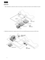
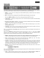
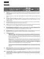
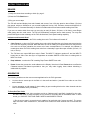
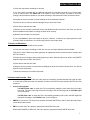
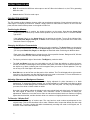
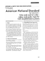
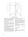
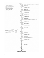
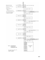
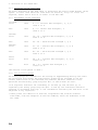
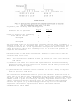
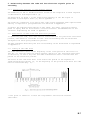
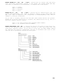
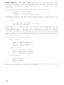
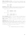
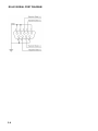
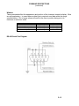
Model F30 Time Code Generator/Reader/Character Inserter User's Guide Fast Forward Video, Inc. 1151 Duryea Ave. Irvine, California, U. S. A. 92614 (949) 852-8404 Copyright 1990-2006, Fast Forward Video The design of the F30 is proprietary. No part of the F30 manual may be copied without the prior written consent of Fast Forward Video TABLE OF CONTENTS Features ................................................................................. 1 Hook Up .................................................................................. 2 Controls Front Panel ................................................................... 3 Rear Panel ................................................................. 4/5 Instructions for Use Reader ......................................................................... 6 Generator .................................................................... 6 To Post-dub time code .......................................... 6 To Prepare an edit master .................................... 7 Character Inserter ....................................................... 8 To Record a "Window Dub" ................................ 8/9 Preset ....................................................................... 9/10 Jam Sync .................................................................... 10 To Replace Sections of Time Code ..................... 10 Inter-format conversion ..................................... 10/11 Regenerate .............................................................. 11/12 MIDI Time Code .......................................................... 12 RS-422 Serial Control ................................................. 12 GPI Output .................................................................. 12 Related Information Facts You Should Know .............................................. 13 Trouble Shooting Time Code Systems .................... 14/15 Technical Specifications .............................................. 16 Limited Warranty ......................................................... 17 Appendices: A: ANSI/SMPTE 12M-1986 B: Excerpt - EBU Time and Control Codes for Television Tape Recordings. 3rd Edition, April 1982 C: F30 RS-422 Serial Protocol/Command Summary D: MIDI Time Code Specifications FEATURES FEATURES SMPTE Longitudinal Time Code Read forward and reverse, 1/30 to over 10x play speed Generate (with pause) Jam Sync Regen Preset hours, minutes, seconds Drop and Non-drop frame Encodes color frame sequence Balanced XLR and unbalanced RCA connectors Window Dub Display on/off, background on/off Variable sizes Window dub user bits Combined display: user bits and time code simultaneously BNC connectors MIDI Time Code Converts SMPTE time code to MIDI Standard 5-pin DIN output EBU (European Broadcast Union) 25 Frame Time Code Color frames to PAL eight-field sequence Can translate between SMPTE/EBU GPI Output (General Purpose Interface) F30 can issue a GPI "command" at specified address RCA connector RS 422 Serial Control Control F30 from computer or edit controller. 9 pin D-subminiature connector 24 Frame rate Time code for film work Synced to line User Bits Preset from front panel Hexadecimal 8 digit or ISO 4 character 1 HOOK-UP HOOK-UP 1. Basic installation to record time code on a source tape, to read time code and to record "window dub” copies. 2. Additional connections for computer control of F30, control of MIDI sequencer and control of GPI device. 2 CONTROLS FRONT PANEL The following indicators and controls always behave as described here. For explanations of the other indicators and controls, see the Reader, Generator, Preset, and Character Inserter sections of this guide. SMPTE - on when the F30 is working with 30-frame SMPTE (Society of Motion Picture and Television Engineers) time code. EBU - on when the F30 is working with 25-frame EBU (European Broadcast Union) time code. When both SMPTE and EBU are off, the F30 is working with 24-frame SMPTE time code. On/Off switch - we hope you can figure this one out. The F30 will retain its presets and mode settings when the power is off. Read, Gen, Preset, Regen, Jam Sync - these buttons activate the indicated function. See the appropriate heading under Instructions for Use for a full explanation. MIDI TC - switches the MIDI time code output on and off. When the indicator lamp is on, the F30 is generating MIDI time code. Arrow Keys - When Preset is off and the indicator light is off these buttons control the position of the time code "window" (the video character inserter's display) on the screen. When you press Preset, the Arrow Keys select and set the time code and user bit digits. See Instructions for Use under Preset. When you press Window, the indicator light at the center of the Arrow Keys comes on. Now Up and Right change the size of the character display (or "window"). Left and Down turn parts of the window off and on (hours, minutes, seconds, and frames). See Instructions for Use under Character Inserter. Display - shows either time code or user bits. Time code is displayed as hours, minutes, seconds, and frames. The frames digits will turn off when the F30 is reading time code over five times play speed. Drop - the indicator light is on when the F30 is working with Drop Frame SMPTE time code. The button functions only when Preset is on. See Instructions for Use under Preset. User Bits - switches the F30's front panel Display between time code and user bits. When the User Bits Indicator is on, the Display shows the numeric user bits that the F30 is generating or reading. If the F30 is generating or reading user bits conforming to the ISO eight-bit character set, the Display will be blank, and the user bits will be visible only on the video character display. See Instructions for Use under Preset. Window - this button changes the character display on the video screen. Each press moves to the next of three possible choices: 1) characters on, background on; 2) characters on, background off; 3) window off Once you have pressed Window, the arrow keys change other aspects of the character display. See Instructions for Use under Character Inserter. Pause - In Gen, this button pauses the F30's time code output. When in Read, Jam Sync, or Regen, this button freezes the F30's front panel Display, but the window and time code output continue. 3 CONTROLS REAR PANEL (1) Video Out - when the F30 is on, the character inserter's time code display is superimposed on the input video signal. See Front Panel - Display/ Preset Controls for details on setting the display's size, position, and composition. When the F30 is off, the input video signal bypasses the Impedance Switch and loops through to this output. (2) Character Contrast / Background Contrast - these dials adjust the brightness of the F30's video character display. See Adjusting Character and Background Contrast under Instructions For Use Character Inserter. (3) Impedance Switch - sets the F30's video input to high impedance (>10K ohms) or 75 ohm termination. The switch only takes effect when the F30's power switch is ON. (4) Video In - the F30 uses this input for two purposes: 1) as a sync reference for generated time code and 2) as the signal on which the character inserter superimposes its time code display. (5) GPI (General Purpose Interface) Out - acts as a “contact closure" when the F30 reaches a specified time code address. You can trigger a character generator, switcher, or any device activated by a GPI input. Use the RS422 Port to specify the time code address for the GPI output. (6) RS-422 Serial Port - an input / output port that allows a computer or edit controller to communicate with and control the F30. See Appendix C: F30 RS-422 Serial Protocol / Command Summary. (7) Field Reference Input: SMPTE time code - The F30 will generate time code identifying the NTSC four-field sequence when a color frame reference signal is present at this connector and you have Preset the F30 to perform color framing. The color frame reference signal should be a TTL level square wave that is high for Frame A and low for Frame B. This signal is provided on most sync generators and one-inch video tape recorders. EBU time code - the F30 will generate time code identifying the PAL eight field sequence when a field reference signal is present at this connector and you have Preset the F30 to perform color framing. The field reference signal should be TTL level and either 1) a low pulse at the beginning of field 1, or 2) a square wave that is low for fields 1 - 4 and high for fields 5 - 8. This signal is provided on most sync generators and one-inch video tape recorders. NOTE: if the F30 is not set to perform color framing through Preset, or if the field reference signal is not present, the F30 will automatically generate EBU time code in sync with the PAL four field sequence. (8) MIDI Time Code Out - the F30 outputs the MIDI (Musical instrument Digital Interface) equivalent of the current SMPTE time code address when the Gen, Jam Sync, or Regen indicator is on. Press the MIDI TC button on the front panel to turn this output on and off. (9/11) Time Code In/Out - connect to the appropriate connectors on your recorder. You may use both outputs simultaneously, but connect to only ONE of the two time code inputs. The RCA type connectors (9) are for high impedance, unbalanced signals and the XLR type connectors (11) are for low impedance, balanced signals. 4 CONTROLS (10) Time Code Output Level - the F30's time code output level is adjusted to maximum amplitude when it leaves the factory. If you find this level too high for your equipment, use a small screwdriver to adjust it. Turn counter-clockwise to lower the output level. Always TEST a new output level: record a few minutes of time code, then play the tape back and verify that the F30, as well as any other time code devices you have, can read this code. 5 INSTRUCTIONS FOR USE READER 1) Verify the connections according to Hook Up, page 3. 2) Press the F30's Read button. 3) Play your source tape. The F30 will read and display time code forward and reverse, from 1/30 play speed to about fifteen (15) times play speed, subject to limitations in your recorder's playback circuitry. See Character Inserter and Appendix C: RS-422 Protocol / Command Summary for further information about these features while reading time code. If you are not certain which frame rate you are trying to read (30 frame, 25 frame, or 24 frame), press Regen while playing the time code source. The F30 will automatically configure itself to read correctly. You may then press Read again to take advantage of the F30's bi-directional, multi speed-reading capability. Indicators and Controls Read Video Lock is inactive when the F30 is reading time code. The indicator will remain off. Color Frame is on when the F30 is reading time code, which identified the color frame sequence when the time code was originally recorded. Note that when the F30 is reading, this indicator does not verify that the time code on the tape maintains the correct color frame correspondence. For example, this indicator is meaningless when the F30 is reading time code from a heterodyne type video tape recorder (3/4 inch, 1/2 inch, or 8 mm). The F30 does not output MIDI time code in Read. The MIDI TC indicator remains off, and the MIDI TC button has no effect. Use Jam Sync or Regenerate to translate SMPTE or EBU from an existing track to MIDI Time Code. Drop Indicator - on when the F30 is reading Drop-Frame SMPTE time code. Pause freezes the current time code address on the Display. Note that in Read, Pause does not affect the Character Inserter. This feature is provided so that you may make logging notes without disturbing a window dub in progress. GENERATOR The following situations are the most common applications for the F30's generator: You have shot a source tape in the field or in the studio and wish to “post-dub" time code on one of the audio channels. You are preparing an edit master for insert editing by pre-recording black on the video channel and time code on the address track (if available). To Post-Dub Time Code: Note: Many professional video recorders provide an "address track" specifically intended for time code. Be aware that most of these recorders do not provide for an audio dub on the address track. In other words, you CAN NOT POST-DUB TIME CODE ON AN ADDRESS TRACK. 1) Put the source tape in a recorder that is capable of an audio dub (the "source recorder"). The source tape must have video recorded on it, and must have at least one audio channel free to record the time code. 6 INSTRUCTIONS FOR USE 2) Verify the connections according to Hook Up. 3) You may record a window dub on a different tape while you post dub time code on your source tape. To do so, connect the F30's Video Out to the Video In of the "dub recorder" as shown in Hook Up. Configure and position the window to your taste according to the instructions under Character Inserter. 4) Prepare the source recorder for audio dubbing on the unused audio channel. 5) Preset the hours, minutes, and seconds digits as you wish. See Preset. 6) Press Gen to start the time code. 7) Start the source recorder in audio dub mode, and adjust the audio record level. See Facts You Should Know for additional information on setting the audio level correctly. 8) Start the dub recorder in record mode. 9) You may Pause the time code output at any time. However, to achieve an uninterrupted time code recording, allow all machines to run continuously until the source tape ends. To Prepare an Edit Master: 1) Insert a blank tape into the source recorder. 2) Verify the connections according to Hook Up. Use your recorder's address track if available. 3) Be sure to route a black burst video signal from an appropriate source to both the source recorder and the F30's Video In. 4) Preset the hours, minutes, and seconds digits as you wish. Select the format you wish to use (SMPTE drop/non-drop frame or EBU). See Preset. 5) Press Gen to start the time code. 6) Start the source recorder in record mode, and adjust the audio record level. Review Facts You Should Know for further information. 7) Allow the recorder to run until the tape ends. Indicators and Controls – Gen Video Lock is on when the F30's time code output is successfully synchronized with the signal at Video In. In the case of EBU time code, the indicator is lit when the F30 is correctly locked to the PAL four-field sequence. Color Frame indicator: For SMPTE time code: on when the F30 is successfully setting the color frame flag in its output time code. The color frame flag will be set according to the four-field signal at the Field Ref input on the rear panel. For EBU time code: on when the F30 is successfully generating time code in the EBU eight-field sequence according to the Field Ref input on the rear panel. SMPTE is on when the F30 is preset to generate 30 frame SMPTE time code in either the Drop Frame or Non-Drop Frame format. EBU is on when the F30 is preset to generate 25 frame EBU time code. When neither SMPTE nor EBU is lit, the F30 is preset to generate 24 frame SMPTE time code. 7 INSTRUCTIONS FOR USE MIDI TC switches the MIDI time code output on and off. When the indicator is on, the F30 is generating MIDI time code. Pause halts the F30's time code output. CHARACTER INSERTER The F30 contains a video character inserter, which can superimpose a display of time code and user bits on a video signal. This display is known as a "window." Simply connect a video source to Video In on the F30's rear panel, and the window will be present on the signal at Video Out. Positioning the Window Use the Arrow Keys to position the window anywhere on the screen. Note that the Arrow Keys perform several functions; they control window position only when Preset is NOT LIT and the indicator light is OFF. If the indicator light is on, the Arrow Keys will not position the window. To turn off the indicator light, press Read, Gen, Regen, Jam Sync, or Preset. If one of these keys is lit, press that one in order not to disturb the function in progress. Changing the Window Characteristics Press the Window button to set the window's size and composition. The Arrow Keys now change the appearance of the window. To restore the Arrow Keys to their default function of moving the window, you must press Read, Gen, Regen, or Jam Sync as described under Positioning the Window above. Each press of the Window button selects the next of three possible formats: Background Off, Window Off, and the default format, characters with background. The Up key varies the height of the window. The Right key varies the width. The Left and Down keys turn time code digits on and off. Press the Left key to select the hours, minutes, seconds, or frames digits, which will flash. One press of the down key will cause that portion of the window to go black, indicating that it will not appear when you return to normal operation. You may turn off any or all of the digits in this manner. User Bits turns on and off the user bits portion of the window. The F30 will display either eight numeric user bits or four character user bits directly below the time code on the screen. For more information on numeric and character user bits, see User Bits under Preset. Adjusting Character and Background Contrast The F30 leaves the factory with its character display adjusted for white characters on a black background. To change the display contrast, use a small screwdriver (a flat blade works best) to adjust the Character Contrast/ Background Contrast dials on the F30's rear panel. You may vary the display to your taste, from white on black to black on white. Note that it is possible to adjust the display levels past nominal black and white levels, and thus distort the video signal at Video Out. If possible, use a waveform monitor or oscilloscope to make your adjustments. Otherwise, route color bars to Video In and set the window's black to a maximum of slightly lighter than the black bar, and the window's white to a maximum of slightly darker than the white bar. To Record a “Window Dub" A "Window Dub” is a copy of another tape. The copy has time code numbers superimposed on the original image. This section describes how to make a window dub of a tape that already has time code recorded on it. To make a window dub while simultaneously recording time code on the original, see To Post-Dub Time Code under Generator. 8 INSTRUCTIONS FOR USE 1) Verify the connections according to Hook Up. 2) Put the source tape in the “source player". 3) Connect the F30's Video Out to the Video In of the dub recorder as shown in Hook Up. Configure and position the window to your taste according to the instructions above. 4) Press Read. 5) Start the source player in play mode. 6) Start the dub recorder in record mode. PRESET Preset configures the F30's generator. The settings take effect in Gen, Jam Sync, and Regen. Use Preset and the Arrow Keys to set a starting time code address and user bits. Use Preset and the Drop button to select the time code format (SMPTE drop frame, non-drop frame, 24 frame, or EBU), and to activate or disable color framing. See the explanation under Indicators and Controls below. You can set the hours, minutes, and seconds to any time code address from 00:00:00:00 to 23:59:59:00. The range of possible starting time code addresses is limited by SMPTE and EBU specifications. For example, you could not set the F30 to 62 minutes or 78 seconds. One common application of this feature is to set the hours digits to a different number for each tape in a program with multiple source tapes. Indicators and Controls = Preset To preset the F30, start by pressing Preset. The indicator will light up, and the indicators and controls will behave as described here. Video Lock is inactive. The indicator is off. Color Frame indicator comes on when you activate color framing by pressing Drop. See the explanation below. SMPTE is on when you select 30 frame SMPTE time code in either the Drop Frame or Non-Drop Frame format. Choose the format by pressing Drop. EBU is on when you select 25 frame EBU time code by pressing Drop. When neither SMPTE nor EBU is lit, you have selected 24 frame SMPTE time code. Arrow Keys - The Left and Right buttons select a digit, which will flash both on the front panel display and on the character inserter's video display. The Up and Down buttons change the digit's value up or down. Holding a button down has the same effect as repeated pressing. The Display shows either time code or user bits. If the display is blank and User Bits is on, the F30 is set to generate character user bits. See User Bits below. Drop - Use this button to select the time code format. Each successive press of the Drop button selects the next possible format, with or without color framing when appropriate. 1) 30 frame SMPTE non-drop 2) 30 frame SMPTE non-drop with color framing 3) 30 frame SMPTE drop frame 4) 30 frame SMPTE drop frame with color framing 5) 25 frame EBU 6) 25 frame EBU with 8-field color framing 7) 24 frame SMPTE 9 INSTRUCTIONS FOR USE Observe the Display, the Drop indicator, and the Color Frame indicator until you arrive at the combination you desire. User Bits switches the F30's displays between time code and user bits. To select user bits conforming to the ISO eight-bit character set, press and hold both the left and right arrow keys simultaneously. The front panel display is blank when character user bits are selected; in this case, observe the video character inserter's user bits display on a monitor while using the Arrow Keys to set the user bits. Note that the F30 will generate the same user bits until you explicitly change them through Preset. These user bits will appear in time code generated in Gen and Jam Sync. Pause will put the F30 in a standby state when you switch from Preset to Gen. JAM SYNC In Jam Sync the F30 matches its output to incoming time code. The F30 generates as usual, and continuously monitors the Time Code In connector. When incoming time code starts or changes, the F30 synchronizes with it. When incoming time code stops, the F30 continues generating. The F30 can transfer time information from one time code format to another through jam sync. See Inter-format Conversion on next page for a full discussion. The most common use for jam sync is to continue time code where it stops on a previous recording. Common situations are: You are shooting a source tape in the studio and wish to record time code as you go, making sure that the count remains continuous even when the recorders are stopped between takes. You wish to replace a section of time code that is missing, perhaps accidentally erased. To Replace Sections of Time Code: 1) Verify the connections according to Hook Up. Note that both the F30's Time Code In and Time Code Out must be connected to the source recorder's appropriate Audio Out and Audio In. 2) Prepare the source recorder for an audio insert edit on the appropriate audio channel. 3) Confirm that the F30 is set to generate time code in the same format as the source time code. See Preset. 4) Press Jam Sync. 5) Select your edit-in point at least one second before the problem section. 6) Preview the edit at least once to verify proper connections and levels. 7) Perform the edit. Inter-format Conversion The F30 will generate time code in the format you have selected through Preset, regardless of the incoming time code's format. This feature is provided to convert time code from one format to another. It is possible to change user bits, to align non-color framed time code with the color frame sequence, or to convert between formats with different frame rates. During a conversion between formats with different frame rates (for example, 30 frame SMPTE Drop-frame and 25 frame EBU), the generated time code will not maintain a one to one correspondence with incoming time code, but hours, minutes, and seconds will correspond to within two frames. 10 INSTRUCTIONS FOR USE Note that the F30's indicators and controls behave exactly as they do when the F30 is set to Gen. The displays and indicators describe the time code being generated, NOT the input time code. 1) Connect the time code source to the F30's Time Code In. 2) Connect the F30's Time Code Out to the dub recorder's Time Code In or Audio In, as appropriate. 3) Route the source video through the necessary standard converter to the dub recorder's Video In. 4) Connect the dub recorder's Video Out to the F30's Video In. This will synchronize the F30's generator with the video on the copy. 5) Select the format you desire, starting address and user bits through Preset. 6) Press Jam Sync. 7) Record the copy. REGENERATE Regeneration restores the time code signal to the proper shape and properly synchronizes the time code output to reference video. The F30's output time code is the same as the input time code: the F30 automatically chooses the correct format (for example, drop or non-drop frame SMPTE), user bits are unchanged, and discontinuities in the input are duplicated. Regeneration is necessary because an audio channel's playback head is slightly offset from its record head, which results in a phase shift of as much as half a field of video. This phase shift would compound if you were simply to re-record the time code. NOTE: Regeneration is NOT NECESSARY if you are using an address track. Address tracks are designed for the demands of time code recording and playback, and thus do not distort the time code signal's shape or cause a phase shift. The Regenerate function is primarily useful when you wish to duplicate a tape that has time code recorded on an audio channel. 1) Verify the connections according to Hook Up. If you do not wish to record visible time code on the copy (a "window dub"), be sure to turn off the F30's window. See Character Inserter instructions. 2) Press Regen. 3) Play the source tape on the "source recorder" and record the duplicate on the “dub recorder". 4) See Facts You Should Know for additional information on setting the audio level correctly. In Regen, the F30 automatically determines the format of the input time code. Thus, this function is useful to see what kind of time code is on a tape. Further, a few seconds in Regen will automatically configure the F30 to generate, read, or jam sync time code in the same format. Indicators and Controls - Regen Except as noted below, all indicators and controls behave as described in Generator under Indicators and Controls - Gen. Video Lock is on when the F30's time code output is successfully synchronized with the signal at Video In. If the F30 is connected according to Hook Up, Video Lock indicates that output time code is correctly re-locked to the source tape's video. 11 INSTRUCTIONS FOR USE Color Frame on shows that the time code at Time Code In contains color frame information. This does not guarantee that the time code is aligned with the color frame sequence: the source time code may have been inaccurately recorded with respect to the color frame sequence, or the source video may not reproduce the color frame sequence at all (as in the case of 3/4 inch or 1/2 inch players). Pause freezes the current time code address on the front panel Display. In Regen, Pause does not affect the time code at Time Code Out or the Character Inserter. This feature is provided so that you may make logging notes without disturbing a duplication in progress. MIDI TIME CODE MIDI stands for Musical Instrument Digital Interface. MIDI is a standardized protocol for communication among electronic musical instruments and their controllers. The F30 can send time code directly to MIDI instruments, such as sequencers or computer-based cue-list programs, via MIDI Time Code. The F30 can convert SMPTE or EBU time code into MIDI protocol. Simply press the MIDI TC button. While generating SMPTE or EBU time code, the F30 will continuously output the equivalent MIDI time code at the rear panel MIDI Out connector. The F30 outputs MIDI Time Code when it is set to Gen, Regen, or Jam Sync. Regen is the best choice to convert an existing time code track to MIDI time code. For a thorough technical discussion of MIDI, see Appendix D, MID/ Specification. RS-422 SERIAL CONTROL The F30 will operate under the control of a computer or edit controller through the RS-422 Port located on the rear panel. RS-422 serial commands will activate all of the F30's functions including address and user bit preset, control of the window (the F30's video character inserter display), start, and pause. A computer can receive time code information either continuously or on request. For complete details see Appendix C, F30 RS-422 Serial Protocol Command Summary. Devices which convert from computer industry standard RS-232 to video industry standard RS-422 are available from various vendors. Fast Forward does not provide these devices directly, but can provide a few sources on request. GPI OUTPUT The F30 provides a GPI (General Purpose interface) output on its rear panel. A GPI "trigger" is a common means of activating various video production devices, from character generators to switchers and special effects generators. By sending out a GPI trigger at a designated time code address, the F30 can precisely control the timing of an effect or edit. To set the time code address for the GPI output, you must use the RS-422 Port. See Appendix C/ F30 RS-422 Serial Protocol/Command Summary for information on setting up a GPI trigger. 12 RELATED INFORMATION FACTS YOU SHOULD KNOW Time Code is an audio signal. It must be recorded and played from an audio channel. An address track is an audio channel designed for time code. Time Code is synchronized with the video signal, and the audio time code information corresponding to each frame number is exactly as long as one frame. If you intend to use the F30's time code output on a video recording, you must connect that video signal to the F30's Video In connector when generating to insure generated time code is correctly synchronized with video. If you are using the F30's Time Code output on an audio recording, you do not need to route any signal to the F30's Video in connector. Time Code is a high level audio signal, and it may bleed over onto adjacent sound tracks if recorded at too high a level. The goal is to record the Time Code at as high a level as possible without interfering with the other channels. Experiment until you arrive at a level that works consistently with your recorders, then stick with it. If your recorder has an address track, use it. Otherwise, use the audio track closest to the edge of the tape (channel 1 on 3/4 inch VCRs). Avoid using an automatic recording level. The address track is a specialized audio channel designed to record and reproduce SMPTE time code. Not all VTRs are equipped with address tracks. Aside from the obvious benefit of freeing up both audio channels for production sound, the address track does a much better job than an audio channel of playing back Time Code at all search speeds. The address track has one serious limitation: you can record Time Code on it only when you are recording video at the same time. Thus, you cannot post-dub time code onto an address track. 13 RELATED INFORMATION TROUBLE SHOOTING TIME CODE SYSTEMS To isolate problems, isolate equipment. If operation of the F30 is in question, remove the unit from your system and test it individually. 1) Unplug all inputs and outputs from the unit. 2) Connect the power plug. If possible, use a different circuit than the one on which you observed problems. 3) Generate time code and record it on an audio cassette deck and set the recording level to least 0 dB. Use different patch cords than those you were using when you noticed the problem, and do not route through a patch bay or a distribution amplifier. 4) Play back the tape. Attempt to read, regenerate, and jam sync to the time code on the tape. 5) Run video from house black or a color bar generator to the unit. Again, use fresh cables, and avoid patch bays and distribution amplifiers. 6) Run video from the F30 to a monitor. 7) Test the F30's ability to do window dubs. If your F30 does not pass these tests please contact your dealer, factory authorized representative, or the factory directly. Please be prepared with your unit's serial number, the dealer you purchased the unit from, and the approximate purchase date. Your satisfaction is our number one priority. If this simple procedure convinces you that your unit is properly generating and reading time code, and can insert a window dub on a known good video source, then refer to the following list of problems and solutions. 14 RELATED INFORMATION PROBLEM SOLUTIONS Time Code loses time. Gen-lock input video and time code generator to a known good external source. Video level too low, looks bad. Change impedance switch position. Can't move window, or window jumps Only push one of the arrow keys at a time. Press firmly. Time code is erratic or numbers freeze when reading. Gen-lock video and the F30 to an external, known good video source such as a color bar generator. Difficulty reading time code Problems reading time code are generally caused by poor recording. NOTES If this solves your problem it indicates bad sync information on the tape. Irregular incoming sync, or previously recorded Vertical Interval Time code disrupts time code generation erratically. 1) Turn off noise reduction on audio channel that time code is being recorded on. Don't use automatic level adjustment. Time code is not normal audio program material, although it is recorded on an audio channel. 2) Adjust output level of time code when recording. Use appropriate tools to adjust output level control on rear panel. No window dub when the window is turned on. Try moving the window with the arrow keys. Sometimes the window will be hidden in the over scan portion of the video. Window dub causes flagging. Adjust character and / or background contrast to shades of gray instead of dark black and bright white. Extreme white or black will sometimes exceed the limits of a normal video signal. 15 RELATED INFORMATION TECHNICAL SPECIFICATIONS Video Input: 1.0 Vp-p. 75 ohm or high impedance. BNC. Video Output: Characters are keyed onto the input signal. Unity gain amplification. When the F30's power switch is off, the input signal loops through and bypasses termination. BNC. Time Code Out: Adjustable from 0 to 4 V p-p into high impedance. When the F30's power switch is off, the input signal loops through either input to unbalanced output. Unbalanced, RCA. Balanced, XLR. Time Code In: High impedance, unbalanced, RCA phono connector. Signal range from 500 mv to 8 V p-p. 600 ohm, balanced, XLR. GPI Out: Open collector active low output. F30 can be set through RS422 port to issue a GPI trigger when any given time code address is read, generated, or regenerated. RS-422: Industry standard communications protocol. D-subminiature 9 pin connector. ALL time code functions of F30 can be controlled. Also, continuous time code output possible. See Appendix C: F30 RS-422 Serial Protocol appendix for command descriptions. Field Ref. Input: 5.0 V p-p. BNC. MIDI Time Code Out: Industry standard. 5 pin, 180 degree, circular DIN. Window Display: 16 character sizes. Contrast adjusts for white characters on black background to black characters on white background. Position fully adjustable from front panel. Can display any combination of User Bits, and time code Hours, Minutes, Seconds, and Frames. Front panel on/off. Power Requirements: 110-120 Volts AC, 50-60 hz, or 220-240 AC, 5060 hz. Configured at factory, specify when ordering. Dimensions: 1 9"W x 61/4"L X1 3/4"H. Standard single unit rack size. 16 RELATED INFORMATION LIMITED WARRANTY 12 – MONTH LIMITED WARRANTY Fast Forward Video, Inc. warrants to the original purchaser that the product (Hardware and components) shall be free from defects in material and workmanship for a period of 1 year from the date of purchase, If a defect covered by this warranty occurs during this 1 year period, Fast Forward Video, Inc. will repair or replace the defective product or component, at its option, free of charge. WARRANTY LIMITATIONS THIS WARRANTY SHALL NOT APPLY IF THIS PRODUCT: (a) IS DAMAGED BY NEGLIGENCE, ACCIDENT, MISUSE, OR BY OTHER CAUSES UNRELATED TO DEFECTIVE MATERIALS OR WORKMANSHIP; OR (b) HAS HAD THE SERIAL NUMBER ALTERED, DEFACED, OR REMOVED. ANY APPLICABLE IMPLIED WARRANTIES ARE HEREBY LIMITED IN DURATION TO THE WARRANTY PERIOD DESCRIBED ABOVE. IN NO EVENT SHALL FAST FORWARD VIDEO, INC. BE LIABLE FOR CONSEQUENTIAL OR INCIDENTAL DAMAGES RESULTING FROM THE BREACH OF ANY IMPLIED OR EXPRESS WARRANTIES. SOME STATES DO NOT ALLOW LIMITATIONS ON HOW LONG AN IMPLIED WARRANTY LASTS OR EXCLUSION OF CONSEQUENTIAL OR INCIDENTAL DAMAGES, SO THE ABOVE LIMITATIONS MAY NOT APPLY TO YOU. This warranty gives you specific legal rights and you may also have other rights which vary from state to state. 17 APPENDICES A-1 A-2 A-3 A-4 B-1 3. Code Format 3.1. Rate of change of the code word Each television picture, comprising an odd-numbered field followed by an even-numbered field*. shall be identified by a complete code word. 3.2. Composition of the code word Each code word shall consist of 80 bits, numbered from 0 to 79 inclusive. 3.3. bit assignment The bits shall be assigned as shown in Fig. 2 and as described below: 0 - 3 4 - 7 8 - 9 10 11 12 - 15 16 - 19 20 - 23 24 - 26 27 28 - 31 32 - 35 36 - 39 40 - 42 43 44 - 47 48 - 51 52 - 55 56 - 57 58 59 60 - 63 64 - 79 Units of pictures First binary group Tens of pictures Unassigned bit (see 5 4.6) Colour lock flag bit (see 5 4.4) Second binary group Units of seconds Third binary group Tens of seconds Binary group flag bit (see 5 4.3) Fourth binary group Units of minutes Fifth binary group Tens of minutes Binary group flag bit (see 5 4.3) Sixth binary group Units of hours Seventh binary group Tens of hours Unassigned bit (see 5 4.6) Bi-phase mark phase correction bit (see 5 4.5) Eighth binary group Synchronizing word: 64 - 65: fixed zero 66 - 77: fixed one 78 : fixed zero 79 : fixed one * Odd-numbered fields : fields 1, 3, 5, 7 } defined in CCIR Report 624-2 [3] Even-numbered fields: fields 2, 4, 6, 8 } defined in CCIR Report 624-2 [3] B-2 B-3 4. Structure of the coded data 4.1.* Structure of the time Label The basic structure of the time label is based upon the binary Coded Decimal (SC'D) system. In those cases where the count does not attain 9, only 2 or 3 bits are required, rather than 4 bits as is normal in the BCD code. 4.2.* Assignment of the time bits Pictures Units Bits 0 - 3 : four-bit BCD arranged 1, 2, 4, 8 count 0 to 9. Tens Bits 8 - 9 : two-bit BCD arranged 1, 2 count 0 to 2. Seconds Units Bits 16 - 19 : four-bit BCD arranged 1, 2, 4, 8 count 0 to 9. Tens Bits 24 - 26 : three-bit BCD arranged 1, 2, 4 Minutes Units Bits 32 - 35 : four-bic BCD arranged 1, 2, 4, 8 count 0 to 9. Tens Bits 40 - 42 : thr-e-bit BCD arranged 1, 2, 4 count 0 to 5. Hours Units Bits 48 - 51 : four-bit BCD arranged 1, 2, 4, 8 count 0 to 9. Tens Bits 56 - 57 : two-bit BCD arranged 1, 2 count 0 to 2. (The 24-hour clock system is used.) 4.3.* Use of binary groups The binary groups are intended for the storage of supplementary data by the users. The thirty-two bits within the eight binary groups may be assigned in any way without restrictions if the character set used for the data insertion is not specified and the binary group flag bits Nos. 27 and 43 both are zero. If an eight-bit character set conforming to I50 646 [4] and ISO 2022 [5] is signaled by the binary group flag bits Nos. 27 and 43, the characters should be inserted in accordance with Fig. 3. The information carried by the user bits is not subjected to any regulation. * These points are identical in both the longitudinal and vertical-interval time-codes, with the exception of the bits numbers, which are different in the two codes. B-4 At present, the following truth-table applies: Bit 27 0 Bit 63 0 1 0 Unassigned 0 1 Unassigned 1 1 Character set not specified Eight-bit character set conforming to IS0 646 and IS0 2022 The unassigned states of the truth-table cannot be used and their assignment is reserved to the EBU. If it becomes clear that no use is to be expected for them, it is possible that bit No. 43 can again become unassigned and thus available for other applications, while still retaining bit No 27 to signal the presence of eight-bit ISO characters. It should be noted that, in each time code word, some user bits will be decoded before bits Nos. 27 and b3 are encountered. The data in these earlier user-bit locations must not be lost. Note. - The International Standard ISO 646 [4] defines two 7-bit Latin character code tables: a) The basic code cable with control and alpha-numerical characters including punctuation marks can free positions for national use and some positions with more than one graphic symbol; b) The international reference version (referred to as IRV), where the national positions are filled and a choice is made where more than one graphic symbol is shown in the basic code table. The International Standard ISO 2022 t51 gives code extension techniques from the 7-bit code of ISO 646 to 8-bit codes, based on the use of the "escape' command of the basic code table of ISO 646. With character-combinations following the “escape” command access is given to a library of centrally registered character sets. This library consists of national character sets like the American ASCII although versions for special (e.g. broadcast) applications may also be included and registered. This central registration is done by the French national standardization office AFNOR. B-5 6.4.* Colour-Lock flag bit The colour-lock flag bit No. 11 shall be set to "1" when the time-code is locked to the associated PAL colour signal in accordance with the eight-field sequence, and when the video signal has the "preferred sub carrier-to-line-sync phase" (see § 5.1). 4.5. Bi-phase mark phase-correction bit The purpose of the phase-correction bit it to compensate for phase reversals in the bi-phase mark modulation that could occur when code inserts are performed. Such compensation may be required when code inserts modify the content of any of bits 0 to 63, bit 59 excluded. In order that the magnetization transient between bit-cell 79 of one word and bit-cell 0 of the next shall always be in the same direction, bit 59 will be put in a state where every 80-bit word will contain an even number of logic zeros. This requirement results in the following truth table for bit 59: Number of logic zeros in bits 0 to 63 (59 exclusive): Odd Even Bit 59 1 0 In drawing up this specification, the use of time-code write/read systems that have equal polarity relations between input/output voltage and the tape magnetization is assumed. This specification should not be understood as a requirement for time-code insert capability in television tape-machines in situations where tapes have to be interchanged, until further notice from the EBU. 4. 6.* Unassigned bits Bits 10 and 58 are reserved for future assignment and shall be zeros until specified by the EBU. * These points are identical in both the longitudinal and vertical-interval time-codes, with the exception of the bits numbers which are different in the two codes. B-6 5. Relationship between the code and the television signals prior to recording 5.l.* Definitions relevant to the present section The numbering of PAL or SECAM television fields in the respective 4-field sequence is described in CCIR Report 624-2 [3]. The definition of field 1 in the eight-field sequence of the PAL signal is described in CCIR Report 624-2 [3] and in Appendix 1. The stability conditions to be met by PAL video source equipment when sophisticated editing is required in post-production are detailed in Appendix 2. To permit the sophisticated editing of PAL tapes, the video line-sync-to-burst phase on replay must be held within a certain tolerance. Recommendations on the tolerance required may be found in Appendix 3. 5.2. Association of code words and television pictures In generating the code, each code word is associated with one particular television picture, with which it coincides in time. This relationship must be maintained throughout the whole post-production process. The EBU Statement describing how this relationship can be maintained is reproduced in Appendix 4. 5.3. Timing of the code word The code word shall start at the beginning of the clock period of the first bit (bit No. O). The bits shall be evenly spaced, subject to the tolerances specified in Section 6, in such a way that the code word duration shall coincide with the period of one television picture. The start of the code word shall occur within the period of the sequence of field-synchronizing pulses [3], at the beginning of the picture with which the code word is associated (Fig. 4). * This point is identical in both the longitudinal and vertical-interval time-codes. B-7 5.4. * Relationship between the time address and the associated colour television signal During electronic editing of colour signals recorded on television tape machines, it is important that: a) in the case of editing in SECAM or simple editing in PAL, the correct four-field sequence be maintained in the edited master**; b) in the case of sophisticated editing operations on PAL signals, the correct eight-field sequence also be maintained in the edited master, and that the "in-phase" or "out-of-phase" position of a slave tape** can be controlled. Condition b) does not apply to SECAM signals. These sequences can be preserved with the aid of the time-and-control code, provided that there exists a fixed relationship between the time addresses of the code and the sequence of television fields. Therefore, it has been agreed that, when necessary, the on-tape relationship between the time address-numbers of the EBU time-and-control code and the associated eight fields of the PAL video signal, shall be as follows: If bit No. 0 is A, bit No. 8 is D, bit No. 16 is B, bit No. 17 is E, bit No. 1 is C, bit No. 24 is F, in order to fulfill condition a) above the code generator shall be locked to the associated video signal in such a way that: a) A where B = "1" for fields 1 and 2 (and fields 5 and 6) constituting odd pictures “0” for fields 3 and 4 (and fields 7 and 8) constituting even pictures, = logical "exclusive or". (For the numbering of fields, see CCIR Report 624-2 [3] and Appendix 1). When it is also desired to fulfill condition b), in addition to condition a), the code generator shall, additionally, be locked to the associated PAL video signal in such a way that: When the time-code is displayed in decimal numbers, S and P designating the numbers of seconds and pictures respectively, condition a) is expressed as: and condition b) is expressed as: b) the remainder on dividing S + P by 4 is 0 for fields 7 and 8 2 for fields 3 and 4 1 for fields I and 2 3 for fields 5 and 6 This point is identical in both the longitudinal and vertical-interval time-codes, with the exception of the bits numbers, which are different in the two codes. **Edited master: the videotape on the recording television tape-machine in an edit installation. Slave tape: the videotape on a play-back television tape-machine in an edit installation. B-8 6. Waveform of the time-and-control code signal Although time code signals serve for the transmission of data, it is more advantageous, in studio practice, if such signals can be handled as ordinary audio signals. The characteristic described hereafter takes into account this prerequisite*, as well as permitting unambiguous data recovery. This waveform is referred to as the "EBU Standardized characteristic of the time-and-control code signal", and the output of time code generators shall conform to it (Fig. 5). Rise and fall time: μs measured between the 10% and 90% amplitude points of the waveform Shape of transition: similar co the edge of a sine squared pulse Maximum overshoot, undershoot, tilt: 5% of peak-to-peak amplitude Clock period: 5oo μs (nominal) Maximum timing error of any clock period: + 2.5 μs Maximum timing error of "one" transition : + 2.5 μs The preferred specifications for the outputs of time code generators are described in the EBU Statement reproduced in Appendix 5. * The signal described here has harmonics at least 40 dB down at 15 kHz. B-9 APPENDIX C ~ F30 RS-422 SERIAL PROTOCOL Firmware Rev. before Version 4.2 – Oct. 1994 PROTOCOL — 9600 Baud, 8 DATA BITS, ODD PARITY, 1 STOP BIT COMMAND FORMAT TO F30 (+ CHECKSUM) F30 RESPONSE FORMAT (+ CHECKSUM) READ GEN REGEN JAM SYNC MIDI ON MIDI OFF MODE CHANGE PAUSE UNPAUSE PRESET CMD1 40H 40H 40h 40H 40H 40H 41H 40H 40h 44H CMD2 80H 81H 82H 83H 84H 90H 85H 0EH 0EH 04H DATA — — — — — — 1 Byte — — 4 Bytes RTN PRESETS/UB 61H OAH 1 Byte SET USER BITS RTN CURRENT TC RTN TC EACH FRAME Bytes/frame STOP TC EACH FRAME WINDOW/BKGND ON/OFF CHANGE CHAR SIZE CHANGE WINDOW POS FORMAT WINDOW RETURN F30 ID COMPARE TC (GPI) COMPARE TC OFF HIGH SPEED MODE ERROR/BAD CMD RETURN MODE/STATUS 44H 61H 60H 05H 0CH 70H 4 Bytes 1 Byte — BYTE1 10H 10H 10H 10H 10H 10H 10H 10H 10H 10H 10H 74H 78H 74H 10H 74H 74H BYTE2 01H 01H 01u 01H 01H 01H 01H 01H 01H 01h (If Valid) 13H (If Invalid) 08H (User Bits) 08H (Time Code & UB) 05H (Time Code) 01H 04H 04H 60H 41u 41H 42H 41H 00H 64H 60H 60H 71H 86H 87H 88H 8AH 11H 71H 77H 72H — 1 1 2 1 — 4 — — — — 10H 10H 10H 10H 10H 12H 74H 10H 10H 11H 72H 01H 01H 01H 01H 01H 11H 84H 01H 80H 12H 80H Byte Byte Bytes Byte Bytes DATA — — — — — — — — — 4 Bytes 8 Bytes 4 Bytes 4 Bytes 4 — 2 Bytes 4 Bytes — — — 2 Bytes CHECKSUM NOTE: A checksum follows each command packet (CMD 1, CMD2, Data). The checksum is the sum of CMD 1, CMD2 and Data, truncated to the low byte. For example, to preset the F30 to 1 hr., 30 min., 30 sec. send: high nibble tens digit low nibble units digit 44H 04H 01 H 30H 30H 01 H AAH Preset command frames (ignored) seconds minutes hours sum of the above values, truncated to low byte. TERMINOLOGY NOTE: Where appropriate the data is referred to in the following manner. When more than one byte of data is returned or sent, byte 1 is always the first byte of data, byte 2 the second, etc. Within a byte the Most Significant Bit, (MSB) is the bit furthest to the left (10000000 B) and the Least Significant Bit, (LSB) is the bit furthers to the right (00000001 B). The MSB is bit 7, and the LSB is bit 0. An X in a binary word indicates that the value of that particular bit does not matter, i.e. “Don't care.” H indicates hexadecimal, B indicates binary and data not otherwise notated is decimal. C-1 COMMAND DESCRIPTIONS CHANGE CHAR SIZE ( 41H 87H 1 Byte ): Command changes the vertical and horizontal sizes of the window dub characters. F30 returns HIGH SPEED MODE, (10H 80H), if currently reading at high speed, ERROR BAD CMD, (11H 12H), if command is not interpreted, or acknowledgement, (10H 01H) if command is correctly interpreted. 1 data byte: Bit 0,1 = Character Height, (00, 01,10,11) Bit 2,3 = Character Width, (00, 01,10,11) All other bits = x (Don't care). CHANGE WINDOW POSITION ( 42H 88H 2 Bytes ): Command changes the location where the upper left corner of the window begins on the screen. F30 returns HIGH SPEED MODE, (10H 80H), if currently reading at high speed, ERROR/BAD CMD, (11H 12H), if command is not interpreted, or acknowledgement, (10H 01H) if command is correctly interpreted. Send 2 data bytes: Byte 1 = Vertical position. Byte 2 = Horizontal position. The screen is divided into a 64 by 64 grid, where 64,64 is the upper left corner, and 0,0 is the lower right corner. Values should be greater then 2, and less then 64 to be considered valid. If values are outside valid range the F30 will return an ERROR/BAD CMD, (11H 12H). COMPARE TC (GPI) ( 64H 71H 4 Bytes ): Sends a complete time code address to the F30 and tells the F30 to toggle the GPI port when that time code address is READ, GENerated, REGENerated, or JAM SYNCed. F30 returns HIGH SPEED MODE, (30H 80H), if currently reading at high speed, ERROR BAD CMD, (11H 12H), if command is not interpreted, or acknowledgement, (10H 01H) if command is correctly interpreted. Send 4 data bytes: Byte 1 = Frames. Byte 2 = Seconds. Byte 3 = Minutes. Byte 4 = Hours. The COMPARE TC (GPI) is frame accurate in the read mode only when the time code is being read at play speed, plus or minus 2 frames per second, or slower. At higher speeds the COMPARE TC (CPI) is accurate only to the nearest second. Use the RETURN CURRENT TC while VTR is shuttling to locate approximate position of event, then slow VTR to play speed and use COMPARE TC (GPI) to improve accuracy. COMPARE TC OFF ( 60H 77H 4 Bytes ): Turns of the COMPARE TC (GPI) mode. F30 returns HIGH SPEED MODE, (10H 80H), if currently reading at high speed, ERROR BAD CMD, (11H 12H), if command is not interpreted, or acknowledgement, (10H 01H) if command is correctly interpreted. Keeps the F30 from issuing spurious GPI toggles. C-2 ERROR/BAD CMD ( - - - ): This command is issued by the F30 when it has received data which it can not parse as an acceptable command. This can occur when the command is wrong, or the accompanying data is improperly formatted or incomplete. Generally receiving this command will indicate that the previous command sent to the F30 should be verified and re-sent. ERROR BAD CMD has precedence over the HIGH SPEED MODE command. The F30 returns l Byte of data indicating probable source of error: Byte 1 04H 40H 10H 20H 02H 22H 01H = = = = = = = Checksum error Parity error 0verrun (Hardware) Framing error 0verrun (Software) Software Unidentified command FORMAT WINDOW ( 41H 8AH 1 Byte ): This command toggles on and off individual sections of the time code being inserted in the window dub. F30 returns HIGH SPEED MODE, (10H 80H), if currently reading at high speed, ERROR BAD CMD, (11H 12H), if command is not interpreted, or acknowledgement, (10H 01H) if command is correctly interpreted. The time code frames, seconds, minutes, and hours can all individually be added or removed from the display. Additionally, the user bits can be added or removed from the display. 1 data byte: Bit 0 = Toggles the Frames on and off, (1 on, 0 off). Bit 1 = Toggles the Seconds on and off, (1 on, 0 off). Bit 2 = Toggles the Minutes on and off, (1 on, 0 off). Bit 3 = Toggles the Hours on and off, (1 on, 0 off). Bit 4,5 = Format User Bits display, (00 = NUB, 01 = CUB, 2&3 = Reserved for future use.) Bit 6 = Toggles the User Bits on and off, (1 on, 0 off). Bit 7 = Toggles the LED between User Bits and Time Code, (1 UB on, 0 UB off). GEN ( 40H 81H —): Switches F30 into generate mode. F30 returns acknowledgement, (10H 01H), if command is correctly interpreted, or ERROR/BAD CMD, (11H 12H), if otherwise. HIGH SPEED MODE ( - - - ): A command the F30 replies with to indicate when it is in high speed mode and you have sent it a non-parsable command. The F30 only enters the HIGH SPEED MODE when READing time code above play speed. While in the high speed mode the F30 only parses for a subset of the entire command list. These HIGH SPEED MODE parsable commands include: READ GEN REGEN JAM SYNC PAUSE UNPAUSE RETURN CURRENT TC All other commands will elicit a HIGH SPEED MODE response. JAMSYNC ( 40H 83H —): Switches F30 into jam sync mode. F30 returns acknowledgement, (10H 01H), if command is correctly interpreted, or ERROR/BAD CMD, (11H 12H), if otherwise. C-3 MIDI OFF ( 40H 90H — ): Turns MIDI output off. Not a toggle switch like the MIDI button. F30 returns HICH SPEED MODE, (10 H 80 H), if currently reading at high speed, ERROR BAD CMD, (11H 12H), if command is not interpreted, or acknowledgement, (10H O1H) if command is correctly interpreted. MIDI ON ( 40H 84H —): Turns MIDI output on. F30 returns HIGH SPEED MODE, (10H 80H), if currently reading at high speed, ERROR BAD CMD, (11H 12H), if command is not interpreted or acknowledgement, (1OH O1H), if command is correctly interpreted. The MIDI Time Code output is automatically disabled when the F30 is not in RECEN, JAM SYNC, or GENERATE mode. MODE CHANGE ( 41H 85H 1 Byte ): Sets the F30's frame rate. F30 returns HIGH SPEED MODE, (1OH 80H), if currently reading at high speed, ERROR/BAD CMD, (11H 12H), if command is not interpreted or acknowledgement, (1OH O1H) if command is correctly interpreted. Send 1 data byte: Byte 1 0XXXXX00 1XXXXX00 0XXXXX01 0XXXXX11 01XXXX10 B B B B B = = = = = SMPTE non-drop, SMPTE drop, EBU, Reserved for future use. film (24 frame rate) The frame rate set with the MODE CHANGE will be ignored if the F30 is in REGEN mode, where it automatically sets the frame rate equal to the input frame rate. PAUSE ( 40H 0EH —): Pauses F30. Effect determined by mode F30 is in when it is paused. F30 returns acknowledgement, (10H 01H), if command is correctly interpreted, or ERROR BAD CMD, (11H 12H), if command is not interpreted. When the F30 is in READ, REGEN, or JAM SYNC, PAUSE freezes the LED display only. If the F30 is in GENerate mode the LED display, the Window, and the actual generation of time code are all PAUSEd. If the F30 is in PRESET mode when PAUSEd the pause is set, so that it will take place immediately when the F30 is switched out of the PRESET mode. This will not occur if all control of the F30 is done through the RS-422 port, as the PRESET is essentially instantaneous. If PAUSE is on, and modes are changed, the PAUSE will take whatever effect is appropriate for the new mode; (i.e., if the F30 is reading, is then paused, and finally switched into GENerate mode it will be paused on whatever time code and user bits were preset, but no time code generation will occur until the unit is UNPAUSEd). PRESET ( 44H 04H 4 Bytes ): Presets the F30's time code generator. F30 returns HIGH SPEED MODE, (10H 80H), if currently reading at high speed, ERROR BAD CMD, (11H 12H), if command is not interpreted, or acknowledgement, (10H 01H) if command is correctly interpreted. Send 4 data bytes: Byte Byte Byte Byte 1 2 3 4 = = = = Frames, Seconds, Minutes, Hours. If the data indicates a time code address outside of SMPTE specifications for valid time code, (greater then 23 hours, 59 minutes, 59 seconds, and 29 frames) the F30 will return a 10H 13H to indicate bad input values. In this case the F30 will revert to preset values saved in its EEPROM. READ ( 40H 80H — ): Switches F30 into read mode. Same effect as READ button. F30 returns acknowledgement, (10H 01H), if command is correctly interpreted, or ERROR/BAD CMD, (11H 12H), if otherwise. REGEN ( 40H 82H — ): Switches F30 into regenerate mode. F30 returns acknowledgement, (10H 01H), if command is correctly interpreted, or ERROR BAD CMD, (11H 12H), if otherwise. C-4 RETURN CURRENT TC ( 61H 0CH 1 Byte ): Queries F30 for current time code being read, generated, regenerated, preset, or jam synced. F30 returns ERROR BAD CMD, (11H 12H), if command is not interpreted, or response and 4 data bytes: Byte Byte Byte Byte 1 2 3 4 = = = = Frames. Seconds. Minutes. Hours. RETURN F30 ID ( 00H 11H 1 Byte ): Queries F30 for identification code. F30 returns HIGH SPEED MODE, (10H 80H), if currently reading at high speed, ERROR BAD CMD, (11H 12H), if command is not interpreted, or acknowledgement, (10H 01H) if command is correctly interpreted. Can be used to uniquely identify the F30 when other RS-422 devices are present. RETURN F30 ID allows verification of hardware and communications set up, and is a good test command. Returns 2 bytes: Byte 1 = 30 (Fast Forward Video Equipment Model Number) Byte 2 = 30 (Firmware Revision Number) RETURN MODE/STATUS (60H 72H —): Queries the F30 for two bytes of data which will indicate the operating mode, the current settings of time code frame rate, and front panel indicator status. Can be used to verify that the MODE CHANGE command was received and correctly interpreted, and also to determine what kind of time code the F30 is processing. Receive two data bytes: C-5 RETURN PRESETS/UB ( 61H 0AH 1 Byte ): Queries F30 for current preset values, either of time code, user bits, or both. F30 returns HIGH SPEED MODE, (10H 80H), if currently reading at high speed, ERROR/BAD CMD, (11H 12H), if command is not interpreted, or appropriate response and data bytes if command is correctly interpreted. Input data byte to the F30 indicates which value(s) are being requested: XXX1XXX0 B = User Bit Presets. XXX0XXX1 B = Time Code Presets. XXX1XXX1 B = Time Code and User Bit Presets. F30 responds indicating what data is being returned, and then returns 4 data bytes for User bit presets or Time Code presets, and 8 data bytes to return both.: Response: 74H 78H 74H 08H = User Bit Presets, 08H = Time Code and User Bit Presets. 09H =Time Code Presets. NOTE: There are two separate formats for user bit data, indicated by a two-bit status indicator in the actual time code bit stream (see the SMPTE appendix). The two formats are Numeric User Bits, (NUB) consisting of 4 bytes, or 8 nibbles, representing 8 numbers, and Alphanumeric, or Character User Bits, (CUB), consisting of 4 bytes, representing 4 full character set characters. The F30 uses the standard ASCII character set for interpreting CUBs If you would rather encode CUBs in another character set simply read and write them in the numeric format, and utilize the data appropriately. For each of the three response formats: Numeric User Bits; Byte Byte Byte Byte 1 2 3 4 = = = = 2 2 2 2 Nibbles, Nibbles, Nibbles, Nibbles, numbers numbers numbers numbers l 3 5 7 & & & & 2. 4. 6. 8. Character User Bits; Byte Byte Byte Byte 1 2 3 4 = = = = Alphanumeric Alphanumeric Alphanumeric Alphanumeric 1, 2, 3, 4, (ASCII). (ASCII). (ASCII). (ASCII). Time Code Presets; Byte Byte Byte Byte 1 2 3 4 = = = = Frames. Seconds. Minutes. Hours. When Time Code and User Bit Presets are requested together, the 4 bytes of Time Code will be returned before the 4 bytes of User Bits. C-6 RETURN TC EACH FRAME ( 60H 70H — ): Puts the F30 in a mode where it will continually return the four bytes of data for the time code generated each frame. F30 returns HIGH SPEED MODE, (1OH 80H), if currently reading at high speed, ERROR BAD CMD, (11H 12H), if command is not interpreted, or response and then 4 data bytes per frame: Byte Byte Byte Byte l 2 3 4 = = = = Frames. Seconds Minutes. Hours. SET USER BITS ( 44H 05H 4 Bytes ): Presets the F30's user bits.F30 returns HIGH SPEED MODE, (10H 80H), if currently reading at high speed, ERROR BAD CMD, (11H 12H), if command is not interpreted, or acknowledgement, (10H 01H) if command is correctly interpreted. Requires 4 bytes of data, in one of two formats: Character User Bits; Byte Byte Byte Byte 1 2 3 4 = = = = Alphanumeric Alphanumeric Alphanumeric Alphanumeric = = = = 2 2 2 2 1, 2, 3, 4, (ASCII). (ASCII). (ASCII). (ASCII). Numeric User Bits; Byte Byte Byte Byte 1 2 3 4 Nibbles, Nibbles, Nibbles, Nibbles, numbers numbers numbers numbers 1 3 5 7 & & & & 2. 4. 6. 8. STOP TC EACH FRAME ( 60H 71H — ): Turns off the RETURN TC EACH FRAME mode. F30 returns HIGH SPEED MODE, (10H 80H), if currently reading at high speed, ERROR/BAD CMD, (11H 12H), if command is not interpreted, or acknowledgement, (10H 01H) if command is correctly interpreted. UNPAUSE ( 40H 0FH —): Un-Pauses F30. F30 returns acknowledgement, (10H 01H), if command is correctly interpreted, or ERROR BAD CMD, (11H 12H), if command is not interpreted. WINDOW/BCKGND ON/OFF ( 41H 86H 1 Byte ): Toggles the window dub on the video passed through the F30 on and off. Also contains a bit used to toggle the background of the window on and off. F30 returns HIGH SPEED MODE, (10H 80H), if currently reading at high speed, ERROR/BAD CMD, (11H 12H), if command is not interpreted, or acknowledgement, (10H 01H) if command is correctly interpreted. The background can be toggled on and off while the whole window is turned off, but no visible effect will be seen until the window is turned on. 1 data byte; Bit 0 = Window On/Off toggle. High to turn window on. Bit l = Background On/Off toggle. High to turn window on. C-7 RS-422 SERIAL PORT DIAGRAM C-8 Appendix C (Second) - F30 RS-422 Serial Protocol Firmware Revision 4.2 (or Later) NOTE: 10/94 This document supersedes Appendix C in the Fast Forward Video "Model F30 Time Code Generator/Reader/Character Inserter User's Guide" Copyright 1990. This document describes F30s with firmware revision level 4.2 and higher. Protocol: 9600 baud, 8 data bits, odd parity, 1 stop bit. The F30 returns an ASCII "NAK" (15H) if it cannot interpret a command. If the command requests a response (the "Return" category below), the F30 returns the requested data followed by a checksum byte. This checksum is a modulo 256 sum of all returned bytes except the checksum itself. If the command does not request a response, the F30 returns an ASCII "ACK" (06H) upon successfully executing the command. COMMAND SEND TO F30 (NOTE: you must append a checksum byte to the data below) Mode Read Generate Regenerate Jam Sync 10H 11H 12H 13H Format SMPTE non-drop frame SMPTE non-drop color frame SMPTE drop frame SMPTE drop frame color frame EBU EBU color frame (8 field) 24 frames per second 20H 21H 22H 23H 24H 25H 26H Control MIDI off MIDI on Unpause Pause Stop continuous time code output Start continuous time code output Generate hex user bits Generate ISO character user bits Disable GPI output Enable GPI output Display time code on front panel Display user bits on front panel 30H 31H 32H 33H 34H 35H 36H 37H 38H 39H 3AH 3BH C-9 COMMAND SEND TO F30 (NOTE: you must append a checksum byte to the data below) Return Current time code Current user bits Preset time code Preset user bits GPI "on" time GPI "off" time Time code format F30 status F30 revision number 40H (F30 returns 4 data bytes + checksum byte) 41H (F30 returns 4 data bytes + checksum byte) 42H (F30 returns 4 data bytes + checksum byte) 43H (F30 returns 4 data bytes + checksum byte) 44H (F30 returns 4 data bytes + checksum byte) 45H (F30 returns 4 data bytes + checksum byte) 48H (F30 returns 1 data byte + checksum byte) 49H (F30 returns 1 data byte + checksum byte) 4AH (F30 returns 1 data byte + checksum byte) Set Time code User bits GPI "on" time GPI "off" time 50H + 3 bytes 51H + 4 bytes 52H + 4 bytes 53H + 4 bytes Window Off On Background off Background on Frames off Frames on User bits off User bits on Width Height Horizontal position Vertical position 70H 71H 72H 73H 78H 79H 7AH 7BH 7CH + 1 byte (00H - 02H) 7DH + 1 byte (00H - 04H) 80H + 1 byte (06H - 3EH) 81H + 1 byte (02H - 3EH) COMMAND DESCRIPTIONS Mode These commands set the F30 to Read, Generate, Regenerate, or Jam Sync. The Generate command will cause the F30 to begin generating from its time code presets. Continuous time code output When enabled with command 35H, the F30 will send six bytes per frame giving the current time code address. Continuous time code will only be sent when the F30's generator is active, e.g. in Generate, Regenerate, or Jam Sync modes; thus, this feature only works for time code moving at play speed. Once enabled, ANY serial command will disable continuous time code output. The six byte sequence consists of a format byte followed by four time code bytes, followed by a checksum byte. These bytes are described below under Return. Note that the most significant bit (MSB) of the format byte is always a "1", and is intended to mark the beginning of the output sequence. Other than the format byte, the only byte which may have its MSB set to "1" is the checksum byte. C-10 COMMAND DESCRIPTIONS (continued) GPI output The F30 will set its GPI output low at the GPI "on" time and to an open circuit at the GPI "off" time. GPI output must be enabled with command 39H for the output to occur. This feature only works when the generator is enabled (e.g. in Generate, Regen, or Jam Sync modes). Return These commands interrogate the F30 for information. Time code is sent in the following format: Byte 1: bits 7-4: hours tens bits 3-0: hours digits Byte 2: bits 7-4: minutes tens bits 3-0: minutes digits Byte 3: bits 7-4: seconds tens bits 3-0: seconds digits Byte 4: bits 7-4: frames tens bits 3-0: frames digits User bits are sent in the following format: Byte 1: bits 7-4: 8th binary group bits 3-0: 7th binary group Byte 2: bits 7-4: 6th binary group bits 3-0: 5th binary group Byte 3: bits 7-4: 4th binary group bits 3-0: 3rd binary group Byte 4: bits 7-4: 2nd binary group bits 3-0: 1st binary group Format byte: 1xxx abcc Bit 7: Bit 6, 5, 4: Bit 3: Bit 2: Bits 1, 0 (1) Always 1 (xxx) Not used (sent as 0) (a) 1: color framing set 0: color framing not set (b) 1: drop frame time code 0: non-drop frame time code (cc) 00: SMPTE 30 frames per second 01: EBU 25 frames per second 10: Film 24 frames per second C-11 COMMAND DESCRIPTIONS (continued) Status byte: 1abc deee Bit 7: Bit 6: (1) (a) Always 1 1: locked to color frame 0: not locked to color frame Bit 5: (b) 1: 4 field locked (EBU) 0: not 4 field locked (EBU) Bit 4: (c) 1: locked to video 0: not locked to video Bit 3: (d) 1: MIDI time code on 0: MIDI time code off Bits 2, 1, 0: (eee) 001: Read mode 010: Generate mode 011: Regenerate mode 100: Jam Sync mode Note that in the Read mode, the "locked to color frame" bit in the Status byte reflects the setting of the color frame flag in the time code address, not necessarily whether the time code is correctly synchronized with the color frame sequence. Set Set the indicated time code or user bits. Follow the command byte with four bytes in the format described under "Return" above. EXCEPTION: it is not possible to set the frames for the generator start time. Therefore, follow the "Set Time Code" command with three bytes for hours, minutes, and seconds only. If the time code you send is not a valid address as specified for the format you have selected, the F30 will return an ASCII "NAK" (15H) and not change the existing setting. You may set user bits without restriction. The generator will include the new user bits in its output the first frame after the "Set user bits" command has been received. Note that you should specify whether you wish them to be recorded as hexadecimal user bits (command 36H) or ISO character user bits (command 37H) before sending data. Once set, the F30 will generate user bits in hex or character format until changed. Examples: Set time code to 20:05:49:00 Send: 50H 20H 05H 49H BEH F30 returns: 06H (ASCII "ACK") Set gpi "on" time to 01:25:00:07 Send: 52H 01H 25H 00H 07H 7FH F30 returns: 06H (ASCII "ACK") Set time code to 00:71:15:00 (Invalid address) Send: 50H 00H 71H 15H D6H F30 returns: 15H (ASCII "NAK") C-12 COMMAND DESCRIPTIONS (continued) Window These commands effect the appearance and position of the character inserter's display. Most are self-explanatory. In cases where a data byte is required, send data within the range specified below. Out of range values will result in the size or position being set to its maximum or minimum value. Command Window width Window height Window horizontal position Window vertical position Data 7CH + 1 byte 7DH + 1 byte 80H + 1 byte 81H + 1 byte Range 00H to 02H 00H to 04H 06H to 3EH 02H to 3EH RS-422 Serial Port Diagram C-13 APPENDIX D MIDI TIME CODE SPECIFICATIONS MIDI PROTOCOL The hardware MIDI interface operates at 31.25 (+/- 1 %) Kbaud, asynchronous, with a start bit, 8 data bits (D0 to D7), and a stop bit. This makes a total of 10 bits for a period of 320 microseconds per serial byte. The start bit is a logical 0 (current on) and the stop bit is a logical 1 (current off). Bytes are sent LSB first. Circuit: 5 mA current loop type. Logical 0 is current ON. One output shall drive one and only one input. To avoid ground loops, and subsequent data errors, the transmitter circuitry and receiver circuitry are internally separated by an opto-isolator (a light emitting diode and a photo sensor which share a single, sealed package). The receiver must require less than 5 mA to turn on. Rise and fall times should be less than 2 microseconds. MIDI TIME CODE For device synchronization, MIDI Time Code uses two basic types of messages, described as Quarter Frame and Full. There is also a third, optional message for encoding SMPTE user bits. Quarter Frame Messages (2 bytes): F1 <message> F1 = System Common status byte <message>= 0nnn dddd nnn = Message Type: 0 = Frame count LS nibble 1 = Frame count MS nibble 2 = Seconds count LS nibble 3 = Seconds count MS nibble 4 = Minutes count LS nibble 5 = Minutes count MS nibble 6 = Hours count LS nibble 7 = Hours count MS nibble and SMPTE Type dddd = 4 bits of binary data for this Message Type After both the MS nibble and the LS nibble of the above counts are assembled, their bit fields are assigned as follows: FRAME COUNT: xxx yyyyy xxx Undefined and reserved for future use. Transmitter must set these bits to 0 and receiver should ignore! yyyyy Frame count (0-29) D-1 SECONDS COUNT: xx yyyyyy xx Undefined and reserved for future use. Transmitter must set these bits to 0 and receiver should ignore! yyyyyy Seconds Count (0-59) MINUTES COUNT: xx yyyyyy xx Undefined and reserved for future use. Transmitter must set these bits to 0 and receiver should ignore! Minutes Count (0-59) yyyyyy HOURS COUNT: x yy zzzzz x Undefined and reserved for future use. Transmitter must set this bit to 0 and receiver should ignore! yy zzzzz Time Code Type: 0 = 24 Frames/Second 1 = 25 Frames/Second 2 = 30 Frames/Second (Drop-Frame) 3 = 30 Frames/Second (Non-Drop) Hours Count (0-23) Full Message - (10 bytes) F0 7F <channel> 01 <sub-lD 2> hr mn sc fr F7 F0 7F = Real Time Universal System Exclusive Header <channel> = 7F (message intended for entire system) 01 = <sub-lD 1>, 'MIDI Time Code' <sub-lD 2> = 01, Full Time Code Message hr = hours and type: 0 yy zzzzz yy = type: 00 = 24 Frames/Second 01 = 25 Frames/Second 10 = 30 Frames/Second (drop frame) 11 = 30 Frames/Second (non-drop frame) mn sc fr F7 = = = = zzzzz = Hours (00->23) Minutes (00->S9) Seconds (00->59) Frames (00->29) EOX Time is considered to be “running” upon receipt of the first Quarter Frame message after a Full Message. D-2 User Bits Message - (15 bytes) F0 7F <chan> 01 <sub-lD 2> u1 u2 u3 u4 u5 u6 u7 u8 u9 F7 F0 7F = Real Time Universal System Exclusive Header <chan> = 7F (message intended for entire system) 01 = <sub-lD l>, MIDI Time Code <sub-id 2> = 02, User Bits Message u1 = 0000aaaa u2 = 0000bbbb u3 = 0000cccc u4 = 0000dddd u5 = 0000eeee u6 = 0000ffff u7 = 0000gggg u8 = 0000hhhh u9 = 000000ii F7 = EOX These nibble fields decode in an 8-bit format: aaaabbbb cacadddd eeeeffff gggghhhh ii. It forms 4 8-bit characters, and a 2 bit Format Code. u1 through u8 correspond to SMPTE Binary Groups l through 8. u9 are the two Binary Group Flag Bits, as defined by SMPTE. Further details and implementation information regarding MIDI Time Code can be found in the MIDI 1.0 Detailed Specificafion, available from the International MIDI Association, 5316 W. 57th St., Los Angeles, CA 90056, tel: 213/649-6434. D-3