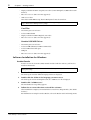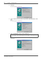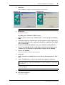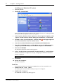
1
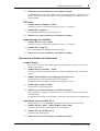
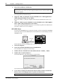
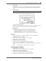
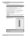
STUDIO MANAGER
for
Owner’s Manual
Keep This Manual For Future Reference.
E
i
Important Information
Important Information
Studio Manager Exclusion of Certain Liability
Manufacturer, importer, or dealer shall not be liable for any incidental damages including
personal injury or any other damages caused by improper use or operation of Studio Manager.
Trademarks
Apple and Macintosh are registered trademarks of Apple Computer, Inc. PowerPC is a registered trademark of International Business Machines Corporation. Pentium and Celeron
are registered trademarks of Intel Corporation. Microsoft and Windows are registered
trademarks of Microsoft Corporation. OMS is a registered trademark of Opcode Systems,
Inc. Adobe and Acrobat are registered trademarks of Adobe Systems Incorporated. SmartMedia is a trademark of Toshiba America, Inc. All other trademarks are the property of their
respective holders and are hereby acknowledged.
Copyright
No part of the Studio Manager software or this Owner’s Manual may be reproduced or distributed in any form or by any means without the prior written authorization of Yamaha
Corporation.
© 2002 Yamaha Corporation. All rights reserved.
Yamaha Web Site
Information about Studio Manager, related products, and other Yamaha professional audio
equipment is available on the Yamaha Professional Audio Web site at:
<http://www.yamaha.co.jp/product/proaudio/homeenglish/navi/index.htm>.
SPECIAL NOTICES
•
•
•
Use of the software and this guide is governed by the SOFTWARE LICENSING AGREEMENT which the purchaser fully agrees to upon breaking the seal of the software packaging.
(Please read carefully the AGREEMENT at the end of this guide before installing the application.)
Copying of the software or reproduction of this guide in whole or in part by any means is
expressly forbidden without the written consent of the manufacturer.
Yamaha makes no representations or warranties with regard to the use of the software and
documentation and cannot be held responsible for the results of the use of this guide and
the software.
Specifications and external appearance subject to change without notice.
Studio Manager—Owner’s Manual
ii
Contents
Contents
1
Getting Started . . . . . . . . . . . . . . . . . . . . . . . . . . . . 1
Introduction . . . . . . . . . . . . . . . . . . . . . . . . . . . . . . . . . . . . . . . . . . . . . . . . . . . . . . . . 1
Contents of the CD-ROM . . . . . . . . . . . . . . . . . . . . . . . . . . . . . . . . . . . . . . . . . . . . . 1
Minimum System Requirements . . . . . . . . . . . . . . . . . . . . . . . . . . . . . . . . . . . . . . . . 2
Software Installation for Windows . . . . . . . . . . . . . . . . . . . . . . . . . . . . . . . . . . . . . . 3
Software Installation for Macintosh . . . . . . . . . . . . . . . . . . . . . . . . . . . . . . . . . . . . . 8
Setting up OMS . . . . . . . . . . . . . . . . . . . . . . . . . . . . . . . . . . . . . . . . . . . . . . . . . . . . . 11
Connecting to the DM2000 . . . . . . . . . . . . . . . . . . . . . . . . . . . . . . . . . . . . . . . . . . . 12
Starting Studio Manager . . . . . . . . . . . . . . . . . . . . . . . . . . . . . . . . . . . . . . . . . . . . . . 13
Quitting Studio Manager . . . . . . . . . . . . . . . . . . . . . . . . . . . . . . . . . . . . . . . . . . . . . 13
Configuring Studio Manager . . . . . . . . . . . . . . . . . . . . . . . . . . . . . . . . . . . . . . . . . . 13
Using Studio Manager Online & Offline . . . . . . . . . . . . . . . . . . . . . . . . . . . . . . . . . 14
2
Console Window . . . . . . . . . . . . . . . . . . . . . . . . . . 15
Input Channels . . . . . . . . . . . . . . . . . . . . . . . . . . . . . . . . . . . . . . . . . . . . . . . . . . . . .
Master Section . . . . . . . . . . . . . . . . . . . . . . . . . . . . . . . . . . . . . . . . . . . . . . . . . . . . . .
Master Layer Channels . . . . . . . . . . . . . . . . . . . . . . . . . . . . . . . . . . . . . . . . . . . . . . .
Remote Layer Channels . . . . . . . . . . . . . . . . . . . . . . . . . . . . . . . . . . . . . . . . . . . . . .
3
Selected Channel Window . . . . . . . . . . . . . . . . . . 22
Input Channels . . . . . . . . . . . . . . . . . . . . . . . . . . . . . . . . . . . . . . . . . . . . . . . . . . . . .
Bus Outs . . . . . . . . . . . . . . . . . . . . . . . . . . . . . . . . . . . . . . . . . . . . . . . . . . . . . . . . . . .
Aux Sends . . . . . . . . . . . . . . . . . . . . . . . . . . . . . . . . . . . . . . . . . . . . . . . . . . . . . . . . . .
Stereo Out . . . . . . . . . . . . . . . . . . . . . . . . . . . . . . . . . . . . . . . . . . . . . . . . . . . . . . . . .
Matrix Sends . . . . . . . . . . . . . . . . . . . . . . . . . . . . . . . . . . . . . . . . . . . . . . . . . . . . . . .
Remote Channels . . . . . . . . . . . . . . . . . . . . . . . . . . . . . . . . . . . . . . . . . . . . . . . . . . .
4
16
18
20
21
22
24
25
27
28
29
Patch Editor Window . . . . . . . . . . . . . . . . . . . . . . 30
Input Patch Page . . . . . . . . . . . . . . . . . . . . . . . . . . . . . . . . . . . . . . . . . . . . . . . . . . . .
Output Patch Page . . . . . . . . . . . . . . . . . . . . . . . . . . . . . . . . . . . . . . . . . . . . . . . . . .
Insert Patch Page . . . . . . . . . . . . . . . . . . . . . . . . . . . . . . . . . . . . . . . . . . . . . . . . . . . .
Effect Patch Page . . . . . . . . . . . . . . . . . . . . . . . . . . . . . . . . . . . . . . . . . . . . . . . . . . . .
Direct Out Patch Page . . . . . . . . . . . . . . . . . . . . . . . . . . . . . . . . . . . . . . . . . . . . . . . .
30
31
32
33
34
5
Surround Editor Window . . . . . . . . . . . . . . . . . . . 35
6
GEQ Editor Window . . . . . . . . . . . . . . . . . . . . . . . 36
7
Timecode Counter Window . . . . . . . . . . . . . . . . . 37
8
Keyboard Shortcuts . . . . . . . . . . . . . . . . . . . . . . . . 38
Index . . . . . . . . . . . . . . . . . . . . . . . . . . . . . . . . . . . . . . 39
SOFTWARE LICENSING AGREEMENT . . . . . . . . . . . . . 40
Studio Manager—Owner’s Manual
1
Chapter 1—Getting Started
1 Getting Started
Introduction
The Yamaha Studio Manager for DM2000 allows you to control and display DM2000
parameters on your computer.
This Owner’s Manual contains information about installing and operating Studio Manager
for DM2000. Please refer to the DM2000 Owner’s Manual for detailed information on operating the DM2000.
Contents of the CD-ROM
Windows
Folder name
Software
Comments
Acroread_\English
Acrobat Reader1, 2
Allows you to read the PDF format documentation
SM_
Studio Manager for DM20001
Allows you to control and display DM2000
parameters on your computer
Card_
Card Filer1
You can transfer and manage DM2000 data
stored on SmartMedia cards.
Mididrv_
Yamaha CBX Driver
Driver software necessary for serial communication between your computer and the
DM2000.
USBdrv_
Yamaha USB MIDI Driver
(Windows 98, Me)
USBdrv2k_
Yamaha USB MIDI Driver
(Windows 2000, XP)
Driver software necessary for USB communication between your computer and the
DM2000.
1. An electronic (PDF) manual is included with this software. Refer to the electronic manual for information on using the software.
2. This software is not supported by Yamaha.
Mac
Folder name
Software
Comments
Acroread_\English
Acrobat Reader1, 2
Allows you to read the PDF format documentation
SM_
Studio Manager for DM2000 1
Allows you to control and display DM2000
parameters on your computer
Card_
Card Filer 1
You can transfer and manage DM2000 data
stored on SmartMedia cards.
Open Music System (OMS)
OMS_
USBdrv_
2.3.81, 2
Lets you use musical applications on Mac OS.
OMS Setup for YAMAHA
Contains sample OMS setup files for the
DM2000.
YAMAHA USB MIDI Driver
Driver software necessary for USB communication between your computer and the
DM2000.
1. An electronic (PDF) manual is included with this software. Refer to the electronic manual for information on using the software.
2. This software is not supported by Yamaha.
Studio Manager—Owner’s Manual
Minimum System Requirements
2
Minimum System Requirements
For Windows
Listed below are the minimum system requirements for a PC to run each item of software
supplied on the CD-ROM.
Note: Your operating system may have system requirements other than those specified for the
software.
Studio Manager for DM2000
•
•
•
•
•
A 433 MHz or faster Intel Pentium or Celeron processor
At least 128 MB of RAM
At least 20 MB of hard disk space
A VGA or better display with 1024 x 768 pixels, 256 colors (1280 x 1024, High Color 16-bit
recommended)
Microsoft Windows 98SE, Me, 2000, XP Home Edition, XP Professional Edition
Note that if you are using 1024 x 768 display resolution, select the Auto-hide option for the
Task Bar.
Card Filer
•
•
•
•
•
A 100 MHz or faster Intel Pentium or Celeron processor
At least 8 MB of RAM
At least 2 MB of hard disk space
A VGA or better display with 800 x 600 pixels, 256 colors
Microsoft Windows 95, 98, 98SE, Me, NT4.0, 2000, XP Home Edition, XP Professional Edition
Yamaha USB MIDI Driver
•
•
•
At least 32 MB of RAM
At least 2 MB of hard disk space
Microsoft Windows 98, 98SE, Me, NT4.0, 2000, XP Home Edition, XP Professional Edition
Yamaha CBX Driver
•
Microsoft Windows 95, 98, 98SE, Me, NT4.0, 2000, XP Home Edition, XP Professional Edition
For Mac
Listed below are the minimum system requirements for a Mac to run each item of software
supplied on the CD-ROM.
Note: Your operating system may have system requirements other than those specified for the
software.
Studio Manager for DM2000
•
•
•
A 233MHz PowerPC 604 processor or better (recommended: G3/300 MHz or better
equipped with USB)
At least 50 MB of RAM (virtual memory must be turned off)
At least 7MB of free hard disk space
Studio Manager—Owner’s Manual
3
Chapter 1—Getting Started
•
•
•
Display resolution of 1024 x 768 pixels, 256 colors (1280 x 1024 pixels, 32,000 colors recommended)
Mac OS 8.6 to 9.2.2 (Mac OS X not supported)
OMS 2.3.3 or later
Note that in OMS MIDI Setup, “Run in Background” must be turned on.
Note: If you are using a PowerBook and it is on battery power, go to “Power conservation settings” and deselect “Allow processor cycling.”
Card Filer
•
•
•
•
A PowerPC processor or better
At least 6 MB of RAM
Display resolution of 800 x 600 pixels, 256 colors
Mac OS 8.6 to 9.2.2 (Mac OS X not supported)
Yamaha USB MIDI Driver
•
•
•
•
•
A PowerPC processor or better
At least 64 MB of RAM (128 MB recommended)
At least 2 MB of hard disk space
USB port
Mac OS 8.6 to 9.2.2 (Mac OS X not supported)
Software Installation for Windows
Acrobat Reader
In order to view the electronic (PDF) manuals included with the software, you’ll need to
install Acrobat Reader.
Note: If an older version of Acrobat Reader is installed on your PC, you’ll need to uninstall it
before proceeding.
1
Double-click the “Acroread_” folder.
The folder opens and four different language folders are displayed.
2
Double-click the folder of the language you want to use.
The folder opens and for the English vesion, the “ar500enu.exe” file is displayed.
3
Double-click “ar500enu.exe.”
The Acrobat Reader setup dialog appears.
4
Follow the on-screen directions to install the software.
After installation is complete, an Acrobat folder is created in C:\ Program Files. (The default
location.)
For information on using the Acrobat Reader, refer to the Reader Guide in the Help menu.
Studio Manager—Owner’s Manual
Software Installation for Windows
4
USB MIDI Driver
To operate the DM2000 from your computer via USB, you’ll need to install the USB MIDI
driver. This software transfers MIDI data back and forth between Studio Manager and the
DM2000 via USB.
DM2000
Computer
Sequence
Software
USB cable
Driver
For Windows 98/Me, see the next section.
For Windows 2000, see page 6.
For Windows XP, see page 7.
Installing on a Windows 98/Me system
1
Turn on your PC and start Windows.
2
Insert the included CD-ROM disc into your CD-ROM or DVD-ROM drive.
3
Turn off the DM2000 and use a USB cable to connect the USB port of the
computer (or the USB hub) to the TO HOST USB port of the DM2000.
4
Turn on the DM2000.
The Add New Hardware Wizard window appears. If it does not appear, click Add New
Hardware in the Control Panel.
Note: For Windows Me, select “Automatic search for a better driver (Recommended)” and click
Next. When the driver is located and installed, proceed to Step 9. If the driver cannot be located,
select “Specify the location of the driver (Advanced)” and specify the CD-ROM drive’s root
directory (e.g., D:\) to install the driver.
Windows 98
Windows Me
Studio Manager—Owner’s Manual
5
Chapter 1—Getting Started
5
Click Next.
The window appears as shown below.
6
Select “Search for the best driver for your device. (Recommended).” Click
Next.
The window appears, as shown below.
7
Select “CD-ROM drive” only, as shown. Click Next.
Note: You may be asked to insert your Windows CD-ROM so that the driver can be located.
Specify the USBdrv_ folder of the CD-ROM (such as D:\USBdrv_\) and continue the installation.
When the driver is found, “YAMAHA USB MIDI Driver” is displayed in the window as
shown below.
Studio Manager—Owner’s Manual
Software Installation for Windows
8
6
Click Next.
After installation is complete, the window appears as shown below.
Windows 98
Windows Me
Note: It may take up to ten seconds for this window to appear.
9
Click Finish.
The driver is installed.
Installing on a Windows 2000 system
1
Turn on your PC and use the “Administrator” account to log into Windows
2000.
2
Select My Computer, Control Panel, System, Hardware, Driver Signing, File
Signature Verification, select “Ignore -Install all files, regardless of file signature,” and click OK.
3
Insert the included CD-ROM disc into your CD-ROM or DVD-ROM drive.
4
Turn off the DM2000 and use a USB cable to connect the USB port of the
computer (or the USB hub) to the TO HOST USB port of the DM2000.
5
Turn on the DM2000.
The Add New Hardware Wizard window appears.
6
Click Next.
7
Select “Search for a suitable driver for my device. (Recommended).” Click
Next.
8
Select “CD-ROM drives” only, in the window that appears. Click Next.
Note: You may be asked to insert your Windows CD-ROM so that the driver can be located.
Specify the “USBdrv2k_” folder of the CD-ROM drive (such as D:\USBdrv2k_\) and continue
the installation.
When the installation is complete the message, “Completing the Found New Hardware
Wizard” is displayed.
Note: It may take up to ten seconds for this window to appear.
9
Click Finish.
10 Restart the computer.
The driver is installed.
Studio Manager—Owner’s Manual
7
Chapter 1—Getting Started
Installing on a Windows XP system
1
Turn on your PC.
2
Click Start, Control Panel.
If the Control Panel is displayed as shown, click “Switch to classic view” in the upper left of
the window. All control panels and icons are displayed.
3
Select System, Hardware, Driver signatures, Driver signature options, select
“Ignore—Install software without asking for confirmation,” and click OK.
4
Click OK to close System Properties, and then click
ner of the window to close the Control Panel.
5
Insert the included CD-ROM into your CD-ROM or DVD-ROM drive.
6
Turn off the DM2000 and use a USB cable to connect the USB port of the
computer (or the USB hub) to the TO HOST USB port of the DM2000.
7
Turn on the DM2000.
The Found New Hardware Wizard window appears.
8
Select “Install software automatically (recommended) (I),” and click Next.
When the installation is complete the message, “Completing the Found New Hardware
Wizard” is displayed.
in the upper right cor-
Note: It may take up to ten seconds for this window to appear.
9
Click Finish.
10 Restart the computer.
The driver is installed.
Card Filer
1
2
If you install Card Filer, you can manage DM2000 data stored on SmartMedia cards.
Double-click the “Card_” folder.
The folder opens and various files including “Setup.exe” are displayed.
Double-click “Setup.exe.”
The YAMAHA Card Filer setup dialog appears.
Studio Manager—Owner’s Manual
Software Installation for Macintosh
3
8
Follow the on-screen directions to install the software.
A YAMAHA folder is created in C:\Program Files (the default location). The files for Card
Filer are created inside that folder. Refer to “Card Filer Manual.pdf” for information on
using Card Filer.
CBX Driver
1
Double-click the “Mididrv_” folder.
The folder opens and various files including “Setup.exe” are displayed.
2
Double-click “Setup.exe.”
The YAMAHA CBX Driver setup dialog appears.
3
Follow the on-screen directions to install the software.
Studio Manager for DM2000
1
Double-click the “SM_” folder.
The folder opens and various files including “Setup.exe” are displayed.
2
Double-click “Setup.exe.”
The Studio Manager for DM2000 setup dialog appears.
3
Follow the on-screen directions to install the software.
Software Installation for Macintosh
Acrobat Reader
1
In order to view the electronic (PDF) manuals included with the software, you’ll need to
install Acrobat Reader.
Double-click the “Acrobat_” folder.
The folder opens and four language folders are displayed: English, French, German, and
Japanese.
2
Double-click the folder of the language you want to use.
The folder opens and the “Reader Installer” file is displayed.
The Installer name may differ depending on the language you select.
3
Double-click “Reader Installer.”
Acrobat Reader setup dialog appears.
4
Follow the on-screen directions to install the software.
After installation is complete, an Acrobat folder is created on your Mac’s startup disk (the
default location).
For information on using the Acrobat Reader, refer to the Reader Guide in the Help menu.
Open Music System (OMS) 2.3.8
1
OMS allows you to use several MIDI applications on the Mac OS at the same time.
Double-click the “OMS_” folder (English version only).
The folder opens and the “Install OMS 2.3.8” file is displayed.
2
Double-click “Install OMS 2.3.8.”
The OMS setup dialog appears.
3
Follow the on-screen directions to install the software.
Studio Manager—Owner’s Manual
9
Chapter 1—Getting Started
4
After the installation, click Restart.
Note: After the installation is complete, you may encounter an error message warning that the
installer did not close. In this case, choose Quit from the File menu to close the installer. Then
restart the computer.
After restarting, the Opcode folder is created containing the OMS Applications folder (on
the startup disk as the default location).
5
Copy the “OMS_2.3_Mac.pdf” on the CD-ROM to the “OMS Applications”
folder (drag-and-drop it to the folder).
Refer to the “OMS_2.3_Mac.pdf” (English version only) for information on how to use
OMS.
6
Copy the “OMS Setup for YAMAHA” on the CD-ROM to the “OMS Applications” folder (drag-and-drop it to the folder).
In the “OMS Setup for YAMAHA” folder there are the OMS Setup files for the Yamaha tone
generators, which can be used as templates.
USB MIDI Driver
To operate the DM2000 from your computer via USB, you’ll need to install the USB MIDI
driver. This software transfers MIDI data back and forth between Studio Manager and the
DM2000 via USB.
DM2000
Computer
Sequence
Software
OMS
1
USB cable
Driver
Install OMS first, then the USB MIDI driver, and then set up OMS.
Start the computer.
2
Insert the included CD-ROM into the CD-ROM drive.
The CD-ROM icon is displayed on the desktop.
3
Double-click the CD-ROM icon and double-click the “USBdrv_” folder.
4
Double-click “Install USB Driver.”
The Install USB Driver setup dialog appears, as shown below.
The “Install Location” displays the destination of the installation.
5
If you want to change the destination disk or folder, click the Switch Disk
button and use the pop-up menu to specify the destination.
Note: This pop-up menu usually displays the startup disk as the destination.
Studio Manager—Owner’s Manual
Software Installation for Macintosh
10
6
Click Install.
The following message appears: “This installation requires your computer to restart after
installing this software. Click Continue to automatically quit all other running applications.”
7
Click Continue.
Note: To cancel the installation, click Cancel.
The installation starts.
If the driver has already been installed, the following message appears.
To quit the installation, click Quit.
When the installation is complete, the following message appears: “Installation was successful. You have installed software which requires you to restart your computer.”
8
Click Restart.
The computer restarts. The installed files are in the following locations:
• YAMAHA USB MIDI Patch is located in System Folder\Control Panels
• USB YAMAHA MIDI Driver is located in System Folder\Extensions
• YAMAHA USB MIDI OMS Driver is located in System Folder\OMS Folder
Card Filer
1
If you inst Card Filer, you can manage DM2000 data stored on SmartMedia cards.
Double-click the “Card_” folder.
The folder opens and the “Card Filer Installer” file is displayed.
2
Double-click “Card Filer installer.”
The Install Card Filer setup dialog appears.
3
Follow the on-screen directions to install the software.
A “Card Filer 1.0.3 for DM2000” folder is created on the startup hard disk (the default location).
Refer to “Card Filer Manual.pdf” for information on using Card Filer.
Studio Manager for DM2000
1
Double-click the “SM_” folder.
The folder opens and the “Install Studio Manager” file is displayed.
2
Double-click “Install Studio Manager.”
The Install Studio Manager for DM2000 setup dialog appears.
3
Follow the on-screen directions to install the software.
Studio Manager—Owner’s Manual
11
Chapter 1—Getting Started
Setting up OMS
OMS Studio Setup files for the DM2000 are supplied on the included CD-ROM. The setup
files are used for setting up OMS when using the serial or USB ports.
Note: When using USB, OMS and the USB MIDI driver should be installed before proceeding.
1
Turn off the DM2000 and use a USB cable to connect the USB port of the
computer (or the USB hub) to the TO HOST USB port of the DM2000.
2
Turn on the DM2000 and start the computer.
3
Insert the included CD-ROM into the CD-ROM drive of your Mac.
The CD-ROM icon appears on the desktop.
4
Double-click the CD-ROM icon, “OMS_”, and “OMS Setup for YAMAHA.”
Three files “DM2000-Modem,” “DM2000-Printer,” and “DM2000-USB” appear. Copy
these to the hard disk on your computer.
5
Double-click one of “DM2000-Modem” or “DM2000-Printer” or
“DM2000-USB” to start OMS Setup.
The setup files are used as follows.
DM2000-Modem: Used when connecting the modem port of your Mac to the DM2000.
DM2000-Printer: Used when connecting the printer port of your Mac to the DM2000.
DM2000-USB: Used when connecting the USB port of your Mac to the DM2000.
Note: A USB hub is necessary when several DM2000s are connected to the computer.
After starting the OMS Setup, the selected
Studio Setup file opens. The
DM2000-USB version is shown on the
right.
Indicates this setup is available
Note: When using either of the serial ports (modem or printer), go to OMS Setup Preferences
and deselect “Use Apple DMA driver when available.”
Note: If “ ” is not indicated next to the setup file name, choose Make Current from the File
menu, and then Save.
Studio Manager—Owner’s Manual
Connecting to the DM2000
12
The OMS studio setup is complete.
Note: After the OMS Studio Setup above has been completed, your computer will recognize
only the DM2000 as a MIDI instrument. If you use another MIDI instrument in addition to
the DM2000,or you add a second DM2000 to the existing system, you should create an original
Studio Setup file. Refer to the on-line manual supplied with OMS for more information.
Note: Depending on your Mac and Mac OS version, the included OMS Studio Setup file may
not function (i.e., MIDI data cannot be transmitted/received even though the settings have
been made.)
In this case, connect your Mac to the DM2000 via USB and follow the procedure below to recreate the setup file.
1
Start OMS Setup and choose “New Setup” from the File menu.
The OMS Driver Search dialog appears.
2
Deselect “Modem” and “Printer,” and click Search.
If successful, the USB-MIDI device is displayed in the OMS driver setting dialog.
3
Click OK to search for ports.
Port 1, Port 2... appears in the dialog.
4
Select the appropriate ports and click OK to store the setting.
Refer to “OMS_2.3_Mac.pdf” supplied with OMS for more information.
Connecting to the DM2000
Select the port and ID on the DM2000 that you want to use for communication with Studio
Manager. To select a port and ID, locate the MIDI/TO HOST Setup page of the DM2000
and make the selections as required. If you are using the serial port to connect to the
DM2000, select the type that matches your computer’s serial port. You can select either
PC-2 or Mac. See the DM2000 documentation for more information.
Note: Turn off the DM2000 and shut down the computer if you connecting using the serial or
MIDI ports
Connection Alternatives
DM2000 Rear Panel
Mac or PC
1. Serial
Serial cable
Serial port
2. USB
USB cable
USB port
3. MIDI
MIDI Interface
MIDI cables
Studio Manager—Owner’s Manual
13
Chapter 1—Getting Started
Starting Studio Manager
For Windows, click the “Start” button and select Programs, YAMAHA Studio Manager,
DM2000, Studio Manager for DM2000.
For Mac, open the Studio Manager folder and double-click “YAMAHA Studio Manager for
DM2000.”
Studio Manager displays its startup screen, shown below, and then takes a few seconds to
initialize itself before opening the Console window.
Quitting Studio Manager
Choose Quit from the File menu.
If all changes have been saved, all windows close and Studio Manager quits. If there are any
unsaved changes, a message asking if you want to save the changes appears. Click Yes to save
the changes and quit, No to quit, or Cancel to cancel the operation.
Studio Manager can also be quit by clicking the Close button in the upper-left corner of the Console window on the Mac, or the upper-right corner in Windows.
Configuring Studio Manager
You must select an input and output port, and a Console Device ID so that Studio Manager
can communicate with the DM2000.
Selecting Ports
Ports can be selected in Windows by choosing Setup from the File menu.
Ports can be selected on the Mac by choosing Select OMS Ports from the File menu. OMS
MIDI Setup, OMS Studio Setup, and the System setup dialog are also accessible from the
File menu. See the OMS documentation for more information on OMS. The System setup
dialog is not part of OMS and is described in the next section.
System setup dialog
To open the dialog, select it from the File menu. This dialog is used to select one of eight
Console Device IDs. You must ensure that the DM2000 you want to communicate with is
set to the same ID. From here, you can turn on and off Studio Manager’s control of channel
and Layer selection on the DM2000, and the DM2000’s control of channel and Layer selection in Studio Manager, and also choose whether or not you want DM2000 patching confirmed before carrying it out. On the Windows version, the dialog is also used to select input
and output ports for Studio Manager.
Studio Manager—Owner’s Manual
Using Studio Manager Online & Offline
14
Shown below left is the Mac version of the dialog, and below right is the Windows version.
Using Studio Manager Online & Offline
When Studio Manager is started, it opens a new Session using its default settings and checks
whether an active DM2000 is connected, active meaning connected and turned on. If an
active DM2000 is detected, a message appears asking whether or not you want to transfer
the settings of the Studio Manager Session to the DM2000 (PC –>Console), or transfer the
settings of the DM2000 to the Studio Manager Session (Console–>PC), or neither (CANCEL). After you have selected your option, the ONLINE/OFFLINE status indicator of the
Console window displays whether Studio Manager is online or offline accordingly.
Note: Do not operate the DM2000 while Studio Manager is synchronizing. Wait until the
ONLINE/OFFLINE status indicator shows “ONLINE.” This ensures that the settings on the
DM2000 and in Studio Manager are the same.
If no active DM2000 is detected, no messages appear and a new Session opens using the
default settings. If an active DM2000 is detected after Studio Manager was started, the same
message appears as described previously.
If you want to change to online or offline at any time later, choose Re-synchronize... from
the Studio Manager Synchronization menu, and the same message appears as described
previously.
Only one Studio Manager Session can be open at a time. If a Session is open, and you want
to open another, either a previously saved Session or a new one, a message appears warning
that the current Session will be overwritten if you continue. If Studio Manager is offline and
you continue, the Session is loaded. If Studio Manager is online and you continue, the Session is loaded and the same message appears as described previously, asking if you want to
transfer the settings of the Session to the DM2000, or transfer the settings from the DM2000
(which can be used as an Undo function), or neither.
Note that there is an All Lib option in the message window described above. This is used to
select whether or not the contents of the libraries are transferred.
Note: In Version 1.0 of Studio Manager for DM2000, the settings of a Session can include
library information, however you cannot edit the contents of the libraries as there is no Library
window.
Note: When you execute a Library Sort operation on the DM2000, you must synchronize Studio Manager after wards. To do this choose Re-synchronize from the Synchronization menu
and ensure that the All Lib option just described is selected before synchronizing.
Studio Manager—Owner’s Manual
15
Chapter 2—Console Window
2 Console Window
The Console window is Studio Manager’s main window and opens when Studio Manager
is started. It provides an overview of the mixer channels, and most major functions can be
operated from here. The window is divided into the Channel Section and the Master Section. The Channel Section displays a Layer (24 channels) at a time, and Layers can be
selected by using the LAYER buttons in the Master Section.
Channel Section
Studio Manager—Owner’s Manual
Master Section
Input Channels
16
Input Channels
An Input Channel from the Console window is shown below.
A SOURCE parameter
1
B
C
D
5
6
7
8
9
J
K
L
M
N
O
P
Q
This parameter is used to select an Input source. To select an
Input source, click the parameter and choose from the list that
appears.
B Bus Out routing buttons
These buttons are used to route the Input Channel’s signal to
one or more of the Bus Outs.
C STEREO button
This button is used to route the Input Channel’s signal to the
Stereo Out.
D DIRECT button
This button turns on and off the Input Channel’s routing to its
Direct Out.
E Direct Out destination
This parameter is used to select a Direct Out destination. To
select a destination, click the parameter and choose from the list
that appears.
F PHASE button
This button is used to reverse the signal phase of the channel.
G INSERT button
This button is used to turn on and off the Input Channel’s Insert.
R
H GATE button
This button is used to turn on and off the Input Channel’s Gate.
I Gate open & closed indicators
These indicators display whether the Gate is open (green) or
closed (red), when the Gate is turned on.
S
J Gate Threshold display
T
V
This display shows the Threshold setting of the Gate. The value
can be set by dragging.
U
K COMP button
W
This button is used to turn on and off the Input Channel’s ComX
Y
pressor.
Z
L Compressor curve display
This display shows the Compressor’s curve.
M EQ button
a
This button is used to turn on and off the Input Channel’s
4-band Parametric Equalizer.
N EQ curve display
This display shows the Equalizer’s curve, which
can be set by dragging.
b
O DELAY button
This button is used to turn on and off the Input Channel’s Delay
function.
Studio Manager—Owner’s Manual
17
Chapter 2—Console Window
P Delay Time
This parameter is used to set the delay time of the Delay function. Delay times can be set by
dragging.
Q Channel number
Displays the Channel number of the channel.
R AUX section
These controls are used to set the levels of the 12 Aux Sends. To turn an Aux Send
on or off, click its number. To set an Aux Send level, drag the end of the bar next
to the Aux Send’s number or click a point along the length of the bar.
The table below shows how the Input Channel’s Aux Send controls appear
depending on their status. See page 23 for information on how to switch Aux
Sends to pre-fader or post-fader positions.
Aux Send status
Bar appearance on Input Channel
Either on or off but no level set
Dark blue bar
Off, pre-fader
Green bar outline displays level
On, pre-fader
Green bar displays level
Off, post-fader
Orange bar outline displays level
On, post-fader
Orange bar displays level
S Pan/Aux Send
This parameter shows either the stereo or surround pan position and, during Aux Send setting, the parameter shows the Aux Send level in dB.
T Pan control
This control is used to set the Input Channel’s stereo or surround pan position. When the
PAN CONTROL in the Master Section is set to “STEREO,” the Pan control appears as a
rotary control, and when set to “SURR,” the control appears as dot on a pan graph. The surround pan position can be set by dragging the dot.
U LFE control
This control is used to set the surround LFE Channel level. It appears when the
PAN CONTROL in the Master Section is set to “SURR.” To set the LFE level,
drag the end of its bar or click a point along the length of the bar.
V AUTO button
This button is not used in Version 1.0 of Studio Manager for DM2000.
W SELECT button
This button is used to select the Input Channel.
X SOLO button
This button solos the Input Channel and is colored orange when the channel is soloed.
Y ON button
This button turns the Input Channel on and off. It is colored orange when the channel is
turned on.
Z Short Channel name
This is the channel’s Short Channel name, which can be edited. To edit the name, click it
and type.
a Channel Fader
This control is used to set the level of the Input Channel.
b Channel Meter
This meter displays the signal level of the Input Channel.
Studio Manager—Owner’s Manual
Master Section
18
Master Section
The Master Section is situated on the right side of the Console window.
1
A ONLINE/OFFLINE status indicator
This indicator shows whether Studio Manager is online
or offline. See “Using Studio Manager Online & Offline”
on page 14 for more information.
B Meters (Stereo shown)
2
These meters display the output level of the Stereo Out
when the PAN CONTROL is set to “STEREO,” and the
Bus Outs when the PAN CONTROL is set to “SURR.” See
page 19 for information on how these meters appear in
Surround modes 3-1 and 5.1.
C LAYER buttons
These buttons are used to select the Layers. The channels
of the selected Layer are displayed in the Channel Section
of the Console window. Only one Layer can be selected at
a time.
D PAN CONTROL
These two buttons are used to select either “STEREO”
(Stereo mode) or “SURR” (Surround mode). The Pan
control on the Input Channels is a rotary control when
“STEREO” is selected, and a dot on a pan graph when
“SURR” is selected.
E AUTO button
3
This button is not used in Version 1.0 of Studio Manager
for DM2000.
F SELECT button
4
This button is used to select the Stereo Out. Note that the
Stereo Out cannot be selected if a Remote Layer is
selected.
G ON button
This button turns the Stereo Out on and off. It is colored
orange when the Stereo Out is turned on.
5
6 H Channel Fader
7
This control is used to set the level of the Stereo Out.
8
Studio Manager—Owner’s Manual
19
Chapter 2—Console Window
Master Section Meters
If the PAN CONTROL is set to “SURR” (Surround
mode), the Meters display the levels of the Bus Outs
used for surround processing. Shown on the right are
how the Meters appear in 3-1 and 5.1 Surround modes.
In 3-1 Surround mode, Bus Outs 1 to 4 levels are
labelled as the Left, Center, Right, and Surround channels respectively.
In 5.1 Surround mode, Bus Outs 1 to 6 levels are
labelled as the Left, Center, Right, Left & Right Surround, and Low Frequency Effect channels respectively.
3-1
Studio Manager—Owner’s Manual
5.1
Master Layer Channels
20
Master Layer Channels
When the Master Layer is selected in the Master Section, the Bus Outs, Aux Sends, and
Matrix Sends can be selected. A Bus Out is shown below. Aux Sends and Matrix Sends
appear the same except that they do not have a STEREO button.
A STEREO button (Bus Out only)
This button is used to route the Bus Out to the Stereo Out.
B INSERT button
This button is used to turn on and off the Bus Out’s Insert.
1 C COMP button
This button is used to turn on and off the Bus Out’s Compressor.
D Compressor curve display
2
This display shows the Compressor’s curve.
E EQ button
C
This button is used to turn on and off the Bus Out’s 4-band Parametric Equalizer.
D F EQ curve display
This display shows the Equalizer’s curve, which can be set by
5
dragging.
6 G DELAY button
7
This button is used to turn on and off the Bus Out’s Delay func8
tion.
I
H Delay time
This parameter is used to set the delay time of the Delay function. Delay times can be set by dragging.
I Channel number
Displays the Channel number of the channel.
J AUTO button
This button is not used in Version 1.0 of Studio Manager for
DM2000.
K SELECT button
This button is used to select the Bus Out.
J L SOLO button
This button solos the Bus Out and is colored orange when the
K
channel is soloed.
L
M M ON button
N
This button turns the Bus Out on and off. It is colored orange
when the channel is turned on.
O N Short Channel name
This is the channel’s Short Channel name, which can be edited.
To edit the name, click it and type.
O Channel Fader
This control is used to set the level of the Bus Out.
P P Channel Meter
This meter displays the signal level of the Bus Out.
Studio Manager—Owner’s Manual
21
Chapter 2—Console Window
Remote Layer Channels
When a Remote Layer is selected in the Master Section, Remote Channels can be selected.
A Channel number
Displays the Channel number of the channel.
B SELECT button
This button is used to select the Remote Channel.
C ON button
This button turns the Remote Channel on and off. It is colored
orange when the channel is turned on.
D Short Channel name
This is the channel’s Short Channel name, which can be edited.
To edit the name, click it and type.
E Channel Fader
This control is used to set the level of the Remote Channel.
1
2
C
D
5
Studio Manager—Owner’s Manual
22
Selected Channel Window
3 Selected Channel Window
•
•
•
•
•
•
To open the Selected Channel window, choose Selected Channel from the Windows menu.
The Selected Channel window is used for displaying and editing a single channel in detail.
Its content varies depending on the selected channel’s facilities. There are six variations of
the Selected Channel window, they are:
Input Channel. See below.
Bus Out. See page 24.
Aux Send. See page 25.
Stereo Out. See page 27.
Matrix Send. See page 28.
Remote Channel. See page 29.
Input Channels
The Selected Channel window for the Input Channels is shown below.
1
8
2 3
9
4 5
6
7
J
A CHANNEL SELECT section
Channels can be selected by clicking the Channel ID and selecting from the list that appears,
or by clicking the left and right Channel Select buttons. This section also displays the Long
Channel name which can be edited. To edit the name, click it and type. The LIBRARY button is not used in Version 1.0 of Studio Manager for DM2000.
B GATE section
This section contains the controls and display graph for the currently selected Input Channel’s Gate. The rotary controls are used to set the threshold level, range level, attack, decay,
Studio Manager—Owner’s Manual
23
Chapter 3—Selected Channel Window
and hold time of the Gate, and the Gate’s curve is drawn on its display graph. The GR meter
indicates the level of gain reduction being applied by the Gate. The ON button turns the
Gate on and off, and the LINK button is used to pair the Gate of the currently selected Input
Channel with its adjacent channel, with the Pair mode setting on the DM2000 determining
whether pairing is horizontal or vertical. If the channel is paired, the LINK button cannot
be turned off until pairing is turned off. The KEY IN parameter is used to select a trigger
source for the Gate. The LIBRARY button is not used in Version 1.0 of Studio Manager for
DM2000.
C The INPUT PATCH parameter
This parameter is used to select an Input source. To select an Input, click the parameter and
choose from the list that appears.
D EQUALIZER section
This section contains the controls and display graph for the currently selected Input Channel’s 4-band Parametric Equalizer. The rotary controls are used to set the gain, center frequency, and Q of each band, and the pre-EQ attenuation level. The Equalizer curve, which
can also be set by dragging, is drawn on its display graph. The ON button turns the Equalizer on and off, and the TYPE buttons are used to select the Equalizer type. The LIBRARY
button is not used in Version 1.0 of Studio Manager for DM2000.
E DELAY/PHASE section
This section contains the controls for the currently selected Input Channel’s Delay function.
The rotary controls are used to set the delay time, feedback gain, and feedback mix of the
delayed signal. The ON button turns the Delay function on and off, and the PHASE button
is used to reverse the signal phase of the channel.
F Routing/Pan/Level section
This section contains the controls for the currently selected Input Channel’s Routing, Pan,
Level, and other functions described here. The ROUTING buttons (1 to 8) are used to route
the channel to the Bus Outs. The STEREO button is used to route the channel to the Stereo
Out. The DIRECT button turns on and off the channel’s routing to its Direct Out and the
parameter below it selects a Direct Out destination. The F.PAN button turns on and off the
Follow Pan function on the Bus Outs, and the PAN control is used to set the Pan position
of the channel on the Stereo Out and Bus Outs. The SOLO button is used to solo the channel, the ON button to turn on and off the channel, and the Channel Fader to set the channel
level. The AUTO button is not used in Version 1.0 of Studio Manager for DM2000.
G AUX SEND section
This section contains the controls for the currently selected Input Channel’s Aux
Sends, and indicates whether any Aux Sends are paired with a heart. The rotary controls are used to set the Aux Send levels of the channel and turn them on and off. To turn an
Aux Send on or off, click its rotary control. The button below each Aux Send is used to select
whether the Aux Send is placed pre-fader or post-fader.
H COMPRESSOR section
This section contains the controls and display graph for the currently selected Input Channel’s Compressor. The rotary controls are used to set the threshold level, ratio, the attack
and release times, the output gain, and knee shape of the Compressor. The Compressor’s
curve is drawn on its display graph. The GR meter indicates the level of gain reduction
applied by the Compressor, and the OUT meter indicates its output level. The ON button
turns the Compressor on and off, and the LINK button is used to pair the Compressor of
the currently selected channel with its adjacent channel, with the Pair mode setting on the
DM2000 determining whether pairing is horizontal or vertical. If the channel is paired, the
LINK button cannot be turned off until pairing is turned off. The POSITION parameter is
used to specify the position of the Compressor in the currently selected Input Channel’s signal path, and the ORDER parameter to select whether the Insert feeds the Compressor or
vice versa when they are set to the same position in the channel. The LIBRARY button is not
used in Version 1.0 of Studio Manager for DM2000.
Studio Manager—Owner’s Manual
Bus Outs
24
I INSERT section
This section contains the parameters for the currently selected Input Channel’s Insert. The
INSERT button turns the Insert on and off. The OUT and IN parameters are used to select
the channel’s Insert Out and Insert In, and the POSITION parameter is used to specify the
Insert’s position in the channel’s signal path.
J FADER GROUP/MUTE GROUP section
This section contains the buttons for assigning the currently selected Input Channel to the Fader Groups and Mute Groups. Click the Heart Mark to pair the channel
with its adjacent channel.
Bus Outs
The Selected Channel window for the Bus Outs is shown below.
1
5
2
6
3
4
7
A CHANNEL SELECT section
Channels can be selected by clicking the Channel ID and selecting from the list that appears,
or by clicking the left and right Channel Select buttons. This section also displays the Long
Channel name, which can be edited. To edit the name, click it and type. The LIBRARY button is not used in Version 1.0 of Studio Manager for DM2000.
B EQUALIZER section
This section contains the controls and display graph for the currently selected Bus Out’s
4-band Parametric Equalizer and is identical to the Equalizer section of the Input Channels.
See page 23.
C DELAY section
This section contains the controls for the currently selected Bus Out’s Delay function. The
rotary control is used to set the delay time, and the ON button turns the Delay function on
and off.
Studio Manager—Owner’s Manual
25
Chapter 3—Selected Channel Window
D Bus Out Routing/Pan/Level section
This section contains the controls for the currently selected Bus Out’s routing, pan, and level
functions. The TO STEREO button turns on and off the Bus to Stereo routing, and the
rotary controls are used to set the Bus to Stereo level and Pan position. The SOLO button is
used to solo the Bus Out, the ON button to turn the Bus Out on and off, and the Channel
Fader to set the Bus Out level. The AUTO button is not used in Version 1.0 of Studio Manager for DM2000.
E COMPRESSOR section
This section contains the controls and display graph for the currently selected Bus Out’s
Compressor and is identical to the Compressor section of the Input Channels. See page 23.
F INSERT section
This section contains the parameters for the currently selected Bus Out’s Insert. The
INSERT button turns the Insert on and off. The OUT and IN parameters are used to select
the channel’s Insert Out and Insert In, and the POSITION parameter is used to specify the
Insert’s position in the channel’s signal path.
G FADER GROUP/MUTE GROUP section
This section contains the buttons for assigning the currently selected Bus Out to the Fader
Groups and Mute Groups. Click the Heart Mark to pair the channel with its adjacent channel.
Aux Sends
The Selected Channel window for the Aux Sends is shown below.
1
5
2
6
3
4
7
A CHANNEL SELECT section
Channels can be selected by clicking the Channel ID and choosing from the list that
appears, or by clicking the left and right Channel Select buttons. This section also displays
Studio Manager—Owner’s Manual
Aux Sends
26
the Long Channel name, which can be edited. To edit the name, click it and type. The
LIBRARY button is not used in Version 1.0 of Studio Manager for DM2000.
B EQUALIZER section
This section contains the controls and display graph for the currently selected Aux Send’s
4-band Parametric Equalizer and is identical to the Equalizer section of the Input Channels.
See page 23.
C DELAY section
This section contains the controls for the currently selected Aux Send’s Delay function. The
rotary control is used to set the delay time, and the ON button turns the Delay function on
and off.
D Aux Send Level section
This section contains the Channel ON button, the SOLO button, and the Channel Fader for
the currently selected Aux Send. The AUTO button is not used in Version 1.0 of Studio
Manager for DM2000.
E COMPRESSOR section
This section contains the controls and display graph for the currently selected Aux Send’s
Compressor and is identical to the Compressor section of the Input Channels. See page 23.
F INSERT section
This section contains the parameters for the currently selected Aux Send’s Insert. The
INSERT button turns the Insert on and off. The OUT and IN parameters are used to select
the channel’s Insert Out and Insert In, and the POSITION parameter is used to specify the
Insert’s position in the channel’s signal path.
G FADER GROUP/MUTE GROUP section
This section contains the buttons for assigning the currently selected Aux Send to the Fader
Groups and Mute Groups. Click the Heart Mark to pair the channel with its adjacent channel.
Studio Manager—Owner’s Manual
27
Chapter 3—Selected Channel Window
Stereo Out
The Selected Channel window for the Stereo Out is shown below. Note that this window
cannot be opened from the Windows menu if a Remote Layer is selected.
1
5
2
6
3
4
7
A CHANNEL SELECT section
Channels can be selected by clicking the Channel ID and choosing from the list that
appears, or by clicking the left and right Channel Select buttons. This section also displays
the Long Channel name, which can be edited. To edit the name, click it and type. The
LIBRARY button is not used in Version 1.0 of Studio Manager for DM2000.
B EQUALIZER section
This section contains the controls and display graph for the Stereo Out’s 4-band Parametric
Equalizer and is identical to the Equalizer section of the Input Channels. See page 23.
C DELAY section
This section contains the controls for the Stereo Out’s Delay function. The rotary control is
used to set the delay time, and the ON button turns the Delay function on and off.
D Stereo Out Pan/Level section
This section contains the Pan control, Channel ON button, and the Channel Fader for the
Stereo Out. The AUTO button is not used in Version 1.0 of Studio Manager for DM2000.
E COMPRESSOR section
This section contains the controls and display graph for the Stereo Out’s Compressor and is
identical to the Compressor section of the Input Channels except that there is no LINK button. See page 23.
F INSERT section
This section contains the parameters for the Stereo Out’s Insert. The INSERT button turns
the Insert on and off. The OUT and IN parameters are used to select the channel’s Insert
Studio Manager—Owner’s Manual
Matrix Sends
28
Out and Insert In, and the POSITION parameter is used to specify the Insert’s position in
the channel’s signal path.
G FADER GROUP/MUTE GROUP section
This section contains the buttons for assigning the Stereo Out to the Fader Groups and
Mute Groups.
Matrix Sends
The Selected Channel window for the Matrix Sends is shown below.
1
2
3
4
8
5
9
6
7
J
A AUX section
This section contains the controls for the currently selected Matrix Send’s inputs from the
Aux Sends. The rotary controls are used to set each Aux Send’s Pan position and Level for
the Matrix Send. Paired Aux Sends are indicated by a heart.
B BUS section
This section contains the controls for the currently selected Matrix Send’s inputs from the
Bus Outs. The rotary controls are used to set each Bus Out’s Pan position and Level for the
Matrix Send. Paired Bus Outs are indicated by a heart.
C STEREO section
This section contains the controls for the currently selected Matrix Send’s inputs from the
Stereo Out. The rotary controls are used to set the Stereo Out’s Pan position and Level for
the Matrix Send.
D CHANNEL SELECT section
Channels can be selected by clicking the Channel ID and choosing from the list that
appears, or by clicking the left and right Channel Select buttons. This section also displays
the Long Channel name, which can be edited. To edit the name, click it and type. The
LIBRARY button is not used in Version 1.0 of Studio Manager for DM2000.
E EQUALIZER section
This section contains the controls and display graph for the Matrix Send’s 4-band Parametric Equalizer and is identical to the Equalizer section of the Input Channels. See page 23.
Studio Manager—Owner’s Manual
29
Chapter 3—Selected Channel Window
F DELAY section
This section contains the controls for the currently selected Matrix Send’s Delay function.
The rotary control is used to set the delay time, and the ON button turns the Delay function
on and off.
G Matrix Send Level section
This section contains the ChannelON button, the SOLO button, and the Channel Fader for
the currently selected Matrix Send. The AUTO button is not used in Version 1.0 of Studio
Manager for DM2000.
H COMPRESSOR section
This section contains the controls and display graph for the currently selected Matrix Send’s
Compressor and is identical to the Compressor section of the Input Channels except that
there is no LINK button. See page 23.
I INSERT section
This section contains the parameters for the currently selected Matrix Send’s Insert. The
INSERT button turns the Insert on and off. The OUT and IN parameters are used to select
the channel’s Insert Out and Insert In, and the POSITION parameter is used to specify the
Insert’s position in the channel’s signal path.
J Fader Group/Mute Group section
This section contains the buttons for assigning the currently selected Matrix Send to the
Fader Groups and Mute Groups.
Remote Channels
The Selected Channel window for the
Remote Channels.
A CHANNEL SELECT section
1
Channels can be selected by clicking the
Channel ID and choosing from the list that
appears, or by clicking the left and right
Channel Select buttons. This section also
displays the Long Channel name, which can
be edited. To edit the name, click it and type.
B Remote Channel Level section
This section contains the Channel ON button, and the Channel Fader for the currently
selected Remote Channel.
Studio Manager—Owner’s Manual
2
Patch Editor Window
30
4 Patch Editor Window
To open the Patch Editor window, choose Patch Editor from the Windows menu. The Patch
Editor window’s five pages are used to patch Inputs, Outputs, Inserts, Direct Outs, and
Effects. Pages can be selected by clicking the tabs along the top of the window.
Input Patch Page
1 2
3
5
4
6
7
8
A Input Patch page tab
This tab is used to select the Input Patch page.
B Channel IDs
This column displays the Channel IDs.
C Long Channel names
This column displays the Long Channel names, which can be edited here. To edit a name,
click it and type.
D Page tabs
These tabs are used to select the other pages of the Patch Editor window.
E AUTO SETUP button
This button is used to patch the input ports to the Input Channels as per the default settings
of a new Session.
F ALL CLEAR button
This button is used to clear all patches on the page.
Studio Manager—Owner’s Manual
31
Chapter 4—Patch Editor Window
G LIBRARY button
This button is not used in Version 1.0 of Studio Manager for DM2000.
H Patch grid
This grid is used to patch input ports to the Input Channels. To patch, click a square in the
grid that is aligned with an input port and Input Channel. A blue dot indicates that a connection is made.
Output Patch Page
2
3
1
4
5
6
7
A Output Patch page tab
This tab is used to select the Output Patch page.
B Channel IDs
This column displays the Channel IDs.
C Long Channel names
This column displays the Long Channel names, which can be edited here. To edit a name,
click it and type.
D AUTO SETUP button
This button is used to patch the output signals to the output ports as per the default settings
of a new Session.
E ALL CLEAR button
This button is used to clear all patches on the page.
F LIBRARY button
This button is not used in Version 1.0 of Studio Manager for DM2000.
Studio Manager—Owner’s Manual
Insert Patch Page
32
G Patch grid
This grid is used to patch the Output signals to the output ports. A red dot indicates that a
connection is made.
Insert Patch Page
2
3
1
5
4
6
A Insert Patch page tab
This tab is used to select the Insert Patch page.
B Channel IDs
This column displays the Channel IDs.
C Long Channel names
This column displays the Long Channel names, which can be edited here. To edit a name,
click it and type.
D LIBRARY buttons
These buttons are not used in Version 1.0 of Studio Manager for DM2000.
E Insert Out Patch grid
This grid is used to patch the Insert Outs of the Input Channels, Bus Outs, Aux Sends,
Matrix Sends, and Stereo Out to the output ports.
F Insert In Patch grid
This grid is used to patch the input ports to the Insert Ins of the Input Channels, Bus Outs,
Aux Sends, Matrix Sends, and Stereo Out.
Studio Manager—Owner’s Manual
33
Chapter 4—Patch Editor Window
Effect Patch Page
1
2
3
4
A Effects Patch page tab
This tab is used to select the Effect Patch page.
B Effects Processors #1 and #2 inputs
These parameters are used to select sources for the inputs of Internal Effects processors #1
and #2.
C Library button
This button is not used in Version 1.0 of Studio Manager for DM2000.
D Effects processors 3–8 inputs
These parameters are used to select sources for the inputs of Internal Effects processors 3–8.
Studio Manager—Owner’s Manual
Direct Out Patch Page
34
Direct Out Patch Page
2
3
1
4
5
A Direct Out Patch page tab
This tab is used to select the Direct Out Patch page.
B Channel IDs
This column displays the Channel IDs.
C Long Channel names
This column displays the Long Channel names, which can be edited here. To edit a name,
click it and type.
D LIBRARY button
This button is not used in Version 1.0 of Studio Manager for DM2000.
E Patch grid
This grid is used to patch the Direct Outs to the output ports.
Studio Manager—Owner’s Manual
35
Chapter 5—Surround Editor Window
5 Surround Editor Window
To open the Surround Editor window, choose Surround Editor from the Windows menu.
The Surround Editor window displays the surround controls for the selected Input Channel.
1
2 3
5
4
6
7
A Channel Select section
This section displays the Channel ID and Long Channel name of the currently selected
Input Channel. The section is identical in operation to the Channel Select section of the
Selected Channel window. See page 22.
B Pan graph
This display represents a plan view of a room’s speaker set up.
C Surround pan position spot
This spot is a control which can be dragged to set the surround pan position.
D SURROUND MODE
Displays the selected Surround mode as “STEREO,” “3-1,” or “5.1.” The Surround modes
3-1 and 5.1 can only be selected on the DM2000.
E Surround pan position
Displays the surround pan position as left/right/front/rear coordinates corresponding to
the position of the spot on the pan graph.
F DIV control
This rotary control is used to set the ratio of Front Center signal level distributed between
the Center channel and the Front Left and Right channels.
G LFE control
This rotary control is used to set the LFE level for the selected Input Channel.
Studio Manager—Owner’s Manual
36
GEQ Editor Window
6 GEQ Editor Window
To open the GEQ Editor window, choose GEQ Editor from the Windows menu. The GEQ
Editor window displays the controls of the GEQs.
1
2
3
4
5
7
6
8
A MODULE parameter
This parameter is used to select a GEQ.
B INSERT parameter
This parameter is used to select the insertion point for the selected GEQ.
C LINK buttons
These buttons are used to link the controls of two or more GEQs together. The linked GEQ’s
settings are copied from the currently selected GEQ.
D GEQ display
E LIBRARY button
This button is not used in Version 1.0 of Studio Manager.
F GEQ ON button
This button is used to turn on and off (bypass) the GEQ. The button is colored green when
the GEQ is on.
G GEQ controls section
This section contains the controls for setting the boost or cut level of each GEQ band. The
EQ FLAT button on the bottom right of the section, resets the controls to their zero position.
H LIMIT buttons
These buttons are used to select the boost and cut range of the GEQ controls.
Studio Manager—Owner’s Manual
37
Chapter 7—Timecode Counter Window
7 Timecode Counter Window
To open the Timecode Counter window, choose Timecode Counter from the Windows
menu. The Timecode Counter window displays the DM2000’s timecode in the same format
as that visible on the DM2000 Automix Main page, i.e., Time display (Hours, Minutes, Seconds, Frames), or Measure display (Measure, Beat, Clock).
Studio Manager—Owner’s Manual
Keyboard Shortcuts
38
8 Keyboard Shortcuts
The following table shows Studio Manager’s keyboard shortcuts.
Shortcut
Windows
Action
Mac
File Menu
Ctrl+N
Command-N
Creates a new Session.
Ctrl+O
Command-O
Opens an existing Session.
Ctrl+S
Command-S
Saves the Session currently open. You are prompted to enter a name if it’s
a new Session.
Windows Menu
Ctrl+W
Command-W
Closes the currently selected Studio Manager window except the Console
window.
Ctrl+Alt+W
Commandoption-W
Closes all Studio Manager windows except the Console window.
Ctrl+1
Command-1
Opens or closes the Selected Channel window.
Ctrl+2
Command-2
Not used in Version 1.0 of Studio Manager.
Ctrl+3
Command-3
Opens or closes the Patch Editor window.
Ctrl+4
Command-4
Opens or closes the Surround Editor window.
Ctrl+5
Command-5
Opens or closes the Timecode Counter window.
Ctrl+6
Command-6
Not used in Version 1.0 of Studio Manager.
Ctrl+7
Command-7
Opens or closes the Graphic Equalizer Editor window.
Studio Manager—Owner’s Manual
39
Index
Index
A
AUTO button 17
Aux Send levels
setting 17, 23
Aux Sends
Console window view of 20
Selected Channel view of 25
Aux Sends, selecting pre or post 23
I
Input Channels
Console window view of 16
Selected Channel view of 22
INSERT button 16, 20
Inserting GEQs 36
Installing Software
for Mac 8
for Windows 3
K
Keyboard shortcuts 38
B
Bus Out, routing 16, 23
Bus Outs
Console window view of 20
Selected Channel view of 24
Bus to Stereo button 20
C
Channel meter 17
Channels
muting. See ON button
selecting using Channel Select 22
selecting. See SELECT button
soloing. See SOLO button
COMP button 16, 20
Compressor 23
Connecting to the DM2000 12
Console Device ID, setting 13
Console window 15
D
DELAY button 16, 20
DIRECT button 16
DM2000 port setting 12
E
Effects, patching Internal Effects 33
EQ button 16, 20
EQ, setting channel EQ 16, 23
Equalizer 23
F
Faders
Bus Outs, Aux Sends, Matrix Sends
20
Input Channels 17
Remote Layer Channels 21
Stereo Out 18
Follow Pan control 23
G
Gate 22
GATE button 16
GEQ Editor window 36
GEQs, inserting 36
L
LAYER buttons 18
LFE control 17
LIBRARY button 22
LINK button
Compressor 23
Gate 23
Long Channel name 22
editing 22, 30
M
Master Section 18
Online/Offline indicator 18
Matrix Sends
Console window view of 20
Selected Channel view of 28
Meter, channel level 17
Meters
in 3-1 & 5.1 Surround modes 19
Stereo Out 18
Muting channels. See ON button
O
Patching, Internal Effects 33
PHASE button 16
Ports, setting on the DM2000 12
Q
Quitting Studio Manager 13
R
Remote Layer Channels
Console window view of 21
Selected Channel view of 29
Re-synchronizing 14
ROUTING buttons. See Bus Out,
routing
S
Saving 38
SELECT button
Aux Sends, Bus Outs, Matrix Sends
20
Input Channels 17
Remote Layer Channels 21
Stereo Out 18
Selected Channel window 22
selecting channels from 22
Sessions 14
creating, opening, saving 38
Setting up OMS 11
Setup, System Setup dialog 13
Short Channel name, editing 17
Shortcuts, keyboard 38
Software installation
for Mac 8
for Windows 3
SOLO button
Bus Outs, Aux Sends, Matrix Sends
20, 25–29
OMS, Installing 8
Setting up 11
ON button
Bus Outs, Aux Sends, Matrix Sends
20, 25
Input Channels 17, 23
Remote Layer Channels 21, 29
Stereo Out 18, 27
Online & Offline status 14
Opening, Sessions 14, 38
P
Pairing, channels 24
PAN CONTROL 18
Patch Editor window 30
Patching, from within Console window
Direct Out 16
input source 16
Patching, from within Selected Channel
window
channel Inserts 24
Direct Out 23
input source 23
Input Channels 17, 23
Starting Studio Manager 13
STEREO button 16
Stereo Out
Console window view of 18
Selected Channel view of 27
Surround Editor window 35
Surround mode, selecting 18
Surround pan position, setting 17
in Surround Editor window 35
Synchronization 14
System requirements 2
T
Timecode Counter window 37
U
USB MIDI driver installation
for Mac 9
for Windows 4
Y
Yamaha Web Site i
Studio Manager—Owner’s Manual
SOFTWARE LICENSING AGREEMENT
40
SOFTWARE LICENSING AGREEMENT
1
The following is a legal agreement between you, the end user, and Yamaha Corporation
(“Yamaha”). The enclosed Yamaha software program is licensed by Yamaha to the original
purchaser for use only on the terms set forth herein. Please read this licensing agreement
with care. Opening this package indicates that you accept all terms outlined herein. If you
do not agree to the terms, return this package unopened to Yamaha for a full refund.
GRANT OF LICENSE AND COPYRIGHT
Yamaha grants you, the original purchaser, the right to use one copy of the enclosed software program and data (“SOFTWARE”) on a single-user computer system. You may not
use it on more than one computer or computer terminal. The SOFTWARE is owned by
Yamaha and is protected by Japanese copyright laws and all applicable international treaty
provisions. You are entitled to claim ownership of the media in which the SOFTWARE is
included. Therefore, you must treat the SOFTWARE like any other copyrighted materials.
2
RESTRICTIONS
The SOFTWARE program is copyrighted. You may not engage in reverse engineering or
reproduction of the SOFTWARE by other conceivable methods. You may not reproduce,
modify, change, rent, lease, resell, or distribute the SOFTWARE in whole or in part, or create derivative works from the SOFTWARE. You may not transmit or network the SOFTWARE with other computers. You may transfer ownership of the SOFTWARE and the
accompanying written materials on a permanent basis provided that you retain no copies
and the recipient agrees to the terms of the licensing agreement.
3
TERMINATION
The licensing condition of the software program becomes effective on the day that you
receive the SOFTWARE. If any one of the copyright laws or clauses of the licensing conditions is violated, the licensing agreement shall be terminated automatically without notice
from Yamaha. In this case, you must destroy the licensed SOFTWARE and its copies immediately.
4
PRODUCT WARRANTY
Yamaha warrants to the original purchaser that if the SOFTWARE, when used in normal
conditions, will not perform the functions described in the manual provided by Yamaha,
the sole remedy will be that Yamaha will replace any media which proves defective in materials or workmanship on an exchange basis without charge. Except as expressly set forth
above, the SOFTWARE is provided “as is,” and no other warranties, either expressed or
implied, are made with respect to this software, including, without limitation the implied
warranties of merchantability and fitness for a particular purpose.
5
LIMITED LIABILITY
Your sole remedies and Yamaha’s entire liability are as set forth above. In no event will
Yamaha be liable to you or any other person for any damages, including without limitation
any incidental or consequential damages, expenses, lost profits, lost savings or other damages arising out of the use or inability to use such SOFTWARE even if Yamaha or an authorized dealer has been advised of the possibility of such damages, or for any claim by any
other party.
6
GENERAL
This license agreement shall be interpreted according to and governed by Japanese laws.
Studio Manager—Owner’s Manual
YAMAHA CORPORATION
V923450 R0 1 IP 44
02 01 350 AP Printed in Japan
Pro Audio & Digital Musical Instrument Division
P.O. Box 3, Hamamatsu, 430-8651, Japan