1
E M B E D D E D T E S T S O LU T I O N S
CHECK-MATE
Multifunction DAQ Module
USER’S MANAUAL
Overton Instruments, Inc
5431 Auburn Blvd. #196
Sacramento, CA 95841
www.microATE.net
CHECK-MATE USER’S MANUAL
NOTICE
WARNING
WARRANTY
SERVICE POLICY
The information contained in this document is subject to change
without notice. To the extent allowed by local law, Overton Instruments (OI), shall not be liable for errors contained herein or for
incidental or consequential damages in connection with the furnishing, performance, or use of this material. No part of this document may be photocopied, reproduced, or translated to another
language without the prior written consent of OI.
The instrument you have purchased and are about to use may
NOT be an ISOLATED product. This means that it may be susceptible to common mode voltages that could cause damage to
the instrument. SUCH DAMAGE IS NOT COVERED BY THE
PRODUCT’S WARRANTY. Please read the following carefully
before deploying the product. Contact OI for all questions.
OI warrants that this instrument will be free from defects in materials and workmanship under normal use and service for a period of
90 days from the date of shipment. OI obligations under this warranty shall not arise until the defective material is shipped freight
prepaid to OI. The only responsibility of OI under this warranty is
to repair or replace, at it’s discretion and on a free of charge basis, the defective material. This warranty does not extend to products that have been repaired or altered by persons other than OI
employees, or products that have been subjected to misuse, neglect, improper installation, or accident. OVERTON INSTRUMENTS SHALL HAVE NO LIABILITY FOR INCIDENTAL OR
CONSEQUENTIAL DAMAGES OF ANY KIND ARISING OUT OF
THE SALE, INSTALLATION, OR USE OF ITS PRODUCTS.
1. All products returned to OI for service, regardless of warranty
status, must be on a freight-prepaid basis.
2. Unless other noted, OI will repair or replace any defective
product within 10 days of its receipt.
3. For in-warranty repairs, OI will return repaired items to buyer
freight prepaid. Out of warranty repairs will be returned with
freight prepaid and added to the service invoice.
Overton Instruments
2
www.chk-mate.com
CHECK-MATE USER’S MANUAL
Table Of Contents
1.0 INTRODUCTION
1.1 Overview
1.2 Highlights
1.3 Specifications
4
4
5
6
2.0 DESCRIPTION
2.1 Hardware Details
2.2 Board Layout
2.3 I/O Connections
2.4 J6 Consolidated
7
7
8
9
10
3.0 OPERATION
3.1 Embedded Control
3.1.1 Embedded Configuration
3.1.2 Embedded Programming
3.1.3 Embedded Program Example
3.2 PC Control
3.2.1 PC Programming
3.2.1.1 HyperTerminal
3.2.1.2 Virtual Instrument Panel
3.2.1.3 PC Programming Example
11
11
12
13
14
15
15
16
17
18
APPENDIX A. SERIAL COMMAND SET
19
APPENDIX B. SCHEMATIC
21
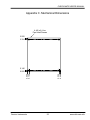
APPENDIX C. MECHANICAL DIMENSIONS
22
Overton Instruments
3
www.chk-mate.info
CHECK-MATE USER’S MANUAL
1. Introduction
1.1 Overview
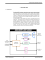
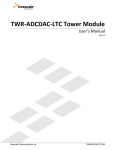
The Check-MATE has all the primary features you expect in a general purpose
data acquisition board, but for a fraction of the cost. It offers 8 single or 4 differential analog inputs with 12-bit resolution (and a sampling rate of 100ksps).
Each of the analog inputs can be programmed for unipolar or bipolar operation.
Likewise, the analog output uses a 12-bit DAC (and operates in unipolar or bipolar modes). In addition, there are 8 digital input/output lines (which are independently programmable).
The Check-MATE is made available in two versions, a standard model or with a
USB option. The standard model is designed for embedded applications and
provides a simple Oi-BUS interface for control by a external microcontroller.
With the USB option, many test solutions can be quickly built by connecting the
Check-MATE to a PC laptop or desktop, and then running our GUI software.
No external power source is required, since power is supplied through the USB
interface. Any either case, easy access to the hardware is made available
through a convenient collection of screw terminal connectors.
.
INPUT
MUX
CHECKCHECK - MATE BLOCK DIAGRAM
12-BIT A/D
CONVERTER
+5V
DC/DC
ANALOG
INPUTS
8 SE / 4 DIFF
+15V
-15V
USB
INTERFACE
(OPTIONAL)
CONTROL
INTERFACE
12-BIT D/A
CONVERTER
ANALOG
OUTPUT
DIGITAL I/O
EMBEDDED
INTERFACE
Overton Instruments
4
DIGITAL I/O
8-BITS
www.chk-mate.info
CHECK-MATE USER’S MANUAL
1.2 Highlights
BENEFITS
• A flexible, low-cost alternative to expensive PC-based
DAQ cards
• Supports a wide-array of
mix-signal test applications
• Great for embedded solutions - place inside mechanical test fixtures, instrument
boxes or rack-mount enclosures
APPLICATIONS
• Burn-In
FEATURES
• 8 SE /4 DIFF Analog Input
Channels, 12-bit Resolution,
100ksps sample rate
• Engineering
• Depot Repair
• Production Test
• QA/QC Quality Control
• OEM Test Instruments
• 1-Channel, Digital-to-Analog
converter, 12-bit Resolution,
Unipolar/Bipolar modes
• 8 Digital Input/Output Bits,
Independently programmable
• USB or embedded control
interface
• Low Cost
• Compact size, a 2.5” x 2.5”
PCB, with four #4 mounting
holes in each corner (spacers
and hardware included)
Overton Instruments
5
www.chk-mate.info
CHECK-MATE USER’S MANUAL
1.3 Specifications
Analog Inputs
Number of inputs
8 SE / 4 DIFF, programmable
Input Ranges
0-5V, 0-10V, ±5V, ±10V
Resolution / Sample
Rate
12-bit / 100ksps
Nonlinearity
±1LSB, no missing codes
Analog Output
Resolution
12-bit
Range
0-10V, ±10V
Current
±5mA max
Settling Time
4uS max to ±1/2 LSB
Relative Accuracy
±1 LSB
Digital I/O
Number of lines
8 bits, bidirectional
Logic Levels
TTL, ±25mA (source/sink)
Input Control
Embedded
Oi-Bus interface
USB Interface
Optional USB module
General
Overton Instruments
Power Supply
+5VDC±10%@3mA
Operating Temp
0-50ºC
Dimensions
2.5” x 2.5”
6
www.chk-mate.info
CHECK-MATE USER’S MANUAL
2. I/O Description
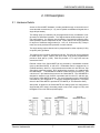
2.1 Hardware Details
Access to Check-MATE hardware is made possible through a convenient set of
screw terminal connections (J2 - J5), and J6 (which consolidates all signals into a
single 40-pin header).
The analog inputs (or channels) can be programmed for any combination of single-ended or differential operation. The diagram below shows examples of various configurations. You will also note the polarity of connections related to differential operation can be transposed as well. Each channel can be programmed
for anyone of 4 different range modes (i.e., 0-5V, ±5, 0-10V and ±10V). Keep in
mind, the circuit provides ±25V protection on each channel.
The single analog output channel can be programmed for either unipolar (0-10V),
or bipolar (±10V) operation.
The digital circuit includes 8 independent I/O bits. Each bit can be programmed
for either input or output. While in the input mode, a bit can be programmed to
provide a weak pull-up (~10K). Each bit provides a TTL logic level and can
source/sink 25mA.
External control of the Check-MATE can be provided by a embedded controller
(such as the Micro-MATE), or with a PC. Embedded control is supported by J1
(Oi-BUS interface), which is a 10-pin header that includes a 3-wire SPI-bus, chip
select logic, power and ground. In PC applications, connector J1 is replaced with
the USB--MATE. The USB-MATE contains a USB connector (for the PC), and
a dual set of 7-pin headers that mount to the Check-MATE. The USB-MATE is
designed to interpret a set of ASCII commands sent from the PC, and then perform various Check-MATE functions. For more information on the Check-MATE
command set, go to Appendix A. To support embedded applications, a complete
driver for the Check-MATE is provided in TES-MATE (or Test Executive Suite).
After power is applied to the Check-MATE, the analog inputs are configured for
single-ended (0-5V range), the analog output is set to zero (range is 0-10V), and
the digital I/O circuit is cleared (all bits inputs).
Overton Instruments
7
www.chk-mate.info
CHECK-MATE USER’S MANUAL
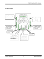
2.2 Board Layout
J5 - 5 Pin Terminal
Provides access to SPIbus control signals.
J4 - 2 Pin Terminal
- DAC output Pin 1, (+)
Pin 2, (-)
J4 - 9 Pin Terminal
Provides access to
the analog input.
J2 - 10 Pin Terminal
Provides access to
the digital I/O.
Convenient GND
test point.
LED to indicate
active circuit.
USB Interface
Connectors USB-1 and
USB-2 replaces J1,
and allows connection
to the USB-MATE.
Overton Instruments
J1 - 10 Pin Interface
Provides access for
remote control via an
Embedded controller.
8
www.chk-mate.info
CHECK-MATE USER’S MANUAL
J2
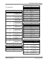
2.3 Connections
J1
Pin
1
2
3
4
5
6
7
Name
Dir.
VCC
SCLK
Part of a 3-wire SPI-Bus,
SCLK synchronizes the
serial data transfer for the
DIN and DOUT signals.
ADC_CS\
I
DIN
I
DAC_CS\
DOUT
I
O
DIO_CS\
8
UNI/BIP\
9
DGND
10
BUSY\
I
I
Name
Dir.
Description
1
VCC
2
DIO-0
I/O
Bit 0
3
DIO-1
I/O
Bit 1
4
DIO-2
I/O
Bit 2
5
DIO-3
I/O
Bit 3
6
DIO-4
I/O
Bit 4
7
DIO-5
I/O
Bit 5
8
DIO-6
I/O
Bit 6
9
DIO-7
I/O
Bit 7
10
DGND
+5V Power
Description
A regulated +5Vdc input .
Current should be limited
to roughly 100mA.
I
Pin
A TTL active-low “input’
signal that provides a
chip-select for the ADC.
Part of a 3-wire SPI-Bus,
DIN provides input command and control data for
the, ADC, DAC and DIO
circuits.
Digital Ground
J4
Pin
Name
Dir.
Description
A TTL active-low “input’
signal that provides a
chip-select for the DAC..
1
AI-1
I
Input CH 1
2
AI-2
I
Input CH 2
Part of a 3-wire SPI-Bus,
DOUT provides output
data from the ADC and
DIO circuits.
3
AI-3
I
Input CH 3
4
AI-4
I
Input CH 4
5
AI-5
I
Input CH 5
A TTL active-low “input’
signal that provides a
chip-select for the DIO.
6
AI-6
I
Input CH 6
7
AI-7
I
Input CH 7
A TTL active-low “input’
signal that determines
unipolar (1), bipolar (0)
for the DAC.
8
AI-8
I
Input CH 8
9
AGND
Analog Ground
Digital Ground
O
A TTL active-low “output’
signal that indicates the
ADC is busy converting a
measurement.
J3
Pin
Name
Dir.
1
DAC-OUT
O
2
AGND
Overton Instruments
J5
Pin
Name
Dir.
1
VCC
2
SCLK
I
Part of a 3-wire SPI-Bus.
Use with DIO for possible
external control
7
DIN
I
Part of a 3-wire SPI-Bus.
Use with DIO for possible
external control
9
DOUT
O
Part of a 3-wire SPI-Bus.
Use with DIO for possible
external control
10
DGND
+5V Power
Description
Voltage Output
Analog Ground
9
Description
Digital Ground
www.chk-mate.info
CHECK-MATE USER’S MANUAL
2.4 J6 Consolidated
J6
Overton Instruments
Pin
Name
Dir.
Description
1
VCC
2
DIO-0
I/O
Bit 0
3
DIO-1
I/O
Bit 1
4
DIO-2
I/O
Bit 2
5
DIO-3
I/O
Bit 3
6
DIO-4
I/O
Bit 4
7
DIO-5
I/O
Bit 5
8
DIO-6
I/O
Bit 6
9
DIO-7
I/O
Bit 7
10
DGND
11
DAC-OUT
12
AGND
13
AI-1
I
Input CH 1
14
AI-2
I
Input CH 2
15
AI-3
I
Input CH 3
16
AI-4
I
Input CH 4
17
AI-5
I
Input CH 5
18
AI-6
I
Input CH 6
19
AI-7
I
Input CH 7
20
AI-8
I
Input CH 8
+5V Power
Digital Ground
O
Voltage Output
Analog Ground
10
www.chk-mate.info
CHECK-MATE USER’S MANUAL
3. Operation
3.1 Embedded Control
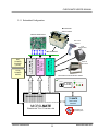
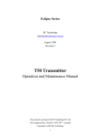
In section 3.1.1 (on the next page), the Check-MATE is shown integrated with
other ETS Series components that collectively form a complete Embedded Test
Solution. The diagram shows the Check-MATE being driven by the Micro-MATE.
The Micro-MATE is a low-cost “Embedded Test Controller”, which stores a special program that is designed to exercise the device-under-test and generate Go/
No-Go test results. The Micro-MATE also provides a sizable breadboard area to
support the development of custom circuits. Adjacent to the breadboard area is
a series of wire-wrap pins that comprise a goodly amount of general purpose
Digital I/O. The schematic below shows the wire-wrap connections which create
the interface between the Micro-MATE and the Check-MATE (J1, 10-pin header
connector).
Actually the Check-MATE can be easily driven by most microcontrollers
(including an ARM, AVR, PIC or even a STAMP). When developing an interface
for the Check-MATE, it is recommended the designer start-by reviewing the interface requirements as outlined in the J1 Table (which is provided in the I/O Description section). The next step is to review the Check-MATE schematic, which
is provided in Appendix B. What could be the most challenging aspect of the
design effort is controlling the SPI-bus devices. The Check-MATE contains 3
SPI-bus devices which include an ADC, DAC and DIO circuits. The ADC is a 12bit 8-channel data acquisition chip from Linear Technology (part number
LTC1857). The DAC is a 12-bit digit-to-analog converter from Maxim (part number MAX5312). The DIO is an 8-bit device from MicroCHIP (part number
MCP230S08). Details for specific device performance and SPI-bus operation
can be found in their respective data sheets. Go to the manufacturers website to
download said documents.
Overton Instruments
11
www.chk-mate.info
CHECK-MATE USER’S MANUAL
3.1.1 Embedded Configuration
Mechanical
Test Fixture
Device-Under-Test
Bar-Code
Scanner
Test
Results Ticket
B E D - O F - N AI L S
CO
4-Port RS232 Serial
Communications Module
COM4-MATE
Multifunction
DAQ Module
12Vdc
POWER
SUPPY
CHECK-MATE
DUT-MATE
DUT
POWER
SOURCE
(+9Vdc)
Power Control Module
COM-1
M
-2
CO
COM
M-
External
Instrument
3
-4
COM4-MATE Interface
Oi-Bus Interface
Oi-Bus Interface
Universal Test Control Panel
POWER
START
TEST
MODE/SELECT
RUN
99
LCD
PASS
FAIL
STOP
BREAD-BOARD AREA
TCI-MATE
Test Control
Interface
MICRO-MATE
E MBEDDED T EST C ONTROLLER
Overton Instruments
12
Automated Test,
No PC Required
www.chk-mate.info
CHECK-MATE USER’S MANUAL
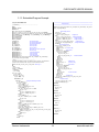
3.1.2 Embedded Programming
To build-on the PCB board test example (shown in section 3.1.1), we have constructed a demo program using BASCOM. BASCOM is a BASIC language compiler that includes a powerful Windows IDE (Integrated Development Environment), and a full suite of “QuickBASIC” like commands and statements. The
demo program (which is outlined in section 3.2.3), illustrates the ease of controlling the Check-MATE via the Micro-MATE microcontroller.
The program starts by initialing the Micro-MATE for proper operation. You will
note that the BASCOM software provides excellent bit-manipulation capabilities,
as evident by the use of the ALIAS statement. The Micro-MATE (P1.7 & P1.6
port bits) are assigned unique label names (i.e., SCLK, DOUT), which are used
to support various Check-MATE functions. In the “Main” program section, the
Micro-MATE receives “high level” serial commands from a host PC, parses them
and then executes accordingly. When (for example), the “CK_RC?4S01” command is entered, the program selects analog channel number 4 (’S’ for singleended, ‘0’ for +/- polarity, ‘1’ for 5V range) and returns the results in a 3 character
hexadecimal “ASCII” string.
Independent of the microcontroller hardware or programming language you
choose, the program sequence described above will likely resemble the way you
implement your Check-MATE application. For this reason, we suggest that you
go to our website and download the “Check-MATE.zip” file. In the Documents
folder will contain more extensive examples of routines to control the CheckMATE.
Overton Instruments
13
www.chk-mate.info
CHECK-MATE USER’S MANUAL
3.1.3 Embedded Program Example
' Program: CHECK-MATE Demo
'
---[ Initialization ]---------------------------------------------------------'
$large
$romstart = &H2000
$default Xram
‘===================================================================
'
ADC Subroutine
'===================================================================
Sub Chk_rd_adc(chk_val As Word , Chk_ch As Byte , Chk_mode As Byte , Chk_pol As
Byte , Chk_range As Byte)
' Select analog channel
Chk_long = 0
If Chk_mode = 1 Then
Chk_ch = Chk_ch_buf(chk_ch)
' configure SE
Else
Chk_ch = Chk_ch_buf_d(chk_ch) ' configure Differential
If Chk_pol = 0 Then Chk_num.6 = 0
' configure Polarity +/' configure Polarity -/+
If Chk_pol = 1 Then Chk_num.6 = 1
End If
Chk_range = Chk_range_buf(chk_range)
' configure Range
Chk_cntl_byte = Chk_range Or Chk_ch
' configure Control Byte
Reset Sclk
' take X measurements
For Chk_loop = 0 To Chk_m_cnts
Chk_word = 0
While Adc_busy = 0 ' check busy flag
Wend
' Select device
Reset Adc_cs
For Chk_cnt = 15 Downto 0
If Chk_cnt >= 8 Then
Chk_num = Chk_cnt - 8
Dout = Chk_cntl_byte.chk_num
' transmit serial data
End If
Set Sclk
Reset Sclk
Next Chk_cnt
Set Adc_cs
' disable device
While Adc_busy = 0
' check busy flag
Wend
Reset Adc_cs
' Select device
For Chk_cnt = 15 Downto 0
If Chk_cnt >= 8 Then
Chk_num = Chk_cnt - 8
Dout = Chk_cntl_byte.chk_num
End If
Set Sclk
Chk_word = Din
' receive serial data
Reset Sclk
Next Chk_cnt
Set Adc_cs
' disable device
If Chk_loop > 0 Then Chk_long = Chk_long + Chk_word
Next Chk_loop
' compute average
Chk_long = Chk_long / Chk_m_cnts
Chk_val = Loww(chk_long)
End Sub
Dim A_word, Chk_word, Chk_val As Word
Dim A_num, A_byte, A_cnt, A_ch, Chk_cntl_byte, Chk_loop, Chk_m_cnts As Byte
Dim Chk_ch, Chk_range, Chk_pol, Chk_mode, Chk_num, Chk_cnt, Chk_cntl_byte As Byte
Dim S As String * 10, A_resp AS String * 10, A_str AS String * 10, A_char AS String*1
Dim Chk_long as Long
Dim True As Const 1
Dim False As Const 0
Dim Err_trap As Bit
Sclk Alias P1.6
Dout Alias P1.7
Din Alias P1.5
Adc_cs Alias P0.0
Dac_cs Alias P0.1
Dio_cs Alias P0.2
Dac_mode Alias P0.3
Adc_busy Alias P0.4
‘ SPI-bus serial clock
‘ SPI-bus serial data output
‘ SPI-bus serial data input
‘ ADC chip select
‘ DAC chip select
‘ DIO chip select
‘ DAC mode, (1) unipolar, (0) bipolar
‘ADC busy flag
Declare Sub Print_ic
‘ print invalid command
Declare Sub Print_orr
‘ print out-of-range
Declare Sub Print_ur
‘ print under range
Declare Sub Print_ok
‘ print command is OK
Declare Sub Chk_rd_adc(chk_val As Word , Chk_ch As Byte , Chk_mode As Byte ,
Chk_pol As Byte , Chk_range As Byte)
---[ Main ]---------------------------------------------------------' In the Main the Operator or Host, is prompted to enter a command. The command is
‘ parsed and then executed if valid. Only one command example is shown.
Set Sclk, Dout, Adc_cs, Dac_cs, Dio_cs, Dac_mode ‘ Set to logic ‘1’
Do
Print
Err_trap = False
Input "-> " , S Noecho
S = Ucase(s)
A_num = Len(s)
If A_num > 0 Then
A_resp = Left(s , 3)
If A_resp = "CK_" Then
A_resp = Mid(s , 4 , 2)
Select Case A_resp
Case "RC":
' Configure & Read single channel
A_char = Mid(s , 6 , 1)
If A_char = "?" Then
A_char = Mid(s , 7 , 1)
Chk_ch = Val(a_char)
If Chk_ch > 8 Then Err_trap = True
A_char = Mid(s , 8 , 1)
If A_char <> "D" And A_char <> "S" Then
Err_trap = True
Else
If A_char = "D" Then Chk_mode = 0
If A_char = "S" Then Chk_mode = 1
End If
A_char = Mid(s , 9 , 1)
If A_char <> "0" And A_char <> "1" Then
Err_trap = True
Else
If A_char = "0" Then Chk_pol = 0
If A_char = "1" Then Chk_pol = 1
End If
If Chk_ch > 4 And Chk_mode = 0 Then Err_trap = True
A_char = Mid(s , 10 , 1)
Chk_range = Val(a_char)
If Chk_range < 1 Or Chk_range > 4 Then Err_trap = True
If Err_trap = False Then
Call Chk_rd_adc(chk_val , Chk_ch , Chk_mode , Chk_pol , Chk_range)
Printhex "<" ; Chk_val ; ">"
Else
Call Print_oor
End If
Else
Call Print_ic
End If
Overton Instruments
Sub Print_ic
Err_trap = True
Print "><"
End Sub
Sub Print_oor
Err_trap = True
Print ">>"
End Sub
Sub Print_ok
Print "<>"
End Sub
Sub Print_ur
Err_trap = True
Print "<<"
End Sub
14
www.chk-mate.info
CHECK-MATE USER’S MANUAL
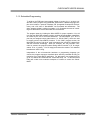
3.2 PC Control
For those more comfortable building traditional PC-based “Automated Test
Equipment” (ATE), the Check-MATE offers many features that are well suited for
that environment as well.
Controlling the Check-MATE from a PC, requires that it be equipped with an optional USB-MATE module. The USB-MATE module contains a USB bridge-chip
and a PIC microcontroller. On the PC side, the USB bridge-chip receives a special set of serial commands. On the Check-MATE side, the PIC controller processes the serial commands and then drives the Check-MATE hardware accordingly. In order to be recognized by the PC, the USB-MATE module requires a set
of Windows’ drivers be installed. To do so, go to “www.Check-MATE.info”, click
“Download”, select the “OI VCP Interface” file and follow the prompts. The letters
VCP stands for “Virtual COM Port”, and is a method by-which the USB interface
can appear to the PC as a standard serial COM port. With the drivers installed
and the USB-MATE connected to the PC, go to the Device Manager (click on
Ports) and verify “OI Serial Interface (COM#)” is included.
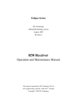
The diagram below provides a basic illustration of a PC-driven configuration. As
shown, the Check-MATE is used to stimulate a hybrid module in a test & measurement application. The hybrid module is a mix-signal device that requires Analog I/O, as well as Digital I/O to function properly.
Analog Out
Digital I/O
Analog In
PC Control
HyperTerminal
Control
GUI
Add a USB Hub/s to
drive multiple CheckMATEs and/or other
OI instruments
Overton Instruments
Typical Hybrid Circuit Module
15
www.chk-mate.info
CHECK-MATE USER’S MANUAL
3.2.1 PC Programming
The starting point for developing code to control the Check-MATE, begins with
acquainting yourself with its Serial Command Set. The serial commands are a
sequence of ASCII characters that originate from the PC and are designed to
instruct the Check-MATE to perform specific functions. The complete serial command set is detailed in Appendix A. There are two ways to exercise the serial
commands, (1) using HyperTerminal or (2), run our Virtual Instrument Panel software (Control GUI).
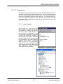
3.2.1.1 HyperTerminal
HyperTerminal is a serial communications program that comes with the Windows OS and is located in the Accessories folder. Use the USB cable to connect the PC to the Check-MATE. Run
HyperTerminal and configure the settings
for 19200 bps, 8 data bits, no parity, 1
stop bit and no flow control. Select the
COM port based on the available COM
port as indicated in the Device Manager
(example shown below).
Press the
‘Enter’ key and the ‘’ prompt should
appear on the screen (as demonstrated
in the example on the right). Refer to the
table in Appendix A, to begin to experiment with the serial commands.
Overton Instruments
16
CK_ID?
<Check_MATE vx.x>
CK_RC?4S01
<000>
www.chk-mate.info
CHECK-MATE USER’S MANUAL
3.2.1.2 Virtual Instrument Panel
The Virtual Instrument Panel (or Control GUI), removes the hassle of “manually “
typing ASCII commands and provides the User a more efficient method to interact and control the Check-MATE. Download the panel from our website at
www.check-mate.com, click on downloads and select “Check-Matexxx.exe”.
First Step: The User must
select a COM Port. Refer to
the Device Manage to identify an available COM port.
Second Step: Push the Initialize
button. This will cause the module
to initialize itself and attempt to
establish a communications link.
Third Step: After initializing, the module
should send back a unique ID code. If no
response has occurred within 10 seconds,
the program will time-out , and generate a
No Response message.
This ‘Range’ function selects
(1 of 4) specific analog input
modes.
Each ‘Analog
Input CH’ can be set to a
different range setting.
The ‘Volt Meter’, displays a
voltage measurement
based the current analog
channel and range setting.
The ‘Analog Input CH’ function selects an individual
analog channel (1 to 8).
The ‘ACQUIRE’ function
updates the analog configuration settings, and
displays a measurement
every 100msec.
This ‘Range’ function selects
either Unipolar or Bipolar
operation.
The ‘Output Voltage’ function updates the analog
configuration settings, and
displays a measurement
every 100msec.
The ‘Enable’ function updates
the analog output settings.
This function panel allows
the User to control the DIO
circuit. The top section
provides a tool for setting
the ‘bit’ direction. A blankcircle (indicates input), and
a dot-circle (indicates output). The middle section
includes a set of eight LED’s
(which indicate input status).
The bottom section includes
eight push-button switches
(which allow the setting of
output bits). When the
switch is the out position
(that represents a logic ’0’).
When the switch is in the in
position (that represents a
logic ‘1’).
The ‘DIO Trigger’ function
updates the DIO configuration settings.
The ‘STATUS’ message box
summarizes results of the
serial commands.
Overton Instruments
17
www.chk-mate.info
CHECK-MATE USER’S MANUAL
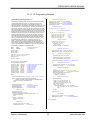
3.2.1.3 PC Programming Example
// Check-MATE programming example in ‘C’
//
// The following program provides a Go/No Go test sequence for testing
// a hypothetical electronic module. The electronic module is a mix// signal hybrid device that contains 8 programmable amplifiers. The
// electronic module is controlled by a Check-MATE via the DIO lines. DIO
// bits 0-3 (select one of 8 DUT amplifiers). DIO bits 4 & 5 (selects the
// gain range). DIO bit 6 is active-low (provides a DUT chip-select). DIO
// bit 7 is active-high input (which indicates the DUT is ready). The outputs
// for the DUT amplifiers are connected to the inputs of the Check-MATE
// analog channels. The objective for the program is to verify each of the 8
// amplifiers will perform properly at each gain setting and over a varying
// range of input voltage levels. During the test sequence, the program
// first selects both the DUT amplifier and the Check-MATE ADC chan// nel. Then the DUT gain is selected and the Check-MATE updates the
// DUT by writing the control byte (which asserts the chip-select). The
// Check-MATE then reads DIO-bit-7 to determine if the DUT is
// ready. Once the DUT is ready, the Check-MATE will stimulate the
// DUT amplifier input by supplying a voltage from the DAC output. To
// verify the DUT amplifier, the program reads the Check-MATE analog
// channel and determines the PASS/FAIL results. The Check-MATE is
// controlled by a remote PC, via a USB interface.
#define
#define
MSWIN
MSWINDLL
// Set DIO direction & weak pull-up
sprintf (send_data, "%s%s\r", set_dio_dir, "10000000");
PutString(port,send_data);
// send CK_PD10000000
sprintf (send_data, "%s%s\r", set_dio_pullup, "10000000");
PutString(port,send_data);
// send CK_PU10000000
// Execute test sequence
for (dut_ch = 0; dut_ch >= 7; dut_ch++) {
// exercise DUT gain performance
for (gain_sel = 0; >= 3; gain_sel++) {
if (gain_sel == 0) dut_gain = 4095;
if (gain_sel == 1) dut_gain = 409;
if (gain_sel == 2) dut_gain = 40;
if (gain_sel == 3) dut_gain = 4;
// x1 range
// x10
// x100
// x1000
// build dio control byte
a_byte = dut_ch + (gain_sel + 8)
for ( idx = 0; idx <= 7; idx++ ) {
dio_bit[idx] = a_byte % 2;
a_byte = a_byte / 2;
sprintf (dio_byte[idx], "%d", dio_bit[idx]);
}
// serial comm libraries from
// www.wcscnet.com
// Select DUT, gain & amp ch
#include <comm.h>
#include <stdlib.h>
#include <stddio.h>
sprintf (send_data, "%s%s\r", set_dio_port, dio_byte);
PutString(port,send_data); // send CK_PBxxxxxxxx
do {
int stat, port=0, a_byte = 0, a_cnt = 0, int idx = 0;
int dut_ch = 0, dut_gain =0, gain_sel = 0;
int dio_bit[10] = 0;
// Get DIO input - check DUT ready
sprintf (send_data, "%s\r", get_dio_port);
PutString(port,send_data); // send CK_PB?
GetString(port,sizeof(read_data),read_data);
long value = 0, limit = 0;
} while (atoi (read_data[1])); // loop while msb = '0', DUT not ready
char dio_byte[10], dir_byte[10], results[64];
char send_data[64], read_data[64];
char get_adc_volts[]
char set_dac_range[]
char set_dac_out[]
char set_dio_dir[]
char set_dio_pullup[]
char set_dio_port[]
char get_dio_port[]
char get_device_id[]
char master_clear[]
= "CK_RC?";
= "CK_DM";
= "CK_SA";
= "CK_PD";
= "CK_PU";
= "CK_PB";
= "CK_PB?";
= "CK_ID?";
= "CK_MC";
do {
// configure & read a single ADC channel
// set DAC voltage range
// set DAC output voltage
// set DIO port direction
// set DIO port pull-up
// set DIO port write
// get DIO port
// get module ID
// master clear
// Get check-mate ADC input
A_ch++;
sprintf (send_data, "%s%d%s\r", get_adc_ch, A_ch, “S04” );
// send ‘CK_RC?’ command
PutString(port,send_data);
GetString(port,sizeof(read_data),read_data);
for ( idx = 1; idx <= 3; idx++ ) {
results[idx] = read_data[idx];
}
// determine pass/fail results
main()
{
port=OpenComPort(1,256,64); // Open COM 1, rx_buff = 256 bytes, tx_buff = 64
if ((stat = SetPortCharacteristics(port,BAUD19200,PAR_EVEN,
LENGTH_8,STOPBIT_1,PROT_NONNON)) != RS232ERR_NONE) {
printf("Error #%d setting characteristics\n",stat);
exit(1);
}
// 1 msec ticks
CdrvSetTimerResolution(port,1);
SetTimeout(port,2000);
// 2000 ticks = 2 sec time-out
FlushReceiveBuffer(port);
// clear receiver buffer
FlushTransmitBuffer(port);
// clear transmit buffer
Value = atoi(results);
if (gain_sel == 1) dut_gain = dut_gain * 10;
if (gain_sel == 2) dut_gain = dut_gain * 100;
if (gain_sel == 3) dut_gain = dut_gain * 1000;
limit = asb(value - dut_gain);
if (limit > (0.001 * 4096)) {
printf ("Test Failed - ADC Ch:", "%d", " Gain Range:",
"%d", " Gain Value", "%d", dut_ch, gain_sel, dut_gain);
exit(1);
{
dut_gain--;
// Get device prompt
sprintf (send_data, "%s\r", "");
PutString(port,send_data); // send CR
if ((resp_len = GetString(port,sizeof(read_data),read_data)) == 0); {
printf("Time-out error\n");
exit(1);
}
if (strcmp("-> ", read_data)) {
printf("Incorrect promt\n");
exit(1);
}
// Master Clear
// Set check-mate DAC output
sprintf (send_data, "%s%04d\r", set_dac_out, dut_gain);
PutString(port,send_data);
// send CK_SAnnnn
} while (dut_gain != 0);
// De-select DUT
sprintf (send_data, "%s%s\r", set_dio_port, "00000000");
PutString(port,send_data);
// send CK_PB00000000
}
}
printf ("Test Passed");
}
sprintf (send_data, "%s\r", master_clear);
PutString(port,send_data);
// send CK_MC
Overton Instruments
18
www.chk-mate.info
CHECK-MATE USER’S MANUAL
Appendix A. Serial Command Set
To facilitate remote control for the Check-MATE, a USB interface is required. When connected to a host
PC, the USB connection appears as a “Virtual Com Port”, which establishes a serial data communications link between the two. The default protocol is 19200 baud rate, no parity, 1 stop bit and no flow control. The Check-MATE will respond to a unique set of ASCII serial data commands (listed below). The
first three bytes of the command string starts with the prefix ‘CK_’, followed by a code that represents
the actual command. All commands are upper case sensitive and are terminated with a carriage-return.
If the command is valid, the Check-MATE will return either a ‘<>’, or a bracketed result (i.e. ‘<0F4>’. If
the Check-MATE receives a carriage-return or line-feed alone (without a command), then a ‘
’ is returned (this response is a “prompt” to signal the Check-MATE is ready). If the Check-MATE detects an
incorrect command then one of three error symbols will be generated, (1) invalid command then a ‘><’ is
returned, (2) a command that is out-of-limits then a ‘>>’ is returned, and (3) a command that prematurely
times-out then a ‘<<‘ is returned. In some cases the error symbol will include a bracketed result (i.e.
‘>1<’), which defines a specific error code.
Command
Function
Response
Description
CK_BRn
Set baud rate code
<n>
Select one of 4 different baud rates by changing -n-code. 0 = 1200, 1 = 2400, 2 = 9600 & 3
= 19200. Baud will remain set. Default code
is 3 (19200).
CK_BR?
Get baud rate code
<n>
Get current baud rate code (-n- is the return
code 0 to 3).
CK_ID?
Get module ID
CK_MR
Maser Reset
CK_SScr
CK_SDcpr
Set single-ended
configuration
Set differential
configuration
Overton Instruments
<CHECK-MATE vx.x> Get current identification and version number.
<>
Reset & initialize the module
<>
Set single-ended channel configuration.
c = ADC channel number (1 to 8)
r = ADC range (1 = +5V, 2 = ±5V, 3 = 10V, 4 =
±10V)
If c=0, then all channels are set to ‘r’ (same
range)
<>
Set differential channel configuration.
c = ADC channel number (1 to 4)
p = ADC polarity (0 = +, 1 = -)
r = ADC range (1 = +5V, 2 = ±5V, 3 = 10V, 4 =
±10V)
If c=0, then all channels are set to ‘p’ and
‘r’ (same polarity and range)
19
www.chk-mate.info
CHECK-MATE USER’S MANUAL
Appendix A. Serial Command Set cont.
Command
CK_RC?cmprf
Function
Configure channel
and get voltage
measurement
Response
Description
<n>
Configure and read a specific ADC channel.
c = ADC channel number (1 to 8 SE or 1 to 4
Diff)
m = ADC mode (“S” = Single-Ended, “D” =
Differential)
p = ADC polarity (0 = +/-, 1 = -/+)
r = ADC range (1 = +5V, 2 = ±5V, 3 = 10V, 4 =
±10V)
f = Data format (“D” = Decimal, “H” = Hexadecimal
The voltage measurement contains a series of
ASCII bytes representing a 12-bit value which
is expressed in counts (0-4095 or 000-FFF).
<CH1mpr=nnnn,
CH2mpr=nnnn,..,
CH8mpr=nnnn>
Auto scan all ADC channels and return readings based-on presets from channel configuration commands ‘CK_SS’ and ‘CK_SD’. The
measured data is returned in one of two
forms, Basic or Extended. In Extended each
channel is identified (including the mode, polarity and range codes). The voltage measurements are a series of ASCII bytes representing a 12-bit value that is expressed in
counts (0-4095 decimal or 000-FFF hex). A
comma is used to separate each channel
reading. In Basic mode, the measured data is
provided alone. When n=0 (Basic mode is
active), and n=1 (Extended mode is active).
When f=“D” (decimal data),
f=“H” (hexadecimal data).
CK_AS?nf
Scan all channels
and return voltage
measurements
CK_MSnnn
Set ADC measurement sample count
<>
Analog inputs can be averaged with a measurement sample count. The sample count
value -nnn-, must be a 3 byte ASCII decimal
from “000” to “255”.
CK_MS?
Get ADC measurement sample count
<n>
Get the current ADC sample count .
CK_SAnnnn
Set voltage output
<>
Set the DAC output voltage level. The DAC
value -nnnn-, must be a 4 byte ASCII decimal
number from “0000” to “4095”. In bipolar
mode, “0000” = -10Vdc.
CK_SA?
Get voltage output
<n>
Get the current DAC output voltage.
CK_DMn
Set DAC mode
<>
Set the DAC range mode (-n- is 1 = 0-10Vdc
and 0 = ±10Vdc).
CK_DM?
Get DAC mode
<n>
Get the current DAC range mode.
Overton Instruments
20
www.chk-mate.info
CHECK-MATE USER’S MANUAL
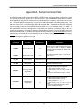
Appendix A. Serial Command Set cont.
Command
Function
Response
Description
Set (or write) the DIO port direction. The direction byte is represented by eight ASCII
bytes starting with the most-significant-bit (-bleft most) to the least-significant-bit (-b- right
most). A logic ‘1’ is input and ‘0’ is output.
CK_PDbbbbbbbb
Set DIO direction
<>
CK_PD?
Get DIO direction
<bbbbbbbb>
Set (or write) pull-ups on the DIO port inputs.
The pull-up byte is represented by eight ASCII
bytes starting with the most-significant-bit (-bleft most) to the least-significant-bit (-b- right
most). A logic ‘1’ is active and ‘0’ is not.
CK_PUbbbbbbbb
Set weak pull-ups
<>
CK_PU?
Get weak pull-ups
<bbbbbbbb>
Get (or read) the current DIO port pull-up
status.
Set (or write) the DIO port output bits. Depending on the condition of the direction byte,
the output bits are represented by eight ASCII
bytes starting with the most-significant-bit (-bleft most) to the least-significant-bit (-b- right
most). The -b- bit is a logic ‘1’ or ‘0’.
CK_PBbbbbbbbb
Set DIO port
<>
CK_PB?
Get DIO port
<bbbbbbbb>
Overton Instruments
Get (or read) the current DIO port direction
setting.
21
Get (or read) the current DIO port status.
www.chk-mate.info
CHECK-MATE USER’S MANUAL
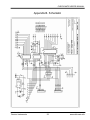
Appendix B. Schematic
Overton Instruments
22
www.chk-mate.info
CHECK-MATE USER’S MANUAL
Appendix C. Mechanical Dimensions
4-40 (x4), Hex
Pan Head Screws
2.500
2.354
Overton Instruments
2.354
2.500
0.000
0.146
0.146
0.000
23
www.chk-mate.info