1
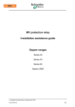
63230-216-239B1
05/2007
LaVergne, TN, USA
Instruction Bulletin
Sepam™ Series 20 & 40 Relays
Quick Start Guide
Retain for future use.
Introduction
Sepam™ Series 20 and Series 40 protective relays are designed for
protection applications on medium-voltage distribution networks.
Sepam Series 20 Relays
Sepam Series 20 relays are designed for simple applications and include:
•
•
•
•
Sepam Series 40 Relays
Eight Relay Outputs
One Communication Port
Eight Temperature Sensor Inputs
Sepam Series 40 relays are designed for demanding applications and include:
•
•
•
•
•
Storage
10 Logic Inputs
10 Logic Inputs
Eight Relay Outputs
One Logic Equation Editor
One Communication Port
16 Temperature Sensor Inputs
Store the Sepam relay in its original packaging in a closed, sheltered
location. Check the storage environment annually for the following
recommended conditions:
•
•
Commissioning
Ambient temperature of -13° to +160° F (or -25° to +70° C)
Non-condensing humidity ≤ 90%
Once installed, energize the Sepam relay as quickly as possible, especially
in damp locations (condensing humidity ≥ 90%).
DANGER
HAZARD OF ELECTRIC SHOCK, BURN OR
ARC FLASH
• Turn off power supplying the relay and
equipment in which it is installed before
working on it.
• Always use a proprely rated voltage-sensing
device to confim that power is off.
• Replace all devices, doors, and
barriers/covers before energizing
this equipment.
For more information, please refer to:
Failure to follow these instructions will
result in death or serious injury.
•
•
Sepam Series 20 User’s Manual - 63203-216-208C1
Sepam Series 40 User’s Manual - 63203-216-219B1
1
Sepam™ Series 20 & 40 Relays
Identification
63230-216-239B1
05/2007
Each Sepam relay comes in a single package that contains the base unit
and its connector. Optional accessories, such as modules, the current or
voltage input connector, or cables come in separate packages.
To identify a Sepam relay, check the two labels on the right side panel of the
base unit that describe the firmware and hardware features of the product.
Figure 1:
Hardware Equipment Label
User Machine Interface Model
Power Supply
Sepam Code
Figure 2:
Firmware Equipment Label
Application Type
Operating Language
Sepam Code
Components
A. Optional Input/Output Modules
(MES108 or MES114)
A
1
B. MES108 or MES114 Module Connectors
2
C. MES114 Module Connector
D. MES108 or MES114 Module Connectors
1. Base Unit
B
3
2. Input Voltage Connector (Series 40 only):
Screw-Type Connector (CCA626), or
Ring Lug Connector (CCA627)
3. 1/5 A CT Input Current Connector (CCA630),
or LPCT Input Current Connector (CCA670),
or Voltage Input Connector (CCT640,
Series 20 only)
4. Base Unit Connector:
4
C
D
— Power Supply
— Output Relay
— Input CSH30 / 120 / 200 or ACE990
— Screw-Type Connector (CCA620), or
Ring Lug Connector (CCA622)
5
5. Remote Inter-Module Link Connection (black)
6. Communication Module Link
Connection (green)
2
6
© 2007 Schneider Electric. All Rights Reserved.
63230-216-239B1
05/2007
Sepam™ Series 20 & 40 Relays
Connections
The Sepam™ relay connections are made to the removable, screw-lockable
connectors located on the back of the relay.
Wiring of Screw Connectors
without Fittings
Please note these parameters for screw connectors without fittings:
Wiring of Screw Connectors
with Fittings
Wiring of CCA622 Connectors
•
•
•
Maximum two wires with cross-section of ≥ AWG 24–18 (0.2–1 mm)
Stripped wire length: 0.315–0.394 in (8–10 mm)
Please note these parameters for screw connectors with fittings:
•
Telemecanique fittings: DZ5-CE015D for 1 wire AWG 16 (1.5 mm²),
DZ5-CE025D for 1 wire AWG 12 (2.5 mm²), or
Z5-DE010D for 2 wires 2 x AWG 18 (1 mm²)
•
•
Wire length: 0.323 in (8.2 mm)
Stripped wire length: 0.315 in (8 mm)
Please note these parameters for CCA622 connectors:
•
•
•
•
•
•
Installation of the Optional
MES108 or MES114 Modules
Maximum one wire cross-section of ≥ AWG 24–12 (0.2–2.5 mm²)
Ring lug or spade lug: 1/4 in (6.35 mm)
Maximum wire cross-section of ≥ AWG 24–12 (0.2–2.5 mm²)
Stripped wire length: 0.236 in (6 mm)
Torque 6–9 lb-in (0.7–1 Nm)
Using a suitable crimping tool, crimp lugs onto wires
Insert no more than 2 ring lugs or spade lugs under washers
To install the MES114 input/output module, position the MES114 module as
pictured in Figure 3 (below) and complete the following steps:
1. Insert the two pins on the bottom of the MES114 module into the
corresponding slots 1 on the Sepam base unit.
2. Press the top of the MES114 module against the Sepam base unit
NOTE: Confirm the MES114 module is aligned with the
connector 2 on the Sepam base unit.
3. Tighten the mounting screw 3 .
See MES114 Input/Output Module Installation Sheet (63230-216-246) for
more information.
Figure 3:
Installing MES108 or MES114 Modules
2
3
1
© 2007 Schneider Electric. All Rights Reserved.
3
Sepam™ Series 20 & 40 Relays
63230-216-239B1
05/2007
Operation
After tripping on a fault (i.e. phase overcurrent):
•
•
•
“Trip” LED is lit
“I>51” LED is lit
The graphic interface (optional advanced UMI) displays:
— "Phase Fault" message
— Tripping current
— Date and time of fault occurrence
Access to Measurements/Parameters
Energizing
of Sepam
Menu Choice
Measurements
Measurements
# Values I rms
Series 40
Series 20
Measurements
Bar Graphs
•
Pressing the
button displays the 16 most recent
unacknowledged alarms
•
Pressing the
button clears the alarm message
•
Pressing the
button resets the protection relay
The measurements and parameters can be accessed using the metering,
diagnosis, status and protection buttons. They are arranged in a series of
screens as shown in the diagram to the left.
The data are split up by category into 4 loops, associated with the following
4 buttons:
•
Measurements
•
Switchgear Diagnosis
Average I
•
General Settings
Overcurrent
•
Protection Settings
Io Bar Graphs
Temperatures 1 to 4
Temperature Sensors
NOTE: When you press a button, the system moves on to the next screen in
the loop. When a screen includes more than 4 lines, you can navigate the
screen using the cursor buttons (
,
).
Temperatures 5 to 8
Temperature Sensors
Protection and Parameter
Settings Modes
There are three usage levels:
•
Operator
— Used to access all the screens in read mode
— Does not require any passwords
•
Protection Setting
— Requires the entry of the first password (
— Allows protection setting (
•
)
)
Parameter Setting
— Requires the entry of the second password (
)
— Allows modification of the general settings as well (
)
NOTE: The parameter setting level is used when changing the
4-digit password.
Expert User Machine Interface
4
An expert user machine interface (UMI) is available to complement the
Standard and Advanced UMI. The expert UMI is displayed on a PC
equipped with the SFT2841 software (operating a Windows OS ≥ version 95
or NT) and connected to the RS 232 link on the front panel of a
Sepam™ relay.
© 2007 Schneider Electric. All Rights Reserved.
63230-216-239B1
05/2007
Use of Passwords
Sepam™ Series 20 & 40 Relays
Each Sepam™ relay has two 4-digit passwords:
•
•
Entry of Passwords
To modify protection settings
To modify protection settings and all general settings
Press the
Figure 4:
button to display the following screen:
Password Entry Screen
NOTE: The two factory-set passwords are “0000”.
1. Press the
button to position the cursor on the first digit.
2. Scroll the digits using the cursor buttons (
,
on to the next digit by pressing the
button.
) then confirm to go
3. After entering your password, press the
button to position the cursor
on the “Apply“ box. Press the
button again to confirm.
NOTE: When the Sepam relay is in protection setting mode, one key
appears at the top of the display. When the Sepam is in parameter
setting mode, two keys appear at the top of the display.
Figure 5:
Parameter Setting Screen
Access to the protection setting or parameter setting modes is disabled:
•
•
By pressing the
button
Automatically, if no buttons are pressed for more than 5 minutes
Modification of Passwords
Only the parameter setting qualification level (
) or the SFT 2841 allows
modification of the passwords. Use the general settings screen (
) to
change passwords.
Loss of Passwords
If you have lost a password and cannot remember it, please contact
Schneider Electric Customer Service (1-888-Square-D).
© 2007 Schneider Electric. All Rights Reserved.
5
Sepam™ Series 20 & 40 Relays
Entry of Parameter or Setting
(e.g. Phase Overcurrent Protection)
63230-216-239B1
05/2007
Follow these steps:
1. Enter password.
2. Access the corresponding screen by pressing the
3. Move cursor by pressing the
(example: curve).
button.
button to reach the desired box
4. Press the
button to confirm the selection, then select the type of
curve by pressing the
or
button and confirm by pressing the
button.
Entry of Numerical Values
(e.g. Current Threshold Value)
5. Press the
button to reach the “Apply“ option.
6. Press the
button to apply the settings.
Follow these steps:
1. Position the cursor on the required box using the
confirm the choice by pressing the
button.
2. Select the first digit and set the value (0–9) using the
3. Press the
,
buttons and
,
buttons.
button to confirm the choice and go on to the next digit.
NOTE: The values are entered with 3 significant digits and a point. The
unit (e.g. A or kA) is chosen using the last digit.
4. Press the
next field.
button to confirm the entry and the
key to access the
5. The values entered will be effective after selecting the “Apply” option at
the bottom of the screen and pressing the
button.
6
© 2007 Schneider Electric. All Rights Reserved.
63230-216-239B1
05/2007
© 2007 Schneider Electric. All Rights Reserved.
Sepam™ Series 20 & 40 Relays
7
Sepam™ Series 20 & 40 Relays
Instruction Bulletin
Schneider Electric USA
295 Techpark Drive, Suite 100
LaVergne, TN 37086 USA
1-888-SquareD (1-888-778-2733)
www.us.SquareD.com
63230-216-239B1
05/2007
Electrical equipment should be installed, operated, serviced, and maintained only by
qualified personnel. No responsibility is assumed by Schneider Electric for any
consequences arising out of the use of this material.
© 2007 Schneider Electric. All Rights Reserved.