1
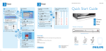
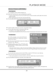
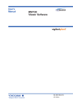
POCKET DMX
Fade
Time
Scroll
View
Record
Up
Down
Last
Next
Loop
7
8
9
4
5
6
1
2
3
@
Odd
0
Even
Enter
Cue
Stop
CLR
Go
POCKET DMX
User Manual
POCKET DMX
1 Introduction:
Thank you for your purchase of our product POCKET DMX .
This product POCKET DMX is a pocket DMX controller with a built-in chargeable
battery. The unit can realize the application of 512 channels output, and every channel
level can be set availably. Each output scene can be recorded as a Cue( up to 120 Cues
available ). These saved Cues can be operated singly, and also can they run orderly in
groups according to their numbers of sequence. The duration of each channel level’s
changing from the current level to the pre-set level can be appointed within 0~99 seconds.
The interval time between every two relevant Cues can be set within 1~99 seconds.
2 Features:
• LCD in 4 lines × 20 digits
• Full DMX 512 Channels output
• Numeric keypad with function key operation
• Interactive command line input
• Snap shot the incoming DMX signal to be Cue
3 Notice information:
Unpacking
This product has been thoroughly tested and carefully packed. Before operating,
please make sure that the unit has not suffered any damage and all accessories are not
missing. Should any damage have occurred, please do not use it and contact the local
dealer immediately.
Warning
• Keep the unit dry, do not expose it to water or high levels of humid.
• Do not try to dismantle or modify the product.
• Turn off the power if not using this unit for a long time.
• Any strong shocks or vibration may result in malfunction.
• This unit must operated by adults, do not allow children to play with it.
Copyright
No part of this product can be reproduced, transmitted, or translated into any language
in any form without authorized permission.
2
front
4 Controls and Functions:
view
4.1 Front panel
• 4×20 character LCD:
POCKET DMX
To display the operation menus.
• Function keyboard (32 keys)
To input relevant data or orders.
.4.2 Rear
panel
• DMX Input (3pin/5pin) :
Fa de
Time
Vi ew
Re cord
Up
Down
La st
Ne xt
Loop
7
8
9
4
5
6
1
2
3
@
Odd
0
Eve n
E nter
Cue
S top
CLR
Go
Used to input DMX signals.
S croll
• DMX Output (3pin/5pin) :
Used to output DMX signals.
• DC Input :
To input main power(DC 9V 500mA)
4.3 Bottom
panel
• Power switch:
To switch on / off the main power.
5 Operation
Guide
5.1 Basic operation
* Note: Cmd=Command, Act=Action, Chan/Ch=Channel, FL=FULL
Per=Percent (pattern), Dec=Decimal (pattern), Q=Cue, Clr=Clear .
5.1.1
Input method :
Input information on the Command (Cmd) line, and the corresponding result
will be displayed on the Action (Act) line.
Examples :
Command (input)
Action (result)
①××× Enter
Chan ××× FULL DONE
②××× @ yy Enter
Chan ××× at level yy DONE
③aaa > bbb Enter
Chan aaa thru Chan bbb Full DONE
④aaa + bbb + ccc @ ××× Enter
Chan aaa, bbb, ccc at level××× DONE
⑤aaa > bbb-ccc @
Chan aaa thru Chan bbb out Chan ccc at level
×××
Enter
×××
⑥aaa > bbb + ccc > ddd @
××
DONE
Enter Chan aaa thru Chan bbb, and Chan ccc thru
Chan ddd at level ×× DONE
3
5.1.2 CLR key
As Clear means, the CLR key can be used to cancel the previous step of input
information on the command line.
5.1.3
Odd / Even keys
When the input command has been finished, press Odd (Even) key, and then
press the “Enter” key, all the selected channels will output the levels only of the
Odd (Even) Channels. For example, input “1>100@80 Odd”, and press the
“Enter” key, LCD will show you:
Ch001>80
00
80
00
80
Ch006>00
80
00
80
00
Cmd : 1>100@80 Odd
Act : Done
That means the output at 80% level of all channels No. 1,3,5,7,9,……97,99.
5.1.4
Up / Down keys
Up/Down keys can be used to adjust the relevant Channel levels. When an
input command completed, press the Up/Down keys can increase/decrease the
relevant channel levels. Adjustment upon channel levels can be available within
the permitted range.
For example, input the command “1 > 40” and give a press upon the “Down”
key , the relevant levels of Ch1~Ch40 will respectively decrease by one level.
When all the channels has been adjusted back to 0 level, the LCD will show :
Ch016>00
00
00
00
00
Ch021>00
00
00
00
00
Cmd : 1>40_
Act : All chan zero
While all the channels has been adjusted to their maximum levels, the LCD
will show :
Ch016>FL FL FL FL FL
Ch021>FL FL FL FL FL
Cmd : 1>40_
Act : All chan full
4
5.1.5
Next / Last keys
Should the appointed channel level not be 0 level, press “Next” key, the next
channel level will be set to FL (FULL), while the levels of other channels will be set
to 0. On the contrary, press “Last” key in the same case, the previous channel
level will be set to FL, while other channel levels will be set to 0.
For example, input the command “20@90” on the LCD and press ”Enter” key
to confirm your operation, then press the “Next” key, the level of channel 21 will be
changed into FL, while other channel levels will be changed into 0.
5.1.6
Scroll keys “ ٧ ” and “ ٨ ”
Press “ ٧ ” or “ ٨” keys , the LCD will display in four lines just like the following:
Ch001>80
00
00
FL 80
Ch006>00
00
FL 00
00
Ch011>00
00
00
00
00
Ch016>00
00
00
00
00
When scroll function works, all the 4 lines of display will show in channels until
once a key input again. The display will show back into 2 lines of channel and 2
lines for Command and Action. Go on to press “ ٧ ” or ” ٨” keys to have a browse
of the display, and press any other key to exit this mode.
5.1.7
Changing Channel level patterns
Channel levels can be displayed in percent pattern (0%~100%) and in
decimal pattern (0~255). Press and hold the “view” key for about 5 seconds to
switch between these two patterns. The default pattern will be in Per(percent)
when the unit runs at its beginning.
5.1.8
To view the appointed Channel level
Input the relevant channel number and press “view” key, the corresponding
channel level will be displayed on the LCD. For example, input “30 view” on the
LCD, you will see :
Ch030>66
FL 55
FL 55
Ch035>55
FL 55
FL 00
Cmd : 30
Act : Chan Change
That means the current level of Ch30 is 66 .
5
5.2
Operation upon Cues
5.2.1
To record a Cue
When a scene has been completed by the basic operation or a snap shot
from the DMX connector (signals thru and merge in a HTP rule), input “Cue ××
×”
and press “Record” key, LCD will show you like the following display :
Ch001>60
00
60
Ch006>00
FL 00
00
60
FL 00
Cmd : Cue ×××
Act : Cue store
That means the Cue has been recorded successfully.
To make the received DMX data as Cue record data, you should input
“1>512@0”, press “Enter” key, and then input “Cue ××× Record”. And on the
other hand, to make the output channel data as Cue record data, you should
firstly switch off the input DMX signals, and then input “Cue ××× Record”.
5.2.2
To delete a Cue
To delete a recorded Cue, you should input “Cue ××× Stop”( ××× means
the recorded Cue number to be deleted ). For instance, if you want to delete
Cue 10, just input the command “Cue 10 Stop”, LCD will show you :
Ch001>85
80
00
00
40
Ch006>00
00
40
00
FL
Cmd : Cue 10
Act : The Cue del!
That means the Cue 10 has been deleted.
5.2.3
To view a Cue
To view a recorded view, you should input “Cue view”, and LCD will show you
all the recorded Cues in a menu :
Cue memory record
1> Cue 1
2> Cue 2
3> Cue 3
Press Up / Down keys to select the relevant Cue, and use “ ٧ ”、“ ٨ ” keys to
6
view through pages. Press “Enter” key to confirm your selection. For example, if
you want to view Cue 1, choose Cue 1 then press the “Enter” key, LCD shows:
Cue 1 :
Ch001>12
80
00
30
00
Ch006>00
20
00
50
00
Ch011>00
00
00
FL 00
By the way, you can also obtain the same view display by inputting the
command: “Cue 1 view” on the LCD-display.
5.2.4
Fade / Time setting for Cues
Fade just means the duration of Cue channel level’s changing from the
current level to the appointed level, it ranges between 0~99 seconds. Time just
means the interval time between every two relevant Cues, it ranges between
1~99 seconds. When the Fade is set to 0 level, all other Cues will be stopped
after the present running Cue finished. And when the Cue is set in Loop mode,
the appointed Cues can be operated circularly.
For instance, after the Cue5 menu was displayed, input “Fade@10” and
press the “Enter” key to confirm your operation, LCD will show you :
Cue 5 :
Ch001>12
80
00
30
00
Cmd : Fade@10
Act : Fade=10
( That means the Fade of Cue5 is 10 seconds )
The relevant fade time can also be viewed. For example, under the Cue5 menu, input
Fade and press the “Enter” key, LCD will show you the Fade time on the Action line :
Cue 5 :
Ch001>12
80
00
30
00
Cmd : Fade
Act : Fade=10
And you can also see the Fade time by directly inputting “Cue5 Fade” on the LCD.
(The Time setting can be done in the same way like Fade setting.)
7
5.2.5
Cue running
The Cues run automatically according to their different recorded number. For
instance just like the following :
Cue3, Fade=10, Time=5
Cue4, Fade=8 , Time=10
Cue5, Fade=15, Time=0
Cue10, Fade=10, Time=10
Input “Cue3 Go” to run the relevant operation, Cues will go like this: Cue3→Cue4→
Cue5. And LCD will show you:
Cue 3 :
Ch001>40
20
00
80
FL
Cmd : Q3 Go
Act : Cue3 Go Done
When under the Cue3 menu, directly input “Go“ to start the operation, LCD will show :
Cue 3 :
Ch001>40
20
00
80
FL
Cmd : Go
Act : Cue3 Go Done
And input “Cue4 Go” , the Cues will run like this : Cue4→Cue5.
To run circularly just like “Cue3→Cue4→Cue5→Cue3→…” , you should set the Time
of Cue5 as Loop mode, i.e. Cue5, Fade=15, Time=Loop.
5.2.6
Cue stop
Cue can be stopped at any time during its running. Just input “Cue Stop” , the running
Cue will be stopped. For instance, when the Cue 6 is running, input the command
“Cue Stop”, LCD will show you :
Cue 6 :
Ch001>00
11
00
11
00
Cmd : Cue
Act : Cue Stop
To make the running Cue stopped at its minimum outputting channel level, you should
input the Command ”Cue Down” on the LCD during the Cue’s running. When it stops
running, the LCD will show you :
8
Cue 6 :
Ch001>00
00
00
00
00
Cmd : Cue
Act : Cue run end !
6
Specifications:
• Power Input :
DC 9V 500mA
• Fuse :
F 0.5A 250V 5×20mm
• Input signals:
DMX signals, 512 channels(max)
• Output signals:
DMX signals, 512 channels(max)
• DMX Input :
3 pin / 5 pin connector
• DMX Output :
3 pin / 5 pin connector
• Dimensions:
209×136×63 mm
• Weight :
approx.
9
0.6 kg
Equipson, S.A.
www.equipson.es
[email protected]