1
Agilent 75000 Series C
Agilent E8460A
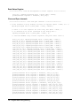
256-Channel Relay Multiplexer
User’s Manual and SCPI Programming Guide
Where to Find it - Online and Printed Information:
System installation (hardware/software) ............VXIbus Configuration Guide
(Supplied with Agilent Command Modules , Embedded Controllers, and VXLink. )
Module configuration and wiring .......................This Manual
SCPI programming .............................................This Manual
SCPI example programs .....................................This Manual, Driver Disk
SCPI command reference ..................................This Manual
Register-Based Programming.............................This Manual
VXIplug&play programming ............................VXIplug&play Online Help
VXIplug&play example programs .....................VXIplug&play Online Help
VXIplug&play function reference......................VXIplug&play Online Help
Soft Front Panel information ..............................VXIplug&play Online Help
VISA language information................................Agilent VISA User's Guide
Agilent VEE programming information.............Agilent VEE User's Manual
*E8460-90001*
Manual Part Number: E8460-90001
Printed in Malaysia E0912
Contents
Agilent E8460A 256-Channel Relay Multiplexer
AGILENT TECHNOLOGIES WARRANTY STATEMENT..................................... 5
Safety Symbols ............................................................................................................. 6
WARNINGS................................................................................................................. 6
Declaration of Conformity............................................................................................ 7
Chapter 1
Configuring the Agilent E8460A Multiplexer ........................................................... 11
Using This Chapter ..................................................................................................... 11
Module Description .................................................................................................... 11
Relay Organization .............................................................................................. 11
Analog Bus .......................................................................................................... 12
Terminal Cards .................................................................................................... 12
Warnings and Cautions............................................................................................... 14
Configuring the Multiplexer Module.......................................................................... 15
Setting the Logical Address ................................................................................ 15
Setting the Interrupt Priority Line ....................................................................... 16
Protection Resistors ............................................................................................. 16
Installing the Multiplexer in a Mainframe .................................................................. 17
Connecting Field Wiring ............................................................................................ 18
Terminal Connector Blocks ................................................................................ 18
Connecting the Analog Bus ................................................................................. 22
Terminal Cards .................................................................................................... 23
Programming the Multiplexer..................................................................................... 29
Specifying SCPI Commands ............................................................................... 29
Channel Address ................................................................................................. 29
Card Numbers ..................................................................................................... 30
Channel Numbers, Ranges, and Lists .................................................................. 31
Initial Operation .......................................................................................................... 32
Example: Reset, Self Test, Module ID, and Close Channel .............................. 33
Chapter 2
Using the Multiplexer .................................................................................................. 35
What’s in This Chapter ............................................................................................... 35
Reset Conditions ......................................................................................................... 35
Switching or Scanning ................................................................................................ 36
Switching Channels to the Analog Bus ............................................................... 36
1-Wire Mode ....................................................................................................... 39
2-Wire Mode ....................................................................................................... 40
3-Wire and 4-Wire Modes ................................................................................... 41
Other Modes ............................................................................................................... 41
Maximum Relay Closures ................................................................................... 41
Eight 32 x 1 Multiplexers .................................................................................... 43
Sixteen 16 x 1 Multiplexers ................................................................................ 44
Scanning Channels...................................................................................................... 45
Recalling and Saving States........................................................................................ 53
Saving States ....................................................................................................... 53
Recalling States ................................................................................................... 53
Detecting Error Conditions ......................................................................................... 54
Using Interrupts With Error Checking ................................................................ 54
Contents
1
Chapter 3
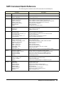
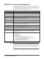
Multiplexer Command Reference .............................................................................. 55
ABORt ........................................................................................................................ 58
ARM ........................................................................................................................... 60
ARM:COUNt ...................................................................................................... 60
ARM:COUNt? .................................................................................................... 60
DIAGnostic................................................................................................................. 61
DIAGnostic:INTerrupt[:LINe] ............................................................................ 61
DIAGnostic:INTerrupt[:LINe]? .......................................................................... 62
DIAGnostic:CLOSe ............................................................................................ 62
DIAGnostic:CLOSe? .......................................................................................... 63
DIAGnostic:OPEN .............................................................................................. 64
DIAGnostic:OPEN? ............................................................................................ 65
DIAGnostic:TEST? ............................................................................................. 65
INITiate....................................................................................................................... 66
INITiate:CONTinuous ........................................................................................ 66
INITiate:CONTinuous? ....................................................................................... 67
INITiate[:IMMediate] ......................................................................................... 67
OUTPut....................................................................................................................... 68
OUTPut:ECLTrgn[:STATe] ............................................................................... 68
OUTPut:ECLTrgn[:STATe]? .............................................................................. 68
OUTPut[:EXTernal][:STATe] ............................................................................ 69
OUTPut[:EXTernal][:STATe]? .......................................................................... 69
OUTPut:TTLTrgn[:STATe] ................................................................................ 70
OUTPut:TTLTrgn[:STATe]? .............................................................................. 70
[ROUTe:] .................................................................................................................... 71
[ROUTe:]CLOSe ................................................................................................ 71
[ROUTe:]CLOSe? ............................................................................................... 73
[ROUTe:]FUNCtion ............................................................................................ 74
[ROUTe:]FUNCtion? .......................................................................................... 75
[ROUTe:]OPEN .................................................................................................. 75
[ROUTe:]OPEN? ................................................................................................ 76
[ROUTe:]SCAN .................................................................................................. 76
[ROUTe:]SCAN:MODE ..................................................................................... 77
[ROUTe:]SCAN:MODE? ................................................................................... 78
[ROUTe:]SCAN:PORT ...................................................................................... 78
[ROUTe:]SCAN:PORT? ..................................................................................... 79
STATus....................................................................................................................... 80
STATus:OPERation:CONDition? ...................................................................... 81
STATus:OPERation:ENABle ............................................................................. 81
STATus:OPERation:ENABle? ........................................................................... 81
STATus:OPERation[:EVENt]? ........................................................................... 82
STATus:PRESet .................................................................................................. 82
SYSTem...................................................................................................................... 84
SYSTem:CDEScription? ..................................................................................... 84
SYSTem:CPON .................................................................................................. 84
SYSTem:CTYPe? ............................................................................................... 85
SYSTem:ERRor? ................................................................................................ 85
2
Contents
TRIGger ...................................................................................................................... 86
TRIGger[:IMMediate] ......................................................................................... 86
TRIGger:SOURce ............................................................................................... 87
TRIGger:SOURce? ............................................................................................. 88
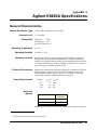
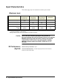
General Characteristics ............................................................................................... 91
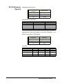
Input Characteristics ................................................................................................... 92
Maximum Input ................................................................................................... 92
DC Performance
(Typical) .............................................................................................................. 92
AC Performance
(Typical) .............................................................................................................. 93
Relay Life ............................................................................................................ 94
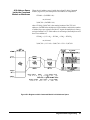
About This Appendix.................................................................................................. 95
Register Addressing .................................................................................................... 95
The Base Address ................................................................................................ 95
Register Offset ..................................................................................................... 98
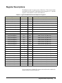
Register Descriptions .................................................................................................. 99
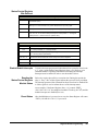
ID Register ........................................................................................................ 100
Device Type Register ........................................................................................ 100
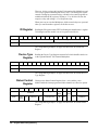
Status/Control Register ..................................................................................... 100
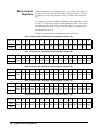
Relay Control Registers .................................................................................... 102
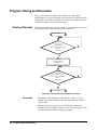
Program Timing and Execution ................................................................................ 106
Closing Channels ............................................................................................... 106
Using a Multimeter with the Multiplexer .......................................................... 107
Programming Example ............................................................................................. 108
System Configuration ........................................................................................ 108
Example Program .............................................................................................. 108
Error Types ............................................................................................................... 115
Contents
3
4
Contents
Certification
Agilent Technologies, Inc. certifies that this product met its published specifications at the time of shipment from the factory. Agilent
Technologies further certifies that its calibration measurements are traceable to the United States National Institute of Standards and
Technology (formerly National Bureau of Standards), to the extent allowed by that organization's calibration facility, and to the
calibration facilities of other International Standards Organization members.
AGILENT TECHNOLOGIES WARRANTY STATEMENT
PRODUCT: E8460A
DURATION OF WARRANTY: 1 year
1. Agilent warrants Agilent hardware, accessories and supplies against defects in materials and workmanship for the period specified
above. If Agilent receives notice of such defects during the warranty period, Agilent will, at its option, either repair or replace products
which prove to be defective. Replacement products may be either new or like-new.
2. Agilent warrants that Agilent software will not fail to execute its programming instructions, for the period specified above, due to
defects in material and workmanship when properly installed and used. If Agilent receives notice of such defects during the warranty
period, Agilent will replace software media which does not execute its programming instructions due to such defects.
3. Agilent does not warrant that the operation of Agilent products will be interrupted or error free. If Agilent is unable, within a reasonable
time, to repair or replace any product to a condition as warranted, customer will be entitled to a refund of the purchase price upon prompt
return of the product.
4. Agilent products may contain remanufactured parts equivalent to new in performance or may have been subject to incidental use.
5. The warranty period begins on the date of delivery or on the date of installation if installed by Agilent. If customer schedules or delays
Agilent installation more than 30 days after delivery, warranty begins on the 31st day from delivery.
6. Warranty does not apply to defects resulting from (a) improper or inadequate maintenance or calibration, (b) software, interfacing, parts
or supplies not supplied by Agilent Technologies, (c) unauthorized modification or misuse, (d) operation outside of the published
environmental specifications for the product, or (e) improper site preparation or maintenance.
7. TO THE EXTENT ALLOWED BY LOCAL LAW, THE ABOVE WARRANTIES ARE EXCLUSIVE AND NO OTHER
WARRANTY OR CONDITION, WHETHER WRITTEN OR ORAL, IS EXPRESSED OR IMPLIED AND AGILENT
SPECIFICALLY DISCLAIMS ANY IMPLIED WARRANTY OR CONDITIONS OF MERCHANTABILITY, SATISFACTORY
QUALITY, AND FITNESS FOR A PARTICULAR PURPOSE.
8. Agilent will be liable for damage to tangible property per incident up to the greater of $300,000 or the actual amount paid for the product
that is the subject of the claim, and for damages for bodily injury or death, to the extent that all such damages are determined by a court
of competent jurisdiction to have been directly caused by a defective Agilent product.
9. TO THE EXTENT ALLOWED BY LOCAL LAW, THE REMEDIES IN THIS WARRANTY STATEMENT ARE CUSTOMER’S
SOLE AND EXLUSIVE REMEDIES. EXCEPT AS INDICATED ABOVE, IN NO EVENT WILL AGILENT OR ITS SUPPLIERS BE
LIABLE FOR LOSS OF DATA OR FOR DIRECT, SPECIAL, INCIDENTAL, CONSEQUENTIAL (INCLUDING LOST PROFIT OR
DATA), OR OTHER DAMAGE, WHETHER BASED IN CONTRACT, TORT, OR OTHERWISE.
FOR CONSUMER TRANSACTIONS IN AUSTRALIA AND NEW ZEALAND: THE WARRANTY TERMS CONTAINED IN THIS
STATEMENT, EXCEPT TO THE EXTENT LAWFULLY PERMITTED, DO NOT EXCLUDE, RESTRICT OR MODIFY AND ARE
IN ADDITION TO THE MANDATORY STATUTORY RIGHTS APPLICABLE TO THE SALE OF THIS PRODUCT TO YOU.
U.S. Government Restricted Rights
The Software and Documentation have been developed entirely at private expense. They are delivered and licensed as "commercial
computer software" as defined in DFARS 252.227- 7013 (Oct 1988), DFARS 252.211-7015 (May 1991) or DFARS 252.227-7014 (Jun
1995), as a "commercial item" as defined in FAR 2.101(a), or as "Restricted computer software" as defined in FAR 52.227-19 (Jun
1987)(or any equivalent agency regulation or contract clause), whichever is applicable. You have only those rights provided for such
Software and Documentation by the applicable FAR or DFARS clause or the Agilent standard software agreement for the product
involved.
IEC Measurement Category II Overvoltage Protection
This is a measurement Category II product designed for measurements at voltages up to 300V from earth, including measurements of
voltages at typical mains socket outlets. The product should not be used to make voltage measurements on a fixed electrical installation
including building wiring, circuit breakers, or service panels.
E8460A 256-Channel Relay Multiplexer User Manual
Edition 2 Rev 3
Copyright © 1998-2006 Agilent Technologies, Inc. All Rights Reserved.
5
Documentation History
All Editions and Updates of this manual and their creation date are listed below. The first Edition of the manual is Edition 1. The Edition
number increments by 1 whenever the manual is revised. Updates, which are issued between Editions, contain replacement pages to
correct or add additional information to the current Edition of the manual. Whenever a new Edition is created, it will contain all of the
Update information for the previous Edition. Each new Edition or Update also includes a revised copy of this documentation history page.
Edition 1 . . . . . . . . . . . . . . . . . . . . . . . . . . . . . . . . . . July 1997
Edition 2 (E8460-90001) . . . . . . . . . . . . . . . . . . . . . April 1998
Edition 2 Rev 2 (E8460-90001). . . . . . . . . . . . . . . . .May 2006
Edition 2 Rev 3 (E8460-90001). . . . . . . . . . . . September 2012
Trademarks
Microsoft® is a U.S. registered trademark of Microsoft Corporation
Windows NT® is a U.S. registered trademark of Microsoft Corporation
Windows® and MS Windows® are U.S. registered trademarks of Microsoft Corporation are U.S. registered trademarks of Microsoft
Safety Symbols
Instruction manual symbol affixed to
product. Indicates that the user must refer to
the manual for specific WARNING or
CAUTION information to avoid personal
injury or damage to the product.
Alternating current (AC)
Direct current (DC).
Indicates hazardous voltages.
Indicates the field wiring terminal that must
be connected to earth ground before
operating the equipment—protects against
electrical shock in case of fault.
or
Frame or chassis ground terminal—typically
connects to the equipment's metal frame.
Calls attention to a procedure, practice, or
WARNING condition that could cause bodily injury or
death.
Calls attention to a procedure, practice, or
CAUTION condition that could possibly cause damage to
equipment or permanent loss of data.
WARNINGS
The following general safety precautions must be observed during all phases of operation, service, and repair of this product. Failure to
comply with these precautions or with specific warnings elsewhere in this manual violates safety standards of design, manufacture, and
intended use of the product. Agilent Technologies, Inc. assumes no liability for the customer's failure to comply with these requirements.
Ground the equipment: For Safety Class 1 equipment (equipment having a protective earth terminal), an uninterruptible safety earth
ground must be provided from the mains power source to the product input wiring terminals or supplied power cable.
DO NOT operate the product in an explosive atmosphere or in the presence of flammable gases or fumes.
For continued protection against fire, replace the line fuse(s) only with fuse(s) of the same voltage and current rating and type. DO NOT
use repaired fuses or short-circuited fuse holders.
Keep away from live circuits: Operating personnel must not remove equipment covers or shields. Procedures involving the removal of
covers or shields are for use by service-trained personnel only. Under certain conditions, dangerous voltages may exist even with the
equipment switched off. To avoid dangerous electrical shock, DO NOT perform procedures involving cover or shield removal unless you
are qualified to do so.
DO NOT operate damaged equipment: Whenever it is possible that the safety protection features built into this product have been
impaired, either through physical damage, excessive moisture, or any other reason, REMOVE POWER and do not use the product until
safe operation can be verified by service-trained personnel. If necessary, return the product to an Agilent Technologies Sales and Service
Office for service and repair to ensure that safety features are maintained.
DO NOT service or adjust alone: Do not attempt internal service or adjustment unless another person, capable of rendering first aid and
resuscitation, is present.
DO NOT substitute parts or modify equipment: Because of the danger of introducing additional hazards, do not install substitute parts
or perform any unauthorized modification to the product. Return the product to an Agilent Technologies Sales and Service Office for
service and repair to ensure that safety features are maintained.
6
Declaration of Conformity
Declarations of Conformity for this product and for other Agilent products may be downloaded from the Internet. There are
two methods to obtain the Declaration of Conformity:
• Go to http://regulations.corporate.agilent.com/DoC/search.htm. You can then search by product number to find
the latest Declaration of Conformity.
• Alternately, you can go to the product web page (www.agilent.com/find/E8460A), click on the Document
Library tab then scroll down until you find the Declaration of Conformity link.
7
Notes:
8
Notes:
9
Notes:
10
Chapter 1
Configuring the Agilent E8460A
Multiplexer
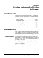
Using This Chapter
This chapter provides general module information, vital WARNINGS and
CAUTIONS, and the tasks you must perform to configure and install the
Agilent E8460A Relay Multiplexer. It also provides information to verify
the module installation. Chapter contents are:
• Module Description. . . . . . . . . . . . . . . . . . . . . . . . . . . . . . . .
• Warnings and Cautions . . . . . . . . . . . . . . . . . . . . . . . . . . . . .
• Configuring the Multiplexer Module . . . . . . . . . . . . . . . . . .
• Installing the Multiplexer in a Mainframe . . . . . . . . . . . . . .
• Connecting Field Wiring. . . . . . . . . . . . . . . . . . . . . . . . . . . .
• Terminal Cards . . . . . . . . . . . . . . . . . . . . . . . . . . . . . . . . . . .
• Programming the Multiplexer . . . . . . . . . . . . . . . . . . . . . . . .
• Initial Operation . . . . . . . . . . . . . . . . . . . . . . . . . . . . . . . . . .
Page 11
Page 12
Page 15
Page 17
Page 18
Page 23
Page 29
Page 32
Module Description
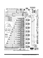
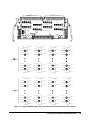
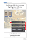
Figure 1-1 shows the simplified block diagram of the Agilent E8460A, the
Option 015 Ribbon Cable Connector Terminal Card, and a simple measurement application. Notice the sixteen 100 protection resistors; one in series
with each bank line. Refer to Figure 1-1 for the following description.
Relay Organization
The Agilent E8460A Relay Multiplexer is organized as 16 banks (Bank 0
through Bank 15) of 16 channels each (Channel 000 - Ch 015, Ch 016 - Ch
031, Ch 032 - Ch 047, ... Ch 240 - Ch 255). The default configuration is for
256 channels of 1-wire switches.
Tree relays T1 through T48 (Channel 300 through Channel 347) configure
the module to the desired operating mode: 1-wire, 2-wire, 3-wire and 4-wire
modes. In addition, the tree relays can configure this module as eight 32 x 1
or sixteen 16 x 1 multiplexers.
Relays T49 through T52 (Channels 990 through 994) are the analog bus
connection control relays which connect the terminal busses to the analog
bus.
Configuring the Agilent E8460A Multiplexer
11
Analog Bus
The “Analog Bus Front Panel Connector” on the module allows you to
connect this Multiplexer to to an VXI multimeter (such as the Agilent
E1411A/B and/or E1326A/B) directly.
The optional Fault Tolerant Terminal Card (Option 014) distributes the
analog bus from P109 in the Terminal Card. You can connect this
Multiplexer to an Agilent E1412A Multimeter or other instruments via a
ribbon cable (not supplied).
Terminal Cards
No terminal card or connectors are supplied with the Agilent E8460A. You
may purchase 160-pin terminal blocks (order Agilent part number
1252-6531 or direct from the manufacturer ERNI pn 0240701) and the
necessary crimp-and-insert contacts (Agilent pn for one contact is
1252-6533A, or ERNI pn 014728). You will also need a crimp tool (Agilent
pn 8710-2306 or ERNI pn 014374) and optionally a disassembly tool
(Agilent pn 8710-2307 or ERNI pn 471555).
You may also purchase one of the three optional terminal cards from
Agilent:
• Option 012 Crimp & Insert Terminal Card uses the same terminal
block and crimp connectors described above but provides strain relief
and a terminal card housing. Refer to Option 012 Crimp-and-Insert
Terminal Block on page 23.
• Option 014 Fault Tolerant Terminal Card provides nine ribbon-cable
header connectors (P101-P109). P101 through P108 contain 16
terminals (Ter0 through Ter15) and all the 256 channels
(CH000-CH255) and P109 is the analog bus connector. Refer to
Option 014 Fault Tolerant Terminal Block on page 23.
• Option 015 Ribbon Cable Connector Terminal Card provides nine
ribbon-cable header connectors (P101-P109) identical to option 014.
This terminal module is identical to the option 014 terminal module
except that the PTC resistors (fault tolerant protection resistors) are
replaced with shorts. All this terminal card provides is a convenient
means to connect ribbon cable from field wiring to the module.
1. Contact ERNI Components, A Division of ODIN Components, Inc. 520 Southlake Blvd., Richmond, VA
23236, U.S.A. Telephone, (804) 794-6367, FAX (804) 379-2109.
12
Configuring the Agilent E8460A Multiplexer
W
Figure 1-1. Agilent E8460A Simplified Schematic
Configuring the Agilent E8460A Multiplexer
13
Warnings and Cautions
14
WARNING
SHOCK HAZARD. Only qualified, service-trained personnel who
are aware of the hazards involved should install, configure, or
remove the Multiplexer Module. Disconnect all power sources
from the mainframe, the Terminal Cards, and installed modules
before installing or removing a module.
WARNING
When handling user wiring connected to the Terminal Card,
consider the highest voltage present accessible on any
terminal. Use only wire with an insulation rating greater than
the highest voltage which will be present on the Terminal Card.
Do not touch any circuit element connected to the Terminal
Card if any other connector to the Terminal Card is energized to
more than 30VACRMS or 60VDC.
Caution
MAXIMUM VOLTAGE/CURRENT. Maximum allowable voltage
per channel, terminal-to-terminal or terminal-to-chassis for the
Multiplexer is 200 VDC, 140 VACrms, or 200VACpeak. Maximum
switching current per channel is 500 mA (non-inductive).
Maximum transient voltage is 1200V peak. Exceeding any limit
may damage the Multiplexer Module.
Caution
WIRING THE TERMINAL CARD. When wiring to the terminal
connectors on the Agilent E8460A Terminal Card, be sure not to
exceed a 5mm strip back of insulation to prevent the possibility
of shorting to other wiring on adjacent terminals.
Caution
STATIC ELECTRICITY. Static electricity is a major cause of
component failure. To prevent damage to the electrical
components in the Multiplexer, observe anti-static techniques
whenever removing, configuring, and installing a module. The
Multiplexer is susceptible to static discharges. Do not install
the Multiplexer Module without its metal shield attached.
Configuring the Agilent E8460A Multiplexer
Configuring the Multiplexer Module
The Multiplexer module can be configured to the operating modes through
the VXIplug&play driver or via SCPI commands. These drivers are located
on the supplied CD-ROM. Before installing the module into a VXIbus
mainframe (e.g. Agilent E1401A), you need to set the Multiplexer’s logical
address.
Setting the Logical
Address
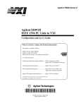
The factory default logical address switch setting is 112. Valid addresses are
from 1 to 254 for static configuration and address 255 for dynamic
configuration. The Agilent E8460A supports dynamic configuration of the
address. This means the address is set programmatically by the resource
manager when it encounters a module with address 255.
The logical addresses must be sequential if multiple modules are used to
form a switchbox. See Figure 1-13. "Card Numbers in a Multiple-module
Configuration" on page 30 for more information.
Refer to the C-Size VXIbus System Installation and Getting Started Guide
for addressing information. Figure 1-2 shows the logical address switch
position.
Figure 1-2. Setting the Logical Address
Configuring the Agilent E8460A Multiplexer
15
Setting the Interrupt
Priority Line
For most applications the default priority line should not have to be changed.
An interrupt is generated after any channel is opened or closed when
interrupts are enabled. The interrupt is generated approximately 500 s after
command execution allowing for relay settling time. The interrupt line can
be set to any one of the VXI backplane lines 1-7 through writing the bits 10,
9 and 8 of the Status/Control Register. The default value is 1. The interrupt
can be disabled at power-up, after a SYSRESET, or after resetting the
module via the Control Register.
See Appendix B, Agilent E8460A Register-Based Programming for more
information of setting the interrupt priority line by writing to the
Status/Control Register.
Protection
Resistors
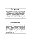
Figure 1-1 shows the 100 protection resistors in series with each bank line.
These protection resistors limit the maximum current through the relays.
However, in some measurements (such as 2-Wire resistance measurements)
you may want to bypass the protection resistors. Each resistor has a jumper
(J601 for Bank 0, JP602 for Bank 1, JP 603 for Bank2, . . . JP616 for Bank
15) across it allowing you to short out the resistor if necessary. Refer to
Figure 1-3. The default is to have the jumper in the offset position so the
resistor is not shorted.
=
(default)
=
Figure 1-3. Protection Resistors and Jumpers
16
Configuring the Agilent E8460A Multiplexer
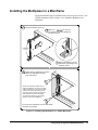
Installing the Multiplexer in a Mainframe
The Agilent E8460A may be installed in any slot (except slot 0) in a C-size
VXIbus mainframe. Refer to Figure 1-4 to install the Multiplexer in a
mainframe.
1
Set the extraction levers out.
2 Slide the HP
into any slot
(except slot 0) until the backplane
connectors touch.
Extraction
Levers
3 Seat the multiplexer into the
mainframe by pushing in the
extraction levers
4 Tighten the top and bottom screws to
secure the multiplexer module
to the mainframe.
NOTE: The extraction levers will not
seat the backplane connectors on older
VXIbus mainframes. You must manually
seat the connectors by pushing in the
module until the module's front panel is
flush with the front of the mainframe.
The extraction levers may be used to
guide or remove the multiplexer.
To remove the multiplexer from the mainframe,
reverse the procedure.
Figure 1-4. Installing the Multiplexer in a VXIbus Mainframe
Configuring the Agilent E8460A Multiplexer
17
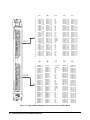
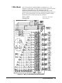
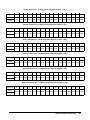
Connecting Field Wiring
As mentioned before, the Agilent E8460A is not supplied with terminal
connector blocks or terminal cards. Figure 1-6 shows the Multiplexer's front
panel and the connector pin-out.
Ter0 to Ter15 refer to Terminal 0 through Terminal 15. T_ACCESS* and
T_ERROR* are two signals to drive LEDs on the Option 012 Terminal
Card. “NC” refers to “Not Connected” and “CGND” refers to “Chassis
Ground”.
Terminal Connector
Blocks
Caution
Refer to Figure 1-5. You may purchase 160-pin terminal connector blocks
(two are required, order Agilent part number 1252-6531 or direct from the
manufacturer, ERNI part number 024070) and the necessary
crimp-and-insert contacts (Agilent pn for single contact is 1252-6533, or
ERNI pn 014728). The contacts are gold-plated, accept a wire size of 20 to
26AWG, and carry a maximum current of 2A @70°C. You will also need a
crimp tool (Agilent pn 8710-2306 or ERNI pn 014374) and optionally a
disassembly tool (Agilent pn 8710-2307 or ERNI pn 471555).
Due to the close terminal spacing and the potential for
pin-to-pin leakage, the terminal connector blocks must be
replaced after 10,000 hours of use if the module regularly
switches voltages greater than 60VDC, 50VACrms, or 70.7
VACpeak.
A single-conductor with contact (a crimp-and-insert contact is crimped onto
one end, the other end is not terminated) is available as Agilent pn
8150-5207.
Length: 2 meters
Wire Gauge: 24 AWG
Insulation Rating: 105 C maximum
Voltage: 300 V maximum
Figure 1-5. Terminal Connector Block and Single-Conductor Wire with Contact
18
Configuring the Agilent E8460A Multiplexer
A1
256 -CHANNEL
MULTIPLEXER
CH000
CH096
J1 01
CH031
CH127
CH128
CH224
J1 02
CH159
HP E8460A
CH255
C H0 00
C H0 01
C H0 02
C H0 03
C H0 04
C H0 05
C H0 06
C H0 07
C H0 08
C H0 09
C H0 10
C H0 11
C H0 12
C H0 13
C H0 14
C H0 15
C H0 16
C H0 17
C H0 18
C H0 19
C H0 20
C H0 21
C H0 22
C H0 23
C H0 24
C H0 25
C H0 26
C H0 27
C H0 28
C H0 29
C H0 30
C H0 31
B1
to
to
to
to
to
to
to
to
to
to
to
to
to
to
to
to
to
to
to
to
to
to
to
to
to
to
to
to
to
to
to
to
H1
H1
H1
H1
H1
H1
H1
H1
H1
H1
H1
H1
H1
H1
H1
H1
H1
H1
H1
H1
H1
H1
H1
H1
H1
H1
H1
H1
H1
H1
H1
H1
A2
C H1 28
C H1 29
C H1 30
C H1 31
C H1 32
C H1 33
C H1 34
C H1 35
C H1 36
C H1 37
C H1 38
C H1 39
C H1 40
C H1 41
C H1 42
C H1 43
C H1 44
C H1 45
C H1 46
C H1 47
C H1 48
C H1 49
C H1 50
C H1 51
C H1 52
C H1 53
C H1 54
C H1 55
C H1 56
C H15 7
C H1 58
C H1 59
CH032
CH033
CH034
CH035
CH036
CH037
CH038
CH039
CH040
CH0 41
CH042
CH043
CH044
CH045
CH046
CH047
CH048
CH049
CH050
CH051
CH052
CH053
CH054
CH055
CH056
CH057
CH058
CH059
CH060
CH061
CH062
CH063
to
to
to
to
to
to
to
to
to
to
to
to
to
to
to
to
to
to
to
to
to
to
to
to
to
to
to
to
to
to
to
to
H1
H1
H1
H1
H1
H1
H1
H1
H1
H1
H1
H1
H1
H1
H1
H1
H1
H1
H1
H1
H1
H1
H1
H1
H1
H1
H1
H1
H1
H1
H1
H1
B2
to
to
to
to
to
to
to
to
to
to
to
to
to
to
to
to
to
to
to
to
to
to
to
to
to
to
to
to
to
to
to
to
H1
H1
H1
H1
H1
H1
H1
H1
H1
H1
H1
H1
H1
H1
H1
H1
H1
H1
H1
H1
H1
H1
H1
H1
H1
H1
H1
H1
H1
H1
H1
H1
C H160
C H161
C H162
C H163
C H164
C H165
C H166
C H167
C H168
C H1 69
C H170
C H171
C H172
C H173
C H174
C H175
C H176
C H177
C H178
C H179
C H180
C H181
C H182
C H183
C H184
C H185
C H186
C H187
C H188
C H189
C H190
C H191
to
to
to
to
to
to
to
to
to
to
to
to
to
to
to
to
to
to
to
to
to
to
to
to
to
to
to
to
to
to
to
to
H1
H1
H1
H1
H1
H1
H1
H1
H1
H1
H1
H1
H1
H1
H1
H1
H1
H1
H1
H1
H1
H1
H1
H1
H1
H1
H1
H1
H1
H1
H1
H1
C1
D1
NC
NC
NC
Te r 0
NC
H1
NC
Te r 1
NC
NC
NC
Te r 2
NC
L1
NC
Te r 3
CGND
CGND
CGND
Te r 4
NC
L2
NC
Te r 5
NC
G
NC
Te r 6
NC
H2
NC
Te r 7
CH064
CH065
CH066
CH067
CH068
CH069
CH070
CH071
CH072
CH0 73
CH074
CH075
CH076
CH077
CH078
CH079
CH080
CH081
CH082
CH083
CH084
CH085
CH086
CH087
CH088
CH089
CH090
CH091
CH092
CH093
CH094
CH095
C2
D2
T_ACC ESS*
T_ERRO R*
NC
Te r 8
NC
NC
NC
Te r 9
NC
NC
NC
Te r 10
NC
NC
NC
Te r 11
CGND
CGND
CGND
Te r 12
NC
NC
NC
Te r 1 3
NC
NC
NC
Te r 14
NC
NC
NC
Te r 15
C H192
C H193
C H194
C H195
C H196
C H197
C H198
C H199
C H200
C H201
C H202
C H203
C H204
C H205
C H206
C H207
C H208
C H209
C H210
C H211
C H212
C H213
C H214
C H215
C H216
C H217
C H218
C H219
C H220
C H221
C H222
C H223
E1
to
to
to
to
to
to
to
to
to
to
to
to
to
to
to
to
to
to
to
to
to
to
to
to
to
to
to
to
to
to
to
to
H1
H1
H1
H1
H1
H1
H1
H1
H1
H1
H1
H1
H1
H1
H1
H1
H1
H1
H1
H1
H1
H1
H1
H1
H1
H1
H1
H1
H1
H1
H1
H1
CH096
CH097
CH098
CH099
CH100
CH101
CH102
CH103
CH104
CH105
CH106
CH107
CH108
CH109
CH110
CH111
CH112
CH113
CH114
CH115
CH116
CH117
CH118
CH119
CH120
CH121
CH122
CH123
CH124
CH125
CH126
CH127
to
to
to
to
to
to
to
to
to
to
to
to
to
to
to
to
to
to
to
to
to
to
to
to
to
to
to
to
to
to
to
to
H1
H1
H1
H1
H1
H1
H1
H1
H1
H1
H1
H1
H1
H1
H1
H1
H1
H1
H1
H1
H1
H1
H1
H1
H1
H1
H1
H1
H1
H1
H1
H1
to
to
to
to
to
to
to
to
to
to
to
to
to
to
to
to
to
to
to
to
to
to
to
to
to
to
to
to
to
to
to
to
H1
H1
H1
H1
H1
H1
H1
H1
H1
H1
H1
H1
H1
H1
H1
H1
H1
H1
H1
H1
H1
H1
H1
H1
H1
H1
H1
H1
H1
H1
H1
H1
E2
to
to
to
to
to
to
to
to
to
to
to
to
to
to
to
to
to
to
to
to
to
to
to
to
to
to
to
to
to
to
to
to
H1
H1
H1
H1
H1
H1
H1
H1
H1
H1
H1
H1
H1
H1
H1
H1
H1
H1
H1
H1
H1
H1
H1
H1
H1
H1
H1
H1
H1
H1
H1
H1
C H224
C H225
C H226
C H227
C H228
C H229
C H230
C H231
C H232
C H233
C H234
C H235
C H236
C H237
C H238
C H239
C H240
C H241
C H242
C H243
C H244
C H245
C H246
C H247
C H248
C H249
C H250
C H251
C H252
C H253
C H254
C H255
Figure 1-6. Agilent E8460A Multiplexer Front Panel Pin-out 1-WIre Mode, (Default)
Configuring the Agilent E8460A Multiplexer
19
A1
256 -CHANNEL
MULTIPLEXER
J1 01
C H0 00
C H0 01
C H0 02
C H0 03
C H0 04
C H0 05
C H0 06
C H0 07
C H0 08
C H0 09
C H0 10
C H0 11
C H0 12
C H0 13
C H0 14
C H0 15
C H0 16
C H0 17
C H0 18
C H0 19
C H0 20
C H0 21
C H0 22
C H0 23
C H0 24
C H0 25
C H0 26
C H0 27
C H0 28
C H0 29
C H0 30
C H0 31
B1
to
to
to
to
to
to
to
to
to
to
to
to
to
to
to
to
to
to
to
to
to
to
to
to
to
to
to
to
to
to
to
to
A2
J1 02
HP E8460A
CH064 to
CH065 to
CH066 to
CH067 to
CH068 to
CH069 to
CH070 to
CH071 to
CH072 to
CH073 to
CH074 to
CH075 to
CH076 to
CH077 to
CH078 to
CH079 to
CH080 to
CH081 to
CH082 to
CH083 to
CH084 to
CH085 to
CH086 to
CH087 to
CH088 to
CH089 to
CH090 to
CH091 to
CH092 to
CH093 to
CH094 to
CH095 to
H1
H1
H1
H1
H1
H1
H1
H1
H1
H1
H1
H1
H1
H1
H1
H1
H1
H1
H1
H1
H1
H1
H1
H1
H1
H1
H1
H1
H1
H1
H1
H1
CH 0 00 to L 1
CH 0 01 to L 1
CH 0 02 to L 1
CH 0 03 to L 1
CH 0 04 to L 1
CH 0 05 to L 1
CH 0 06 to L 1
CH 0 07 to L 1
CH 0 08 to L 1
CH 0 09 to L 1
CH 0 10 to L 1
CH 0 11 to L 1
CH 0 12 to L 1
CH 0 13 to L 1
CH 0 14 to L 1
CH 0 15 to L 1
CH 0 16 to L 1
CH 0 17 to L 1
CH 0 18 to L 1
CH 0 19 to L 1
CH 0 20 to L 1
CH 0 21 to L 1
CH 0 22 to L 1
CH 0 23 to L 1
CH 0 24 to L 1
CH 0 25 to L 1
CH 0 26 to L 1
CH 0 27 to L 1
CH 0 28 to L 1
CH 0 29 to L 1
CH 0 30 to L 1
CH 0 31 to L 1
B2
H1
H1
H1
H1
H1
H1
H1
H1
H1
H1
H1
H1
H1
H1
H1
H1
H1
H1
H1
H1
H1
H1
H1
H1
H1
H1
H1
H1
H1
H1
H1
H1
CH064 to L1
CH065 to L1
CH066 to L1
CH067 to L1
CH068 to L1
CH069 to L1
CH070 to L1
CH071 to L1
CH072 to L1
CH073 to L1
CH074 to L1
CH075 to L1
CH076 to L1
CH077 to L1
CH078 to L1
CH079 to L1
CH080 to L1
CH081 to L1
CH082 to L1
CH083 toL1
CH084 to L1
CH085 to L1
CH086 to L1
CH087 to L1
CH088 to L1
CH089 to L1
CH090 to L1
CH091 to L1
CH092 to L1
CH093 to L1
CH094 to L1
CH095 to L1
C1
D1
NC
NC
NC
Te r 0
NC
H1
NC
Te r 1
NC
NC
NC
Te r 2
NC
L1
NC
Te r 3
CGND
CGND
CGND
Te r 4
NC
L2
NC
Te r 5
NC
G
NC
Te r 6
NC
H2
NC
Te r 7
CH 032
CH 033
CH 034
CH 035
CH 036
CH 037
CH 038
CH 039
CH 040
CH0 41
CH 042
CH 043
CH 044
CH 045
CH 046
CH 047
CH 048
CH 049
CH 050
CH 051
CH 052
CH 053
CH 054
CH 055
CH 056
CH 057
CH 058
CH 059
CH 060
CH 061
CH 062
CH 063
C2
D2
T_ACC ESS*
T_ERRO R*
NC
Te r 8
NC
NC
NC
Te r 9
NC
NC
NC
Te r 10
NC
NC
NC
Te r 11
CGND
CGND
CGND
Te r 12
NC
NC
NC
Te r 1 3
NC
NC
NC
Te r 14
NC
NC
NC
Te r 15
E1
to
to
to
to
to
to
to
to
to
to
to
to
to
to
to
to
to
to
to
to
to
to
to
to
to
to
to
to
to
to
to
to
H2
H2
H2
H2
H2
H2
H2
H2
H2
H2
H2
H2
H2
H2
H2
H2
H2
H2
H2
H2
H2
H2
H2
H2
H2
H2
H2
H2
H2
H2
H2
H2
CH096 to H2
CH097 to H2
CH098 to H2
CH099 to H2
CH100 to H2
CH101 to H2
CH102 to H2
CH103 to H2
CH104 to H2
CH105 to H2
CH106 to H2
CH107 to H2
CH108 to H2
CH109 to H2
CH110 to H2
CH111 to H2
CH112 to H2
CH113 to H2
CH114 to H2
CH115 to H2
CH116 to H2
CH117 to H2
CH118 to H2
CH119 to H2
CH120 to H2
CH121 to H2
CH122 to H2
CH123 to H2
CH124 to H2
CH125 to H2
CH126 to H2
CH127 to H2
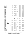
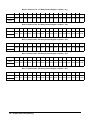
Figure 1-7. Agilent E8460A Multiplexer Front Panel Pin-out 2-Wire Mode
20
Configuring the Agilent E8460A Multiplexer
CH032
CH033
CH034
CH035
CH036
CH037
CH038
CH039
CH040
CH0 41
CH042
CH043
CH044
CH045
CH046
CH047
CH04 8
CH049
CH050
CH051
CH052
CH053
CH054
CH055
CH056
CH057
CH058
CH059
CH060
CH061
CH062
CH063
to
to
to
to
to
to
to
to
to
to
to
to
to
to
to
to
to
to
to
to
to
to
to
to
to
to
to
to
to
to
to
to
E2
CH096 to L2
CH097 to L2
CH098 to L2
CH099 to L2
CH100 to L2
CH101 to L2
CH102 to L2
CH103 to L2
CH104 to L2
CH105 to L2
CH106 to L2
CH107 to L2
CH108 to L2
CH109 to L2
CH110 to L2
CH111 to L2
CH112 to L2
CH113 to L2
CH114 to L2
CH115 to L2
CH116 to L2
CH117 to L2
CH118 to L2
CH119 to L2
CH120 to L2
CH121 to L2
CH122 to L2
CH123 to L2
CH124 to L2
CH125 to L2
CH126 to L2
CH127 to L2
L2
L2
L2
L2
L2
L2
L2
L2
L2
L2
L2
L2
L2
L2
L2
L2
L2
L2
L2
L2
L2
L2
L2
L2
L2
L2
L2
L2
L2
L2
L2
L2
A1
256 -CHANNEL
MULTIPLEXER
J1 01
C H0 00
C H0 01
C H0 02
C H0 03
C H0 04
C H0 05
C H0 06
C H0 07
C H0 08
C H0 09
C H0 10
C H0 11
C H0 12
C H0 13
C H0 14
C H0 15
C H0 16
C H0 17
C H0 18
C H0 19
C H0 20
C H0 21
C H0 22
C H0 23
C H0 24
C H0 25
C H0 26
C H0 27
C H0 28
C H0 29
C H0 30
C H0 31
B1
to
to
to
to
to
to
to
to
to
to
to
to
to
to
to
to
to
to
to
to
to
to
to
to
to
to
to
to
to
to
to
to
H1
H1
H1
H1
H1
H1
H1
H1
H1
H1
H1
H1
H1
H1
H1
H1
H1
H1
H1
H1
H1
H1
H1
H1
H1
H1
H1
H1
H1
H1
H1
H1
A2
J1 02
HP E8460A
CH032 to
CH033 to
CH034 to
CH035 to
CH036 to
CH037 to
CH038 to
CH039 to
CH040 to
CH041 to
CH042 to
CH043 to
CH044 to
CH045 to
CH046 to
CH047 to
CH048 to
CH049 to
CH050 to
CH051 to
CH052 to
CH053 to
CH054 to
CH055 to
CH056 to
CH057 to
CH058 to
CH059 to
CH060 to
CH061 to
CH062 to
CH063 to
C1
CH 0 00 to L 1
CH 0 01 to L 1
CH 0 02 to L 1
CH 0 03 to L 1
CH 0 04 to L 1
CH 0 05 to L 1
CH 0 06 to L 1
CH 0 07 to L 1
CH 0 08 to L 1
CH 0 09 to L 1
CH 0 10 to L 1
CH 0 11 to L 1
CH 0 12 to L 1
CH 0 13 to L 1
CH 0 14 to L 1
CH 0 15 to L 1
CH 0 16 to L 1
CH 0 17 to L 1
CH 0 18 to L 1
CH 0 19 to L 1
CH 0 20 to L 1
CH 0 21 to L 1
CH 0 22 to L 1
CH 0 23 to L 1
CH 0 24 to L 1
CH 0 25 to L 1
CH 0 26 to L 1
CH 0 27 to L 1
CH 0 28 to L 1
CH 0 29 to L 1
CH 0 30 to L 1
CH 0 31 to L 1
B2
H1
H1
H1
H1
H1
H1
H1
H1
H1
H1
H1
H1
H1
H1
H1
H1
H1
H1
H1
H1
H1
H1
H1
H1
H1
H1
H1
H1
H1
H1
H1
H1
CH032 to
CH033 to
CH034 to
CH035 to
CH036 to
CH037 to
CH038 to
CH039 to
CH040 to
CH041 to
CH042 to
CH043 to
CH044 to
CH045 to
CH046 to
CH047 to
CH048 to
CH049 to
CH050 to
CH051 to
CH052 to
CH053 to
CH054 to
CH055 to
CH056 to
CH057 to
CH058 to
CH059 to
CH060 to
CH061 to
CH062 to
CH063 to
NC
NC
NC
Te r 0
NC
H1
NC
Te r 1
NC
NC
NC
Te r 2
NC
L1
NC
Te r 3
CGND
CGND
CGND
Te r 4
NC
L2
NC
Te r 5
NC
G
NC
Te r 6
NC
H2
NC
Te r 7
C2
L1
L1
L1
L1
L!
L1
L1
L1
L1
L1
L1
L1
L1
L1
L1
L1
L1
L1
L1
L1
L1
L1
L1
L1
L1
L1
L1
L1
L1
L1
L1
L1
T_ACC ESS*
T_ERRO R*
NC
Te r 8
NC
NC
NC
Te r 9
NC
NC
NC
Te r 10
NC
NC
NC
Te r 11
CGND
CGND
CGND
Te r 12
NC
NC
NC
Te r 1 3
NC
NC
NC
Te r 14
NC
NC
NC
Te r 15
D1
CH000 to
CH001 to
CH002 to
CH003 to
CH004 to
CH005 to
CH006 to
CH007 to
CH008 to
CH009 to
CH010 to
CH011 to
CH012 to
CH013 to
CH014 to
CH015 to
CH016 to
CH017 to
CH018 to
CH019 to
CH020 to
CH021 to
CH022 to
CH023 to
CH024 to
CH025 to
CH026 to
CH027 to
CH028 to
CH029 to
CH030 to
CH031 to
E1
L2
L2
L2
L2
L2
L2
L2
L2
L2
L2
L2
L2
L2
L2
L2
L2
L2
L2
L2
L2
L2
L2
L2
L2
L2
L2
L2
L2
L2
L2
L2
L2
D2
CH032 to L2
CH033 to L2
CH034 to L2
CH035 to L2
CH036 to L2
CH037 to L2
CH038 to L2
CH039 to L2
CH040 to L2
CH041 to L2
CH042 to L2
CH043 to L2
CH044 to L2
CH045 to L2
'CH046 to L2
CH047 to L2
CH048 to L2
CH049 to L2
CH050 to L2
CH051 to L2
CH052 to L2
CH053 to L2
CH054 to L2
CH055 to L2
CH056 to L2
CH057 to L2
CH058 to L2
CH059 to L2
CH060 to L2
CH061 to L2
CH062 to L2
CH063 to L2
CH000 to H2
CH001 to H2
CH002 to H2
CH003 to H2
CH004 to H2
CH005 to H2
CH006 to H2
CH007 to H2
CH008 to H2
CH009 to H2
CH010 to H2
CH011 to H2
CH012 to H2
CH013 to H2
CH014 to H2
CH015 to H2
CH016 to H2
CH017 to H2
CH018 to H2
CH019 to H2
CH020 to H2
CH021 to H2
CH022 to H2
CH023 to H2
CH024 to H2
CH025 to H2
CH026 to H2
CH027 to H2
CH028 to H2
CH029 to H2
CH030 to H2
CH031 ro H2
E2
CH032 to
CH033 to
CH034 to
CH035 to
CH036 to
CH037 to
CH038 to
CH039 to
CH040 to
CH041 to
CH042 to
CH043 to
CH044 to
CH045 to
CH046 to
CH047 to
CH048 to
CH049 to
CH050 to
CH051 to
CH052 to
CH053 to
CH054 to
CH055 to
CH056 to
CH057 to
CH058 to
CH059 to
CH060 to
CH061 to
CH062 to
CH063 to
H2
H2
H2
H2
H2
H2
H2
H2
H2
H2
H2
H2
H2
H2
H2
H2
H2
H2
H2
H2
H2
H2
H2
H2
H2
H2
H2
H2
H2
H2
H2
H2
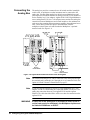
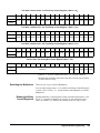
Figure 1-8. Agilent E8460A Multiplexer Front Panell Pin-out 3- and 4-Wire Mode
(3-Wire Mode does not use Column E connections)
Configuring the Agilent E8460A Multiplexer
21
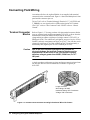
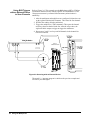
Connecting the
Analog Bus
The analog bus provides a common bus to all switch modules in multiple
switch cards. A multimeter or other instrument can be connected to the
analog bus. Use flat ribbon analog bus cables between Multiplexers and
other Agilent VXI modules that have an analog bus (both C-size modules or
B-size modules in a C-size adapter). Agilent E1411A/B 5-Digit Multimeter
users (and Agilent E1326 in a C-size adapter) must continue the analog bus
connection between Multiplexers and switch modules to the multimeter in
order to use the scanning and measurement capability the multimeter has to
offer. These cables provide the input to the multimeter from the
multiplexer/switch chan- nels and fit under the Multiplexer’s optional
terminal cards. See Figure 1-9.
E8460A
MULTIPLEXERs
HP E8460A
MULTIPLEXER MODULES
Figure 1-9. Agilent E1411A/B Connections to the Analog Bus
22
Note
An external measuring device can be connected to the analog bus through
the terminal card's terminals (pin 5 through pin 16 of connector P109). See
Option 014 Fault Tolerant Terminal Block on page 23.
Note
If you are using the Agilent E1326A/B 5½-Digit Multimeter in a C-size
adapter. Use the 19.5 inch analog bus cable part number E1326-61611 for
analog bus connection between your Agilent E1326 and the Agilent
E8460A. The cable described above will be too short for connection to the
Agilent E1326.
WARNING
If either end of the analog bus is accessible to users (such as
on the front panel of a multimeter), the Multiplexer inputs must
be limited to 30VACrms or 60VDC.
Configuring the Agilent E8460A Multiplexer
Terminal Cards
Three optional terminal cards are available for the Agilent E8460A:
• Option 012 Crimp and Insert Terminal Card
• Option 014 Fault Tolerant Terminal Card
• Option 015 Ribbon Cable Connector Terminal Card
Option 012
Crimp-and-Insert
Terminal Block
Note
The Option 012 Terminal Block provides a terminal card housing and two
160-pin terminal connector blocks (Agilent P/N 1252-6531) but no contacts.
The contacts for the Option 012 Terminal Block connectors ARE NOT
provided. You must purchase them in addition to the option. This allows
you to purchase only the number of contacts you require for your
application.
Agilent P/N 8150-5207 is available for purchase and is a single-conductor
with contact (a crimp-and-insert contact is crimped onto one end, the other
end is not terminated). Refer to Page 18, "Figure 1-5. Terminal Connector
Block and Single-Conductor Wire with Contact".
The crimp-and-insert contacts you must purchase (Agilent P/N 1252-6533
for single contact) are gold-plated, accept a wire size of 20 to 26AWG, and
carry a maximum current of 2A @70°C. You will also need a crimp tool
(Agilent P/N 8710-2306 or ERNI Components P/N 014374) and optionally
a disassembly tool (Agilent P/N 8710-2307 or ERNI Components P/N
471555).
Caution
Due to the close terminal spacing and the potential for
pin-to-pin leakage, the terminal connector blocks on the Agilent
E8460A Option 012 Crimp and Insert Terminal Card must be
replaced after 10,000 hours of use if the module regularly
switches voltages greater than 60VDC, 50VACrms, or 70.7
VACpeak.
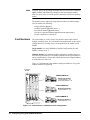
Option 014
Fault Tolerant
Terminal Block
Option 014 Terminal Block provides nine ribbon-cable header connectors.
P101 through P108 provide the channels and terminal bus connection from
the front panel connectors (J101 and J102) of the Agilent E8462A; P109 is
a 16-pin connector for the analog bus connection. DS101 and DS102 are
LEDs which provide information as follows. The green LED (DS101) will
light as the Multiplexer is accessed by the VXI controller. The yellow LED
(DS102) monitors the firmware execution, and will light whenever there is
error during DIAG:TEST? or *TST? command execution.
Caution
The Option 014 Fault Tolerant Terminal Card is limited 60VDC
or 50 VACrms or 70.7 VACpeak maximum. Do not exceed these
voltages.
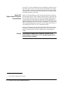
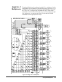
Figure 1-10 shows the associated channel numbers. RT100 through RT355
Configuring the Agilent E8460A Multiplexer
23
are 256 PTC1 resistors which behave like a resettable fuse and will increase
impedance when excessive current is flowing in the channel. For example,
if the contacts of one relay are welded together because it switches a large
voltage, the PTC resistors help protect user circuitry on other channels in the
same bank when their relays close.
Option 015
Ribbon Cable Connector
Terminal Block
Option 015 Terminal Block provides nine ribbon-cable header connectors.
P101 through P108 provide the channels and terminal bus connection from
the front panel connectors (J101 and J102) of the Agilent E8462A; P109 is
a 16-pin connector for the analog bus connection. DS101 and DS102 are
LEDs which provide information as follows. The green LED (DS101) will
light as the Multiplexer is accessed by the VXI controller. The yellow LED
(DS102) monitors the firmware execution, and will light whenever there is
error during DIAG:TEST? or *TST? command execution.
Option 015 is identical to option 014 except the PTC fault tolerant resistors
are replaced with shorts. This terminal block only provides a convenient
means to connect the field wiring, via ribbon cable, to the multiplexer
module.
Caution
The Option 015 Ribbon Cable Connector Terminal Card is
limited 60VDC or 50 VACrms or 70.7 VACpeak maximum. Do
not exceed these voltages.
1. PTC: Positive Temperature Coefficient.
24
Configuring the Agilent E8460A Multiplexer
J3
J4
C ONNEC T TO J10
J 1 (E84 60 A)
P10 1
2
2
P10 3
2
1
P10 2
2
2
P1 04
2
16
15
1
2
H1
L1
G
H2
L2
G
NC
NC
Green
LED
DS101
1
Te r0
2
A1 CH000
CH001
1
1
Te r2
2
B1 C H032
B2
B31
B32
33
CH063
Te r1
34
Te r8
1
2
A1 CH128
P101 - 34
Te r3
34
P105 - 1
Te r10
1
B1 C H160
2
P105 -2
CH129
3
B2
B31
33
B32
Te r9
34
P106 -1
Te r12
1
D1 CH192
2
34
P105 - 34
Te r11
P104 - 33
RT227
P103 -34
Te r7
34
P107 -1
Te r14
1
E1 CH224
2
P107 - 2
E2
D31
E31
P106 -34
32
CH254
Te r13
P108 - 32
RT354
E32
33
CH255
P107 - 33
RT323
P108 - 2
P108 - 3
P107 - 32
33
D32 CH223
P108 -1
RT325
32
CH222
P104 -34
3
CH225
P107 - 3
RT322
34
33
CH127
RT324
P106 - 33
RT291
E32
3
D2 CH193
33
CH191
P105 -33
RT259
Te r5
P106 - 3
P104 - 32
RT226
P102 -34
RT290
RT258
A32 CH159
RT195
P106 - 32
32
CH126
RT293
32
C H190
P105 -32
E31
P103 - 33
RT261
32
CH158
3
C H161
P104 - 3
P103 - 32
33
D32 CH095
P106 - 2
3
CH097
RT292
P105 -3
RT229
A31
32
CH094
RT260
RT228
A2
D31
P104 - 2
RT197
P102 - 33
RT163
E2
P103 - 3
RT194
P101 -33
RT131
P102 - 32
2
E1 CH096
P104 -1
RT196
3
D2 CH065
P102 - 3
RT162
33
P103 - 2
1
Te r6
P103 -1
RT165
32
C H062
P101 -32
2
D1 CH064
RT133
RT130
A32 CH031
P102 - 2
1
Te r4
P102 -1
RT164
3
C H033
RT101
32
P108
2
RT132
3
CH030
1
1
P101 -3
A31
P106
Yellow
LED
DS102
RT100
A2
P1 07
2
1
P101 - 1
P101 -2
P105
1
1
1
P109
C ONNEC T TO J1 02 (E84 6 0A)
34
P104 - 33
RT355
P107 -34
Te r15
34
P108 -34
Figure 1-10. Agilent E8460A Option 014 Fault Tolerant Terminal Card Connectors Pin-out
Configuring the Agilent E8460A Multiplexer
25
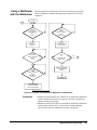
Wiring a Terminal Card
Figure 1-11 shows how to wire the optional terminal cards.
Figure 1-11. Wiring a Terminal Card
26
Configuring the Agilent E8460A Multiplexer
See Figure 1-12 for more
information.
Mark the last
digit of the MUX
model number
e.g., E8460
Figure 1-11. Wiring a Terminal Card (continued)
Configuring the Agilent E8460A Multiplexer
27
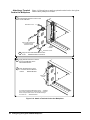
Attaching a Terminal
Card to the Multiplexer
1
Figure 1-12 shows how to attach an optional terminal card to the Agilent
E8460A Relay Multiplexer module.
Extend the Extraction Levers on the
Terminal Module
Extraction Lever
Use a small screwdriver
to release the two
extraction levers
HP E8460A
MODULE
Extraction Lever
2
Align the Terminal Module Connectors
to the HP E8460A Module Connectors
3
Apply Gentle Pressure to Attach
the Terminal Module to the
HP E8460A Module
4
Push the Extraction Levers
to Lock the Terminal Module
onto the HP E8460A Module
Extraction
Levers
To remove the Terminal Module from the HP E8460A,
use a small screwdriver to release the two extraction
levers and push both levers out simultaneously to
fre it from the HP E8460A M odule
Figure 1-12. Attach a Terminal Card to the Multiplexer
28
Configuring the Agilent E8460A Multiplexer
Programming the Multiplexer
To program the Agilent E8460A Multiplexer using SCPI, you must know
the interface and module address and SCPI commands to be used.
Guidelines to select SCPI commands for the Multiplexer follow. See the
Agilent 75000 Series C Installation and Getting Started Guide for interface
addressing.
Note
Specifying SCPI
Commands
Channel Address
This discussion applies only to SCPI (Standard Commands for
Programmable Instruments) programming. See Appendix B for
information on the Multiplexer's registers.
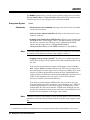
To address specific channels within a Multiplexer, you must specify the
SCPI command and channel address. Use CLOSe <channel_list> to close
the channels specified, OPEN <channel_list> to open the channels
specified, and SCAN <channel_list> to close and open the set of channels
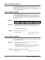
specified, one channel at a time.
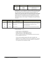
The Multiplexer's channel address (channel_list) has the form (@ccnnn)
where cc = module (card) number (01-99) and nnn = channel numbers. The
channel number consists of three parts listed in the below table:
Channel List
Card Number
(cc)
ccnnn
Channel Number
(nnn)
Channel Description
000-255
256 channel relays
300-347
48 tree relays
990-994
5 analog bus relays
01-99
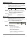
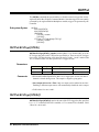
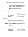
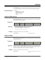
The tree relays and analog bus relays have the same channel number no
matter what operating mode the Multiplexer is. But the channel relays
(CH000-255) may have different channel numbers under different operating
mode. See the following table:
Operating Mode
Valid Channel
Number
Corresponds to 1-Wire Mode Channel
1-wire
000-255
000-255
2-wire
000-127
000-031, 064-095, 128-159, 192-223
(Channel 000 is paired with channel 032, 001
is paired with 033, etc. Channel 064 is paired
with 096, 065 with 097, etc. Channel 128 is
paired with 160, channel 129 with 161, etc.
Channel 192 is paired with 224, channel 193
with 225, etc.)
3-wire
000-063
000-031, 128-159
4-wire
000-063
000-031, 128-159
Refer to Chapter 3 of this Manual, the command [ROUTe:]CLOSe for the
paired channel information.
Configuring the Agilent E8460A Multiplexer
29
Note
You must specify the operating mode BEFORE you execute the commands
OPEN, CLOSe, and SCAN. Pay attention to the valid channel numbers
when you open, close or scan the specific channel(s) in different operating
modes.
The channels can be addressed using channel numbers or channel ranges.
You can address the following:
• single channels (@ccnnn);
• multiple channels (@ccnnn,ccnnn,...);
• sequential channels (@ccnnn:ccnnn);
• groups of sequential channels (@ccnnn:ccnnn,ccnnn:ccnnn);
• or any combination of the above.
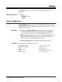
Card Numbers
The card number (cc of the channel list) identifies the module within a
multiple switching cards. The card number assigned depends on the switch
configuration used. Leading zeroes can be ignored for the module (card)
number.
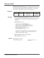
Single-module. In a single Multiplexer module configuration, the card
number is always 01 or 1.
Multiple-module. In a multiple-module configuration, modules are set to
successive logical addresses. The module with the lowest logical address is
always card number 01. The module with the next successive logical address
is card number 02, and so on.
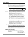
Figure 1-13 illustrates the card numbers and logical addresses of a typical
multiple-module configuration.
Command
Module
CARD NUMBER 01
Multiplexer Number 1
Logical Address = 112
Secondary Address = 14
CARD NUMBER 02
Multiplexer Number 2
Logical Address = 113
CARD NUMBER 03
Multiplexer Number 3
Logical Address = 114
Figure 1-13. Card Numbers in a Multiple-module Configuration
30
Configuring the Agilent E8460A Multiplexer
Channel Numbers,
Ranges, and Lists
Note
The Agilent E8460A Multiplexer channel numbers are 000 through 255
under the 1-wire mode. The channels can be addressed using individual
channel numbers or channel ranges.
For all other modes, the “channel” is actually used to refer to the paired
channel. Under 2-wire mode, there are 128 2-wire paired channels, under
3-wire and 4-wire modes, there are only 64 paired 3-wire or 4-wire
channels. See Chapters 2 and 3 for more information of paired channels.
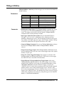
Use commas (,) to form a channel list or use a colon (:) to form a channel
range. Only valid channels can be accessed in a channel list or channel
range. Also, the channel list or channel range must be from a lower channel
number to a higher channel number. For example, CLOS(@1000:1015) is
acceptable, but CLOS(@1015:1000) generates an error.
Using the channel range (@nn000:nn999) with the SCAN command causes
all channels to be scanned except the tree relays (CH300-347). These are not
typical scan channels and therefore are not included in a scan list.
Below are some SCPI commands and a description of their effect on channel
lists and ranges.
Channel Lists:
FUNC 1, WIRE2
CLOS(@1000,1001)
OPEN(@1003,1010)
Set the module to 2-wire mode.
Close paired channels 000 and
001 on card #1 (channels 0, 1,
32 & 33 will be closed together).
Open paired channels 03 and 10
on card #1.
Channel Ranges:
FUNC 1, WIRE1
OPEN (@1000:1255)
CLOS (@1000,1127)
SCAN (@1128:1255)
Set the module to 1-wire mode.
Open all channels on card #1.
Close channels 000 and 127 on
card #1.
Define channels 128-255 to be
scanned.
Configuring the Agilent E8460A Multiplexer
31
Initial Operation
You must download the Agilent E8460A SCPI driver into the
Agilent E1405/E1406 Command Module to perform the initial operation.
At power-on or following a reset of the module (*RST command), all 256
channels are open. A *RST command invalidates the current scan list (that
is, you must specify a new scan list). Command parameters are set to the
default conditions as shown below.
Parameter
Default
Value
Description
ARM:COUNt
1
Number of scanning cycles is one.
TRIGger:SOURce
IMM
Advances through a scanning list
automatically.
INITiate:CONTinuous
OFF.
Continuous scanning disabled.
OUTPut[:STATe]
OFF
Trigger output from EXT, TTL, or ECL
sources is disabled.
[ROUTe:]FUNC
NONE
Operating mode is set to NONE. You must
always set the mode after power-on or reset
the module.
[ROUTe:]SCAN:MODE
NONE
Channel list is not set up.
[ROUTe:]SCAN:PORT
NONE
Analog bus connections are disabled from
channels.
Execute SCAN:PORT ABUS to enable use of the analog bus for the SCAN
command. A CLOSe command requires that you also close the appropriate
tree relay to make connection to the analog bus (see Page 13 "Figure 1-1.
Agilent E8460A Simplified Schematic" ).
Note
Do not do register writes if you are controlling the module by a high level
driver such as SCPI or VXIplug&play. This is because the driver will not
know the module state and an interrupt may occur causing the driver and/or
command module to fail.
The following example program was developed with the ANSI C language
using the Agilent VISA extensions. The program was written and tested in
Microsoft® Visual C++ but should compile under any standard ANSI C
compiler.
To run the program you must have the Agilent SICL Library, the Agilent
VISA extensions, and an Agilent 82340 or 82341 GPIB module installed
and properly configured in your PC. An Agilent E1406 Command Module
is required.
32
Configuring the Agilent E8460A Multiplexer
Example: Reset,
Self Test, Module
ID, and Close
Channel
The following example reads the module ID string, performs module
self-test, displays the results, closes channel 002 and queries the channel
closure state. The result is returned to the computer and displayed
(“1” = channel closed, “0” = channel open).
#include <visa.h>
#include <stdio.h>
#include <stdlib.h>
/* Module Logical address is 112, secondary address is 14*/
#define INSTR_ADDR “GPIB0::9::14::INSTR”
int main()
{
ViStatus errStatus;
ViSession viRM;
ViSession E8460A;
char id_string[256];
char selftst_string[256];
char ch_state;
/*Status from each VISA call*/
/*Resource mgr. session */
/* Module session */
/*ID string*/
/*self-test string*/
/*channel open/close state*/
/* Open the default resource manager */
errStatus = viOpenDefaultRM ( &viRM);
if(VI_SUCCESS > errStatus){
printf(“ERROR: viOpenDefaultRM() returned 0x%x\n”,errStatus);
return errStatus;}
/* Open the Module instrument session */
errStatus = viOpen(viRM,INSTR_ADDR, VI_NULL,VI_NULL,&E8460A);
if(VI_SUCCESS > errStatus){
printf(“ERROR: viOpen() returned 0x%x\n”,errStatus);
return errStatus;}
/* Reset the Module */
errStatus = viPrintf(E8460A, “*RST;*CLS\n”);
if(VI_SUCCESS > errStatus){
printf(“ERROR: viPrintf() returned 0x%x\n”,errStatus);
return errStatus;}
/* Perform Module Self-Test */
errStatus = viQueryf(E8460A,”DIAG:TEST?\n”,”%t”,selftst_string);
if (VI_SUCCESS > errStatus) {
printf(“ERROR: viQueryf() returned 0x%x\n”,errStatus);
return errStatus;}
printf(“Self Test Result is %s\n”,selftst_string);
/* Query the Module ID string */
errStatus = viQueryf(E8460A,”*IDN?\n”,”%t”,id_string);
if (VI_SUCCESS > errStatus) {
printf(“ERROR: viQueryf() returned 0x%x\n”,errStatus);
return errStatus;}
printf(“ID is %s\n”,id_string);
Configuring the Agilent E8460A Multiplexer
33
/* Close Channel 002 */
errStatus = viPrintf(E8460A, “FUNC 1,WIRE1;CLOS (@1002)\n”);
if(VI_SUCCESS > errStatus){
printf(“ERROR: viPrintf() returned 0x%x\n”,errStatus);
return errStatus;}
/* Query State of Channel 002 */
errStatus = viQueryf(E8460A,”ROUT:CLOS? (@1002)\n”,”%t”,ch_state);
if (VI_SUCCESS > errStatus) {
printf(“ERROR: viQueryf() returned 0x%x\n”,errStatus);
return errStatus;}
printf(“Channel State is: %s\n”,ch_state);
/* Open Channel 002 */
errStatus = viPrintf(E8460A, “OPEN (@1002)\n”);
if(VI_SUCCESS > errStatus){
printf(“ERROR: viPrintf() returned 0x%x\n”,errStatus);
return errStatus;}
/* Close the Module Instrument Session */
errStatus = viClose (E8460A);
if (VI_SUCCESS > errStatus) {
printf(“ERROR: viClose() returned 0x%x\n”,errStatus);
return 0;}
/* Close the Resource Manager Session */
errStatus = viClose (viRM);
if (VI_SUCCESS > errStatus) {
printf(“ERROR: viClose() returned 0x%x\n”,errStatus);
return 0;}
return VI_SUCCESS;
}
34
Configuring the Agilent E8460A Multiplexer
Chapter 2
Using the Multiplexer
What’s in This Chapter
This chapter shows how to use the Agilent E8460A 256-Channel
Multiplexer module. The chapter contains the following sections:
• Reset Conditions . . . . . . . . . . . . . . . . . . . . . . . . . . . . . . . . . .
• Switching or Scanning . . . . . . . . . . . . . . . . . . . . . . . . . . . . .
• Scanning Channels Using the Analog Bus . . . . . . . . . . . . . .
• Recalling and Saving States . . . . . . . . . . . . . . . . . . . . . . . . .
• Detecting Error Conditions . . . . . . . . . . . . . . . . . . . . . . . . . .
Page 35
Page 36
Page 43
Page 53
Page 54
Reset Conditions
At power-on or following the reset of the module (*RST command), all 256
channel relays, 48 tree relays, and five analog bus connection relays are
open. In addition, after a *RST command, the scan channel list is empty.
Table 2-1 lists the parameters and default values for the functions following
turn-on or reset.
Table 2-1. Agilent E8460A Default Conditions for Power-on and Reset
Parameter
ARM:COUNt
Default
Value
Description
1
Number of scanning cycles is one.
TRIGger:SOURce
IMM
Advances through a scanning list
automatically.
INITiate:CONTinuous
OFF
Continuous scanning disabled.
OUTPut[:STATe]
OFF
Trigger output from EXT, TTL, or ECL
sources is disabled.
[ROUTe:]SCAN:MODE
NONE
Channel list is not set up.
[ROUTe:]SCAN:PORT
NONE
Analog bus connections are disabled.
Channel state
All 256 channels are open (CH000-255 are open).
Tree relays state
All the 48 tree relays are open (CH300-347 are open).
Analog bus connection relay status
5 analog bus relays are open (CH990-994 are open).
Channel list from SCAN command
(after *RST)
Channel list is empty following a reset of the module
with *RST command.
Using the Multiplexer
35
Switching or Scanning
There are two general ways to use the Agilent E8460A Relay Multiplexer.
First, you can use the ROUTe:FUNCTion command subsystem (see Chapter
3) to set up the multiplexer in any of its four operating modes: 1-Wire,
2-Wire, 3-Wire, or 4-Wire Mode. You can then use the ROUTe:CLOSe or
ROUTe:OPEN commands to control individual channel relays. In the
2-Wire, 3-Wire, and 4-Wire modes, banks of channels are paired together
such that when you close one channel the paired relay(s) also close
automatically. The ROUTe command subsystem automatically closes the
appropriate tree relays depending on the multiplexer mode.
Alternately, you can set the multiplexer mode and scan through a list of
channels. Scanning involves sequentially closing/opening channels in a
channel list. Use the ROUTe:SCAN command to set the scan mode, use the
analog bus, and specify the channel in the channel list.
The channel list used in the ROUTe command subsystem includes the 256
channel relays (CH000-255). Valid channel numbers depend on the
specified mode. The 48 tree relays (CH300-347), and 5 analog bus
connection control relays (CH990-994) are automatically set depending on
the specified mode.
Note
You must specify the Multiplexer’s operating mode before executing the
ROUTe:CLOSe, OPEN, or SCAN functions. These three commands
CANNOT open/close the tree relays (CH300-347). The tree relays can be
only configured either by [ROUTe:]FUNCtion or by command
DIAGnostic:CLOSe. See Chapter 3 for more details. Also, Figure 1-6,
Figure 1-7, and Figure 1-8 shows the valid channel and front panel
connections for the various modes.
Note
Pay special attention to the valid channel numbers when you execute these
SCPI commands. Refer to the comments of the ROUTe subsystem
commands in Chapter 3 for more information of the paired channel and
valid channel numbers.
Switching Channels
to the Analog Bus
Measurements can be done through either the analog bus or the terminal bus
(Ter0-Ter15). When the multiplexer mode is specified, the appropriate tree
relays are automatically closed connecting banks to the appropriate terminal
bus. To use the analog bus, however, you must execute the
ROUTe:SCAN:PORT command. Once closed, tree relays remain closed
until specifically opened (DIAG:OPEN command, power removed from the
module, or module reset with a *RST command).
36
Using the Multiplexer
Performing
Measurements via
Analog Bus
To perform measurements via analog bus, you need to either manually close
the analog bus connection control relays (CH990-994) through command
ROUTe:CLOSe or execute the command ROUTe:SCAN:PORT ABUS.
1-wire, 2-wire, 3-wire and 4-wire measurements can be done via analog bus
by connecting CH990-994. These modes are described in more detail later
in this chapter.
1-Wire Mode:
All the 256 channel relays are connected to Ter0 and
connected to analog bus H1 through closing T49
(CH990). Valid channel numbers are 000 through 255.
2-Wire Mode:
The 256 channel relays form 128 2-wire pairs which are
connected to Ter0 and Ter2 Terminal buses. Through
closing T49 and T50 (CH990-991), the specific channel
pair is connected to analog bus H1 and L1 to perform
2-wire measurements such as voltage, current and
2-wire resistance measurements. Valid channel
numbers are 000 through 127. From the perspective of
the 1-Wire mode, channel 000 becomes channel 000
Hi, channel 032 becomes channel 000 LO, etc. Refer to
Figure 1-7.
3-Wire Mode:
The 256 channel relays form 64 3-wire pairs which
connect to H1, L1 and L2 through closing T49, T50,
and T53 (CH990, 991 and 994) respectively. The 64
3-wire pairs are: Banks 0/2/4, 1/3/5, 8/10/12 and
9/11/13. Banks 6, 7, 14, 15 are not used. Valid channel
numbers are 000 through 063. From the perspective of
the 1-wire mode, channl 000 becomes channel 000 HI,
channel 032 becomes channel 000 LO1, and channel
064 becomes channel 000 LO2.
4-Wire Mode:
The 256 channel relays form 64 4-wire pairs which
connect to H1, L1, H2, and L2 by closing T49, T50,
T51, and T53 (CH990, 991, 992, 994). In this mode the
4-wire pairs are: Banks 0/2/4/6, 1/3/5/7, 8/10/12/14 and
9/11/13/15. Valid channel numbers are 000 through
063. From the perspective of the 1-wire mode, channl
000 becomes channel 000 HI1, channel 032 becomes
channel 000 LO1, channel 064 becomes channel 000
LO2, and channel 096 becomes channel 000 HI2.
Refer to "Figure 2-1. Channel Switching to the Analog Bus" on page 38. It
shows the connections of the related tree relays in the 4-wire mode. The
analog bus connection control relays are closed to connect specific 4-wire
pairs to analog bus H1, L1, H2, and L2. In this mode the 4-wire pairs are:
Banks 0/2/4/6, 1/3/5/7, 8/10/12/14 and 9/11/13/15. The valid channel
numbers that can be closed/opened/scanned are 000 through 63.
Refer to Chapter 3, ROUTe command subsystem for more information on
valid channel numbers and paired channels under different operating modes.
Using the Multiplexer
37
.
Figure 2-1. Channel Switching to the Analog Bus
38
Using the Multiplexer
1-Wire Mode
In its 1-Wire mode, the Agilent E8460A is configured as a 1 x 256
multiplexer. In this mode, T1 through T16 are closed to connect the specific
channels to Terminal Bus Ter0. The valid channel list to be
opened/closed/scanned includes all 256 channels (000-255). All the
channels can be also connected to H1 by closing T49 (CH990). Figure 2-2
shows 1-Wire operating mode. The following SCPI command example
demonstrates how to set the mode and close a channel.
FUNC 1, WIRE1
CLOS (@1005)
Specify the 1-Wire mode.
Close channel 5.
Figure 2-2. 1-Wire (1 x 256 Multiplexer) Operating Mode
Using the Multiplexer
39
2-Wire Mode
Refer to Figure 2-3. In the 2-Wire mode, all 256 channels form 128 2-wire
pairs which connect to Terminal Bus Ter0 and Ter2. The valid channel
numbers are 000-127. The 128 2-wire pairs are: Banks 0/2, 1/3, 4/6, 5/7,
8/10, 9/11, 12/14 and 13/15. You can also make the 2-wire measurement via
the analog bus (H1 and L1), where you must close the tree relays T49 and
T50 (CH990, 991). The following example shows how to make 2-wire
measurement with a paired channel (CH000 and CH032).
FUNC 1, WIRE2
CLOS (@1000)
Specify 2-wire Mode.
Close paired Ch000 and Ch032
to H1
to L1
to H1
to L1
to H1
to L1
to H1
to L1
Figure 2-3. 2-Wire Operating Mode
40
Using the Multiplexer
3-Wire and
4-Wire Modes
The same basic configuration is used for both the 3-Wire and the 4-Wire
modes. Refer to Figure 2-4. In the 3-Wire mode, relays 0-31 and 128-159
switch to terminal bus Ter0, relays 32-63 and 160-191 switch to Ter2, and
relays 64-95 and 192-223 switch to Ter4. In the 4-Wire mode, relays 0-31
and 128-159 switch to terminal bus Ter0, relays 32-63 and 160-191 switch
to Ter2, relays 64-95 and 192-223 switch to Ter4 and relays 96-127 and
224-255 switch to Ter6.
In either mode the 256 channels will form 64 wire pairs. The valid channel
numbers are 000 through 63. Measurements can be done either through the
four terminal bus Terminals 0, 2, 4, and 6 or through the analog bus by
closing the analog bus relays T49, T50, T51, and T53 (CH990, 991, 992,
994).
For 4-Wire measurements, you would typically use a pair of channels from
banks 0 and 2 for the voltage sense and another pair of channels from banks
4 and 6 for the current source, these four channels forms one 4-wire pair.
Closing any channel in the pair automatically closes the other channel in the
pair. The following SCPI example shows how to set the 4-Wire mode and
how to close the paired channels.
FUNC 1, WIRE4
CLOS (@1000)
Configure 4-wire mode.
Close channel 000. Channels
032, 064, 096 are 4-wire pair
and will close automatically.
Other Modes
The E8460A can also be configured as eight 32X1 multiplexers or sixteen
16X1 multiplexers. There are no commands to automatically set these
modes; if you want to configure the sixteen 16x1 multiplexers, you must use
the DIAG:CLOSe and DIAG:OPEN command to set the appropriate tree
relays.
Caution
When executing DIAGnostic:CLOSe, the specified channel(s)
will close without any checking by the firmware. To prevent
unexpected short circuits or other undesirable results, be very
careful when specifying which channel is to be closed.
Maximum Relay
Closures
Using the DIAG:CLOSe command, it is possible to exceed the maximum
specified current draw of the module. If all 309 relays are closed (at 10mA
per relay) plus the additional current draw from the digital logic circuits; the
maximum possible current draw is 3.2 Amps from the +5 VDC supply. The
module specification (refer to Appendix A) is for one-half of the relays
closed resulting in a 1.7A current draw.
To limit the number of relays closing at any instant, the driver will limit the
number of relay closures to 36, limiting the dynamic current draw to 360 mA
(specification is 400 mA). If you specify more than 36 channels in the
DIAG:CLOSe command, the driver will close the first 36, wait 0.5mS for
closure to complete, close the next 36 channels, wait 0.5mS, close the next
36 channels, wait 0.5 mS, and so on.
Using the Multiplexer
41
to H1
to L1
to L2
to H2
to H1
to L1
to L2
to H2
Figure 2-4. 3-Wire and 4-wire Operating Mode
42
Using the Multiplexer
Eight 32 x 1
Multiplexers
The Agilent E8460A can be configured as eight 32 x 1 multiplexers. In this
configuration, the 256 channels are divided into 8 groups, each one is a 32 x
1 multiplexer. The 8 groups are connected to eight terminal bus (Terminals
0, 2, 4, 6, 8, 10, 12, 14) by closing 16 related tree relays. There are no
commands to automatically set this mode; if you want to configure the eight
32x1 multiplexers, you must use the DIAG:CLOSe and DIAG:OPEN
commands to set the appropriate tree relays.
Figure 2-5. Eight 32 x 1 Multiplexer
Using the Multiplexer
43
Sixteen 16 x 1
Multiplexers
When this switching module is configured as sixteen 16 x 1 Multiplexer, the
16 closed tree relays (T1, T17-18, T20-21, T25-26, T28-29, T37-38,
T40-41, T45-46, T48) will separate all the 256 channels into 16 groups and
connect the specific group channel(s) to the related terminal(s). There are no
commands to automatically set this mode; if you want to configure the
sixteen 16x1 multiplexers, you must use the DIAG:CLOSe and
DIAG:OPEN command to set the appropriate tree relays.
Figure 2-6. Sixteen 16 x 1 Multiplexer
44
Using the Multiplexer
Scanning Channels
Scanning the Multiplexer channels consists of sequentially closing a channel
(and its associated tree relays), making some measurement , opening that
channel, and then repeating that process with the next channel in a channel
list. You can make a single scan through the channel list or scan a multiple
number of times. You can also scan the channel list continuously until the
scan is aborted.
The TRIGger:SOURce command specifies the source to advance the scan.
The OUTPut command can be used to enable the E1406A Command
Module's “Trig Out” port, TTL Trigger bus line (0-7) or ECL Trigger bus
lines (0-1). Figure 2-7 illustrates the commands in the scanning sequence.
ARM:COUN <number>
TRIG:SOUR BUS|HOLD|EXT|
IMM|TTLT|ECLT
OUTP[:EXT] 1|0|ON|OFF
OUTP:ECLT 1|0|ON|OFF
OUTP:TTLT 1|0|ON|OFF
INIT:CONT 1|0|ON|OFF
SCAN:MODE
NONE|VOLT|RES|FRES
SCAN:PORT ABUS
SCAN <channel_list>
INIT
TRIG
Figure 2-7. Command Sequence for Scanning Channels
Using the Multiplexer
45
You can scan a channel or a list of channels using the SCAN command. The
analog bus connection control relays (CH990-994) are automatically closed
when you specify the command SCAN:PORT ABUS. This command is
required for the analog bus control relays to function during the scan through
the channel list. The default value is SCAN:PORT NONE which does not
allow these relays to operate and connect channels to the analog bus.
At power-on or after resetting the module with the *RST command,
connection to the analog bus is disabled for scan operations. You must
execute the command SCAN:PORT ABUS to enable analog bus connection
control relay operation. Access is through the front panel analog bus
connector (usually connected to other multiplexers or to the E1411A/B
multimeter) or through the terminal module (Opt 014) “VM Input” and “I”
terminals on P109 connector (see Figure 1-1 on page 13).
Synchronizing the
Multiplexer with a
Multimeter
Measurement Set-Up
This example uses the TTL VXIbus triggers (TTLT 0-7) to synchronize
channel closures with the Agilent E1412A 6-Digit Multimeter. DC Voltage
measurements are performed. Measurement synchronization is attained
bythe multimeter sending a voltmeter complete signal on TT Trigger Line 1
and receiving the channel closed signal on TTL Trigger Line 0. Similarly,
the multiplexer module sends its channel closed signal on TTL 0 and
receives its channel advance signal on TTL 1. Note; Figure 2-8 shows
connections between the Agilent E1406A Command Module Trigger In and
Trigger Out to the Agilent E1412A Trigger In and Voltmeter Complete. This
simply demonstrates an alternate method of synchronizing the
measurements.
• Agilent E1412A has an GPIB select code = 7, primary address = 09
and secondary address = 03.
• Agilent E8460A has an GPIB select code = 7, primary address = 09
and secondary address = 14.
• Controller is an IBM compatible PC, the programming language is
Visual C/C++ with Agilent VISA extensions.
46
Using the Multiplexer
HP E8460A
Multiplexers
HP E8460A
Terminal Module
HP E8460A
Multiplexers
Figure 2-8. Scanning with VXIbus Triggers
The following example program was developed with the ANSI C language
using the Agilent VISA extensions. The program was written and tested in
Microsoft® Visual C++ but should compile under any standard ANSI C
compiler.
To run the program you must have the Agilent SICL Library, the Agilent
VISA extensions, and an Agilent 82340 or 82341 GPIB module installed
and properly configured in your PC. An Agilent E1406 Command Module
is required.
This following example resets and configures the multimeter for DC
Voltage measurements, resets and configures the multiplexer for 2-Wire
configuration TTL Trigger bus synchronization, use of the analog bus, and
scanning channels 00 through 09.
#include <visa.h>
#include <stdio.h>
#include <stdlib.h>
/* Interface address is 112, Module secondary address is 14*/
#define INSTR_ADDR “GPIB0::9::14::INSTR”
/* interface address for Agilent E1412 Multimeter */
#define MULTI_ADDR “GPIB0::9::3::INSTR”
Using the Multiplexer
47
int main()
{
ViStatus errStatus;
/*Status from each VISA call*/
ViSession viRM;
/*Resource mgr. session */
ViSession E8460A;
/* Module session */
ViSession E1412A;
/* Multimeter session */
viSetAttribute (E1412A,VI_ATTR_TMO_VALUE,268435456)
/* multimeter timeout value */
int ii;
/* loop counter */
char opc_int[21]
/* OPC? variable */
double readings [10];
/* Reading Storage*/
/* Open the default resource manager */
errStatus = viOpenDefaultRM ( &viRM);
if(VI_SUCCESS > errStatus){
printf(“ERROR: viOpenDefaultRM() returned 0x%x\n”,errStatus);
return errStatus;}
/* Open the Module instrument session */
errStatus = viOpen(viRM,INSTR_ADDR, VI_NULL,VI_NULL,&E8460A);
if(VI_SUCCESS > errStatus){
printf(“ERROR: viOpen() returned 0x%x\n”,errStatus);
return errStatus;}
/* Open the Multimeter instrument session */
errStatus = viOpen(viRM,MULTI_ADDR, VI_NULL,VI_NULL,&E1412A);
if(VI_SUCCESS > errStatus){
printf(“ERROR: viOpen() returned 0x%x\n”,errStatus);
return errStatus;}
/* Reset the Multimeter, clear status system */
errStatus = viPrintf(E1412A, “*RST;*CLS\n”);
if(VI_SUCCESS > errStatus){
printf(“ERROR: viPrintf() returned 0x%x\n”,errStatus);
return errStatus;}
/*Configure Multimeter for DCV measurements, 12 V max, min resolution */
errStatus = viPrintf(E1412A, “CONF:VOLT 12,MIN\n”);
if(VI_SUCCESS > errStatus){
printf(“ERROR: viPrintf() returned 0x%x\n”,errStatus);
return errStatus;}
/* Set multimeter trig input TTLT0 Trigger Line */
errStatus = viPrintf(E1412A, “TRIG:SOUR:TTLT0\n”);
if(VI_SUCCESS > errStatus){
printf(“ERROR: viPrintf() returned 0x%x\n”,errStatus);
return errStatus;}
/* Enable Measurement Complete on TTL2 */
errStatus = viPrintf(E1412A, “OUTP:TTLT1 ON\n”);
if(VI_SUCCESS > errStatus){
printf(“ERROR: viPrintf() returned 0x%x\n”,errStatus);
return errStatus;}
48
Using the Multiplexer
/* Enable Trigger Delay */
errStatus = viPrintf(E1412A, “TRIG:DEL 0.001\n”);
if(VI_SUCCESS > errStatus){
printf(“ERROR: viPrintf() returned 0x%x\n”,errStatus);
return errStatus;}
/* Set Multimeter for 10 triggers */
errStatus = viPrintf(E1412A, “TRIG:COUN 10\n”);
if(VI_SUCCESS > errStatus){
printf(“ERROR: viPrintf() returned 0x%x\n”,errStatus);
return errStatus;}
/* Pause until multimeter is ready */
errStatus = viQueryf(E1412A, “*OPC?\n”,”%t”,opc_int);
if(VI_SUCCESS > errStatus){
printf(“ERROR: viQueryf() returned 0x%x\n”,errStatus);
return errStatus;}
/* Initialize Multimeter, wait for trigger */
errStatus = viPrintf(E1412A, “INIT\n”);
if(VI_SUCCESS > errStatus){
printf(“ERROR: viPrintf() returned 0x%x\n”,errStatus);
return errStatus;}
/* Reset E8460A */
errStatus = viPrintf(E8460A,”*RST;*CLS\n”);
if (VI_SUCCESS > errStatus) {
printf(“ERROR: viPrintf() returned 0x%x\n”,errStatus);
return errStatus;}
/* Enable Trigger Output on TTL2 */
errStatus = viPrintf(E8460A, “OUTP:TTLT0 ON\n”);
if(VI_SUCCESS > errStatus){
printf(“ERROR: viPrintf() returned 0x%x\n”,errStatus);
return errStatus;}
/* Set Trigger Input On TTL 1 */
errStatus = viPrintf(E8460A, “TRIG:SOUR TTLT1\n”);
if(VI_SUCCESS > errStatus){
printf(“ERROR: viPrintf() returned 0x%x\n”,errStatus);
return errStatus;}
/* Set Multiplexer to 2-Wire mode */
errStatus = viPrintf(E8460A, “ROUT:FUNC ,WIRE2\n”);
if(VI_SUCCESS > errStatus){
printf(“ERROR: viPrintf() returned 0x%x\n”,errStatus);
return errStatus;}
Using the Multiplexer
49
/* Set Multiplexer to Voltage mode */
errStatus = viPrintf(E8460A, “SCAN:MODE VOLT\n”);
if(VI_SUCCESS > errStatus){
printf(“ERROR: viPrintf() returned 0x%x\n”,errStatus);
return errStatus;}
/* Enable Analog Bus */
errStatus = viPrintf(E8460A, “SCAN:PORT ABUS\n”);
if(VI_SUCCESS > errStatus){
printf(“ERROR: viPrintf() returned 0x%x\n”,errStatus);
return errStatus;}
/* Set Scan List */
errStatus = viPrintf(E8460A, “SCAN(@1000:1009)\n”);
if(VI_SUCCESS > errStatus){
printf(“ERROR: viPrintf() returned 0x%x\n”,errStatus);
return errStatus;}
/* Pause until ready */
errStatus = viQueryf(E8460A, “*OPC?\n”,”%t”,opc_int);
if(VI_SUCCESS > errStatus){
printf(“ERROR: viQueryf() returned 0x%x\n”,errStatus);
return errStatus;}
/* Start Scan */
errStatus = viPrintf(E8460A, “INIT\n”);
if(VI_SUCCESS > errStatus){
printf(“ERROR: viPrintf() returned 0x%x\n”,errStatus);
return errStatus;}
/* Get readings from Multimeter */
errStatus = viQueryf(E1412A, “FETC?\n”,”%,10lf”,readings);
if(VI_SUCCESS > errStatus){
printf(“ERROR: viQueryf() returned 0x%x\n”,errStatus);
return errStatus;}
for (ii=0;ii<10;ii++) {
printf (Reading %d is: %lf\n”,ii,readings[ii]); }
/* Reset E8460A to open all channels*/
errStatus = viPrintf(E8460A,”*RST\n”);
if (VI_SUCCESS > errStatus) {
printf(“ERROR: viPrintf() returned 0x%x\n”,errStatus);
return errStatus;}
/* Close the E8460A Instrument Session */
errStatus = viClose (E8460A);
if (VI_SUCCESS > errStatus) {
printf(“ERROR: viClose() returned 0x%x\n”,errStatus);
return 0;}
50
Using the Multiplexer
/* Close the Multimeter Instrument Session */
errStatus = viClose (E1412A);
if (VI_SUCCESS > errStatus) {
printf(“ERROR: viClose() returned 0x%x\n”,errStatus);
return 0;}
/* Close the Resource Manager Session */
errStatus = viClose (viRM);
if (VI_SUCCESS > errStatus) {
printf(“ERROR: viClose() returned 0x%x\n”,errStatus);
return 0;}
return VI_SUCCESS;
}
Using the Multiplexer
51
Using BUS Triggers
with an External Device
to Scan Channels
Refer to Figure 2-9. This example uses the BUS trigger (GET or *TRG) to
synchronize channel closures with the Agilent 3457A Multimeter. A DC
voltage measurement is performed. Measurement synchronization is
attained by:
1. After the multimeter and multiplexer are configured, iniitate the scan
on the Agilent E8460A (INIT comman). This closes the first channel.
2. FETCH? the reading from the multimeter.
3. Trigger the multiplexer (*TRG command). This opens the channel
and closes the next channel in the list. After the relay settles, the
Agilent E1406A outputs a trigger to trigger the multimeter.
4. Repeat steps 2 and 3 in a loop until all channels in the channel list
have been scanned.
E8460A
TERMINAL MODULE
H
L
G
Figure 2-9. Scanning with an External Device
The actual C++ language program is similar to the previous example and
will not be presented again.
52
Using the Multiplexer
Recalling and Saving States
This section contains information about saving and recalling a Multiplexer
module state.
Saving States
The *SAV <numeric_state> command saves the current instrument state.
The state number (0-9) is specified in the state parameter. The following
settings are saved:
• Channel Relay State (CH000-256 open or closed);
• Tree Relay State (CH300-347 open or closed);
• Analog Bus Connection Control Relay State (CH990-994 open or
closed)
• ARM:COUNt Value
• TRIGger:SOURce Mode
• OUTPut[:STATe] Configuration
• INITiate:CONTinuous Mode
• [ROUTe:]SCAN:MODE Mode
• [ROUTe:]SCAN:PORT Mode
Recalling States
The *RCL <numeric_state> command recalls a previously saved state.
Enter the number (0-9) in the state parameter of the desired saved state. If
*SAV was not previously executed using the selected number, the
Multiplexer will be configured to the reset values (see "Table 2-1. Agilent
E8460A Default Conditions for Power-on and Reset" on page 35).
Note
Scan lists are not saved when a state is saved. You must re-enter your scan
list after recalling a state.
Using the Multiplexer
53
Detecting Error Conditions
There are two general approaches to error checking. The simplest, but most
time consuming, is to ask the instrument whether there are errors at every
step of the switching process. This is called “polling” and is illustrated in the
two previous program examples.
Using Interrupts
With Error
Checking
54
Using the Multiplexer
The second approach involves the use of interrupts. In this approach, the
program monitors the Multiplexer's Standard Event Status Register for an
error condition. If no errors occur, the Multiplexer functions as
programmed. If errors do occur, the Multiplexer interrupts the computer,
and the error codes and messages are read from the error queue.
Chapter 3
Multiplexer Command Reference
Using This Chapter
This chapter describes Standard Commands for Programmable Instruments (SCPI)
and summarizes IEEE 488.2 Common (*) commands applicable to the E8460A
256-Channel Multiplexer Module. This chapter contains the following sections.
• Command Types. . . . . . . . . . . . . . . . . . . . . . . . . . . . . . . . . . . page 55
• SCPI Command Reference . . . . . . . . . . . . . . . . . . . . . . . . . . page 58
• SCPI Command Quick Reference . . . . . . . . . . . . . . . . . . . . . page 89
• IEEE 488.2 Common Command Reference . . . . . . . . . . . . . page 90
Command Types
Commands are separated into two types: IEEE 488.2 Common Commands and SCPI
Commands.
Common
Command
Format
The IEEE 488.2 standard defines the common commands that perform functions
such as reset, self-test, status byte query, and so on. Common commands are four or
five characters in length, always begin with the asterisk character (*), and may
include one or more parameters. The command keyword is separated from the first
parameter by a space character. Some examples of common commands are shown
below:
*RST
SCPI
Command
Format
*ESR 32
*STB?
The SCPI commands perform functions like closing switches, making
measurements, and querying instrument states or retrieving data. A subsystem
command structure is a hierarchical structure that usually consists of a top level (or
root) command, one or more lower level commands, and their parameters. The
following example shows part of a typical subsystem:
[ROUTe:]
CLOSe <channel_list>
SCAN <channel_list>
:MODE?
[ROUTe:] is the root command, CLOSe and SCAN are second level commands with
parameters, and :MODE? is a third level command.
Command
Separator
A colon (:) always separates one command from the next lower level command as
shown below:
ROUTe:SCAN:MODE?
Colons separate the root command from the second level command (ROUTe:SCAN)
and the second level from the third level (SCAN:MODE?).
Multiplexer Command Reference
55
Abbreviated
Commands
The command syntax shows most commands as a mixture of upper and lower case
letters. The upper case letters indicate the abbreviated spelling for the command. For
shorter program lines, send the abbreviated form. For better program readability, you
may send the entire command. The instrument will accept either the abbreviated
form or the entire command.
For example, if the command syntax shows MEASure, then MEAS and MEASURE
are both acceptable forms. Other forms of MEASure, such as MEASU or MEASUR
will generate an error. You may use upper or lower case letters. Therefore,
MEASURE, measure, and MeAsUrE are all acceptable.
Implied
Commands
Implied commands are those which appear in square brackets ([ ]) in the command
syntax. (Note that the brackets are not part of the command and are not sent to the
instrument.) Suppose you send a second level command but do not send the
preceding implied command. In this case, the instrument assumes you intend to use
the implied command and it responds as if you had sent it. Examine the partial
[ROUTe:] subsystem shown below:
[ROUTe:]CLOSe <channel_list>
CLOSe? <channel_list>
OPEN <channel_list>
OPEN? <channel_list>
SCAN <channel_list>
:MODE <mode>
:MODE?
The root command [ROUTe:] is an implied command. To close relays in a channel
list, you can send either of the following command statements:
ROUT:CLOS (@1000:1007, 2001, 2025) or
CLOS (@1000:1007, 2001, 2025)
These commands function the same closing channels 0 through 7 on card 1 and
channels 1 and 25 on card 2.
Parameters
Parameter Types. The following table contains explanations and examples of
parameter types you might see later in this chapter.
Parameter Type
Numeric
Explanations and Examples
Accepts all commonly used decimal representations of number
including optional signs, decimal points, and scientific notation.
123, 123E2, -123, -1.23E2, .123, 1.23E-2, 1.23000E-01. Special
cases include MINimum, MAXimum, and DEFault.
Boolean
Represents a single binary condition that is either true or false
ON, OFF, 1, 0
Discrete
Selects from a finite number of values. These parameters use
mnemonics to represent each valid setting.
An example is the TRIGger:SOURce <source> command where
source can be BUS, EXT, HOLD, or IMM.
56
Multiplexer Command Reference
Optional Parameters. Parameters shown within square brackets ([ ]) are optional
parameters. (Note that the brackets are not part of the command and are not sent to
the instrument.) If you do not specify a value for an optional parameter, the
instrument uses the default value. For example, consider the ARM:COUNt?[<MIN |
MAX>] command. If you send the command without specifying a parameter, the
present ARM:COUNt setting is returned. If you send the MIN parameter, the
command returns the minimum count available. If you send the MAX parameter, the
command returns the maximum count available. Be sure to place a space between
the command and the parameter.
Linking
Commands
Linking IEEE 488.2 Common Commands with SCPI Commands. Use a semicolon
between the commands. For example:
*RST;OUTP ON
or
TRIG:SOUR HOLD;*TRG
Linking Multiple SCPI Commands. Use both a semicolon and a colon between the
commands. For example:
ARM:COUN1;:TRIG:SOUR EXT
Multiplexer Command Reference
57
ABORt
The ABORt command stops a scan in progress when the trigger sources are either
TRIGger:SOURce BUS or TRIGger:SOURce HOLD. Refer to the comments below
for how to get out of a scan if trigger source is not BUS or HOLD.
Subsystem Syntax
Comments
ABORt
• Channel Status After an ABORt: Aborting a scan will leave the last channel
closed in the closed state.
• Affect on Scan Complete Status Bit: Aborting a scan will not set the “scan
complete” status bit.
• Stopping Scans Enabled from GPIB Interface: When a scan is enabled from
the GPIB interface, and the trigger source is not HOLD or BUS, you can clear
the interface to stop the scan. When the scan is enabled from the GPIB
interface and the trigger source is TRIGger:SOURce BUS or
TRIGger:SOURce HOLD; send the ABORt command over the GPIB bus.
Note
Clearing the GPIB interface during a scan leaves the last channel the scan closed in
the closed position and does not set the “scan complete” status bit.
• Stopping Scans by using a terminal1: You may use a terminal connected to
the RS-232 (serial) port on the Agilent E1405/1406 command module to stop
any scan.
If the scan was started from the terminal, and the trigger source is HOLD or
BUS, send the ABORt command to halt the scan. If the scan was started from
the terminal and some other trigger source is being used, a Ctrl-c will send an
interface CLEAR to the instrument and abort the scan. Sending Ctrl-r also
sends an interface CLEAR to the instrument and additionally performs a reset
(*RST) on the instrument. (See your Agilent E1405/E1406 Command
Reference for details on the terminal interface.)
If the scan was started from the GPIB interface, but you wish to stop it by
using the terminal, first make sure that the correct instrument (e.g., SWITCH
at desired logical address) is selected by using the terminal soft keys. Then
send a Ctrl-r. This will send an interface CLEAR to the GPIB task, but will
not place the instrument in the reset state with respect to the GPIB task. These
actions will occur regardless of the trigger source setting.
Note
Clearing the interface using a Ctrl-c from the terminal during a scan leaves the last
channel it closed in the closed position and does not set the “scan complete” status
bit.
1.Terminal refers to an RS-232 terminal connected to the Agilent E1405/E1406 Command Module’s RS-232 port.
58
Multiplexer Command Reference
• Related Commands: ARM, INITiate:CONTinuous, [ROUTe:]SCAN, TRIGger
Example
Stopping a Scan with ABORt
TRIG:SOUR BUS
INIT:CONT ON
SCAN (@1000:1255)
INIT
.
.
ABOR
Bus is trigger source.
Set continuous scanning.
Set channel list.
Start scanning cycle.
Abort scan in progress.
Multiplexer Command Reference
59
ARM
The ARM subsystem allows a scan list to be scanned multiple times (1 through
32,767) with one INITiate command.
Subsystem Syntax
ARM:COUNt <number> MIN | MAX
:COUNt? [<MIN | MAX>]
ARM:COUNt
ARM:COUNt <number> MIN | MAX allows scanning cycles to occur a multiple of
times (1 to 32,767) with one INITiate command when INITiate:CONTinuous OFF|0
is set. MIN sets 1 cycle and MAX sets 32,767 cycles.
Parameters
Comments
Name
Type
Range of Values
Default Value
<number>
numeric
1 - 32,767 | MIN | MAX
1
• Number of Scans: Use only values between 1 (MIN) to 32767 (MAX) for the
number of scanning cycles.
• Related Commands: ABORt, INITiate[:IMMediate], INITiate:CONTinuous
• *RST Condition: ARM:COUNt1
Example
Setting Ten Scanning Cycles
ARM:COUN 10
Set 10 scanning cycles.
ARM:COUNt?
ARM:COUNt? [<MIN | MAX>] returns the current number of scanning cycles set by
ARM:COUNt. If a value between MIN and MAX is set, that value for ARM:COUNt is
returned. The optional parameters MIN and MAX allow you to query the module for
these values instead of looking them up in the command reference. “1” is returned
for the MIN parameter; “32767” is returned for the MAX parameter regardless of the
ARM:COUNt value set.
Parameters
Comments
Example
Name
Type
Range of Values
Default Value
<MIN | MAX>
numeric
MIN = 1, MAX = 32,767
current
cycles
• Related Commands: INITiate[:IMMediate]
Query Number of Scanning Cycles
ARM:COUN 10
ARM:COUN?
60
Multiplexer Command Reference
Set 10 scanning cycles.
Query number of scanning cycles.
DIAGnostic
The DIAGnostic subsystem controls setting and querying the Multiplexer’s
interrupt line, closing and opening specific channel relays regardless of the module’s
configuration mode. It also queries the state of specified channels.
Subsystem Syntax
DIAGnostic
:INTerrupt[:LINe] <card_number> <line_number>
:INTerrupt[:LINe]? <card_number>
:CLOSe <channel_list>
:CLOSe? <channel_list>
:OPEN <channel_list>
:OPEN? <channel_list>
:TEST?
DIAGnostic:INTerrupt[:LINe]
DIAGnostic:INTerrupt[:LINe] <card_number> <line_number> sets Multiplexer
interrupt line. The card_number specifies which Agilent E8460A in a
multiple-module switchbox, is being referred to. The line_number can be 1 through
7 corresponding to VXI backplane interrupt line 1-7.
Parameter
Comments
Name
Type
Range of Values
Default Value
<card_number>
<line_number>
numeric
numeric
1 - 99
0-7
1
1
• Setting <line_number> = 0 will disable the Multiplexer’s interrupt.
• Only one value (1 through 7) can be set at one time.
• The default value of <line_number> is 1 (lowest interrupt line).
Example
Setting the Multiplexer’s interrupt line equal to interrupt line 6.
DIAG:INT:LIN 1 6
Set the interrupt line equal to line 6.
Multiplexer Command Reference
61
DIAGnostic:INTerrupt[:LINe]?
DIAGnostic:INTerrupt[:LINe]? <card_number> queries the module’s VXI
backplane interrupt line and the return value is one of 1, 2, 3, 4, 5, 6, 7 which
corresponding to the module’s interrupt line 1-7. The return value being 0 indicates
that the Multiplexer is interrupt disabled. The card_number specifies which Agilent
E8460A in a multiple-module switchbox, is being referred to.
Parameter
Comments
Name
Type
Range of Values
Default Value
<card_number>
numeric
1 - 99
1
• Return value of “0” indicates that the Multiplexer’s interrupt is disabled.
Return values of 1-7 correspond to VXI backplane interrupt lines 1 through 7.
• When power-on or reset the module, the default interrupt line is 1.
Example
Query the Multiplexer’s interrupt line.
DIAG:INT:LIN 6
DIAG:INT:LIN?
Set the interrupt line equal to 6.
Query the Multiplexer’s interrupt line.
DIAGnostic:CLOSe
DIAGnostic:CLOSe <channel_list> closes channels specified in channel_list
regardless of the Multiplexer’s configurations. Channel_list is in the form (@ccnnn),
(@ccnnn,ccnnn), or (@ccnnn:ccnnn) or any combination of above, where cc = card
number (01-99) and nnn = channel number (000-255, 300-347 and 990-994). Refer
to "Figure 1-1. Agilent E8460A Simplified Schematic" on page 13.
Parameters
Comments
Name
Type
Range of Values
Descriptions
<channel_list>
numeric
cc000 - cc255;
cc300 - cc347;
cc990 - cc994.
Channel Relays
Tree Relays
Analog Bus Relays
• Closing Channels: To close:
-----
a single channel use DIAG:CLOS (@ccnnn);
multiple channels use DIAG:CLOS (@ccnnn,ccnnn,...);
sequential channels use DIAG:CLOS (@ccnnn:ccnnn);
groups of sequential channels use
DIAG:CLOS (@ccnnn:ccnnn,ccnnn:ccnnn);
-- or any combination of the above.
Opening order for multiple channels with a single command is not
guaranteed. A list of channels will not all open simultaneously. Use
sequential OPEN commands if needed.
62
Multiplexer Command Reference
• Special Case of Using Upper Range 999 in the Channel List: Specifying the
last channel as 999 e.g., (@1000:1999) automatically closes all channels on
the card number specified by cc including 256 channel relays (CH000-255)
and 48 tree relays T1-T48 (CH300-347) and 5 analog bus connection relays
T49-T52 (CH990-994).
• Related Commands: DIAG:OPEN <channel_list>, DIAG:CLOSe?
• *RST Condition: All Multiplexer channels are open.
Caution
Example
Executing this command causes the specified channels to close
without opening any other channels or any checking by the firmware.
To prevent unexpected short circuits or other undesirable results, be
very careful when specifying which channels to close.
Closing Multiple Channels of Multiplexer.
DIAG:CLOS (@1000,1015)
Close channels 000 and 015 of
multiplexer #1.
DIAGnostic:CLOSe?
DIAG:CLOSe? <channel_list> returns the current state of the channel(s) queried.
Channel_list is in the form (@ccnnn). The command returns “1” if the channel is
closed or returns “0” if the channel is open. If a list of channels is queried, a comma
delineated list of 0 or 1 values is returned in the same order of the channel list.
Comments
• Query is Software Read-back: The DIAGnostic:CLOSe? command returns
the current state of the register controlling the specified channel. It does not
account for a failed relay, relay driver circuit, or a relay closed by direct
register access (see Appendix B).
Example
Query Multiplexer Channel Closure.
DIAG:CLOS (@1000,1015)
DIAG:CLOS? (@1015)
Close channels 000 and 015 of
multiplexer #1.
Query channel 15 of multiplexer #1 and
the returned value is 1.
Multiplexer Command Reference
63
DIAGnostic:OPEN
DIAGnostic:OPEN <channel_list> opens the Multiplexer channel(s) specified in
the channel_list regardless of the Multiplexer’s configurations. The channel_list is
in the form (@ccnn), (@ccnn,ccnn), or (@ccnn:ccnn) where cc = card number
(01-99) and nn = channel number (000-255, 300-347 and 990-994).
Parameters
Comments
Name
Type
Range of Values
Descriptions
<channel_list>
numeric
cc000 - cc255;
cc300 - cc347;
cc990-cc994.
Channel Relays
Tree Relays
Analog Bus Relays
• Using Upper Range 999 in the Channel List: Specifying the last channel as
999, e.g., (@1000:1999), automatically opens all channels on the specific card
including the tree relays (CH300-347) and analog bus connection relays
CH990-994).
• Opening Channels: To open:
a single channel use DIAG:OPEN (@ccnnn);
multiple channels use DIAG:OPEN (@ccnnn,ccnnn,...);
sequential channels use DIAG:OPEN (@ccnnn:ccnnn);
groups of sequential channels use
DIAG:OPEN (@ccnnn:ccnnn,ccnnn:ccnnn);
-- or any combination of the above.
-----
Opening order for multiple channels with a single command is not
guaranteed. A list of channels will not all open simultaneously. Use
sequential OPEN commands if needed.
• Related Commands: DIAG:CLOSe, DIAG:OPEN?
• *RST Condition: All channels open.
Example
Opening Multiplexer Channels
DIAG:OPEN (@1000,1255)
64
Multiplexer Command Reference
Open channels 000 and 255 of
multiplexer #1.
DIAGnostic:OPEN?
DIAGnostic:OPEN? <channel_list> returns the current state of the channel(s)
queried. Channel_list has the form (@ccnnn). The command returns “1” if the
channel is open or “0” if the channel is closed. If a list of channels is queried, a
comma delineated list of 0 or 1 values is returned in the same order of the channel
list.
• Query is Software Read-back: The DIAGnostic:OPEN? command returns the
Comments
current state of the register controlling the specified channel. It does not
account for a failed relay, relay driver circuit, or a relay closed by direct
register access (see Appendix B).
Example
Query Multiplexer Channels Open State.
DIAG:OPEN (@1000,1063,1316)
DIAG:OPEN? (@1000,1316)
Open channels 000 and 063 of
multiplexer #1
Query channel 000 and 316 (tree relay) of
multiplexer #1. The returned value 1,1
indicates that the channels 000 & 316 are
open.
DIAGnostic:TEST?
DIAGnostic:TEST? causes the instrument to perform a self test which includes
writing to and reading from all relay registers and verifying the correct values. A
failure may indicate a potential hardware problem.
Comments
• Returned Value: Returns 0 if all tests passed; otherwise the card fails.
• Error Codes: If the card fails, the returned value is in the form
10*card number + error code. Error codes are:
1 = Internal driver error;
2 = VXI bus timeout;
3 = Card ID register incorrect;
5 = Card data register incorrect;
10 = Card did not interrupt;
11 = Card busy time incorrect;
40 = Relay register read and written data don’t match.
Caution
Example
Disconnect the terminal block or terminal modules or any other
external devices when performing this function.
Perform the diagnostic test to check whether the module has error(s):
DIAG:TEST?
Returned value can be either 0 or other
value. “0” indicates that the system has
passed the self test otherwise the system
has an error.
Multiplexer Command Reference
65
INITiate
The INITiate command subsystem selects continuous scanning cycles and starts the
scanning cycle.
Subsystem Syntax
INITiate
:CONTinuous <mode>
:CONTinuous?
[:IMMediate]
INITiate:CONTinuous
INITiate:CONTinuous <mode> enables or disables continuous scanning cycles for
the Multiplexer.
Parameters
Comments
Name
Type
Range of Values
Default Value
<mode>
boolean
ON | OFF | 1 | 0
OFF | 0
• Continuous Scanning Operation: Continuous scanning is enabled with the
INITiate:CONTinuous ON or INITiate:CONTinuous 1 command. Sending the
INITiate:IMMediate command closes the first channel in the channel list. Each
trigger from the trigger source specified by the TRIGger:SOURce command
advances the scan through the channel list. A trigger at the end of the channel
list closes the first channel in the channel list and the scan cycle repeats.
• Noncontinuous Scanning Operation: Noncontinuous scanning is enabled
with the INITiate:CONTinuous OFF or INITiate:CONTinuous 0 command.
Sending the INITiate:IMMediate command closes the first channel in the
channel list. Each trigger from the trigger source specified by the
TRIGger:SOURce command advances the scan through the channel list. A
trigger at the end of the channel list opens the last channel in the list and the
scanning cycle stops.
• The INITiate:CONTinuous command does not start a scanning cycle (refer to
INITiate[:IMMediate] command).
• Stopping Continuous Scan: Refer to the ABORt command.
• Related Commands: ABORt, ARM:COUNt, INITiate[:IMMediate],
TRIGger:SOURce
• *RST Condition: INITiate:CONTinuous
Example
Enabling Continuous Scans
INIT:CONT ON
SCAN (@1000:1255)
SCAN (@1990:1994)
INIT
66
OFF|0
Multiplexer Command Reference
Enable continuous scanning.
Set channel list.
Set channel list.
Start scanning cycle.
INITiate:CONTinuous?
INITiate:CONTinuous? queries the scanning state. With continuous scanning
enabled, the command returns “1” (ON). With continuous scanning disabled, the
command returns “0” (OFF).
Example
Query Continuous Scanning State
INIT:CONT ON
INIT:CONT?
Enable continuous scanning.
Query continuous scanning state. It
returns “1” (ON).
INITiate[:IMMediate]
INITiate[:IMMediate] starts the scanning process and closes the first channel in the
channel list. Successive triggers from the source specified by the TRIGger:SOURce
command advances the scan through the channel list.
Comments
• Starting the Scanning Cycle: The INITiate:IMMediate command starts
scanning by closing the first channel in the channel list. Each trigger received
advances the scan to the next channel in the channel list. An invalid channel
list generates an error (refer to [ROUTe:]SCAN).
• Stopping Scanning Cycles: Refer to the ABORt command.
• Related Commands: ABORt, ARM:COUNt, INITiate:CONTinuous, TRIGger,
TRIGger:SOURce
• *RST Condition: None
Example
Starting a Single Scan
SCAN (@1000:1255)
INIT
Set channel list.
Start scanning cycle by closing channel
000 and proceeding.
Multiplexer Command Reference
67
OUTPut
The OUTPut command subsystem enables or disables an active trigger line for the
Agilent E1405A/B or E1406A Command Module. Note that triggers are not actually
generated by the Agilent E8460A Multiplexer module; triggers are generated by the
controller.
Subsystem Syntax
OUTPut
:ECLTrgn[:STATe]
:ECLTrgn[:STATe]?
[:EXTernal]
[:STATe] <mode>
[:STATe]?
:TTLTrgn (:TTLTrg0 through:TTLTrg7
[:STATe] <mode>
[:STATe]?
OUTPut:ECLTrgn[:STATe]
OUTPut:ECLTrgn[:STATe] <mode> enables (ON or 1) or disables (OFF or 0) the
ECL trigger bus pulse on the VXI bus line specified by n. There are two ECL trigger
lines on the VXI bus allowing valid values for n to be 0 and 1. “mode” enables (ON
or 1) or disables (OFF or 0) the specified ECL Trigger bus line.
Parameters
Comments
Name
Type
Range of Values
Default Value
n
numeric
0 or 1
N/A
<mode>
boolean
0 | 1 | OFF | ON
OFF | 0
• When OUTPut:ECLTrgn:STATe
ON is set, a trigger pulse occurs each time a
channel is closed during a scan. The output is a negative going pulse.
• One Output Selected at a Time: Only one output can be enabled at one time.
Enabling a different output source will automatically disable the active output.
• Valid values for n are 0 and 1.
OUTPut:ECLTrgn[:STATe]?
OUTPut:ECLTrgn[:STATe]? queries the state of the ECL trigger bus line specified
by n. A “1” is returned if the line is enabled; a “0” is returned if it is disabled. Valid
values for n are 0 and 1.
68
Multiplexer Command Reference
OUTPut[:EXTernal][:STATe]
OUTPut[:EXTernal][:STATe] <mode> enables or disables the “Trig Out” port on
the Agilent E1406A command module.
• OUTPut[:EXTernal][:STATe]
•
ON|1 enables the port
OUTPut[:EXTernal][:STATe] OFF|0 disables the port.
Parameters
Comments
Name
Type
Range of Values
Default Value
<mode>
boolean
ON | OFF | 1 | 0
OFF | 0
• Enabling “Trig Out” Port: When enabled, the “Trig Out” is pulsed each time
a channel is closed during scanning. When disabled, the “Trig Out” is not
pulsed.
• Output Pulse: The pulse is a +5 V negative going pulse.
• “Trig Out” Port Shared by Multiplexers: Once enabled, the “Trig Out” port
may be pulsed by the multiplexer each time a channel is closed in a
multiplexer during scanning. To disable the output for a specific multiplexer,
send the OUTPut[:EXTernal][:STATe] OFF or OUTPut[:EXTernal][:STATe] 0
command for that multiplexer. The OUTP OFF command must be executed
following use of this port to allow other instrument drivers to control the “Trig
Out” port.
• Related Commands: [ROUTe:]SCAN, TRIGger:SOURce
• *RST Condition: OUTPut:EXTernal[:STATe]
Example
OFF (port disabled)
Enabling “Trig Out” Port
OUTP ON
Enable "Trig Out" port for pulse output.
OUTPut[:EXTernal][:STATe]?
OUTPut[:EXTernal][:STATe]? queries the present state of the “Trig Out” port on
the E1405/E1406. The command returns “1” if the port is enabled, or “0” if disabled.
Example
Query “Trig Out” Port State
OUTP ON
OUTP:STAT?
Enable "Trig Out" port for pulse output.
Query port enable state.
Multiplexer Command Reference
69
OUTPut:TTLTrgn[:STATe]
OUTPut:TTLTrgn[:STATe] <mode> selects and enables which TTL Trigger bus
line (0 to 7) will output a trigger when a channel is closed during a scan. This is also
used to disable a selected TTL Trigger bus line. “n” specifies the TTL Trigger bus
line (0 to 7) and “mode” enables (ON or 1) or disables (OFF or 0) the specified TTL
Trigger bus line.
Parameters
Comments
Name
Type
Range of Values
Default Value
n
numeric
0 to 7
N/A
<mode>
boolean
ON | OFF | 1 | 0
OFF | 0
• When OUTPut:TTLTrgn:STATe
ON is set, a trigger pulse occurs each time a
channel is closed during a scan. The output is a negative going pulse.
• One Output Selected at a Time: Only one output can be enabled at one time.
Enabling a different output source will automatically disable the active output.
• Related Commands: [ROUTe:]SCAN, TRIGger:SOURce,
OUTPut:TTLTrgn[:STATe]?
• *RST Condition: OUTPut:TTLTrgn[:STATe]
Example
OFF (disabled)
Enabling TTL Trigger Bus Line 7
OUTP:TTLT7:STAT 1
Enable TTL Trigger bus line 7 to output
pulse after each scanned channel is
closed.
OUTPut:TTLTrgn[:STATe]?
OUTPut:TTLTrgn[:STATe]? queries the present state of the specified TTL Trigger
bus line. The command returns “1” if the specified TTLTrg bus line is enabled or “0”
if disabled. Valid values for n are 0 and 1.
Example
Query TTL Trigger Bus Enable State
This example enables TTL Trigger bus line 7 and queries the enable state. The
OUTPut:TTLTrgn? command returns “1” since the port is enabled.
OUTP:TTLT7:STAT 1
OUTP:TTLT7?
70
Multiplexer Command Reference
Enable TTL Trigger bus line 7.
Query bus enable state.
[ROUTe:]
The [ROUTe:] command subsystem controls switching and scanning operations for
the Multiplexer module(s). For Agilent E8460A, the commands CLOSe and OPEN
can not open/close the 48 tree relays, which are controlled either by the system’s
specific operating mode or by the commands DIAG:CLOSe and DIAG:OPEN.
Subsystem Syntax
[ROUTe:]
CLOSe <channel_list>
CLOSe? <channel_list>
FUNCtion <card_number>, <mode>
FUNCtion? <card_number>
OPEN <channel_list>
OPEN? <channel_list>
SCAN <channel_list>
:MODE <mode>
:MODE?
:PORT <port>
:PORT?
[ROUTe:]CLOSe
[ROUTe:]CLOSe <channel_list> closes Multiplexer channels specified in the
channel_list. Channel_list is in the form (@ccnnn), (@ccnnn,ccnnn), or
(@ccnnn:ccnnn) where cc = card number (01-99) and nnn = channel number.
Parameters
Comments
Name
Type
Range of Values
Operating Mode
<channel_list>
numeric
cc000-cc255, cc990-cc994;
cc000-cc127, cc990-cc994;
cc000-cc063, cc990-cc994;
cc000-cc063, cc990-cc994.
1-wire
2-wire
3-wire
4-wire
• Specifying Operating Mode: The operating mode must be specified
BEFORE using this command to close the specific channels.
• Tree Relays: The command [ROUTe:]CLOSe and [ROUTe:]OPEN can not
close the 48 tree relays (CH300-347) which are either configured by the
command FUNCtion or controlled by DIAGnostic:CLOSe and
DIAGnostic:OPEN.
• Channel Number: The tree relays (CH300-347) and analog bus connection
relays (CH990-994) have the same channel number no matter what operating
mode the Multiplexer is. The channel relays (CH000-255) may have different
channel number under different modes. The following table lists the channel
number under different modes.
Multiplexer Command Reference
71
Operating Mode
Valid Channel Number
Corresponding Relays
1-wire
2-wire
3-wire
4-wire
000-255
000-127
000-063
000-063
000-255
000-031, 064-095, 128-159, 192-223
000-031, 128-159
000-031, 128-159
Channel Pairs: The 256 channels form different channel pairs under different
operating mode. Once one channel is selected to be closed/opened/scanned,
the paired channel(s) will be closed/opened/scanned automatically. For
example, under 4-wire mode, Banks 0/2/4/6 are the first 4-wire pair and Bank
8/10/12/14 are another 4-wire pair, once channel 000 (Bank0) is closed, the
paired channels 032, 048 and 096 are also closed automatically. So do the
channels 128, 160, 192 and 224. The following table lists the channel pairs
under different modes; refer to Chapter 2 for diagrams showing the channels
and modes.
Operating Mode
Valid Channel
Numbers
Corresponds to
1-wire Channels
Channel Pair
1-wire
2-wire
000-255
000-127
000-255
000-031, 064-095, 128-159, 192-223
256 1-wire
128 2-wire pairs: Bank 0/2, 1/3, 4/6, 5/7, 8/10, 9/11, 12/14, 13/15
3-wire
000-063
000-031,128-159
64 3-wire pairs: Bank 0/2/4, 1/3/5, 8/10/12, 9/11/13
Bank 6,7,14,15 not used
4-wire
000-063
000-031, 128-159
64 4-wire pairs: Bank 0/2/4/6, 1/3/5/7, 8/10/12/14, 9/11/13/15
• Closing Channels: To close:
------
a single channel use CLOS (@ccnnn);
multiple channels use CLOS (@ccnnn,ccnnn...);
sequential channels use CLOS (@ccnnn:ccnnn);
groups of sequential channels use CLOS (@ccnnn:ccnnn,ccnnn:ccnnn);
or any combination of the above.
Closure order for multiple channels with a single command is not
guaranteed. A list of channels will not all close simultaneously. The order
channels close when specified from a single command is not guaranteed.
Use sequential CLOSe commands if needed.
72
Multiplexer Command Reference
Note
To close/open/scan a channel is actually to close/open/scan one paired channel.
Under 2-wire mode, it is to close/open/scan one 2-wire pair, under 4-wire mode, is
to close/open a 4-wire pair.
• Special Case of Using Upper Range 999 in the Channel List: Specifying the
last channel as 999 e.g., (@1000:1999) automatically closes all channels on
the card number specified by cc NOT INCLUDING tree relays T1-T48
(CH300-347).
• Related Commands: [ROUTe:]OPEN, [ROUTe:]CLOSe?
• *RST Condition: All multiplexer channels are open.
Example
Closing Multiplexer Channels to Perform 2-wire Measurement.
This example closes channels 000 and 032.
FUNC 1, WIRE2
CLOS (@1000)
Configure the Multiplexer to 2-wire
mode.
Close channel 000, the channel 032 will
be paired with 000 and closed together.
Make 2-Wire Measurement
OPEN (@1000)
Open the channels 000 & 032 after
measurement.
[ROUTe:]CLOSe?
[ROUTe:]CLOSe? <channel_list> returns the current state of the channel(s)
queried. Channel_list is in the form (@ccnnn). The command returns “1” if the
channel is closed or returns “0” if the channel is open. If a list of channels is queried,
a comma delineated list of 0 or 1 values is returned in the same order of the channel
list.
Comments
• Query is Software Readback: The ROUTe:CLOSe? command returns the
current state of the hardware controlling the specified channel. It does not
account for a failed relay or a relay closed by direct register access (see
Appendix B).
• Channel_list: See [ROUTe:]CLOSe for channel_list definition.
Example
Query Multiplexer Channel Closure
FUNC 1, WIRE4
CLOS (@1000,1032)
CLOS? (@1000,1032)
Configure the module to 4-wire mode.
Close channels 000, 032, 048, 096 and
128, 160, 192, 224 (two 4-wire pairs)
Returned value “1,1” indicates that the
paired channels 000 & 032 are closed.
Multiplexer Command Reference
73
[ROUTe:]FUNCtion
[ROUTe:]FUNCtion <card_number>, <mode> selects the operating mode of the
Multiplexer channels. All the channels on the card specified by card_number operate
in the specified mode. When power on or reset the Multiplexer, the default function
is NONE (all the relays including the tree relays and analog bus connection relays
are open). Refer to Chapter 2 for additional information on channel pairing.
Parameters
Comments
Name
Type
Range of Values
Default Value
<card_number>
mode
numeric
discrete
01 to 99
NONE|WIRE1|WIRE2|WIRE3|WIRE4
N/A
NONE
• When this command is executed, the tree relays (Ch300 - Ch347) appropriate
for the specified mode, are closed. All other channel relays are opened. The
tree relays will remain in the specified state unless a DIAG:CLOSe or
DIAG:OPEN command is executed to change their state or another
ROUTe:FUNCtion command is executed to change the mode..
• 1-Wire Mode: This mode configures the Multiplexer module as a 1 x 256
Multiplexer. The tree relays T1 through T16 are closed and all the channels are
connected to TER0 and only one of the 256 1-wire channels can be closed at a
time. Additionally, the valid channel_list to open/close/scan is 000-255.
• 2-Wire Mode: Sets the 2-Wire mode; all the 256 channels form 128 2-wire
pairs. To close/open/scan one channel is actually to close/open/scan a 2-wire
pair.
• 3-Wire Mode: Sets the 3-Wire mode to the specific terminals 0, 2 and 4. Only
192 channels form 64 3-wire pairs which are the valid channel number to be
closed/opened/scanned. Other 64 channels (Bank 6, 7, 14, 15) are not used.
• 4-Wire Mode: Sets the 4-wire mode. The valid channel_list to
open/close/scan is 000-064. All the 256 channels form 64 4-wire pairs which
are the valid channel number can be closed/opened/scanned.
Note
For more information of channel paired and channel number under different
operating mode, refer to the comments of command [ROUTe:]CLOSe on page 71.
Related Commands: [ROUTe:]OPEN, [ROUTe:]CLOSe, [ROUTe:]SCAN.
*RST Condition: The Multiplexer is set to NONE mode (all channels are open).
Example
Configure Multiplexer Mode
This example configures Multiplexer card #1 to 4-wire operating mode.
FUNC 1,WIRE4
CLOS (@1000, 1032)
74
Multiplexer Command Reference
Configure card #1 to 4-wire mode.
Close 4-wire paired channels 000 & 032,
actually eight channels (CH000, 032,
064, 096, 128, 160, 192 & 224).
[ROUTe:]FUNCtion?
[ROUTe:]FUNCtion? <card_number> returns the current operating mode of the
card(s) queried. See [ROUTe:]FUNCtion for card_number definition. The
command returns NONE | WIRE1 | WIRE2 | WIRE3 | WIRE4.
Example
Query Operating Mode
This example sets card #1 to 2-wire mode and queries the operating mode.
FUNC 1,WIRE2
FUNC? 1
Configure card #1 to 2-wire mode.
Query operating mode of card #1. The
returned value “WIRE2” indicates that
the card is under 2-wire operating mode.
[ROUTe:]OPEN
[ROUTe:]OPEN <channel_list> opens the Multiplexer channels specified in the
channel_list. The channel_list is in the form (@ccnnn), (@ccnnn,ccnnn), or
(@ccnnn:ccnnn) where cc = card number (01-99) and nnn = channel number. This
command cannot open the 48 tree relays.
Parameters
Comments
Name
Type
Range of Values
Operating Mode
<channel_list>
numeric
cc000-cc255, cc990-cc994;
cc000-cc127, cc990-cc994;
cc000-cc063, cc990-cc994;
cc000-cc063, cc990-cc994.
1-wire
2-wire
3-wire
4-wire
• Using Upper Range 99 in the Channel List: Specifying the last channel as
999 will automatically open all channels on the card number specified by cc
NOT INCLUDING tree relays 1 through 48 (CH300-347).
• Channel_list, Channel Paired: See [ROUTe:]CLOSe for detailed information.
• Opening Channels: To open:
------
a single channel use OPEN (@ccnnn);
multiple channels use OPEN (@ccnnn,ccnnn,...);
sequential channels use OPEN (@ccnnn:ccnnn);
groups of sequential channels use OPEN (@ccnnn:ccnnn,ccnnn:ccnnn);
or any combination of the above.
Opening order for multiple channels with a single command is not
guaranteed. A list of channels will not all open simultaneously. Use
sequential OPEN commands if needed.
• Related Commands: [ROUTe:]CLOSe, [ROUTe:]OPEN?
• *RST Condition: All channels open.
Multiplexer Command Reference
75
Example
Opening Multiplexer Channels.
This example opens all the channels of Multiplexer under 1-wire operating mode.
FUNC 1, WIRE1
OPEN (@1000:1255)
Select the Multiplexer’s operating mode.
Open all the channels of the Multiplexer.
[ROUTe:]OPEN?
[ROUTe:]OPEN? <channel_list> returns the current state of the channel(s)
queried. Channel_list has the form (@ccnnn). The command returns “1” if the
channel is open or “0” if the channel is closed. If a list of channels is queried, a
comma delineated list of 0 or 1 values is returned in the same order of the channel
list.
Comments
• Query is Software Readback: The ROUTe:OPEN? command returns the
current state of the hardware controlling the specified channel. It does not
account for a failed switch element.
• Channel_list: See [ROUTe:]CLOSe on page 71 for channel_list definition.
Example
Query Multiplexer Channel Open State
FUNC 1, WIRE2
OPEN (@1000,1015)
Set the Multiplexer to 2-wire mode.
Open 2-wire paired channels 000 and
015.
Query channel 015 and the returned
value “1” indicates that the channel is
open.
OPEN? (@1015)
[ROUTe:]SCAN
[ROUTe:]SCAN <channel_list> defines the channels to be scanned. Channel_list
is in the form (@ccnnn), (@ccnnn,ccnnn), or (@ccnnn:ccnnn) where cc = card
number (01-99) and nnn = channel number.
Parameters
Comments
Name
Type
Range of Values
Operating Mode
<channel_list>
numeric
cc000-cc255, cc990-cc994;
cc000-cc127, cc990-cc994;
cc000-cc063, cc990-cc994;
cc000-cc063, cc990-cc994.
1-wire
2-wire
3-wire
4-wire
• Special Case of Using Upper Range 999 in the Channel List: Specifying the
last channel as 999, e.g. (@1000:1999), automatically scans all channels on the
card number specified by cc BUT DOES NOT close tree relays (CH300-347).
• Defining Scan List: When ROUTe:SCAN is executed, the channel list is
checked for valid card and channel numbers. An error is generated for an
invalid channel list. See [ROUTe:]CLOSe on page 71 for more information of
channel_list and channel paired.
76
Multiplexer Command Reference
• Scanning Operation: When a valid channel list is defined,
INITiate[:IMMediate] begins the scan and closes the first channel in the
channel_list. Successive triggers from the source specified by
TRIGger:SOURce advance the scan through the channel list.
• Operating Mode: The operating mode must be specified first then you can
define the channels or channel range to be scanned.
• Stopping Scan: See the ABORt command on page 58.
• Related Commands: [ROUTe:]CLOSe, [ROUTe:]OPEN,
[ROUTe:]SCAN:MODE, [ROUTe:]SCAN:PORT, TRIGger, TRIGger:SOURce
• *RST Condition: All channels open.
[ROUTe:]SCAN:MODE
[ROUTe:]SCAN:MODE <mode> sets the Multiplexer channels defined by the
[ROUTe:]SCAN <channel_list> command for none, volts, 2-wire ohms, or 4-wire
ohms measurements. These settings determine which tree relays, if any, connect to
the analog bus.
Parameters
Comments
Name
Type
Range of Values
Default Value
<mode>
discrete
NONE | VOLT | RES | FRES
NONE
• Order of Command Execution: [ROUTe:]SCAN:MODE must be executed
before [ROUTe:]SCAN <channel_list> because SCAN:MODE erases the
current SCAN list.
• Function Modes: Because the tree relays are automatically set by the
ROUTe:FUNCTion command, not every scan mode is available for all
function modes. Function modes WIRE4 and WIRE3 allow every scan mode.
Function mode WIRE2 allows scan modes NONE, VOLT, and RES. Function
mode WIRE1 only allows scan mode NONE.
• Channel Numbers: The valid channel numbers are defined by the function
mode. For example, in function mode WIRE4, valid channel numbers are 0
-63, each channel number closes four relays. If the scan mode is VOLT (which
is a 2-wire mode), when CLOSe or OPEN are executed, four channels will
open/close. But when a scan is executed, only the proper two relays are
opened/closed. When scan mode is NONE, only the lowest channel is
opened/closed.
• NONE Mode: When selected, channel_list is not setup for specific
measurement. Scanning will close or open the lowest numbered channel each
time regardless of whether the channel is paired.
• VOLT Mode: When selected, channel_list is setup for two wire voltage
measurement. The valid channel_list is cc000-cc127.
Multiplexer Command Reference
77
• RES Mode: When selected, channel_list is setup for two wire resistance
measurements. The valid channel_list is the same as VOLT mode.
• FRES Mode: When selected, channel_list is setup for four-wire ohms
measurements. The valid channel_list is cc000-cc063.
Note
See [ROUTe:]CLOSe on page 71 for the paired channel information.
• Related Commands: [ROUTe:]SCAN
• *RST Condition: [ROUTe:]SCAN:MODE
NONE
[ROUTe:]SCAN:MODE?
[ROUTe:]SCAN:MODE? Returns the current state of the scan mode. The command
returns NONE, VOLT, RES, or FRES if the scan mode is in the none, volts, 2-wire
ohms, or 4-wire ohms measurement mode respectively.
Example
Query Scan Mode
Since this example selects the FRES (4-wire ohms) mode, the query command
returns FRES.
SCAN:MODE FRES
SCAN:MODE?
Select the 4-wire ohms scanning mode.
Query the scanning mode.
[ROUTe:]SCAN:PORT
[ROUTe:]SCAN:PORT <port> enables/disables the closing/opening of the analog
bus connection control relays (CH990-994) during scanning. SCAN:PORT ABUS
closes these control relays for analog bus connections. ROUTe:SCAN:PORT NONE
prevents closing or opening the analog bus connection control relays (this is useful
if your measurement instrument is not connected to the analog bus).
Parameters
Comments
Name
Type
Range of Values
Default Value
<port>
discrete
ABUS | NONE
NONE
• Order of Command Execution: The [ROUTe:]SCAN:PORT command can be
executed after the [ROUTe:]SCAN <channel_list> command but must occur
before the scan is initiated with the INIT command.
• *RST Condition: [ROUTe:]SCAN:PORT
NONE. NOTE: *RST opens all
switches on the card and resets the port to ROUTe:SCAN:PORT NONE. Most
uses of this multiplexer will require use of ROUTe:SCAN:PORT ABUS to
allow subsequent channel connection to the analog bus.
78
Multiplexer Command Reference
Example
Selecting the ABUS Port
TRIG:SOUR EXT
SCAN:MODE FRES
SCAN:PORT ABUS
SCAN (@1000:1007)
INIT
Select external trigger source.
Select the 4-wire ohms scanning mode.
Select the ABUS port.
Set channel list.
Start scanning cycle.
[ROUTe:]SCAN:PORT?
[ROUTe:]SCAN:PORT? <port> queries the current state of the analog bus
connection control relays (CH990-994). The command returns a string, either ABUS
or NONE.
Multiplexer Command Reference
79
STATus
The STATus subsystem reports the bit values of the Operation Status Register. It
also allows you to unmask the bits you want reported from the Standard Event
Register and to read the summary bits from the Status Byte Register.
Subsystem Syntax
STATus
:OPERation
:CONDition?
:ENABle <unmask>
:ENABle?
[:EVENt?]
:PRESet
The STATus system contains four registers (that is, they reside in a SCPI driver, not
in the hardware), two of which are under IEEE 488.2 control; the Standard Event
Status Register (*ESE?) and the Status Byte Register (*STB?). The operational status
bit (OPR), service request bit (RQS), standard event summary bit (ESB), message
available bit (MAV) and questionable data bit (QUE) in the Status Byte Register
(bits 7, 6, 5, 4 and 3 respectively) can be queried with the *STB? command. Use the
*ESE? command to query the “unmask” value for the Standard Event Status Register
(the bits you want logically OR'd into the summary bit). The registers are queried
using decimal weighted bit values. The decimal equivalents for bits 0 through 15 are
included in "Figure 3-1. E8460A Status System Register Diagram" on page 83.
A numeric value of 256 executed in a STAT:OPER:ENABle <unmask> command
allows only bit 8 to generate a summary bit. The decimal value for bit 8 is 256.
The decimal values are also used in the inverse manner to determine which bits are
set from the total value returned by an EVENt or CONDition query. The “SWITCH”
driver exploits only bit 8 of Operation Status Register. This bit is called the scan
complete bit which is set whenever a scan operation completes. Since completion of
a scan operation is an event in time, you will find that bit 8 will never appear set when
STAT:OPER:COND? is queried. However, you can find bit 8 set with the
STAT:OPER:EVEN? query command.
80
Multiplexer Command Reference
STATus:OPERation:CONDition?
STATus:OPERation:CONDition? returns the state of the Condition Register in the
Operation Status Group. The state represents conditions which are part of the
instrument's operation. The “SWITCH” driver does not set bit 8 in this register (see
STATus:OPERation[:EVENt]?).
STATus:OPERation:ENABle
STATus:OPERation:ENABle <unmask> sets an enable mask to allow events
recorded in the Event Register to send a summary bit to the Status Byte Register
(bit 7). For Multiplexer modules, when bit 8 in the Operation Status Register is set
to 1 and that bit is enabled by the STATus:OPERation:ENABle command, bit 7 in the
Status Register is set to 1.
Parameters
Comments
Name
Type
Range of Values
Default Value
<unmask>
numeric
0 through 65,535
N/A
• Setting Bit 7 of the Status Register: STATus:OPERation:ENABle
256 sets
bit 7 of the Status Register to 1 after bit 8 of the Operation Status Register is set
to 1.
• Related Commands: [ROUTe:]SCAN
Example
Enabling Operation Status Register Bit 8
STAT:OPER:ENAB 256
Enable bit 8 of the Operation Status
Register to be reported to bit 7 (OPR) in
the Status Register.
STATus:OPERation:ENABle?
STATus:OPERation:ENABle? returns which bits in the Event Register (Operation
Status Group) are unmasked.
Comments
• Output Format: Returns a decimal weighted value from 0 to 65,535
indicating which bits are set to true.
• Maximum Value Returned: The value returned is the value set by the
STAT:OPER:ENAB <unmask> command. However, the maximum decimal
weighted value used in this module is 256 (bit 8 set to true).
Example
Query the Operation Status Enable Register
STAT:OPER:ENAB?
Query the Operation Status Enable
Register.
Multiplexer Command Reference
81
STATus:OPERation[:EVENt]?
STATus:OPERation[:EVENt]? returns which bits in the Event Register (Operation
Status Group) are set. The Event Register indicates when there has been a
time-related instrument event.
Comments
• Setting Bit 8 of the Operation Status Register: Bit 8 (scan complete) is set to
1 after a scanning cycle completes. Bit 8 returns to 0 (zero) after sending the
STATus:OPERation[:EVENt]? command.
• Returned Data after sending the STATus:OPERation[:EVENt]?
Command: The command returns “+256” if bit 8 of the Operation Status
Register is set to 1. The command returns “+0” if bit 8 of the Operation Status
Register is set to 0.
• Event Register Cleared: Reading the Event Register with the
STATus:OPERation:EVENt? command clears it.
• Aborting a Scan: Aborting a scan will leave bit 8 set to 0.
• Related Commands: [ROUTe:]SCAN
Example
Reading the Operation Status Register After a Scanning Cycle
STAT:OPER?
read the register value
Return the bit values of the Operation
Status Register.
+256 shows bit 8 is set to 1;+0 shows bit
8 is set to 0.
STATus:PRESet
STATus:PRESet affects only the Enable Register by setting all Enable Register bits
to 0. It does not affect either the “status byte” or the “standard event status”. PRESet
does not clear any of the Event Registers.
82
Multiplexer Command Reference
Figure 3-1. E8460A Status System Register Diagram
Multiplexer Command Reference
83
SYSTem
The SYSTem subsystem returns the error numbers and error messages in the error
queue of the multiplexer. It can also return the types and descriptions of module.
Subsystem Syntax
SYSTem
:CDEScription? <number>
:CPON <number> | ALL
:CTYPe? <number>
:ERRor?
SYSTem:CDEScription?
SYSTem:CDEScription? <number> returns the description of a selected module
in a multiple-module configuration.
Parameters
Comments
Name
Type
Range of Values
Default Value
<number>
numeric
1 through 99
N/A
• 256-Channel Multiplexer Module Description: The
SYSTem:CDEScription? command returns:
“256-Channel Multiplexer”
Example
Reading the Description of a Card #1 Module
SYST:CDES? 1
Return the description.
SYSTem:CPON
SYSTem:CPON <number> | ALL resets the selected module, or multiple modules
to their power-on state.
Parameters
Comments
Example
Name
Type
Range of Values
Default Value
<number>
numeric
1 through 99
N/A
Differences between *RST and CPON: SYSTem:CPON ALL and *RST opens all
channels of single or multiple modules, while SYSTem:CPON <number> opens the
channels in only the module (card) specified in the command.
Setting Card #1 Module to its Power-on State
SYST:CPON 1
84
Multiplexer Command Reference
Set module #1 channels to power-on state
(open).
SYSTem:CTYPe?
SYSTem:CTYPe? <number> returns the module type of a selected module.
Parameters
Comments
Name
Type
Range of Values
Default Value
<number>
numeric
1 through 99
N/A
• E8460A 256-Channel Relay Multiplexer Module Model Number: The
SYSTem:CTYPe? <number> command returns:
HEWLETT-PACKARD,E8460A,0,A.08.00
where the 0 after E8460A is the module serial number (always 0) and A.08.00
is an example of the module revision code number.
Example
Reading the Model Number of a Card #1 Module
SYST:CTYP? 1
Return the model number.
SYSTem:ERRor?
SYSTem:ERRor? returns the error numbers and corresponding error messages in
the error queue of a multiplexer. See Appendix C for a listing of multiplexer error
numbers and messages.
Comments
• Error Numbers/Messages in the Error Queue: Each error generated by a
multiplexer stores an error number and corresponding error message in the
error queue. The error message can be up to 255 characters long, but typically
is much shorter.
• Clearing the Error Queue: An error number/message is removed from the
queue each time the SYSTem:ERRor? command is sent. The errors are cleared
first-in, first-out. When the queue is empty, each following SYSTem:ERRor?
query returns: +0, “No error”. To clear all error numbers/messages in the queue,
execute the *CLS command.
• Maximum Error Numbers/Messages in the Error Queue: The queue holds
a maximum of 30 error numbers/messages for the multiplexer. If the queue
overflows, the last error number/message in the queue is replaced by:
-350, “Too many errors”. The least recent (oldest) error numbers/messages
remain in the queue and the most recent are discarded.
Example
Reading the Error Queue
SYST:ERR?
Query the error queue.
Multiplexer Command Reference
85
TRIGger
The TRIGger command subsystem controls the triggering operation of the
Multiplexer.
Subsystem Syntax
TRIGger
[:IMMediate]
:SOURce <source>
:SOURce?
TRIGger[:IMMediate]
TRIGger[:IMMediate] causes a trigger to occur when the defined trigger source is
TRIGger:SOURce BUS or TRIGger:SOURce HOLD. This can be used to trigger a
suspended scan operation.
Comments
• Executing the TRIGger[:IMMediate] Command: A channel list must be
defined with [ROUTe:]SCAN <channel_list> and an INITiate[:IMMediate]
command must be executed before TRIGger[:IMMediate] will execute.
• BUS or HOLD Source Remains: If selected, the TRIGger:SOURce
BUS or
TRIGger:SOURce HOLD commands remain in effect after triggering a
multiplexer with the TRIGger[:IMMediate] command.
• Related Commands: INITiate, [ROUTe:]SCAN, TRIGger:SOURce
Example
Advancing Scan Using TRIGger Command
TRIG:SOUR HOLD
SCAN (@1000:1255)
INIT
loop statement
TRIG
increment loop
86
Multiplexer Command Reference
Set trigger source to HOLD.
Define channel list.
Start scanning cycle.
Start count loop.
Advance scan to next channel.
Increment loop count.
TRIGger:SOURce
TRIGger:SOURce <source> specifies the trigger source to advance the channel list
during scanning.
Parameters
Comments
Name
Type
Parameter Description
BUS
discrete
*TRG or GET command
ECLTrgn
numeric
ECL Trigger bus line 0 or 1
EXTernal
discrete
“Trig In” port
HOLD
discrete
Hold Triggering
IMMediate
discrete
Immediate Triggering
TTLTrgn
numeric
TTL Trigger bus line 0 - 7
• Enabling the Trigger Source: The TRIGger:SOURce command only selects
the trigger source. The INITiate[:IMMediate] command enables the trigger
source. The trigger source must be selected using the TRIGger:SOURce
command before executing the INIT command.
• One Trigger Input Selected at a Time: Only one input (ECLTrg0 or 1;
TTLTrg0, 1, 2, 3, 4, 5, 6 or 7; or EXTernal) can be selected at one time.
Enabling a different trigger source will automatically disable the active input.
For example, if TTLTrg1 is the active input, and TTLTrg4 is enabled, TTLTrg1
will become disabled and TTLTrg4 will become the active input.
• Using the TRIGger Command: You can use TRIGger[:IMMediate] to advance
the scan when TRIGger:SOURce BUS or TRIGger:SOURce HOLD is
selected.
• Using External Trigger Inputs: With TRIGger:SOURce
EXTernal selected,
only one multiplexer at a time can use the external trigger input at the Agilent
E1406A “Trig In” port.
• Using TTL or ECL Trigger Bus Inputs: These triggers are from the VXI
backplane trigger lines ECL[0,1] and TTL[0-7]. These may be used to trigger
the “SWITCH” driver from other VXI instruments.
• Using EXTernal, TTLTrgn, and ECLTrgn Trigger Inputs: After using
TRIGger:SOURce EXT|TTLTn|ECLTn, the selected trigger source remains
assigned to the “SWITCH” driver until it is relinquished through use of the
TRIG:SOUR BUS|HOLD command. While the trigger is in use by the
“SWITCH” driver, no other drivers operating on the E1405/E1406 command
module will have access to that particular trigger source. Likewise, other
drivers may consume trigger resources which may deny access to a particular
trigger by the “SWITCH” driver. You should always release custody of trigger
sources after completion of an activity by setting the trigger source to BUS or
HOLD (i.e. TRIG:SOUR BUS|HOLD).
Multiplexer Command Reference
87
• Using Bus Triggers: To trigger the multiplexer with TRIGger:SOURce
BUS
selected, use the IEEE 488.2 common command *TRG or the GPIB Group
Execute Trigger (GET) command.
• “Trig Out” Port Shared by Multiplexers: See the OUTPut command on
page 68.
• Related Commands: ABORt, [ROUTe:]SCAN, OUTPut
• *RST Condition: TRIGger:SOURceIMMediate
Example
Scanning Using External Triggers
In the following example, the trigger input is applied to the Agilent E1405/E1406
command module's “Trig In” port.
TRIG:SOUR EXT
SCAN (@1000:1255)
INIT
(trigger externally)
Example
Set trigger source to external.
Set channel list.
Start scanning cycle.
Advance channel list to next channel.
Scanning Using Bus Triggers
TRIG:SOUR BUS
SCAN (@1000:1255)
INIT
*TRG
Set trigger source to bus.
Set channel list.
Start scanning cycle.
Advance channel list to next channel.
TRIGger:SOURce?
TRIGger:SOURce? returns the current trigger source for the multiplexer: BUS,
EXT, HOLD, IMM, TTLT0-7, or ECLT0-1 for sources BUS, EXTernal, HOLD,
IMMediate, TTLTrgn, or ECLTrgn, respectively.
Example
Querying the Trigger Source
This example sets external triggering and queries the trigger source. Since external
triggering is set, TRIG:SOUR? returns “EXT”.
TRIG:SOUR EXT
TRIG:SOUR?
88
Multiplexer Command Reference
Set external trigger source.
Query trigger source.
SCPI Command Quick Reference
The following table summarizes the SCPI commands for the Multiplexer.
Command
ABORt
Description
Abort a scan in progress.
ARM
:COUNt <number>
:COUNt? [MIN|MAX]
Multiple scans per INIT command.
Query number of scans.
DIAGnostic
:CLOSe <channel_list>
:CLOSe? <channel_list>
:OPEN <channel_list>
:OPEN? <channel_list>
:INTerrupt:[LINe] <number>
:INTerrupt:[LINe]?
:TEST?
Close multiplexer channels specified regardless of the configuration.
Query multiplexer channels specified in the channel_list.
Open multiplexer channels specified regardless of the configuration.
Query separate channels specified in the channel_list.
Set interrupt line of multiplexer.
Query interrupt line.
Do diagnostic to fix specific error(s).
INITiate
:CONTinuous ON | OFF
:CONTinuous?
[:IMMediate]
Enables/disables continuous scanning.
Query continuous scan state.
Starts a scanning cycle.
OUTPut
:ECLTrgn[:STATe] ON | OFF | 1 | 0
:ECLTrgn[:STATe]?
[:EXTernal][:STATe] ON | OFF | 1 | 0
[:EXTernal][:STATe]?
:TTLTrgn[:STATe] ON |OFF | 1 | 0
:TTLTrgn[:STATe]?
Enables/disables the specified ECL trigger line.
Query the specified ECL trigger line.
Enables/disables the “Trig Out” port on the command module.
Query the external state.
Enables/disables the specified TTL trigger line.
Query the specified TTL trigger line.
[ROUTe:]
CLOSe <channel _list>
CLOSe? <channel _list>
FUNCtion <card_number>,<mode>
FUNCtion? <card_number>
OPEN <channel_list>
OPEN? <channel _list>
SCAN <channel_list>
SCAN:MODE <mode>
SCAN:MODE?
SCAN:PORT <port>
Close channel(s).
Query channel(s) closed.
Set operating mode to WIRE1, WIRE2, WIRE3 and WIRE4.
Query the current operating mode.
Open channel(s).
Query channel(s) opened.
Define channels for scanning.
Sets scan mode to NONE, VOLT, RES, or FRES.
Query the scan mode.
Enables channel connections to the analog bus (ABUS or NONE).
STATus
:OPERation:CONDition?
:OPERation:ENABle <unmask>
:OPERation:ENABle?
:OPERation[:EVENt]?
:PRESet
Returns contents of the Operation Condition Register.
Enables events in the Operation Event Register to be reported.
Returns the unmask value set by the :ENABle command.
Returns the contents of the Operation Event Register Sets
Enable Register bits to 0.
SYSTem
:CDEScription? <number>
:CPON <number> | ALL
:CTYPe? <number>
:ERRor?
Returns description of module.
Opens all channels on specified module(s)
.Returns the module type
.Returns error number/message in a multiplexer error queue.
TRIGger
[:IMMediate]
:SOURce BUS
:SOURce ECLTrgn
:SOURce EXTernal
:SOURce HOLD
:SOURce IMMediate
:SOURce TTLTrgn
:SOURce?
Causes a trigger to occur.
Trigger source is *TRG.
Trigger is the VXIbus ECL trigger bus line n.
Trigger source is “Trig In” (on the E1405 or E1406).
Hold off triggering.
Trigger source is the internal triggers.
Trigger is the VXIbus TTL trigger bus line n.
Query scan trigger source.
Multiplexer Command Reference
89
IEEE 488.2 Common Command Reference
The following table lists the IEEE 488.2 Common (*) Commands accepted by the
Agilent E8460A Multiplexer. For more information on Common Commands, refer
to the Agilent 75000 Series C Mainframe (Agilent Model Number E1400/E1401)
User's Manual or the ANSI/IEEE Standard 488.2-1987.
Command
Command Description
*CLS
Clears all status registers (see STATus:OPERation[:EVENt]?) and clears the error queue.
*ESE <register value>
Enable Standard Event.
*ESE?
Enable Standard Event Query.
*ESR?
Standard Event Register Query.
*IDN?
Instrument ID Query; returns identification string of the module.
*OPC
Operation Complete.
*OPC?
Operation Complete Query.
*RCL <numeric state>
Recalls the instrument state saved by *SAV. You must reconfigure the scan list.
*RST
Resets the module. Opens all channels and invalidates current channel list for scanning. Sets
ARM:COUN 1, TRIG:SOUR IMM, and INIT:CONT OFF.
*SAV <numeric state>
Stores the instrument state but does not save the scan list.
*SRE <register value>
Service request enable, enables status register bits.
*SRE?
Service request enable query.
*STB?
Read status byte query.
*TRG
Triggers the module to advance the scan when scan is enabled and trigger source is
TRIGger:SOURce BUS.
*TST?
Self-test. Executes an internal self-test and returns only the first error encountered. Does not return
multiple errors. The following is a list of responses you can obtain where “cc” is the card number with
the leading zero deleted.
+0 if self test passes.
+cc01 for firmware error.
+cc02 for bus error (problem communicating with the module).
+cc03 for incorrect ID information read back from the module's ID register.
+cc05 for hardware and firmware have different values. Possibly a hardware fault or an
outside entity is register programming the E8460A.
+cc10 if an interrupt was expected but not received.
+cc11 if the busy bit was not held for a sufficient amount of time.
*WAI
Wait to Complete.
Note
90
These commands apply to many instruments. See the Agilent 75000 Series C
E1400/E1401 Mainframe User's Manual or the ANSI/IEEE Standard 488.2-1987
for more information about these commands. The common commands *RCL, *SAV
and *TST? do specific actions with the E8460A and are described in the above
table.
Multiplexer Command Reference
Appendix A
Agilent E8460A Specifications
General Characteristics
Module Size/Device Type
Interrupt Level
Cooling/Slot
Operating Temperature
C-Size VXIbus, Register based, A16/D16
1-7, selectable
Watts/slot:
8.5W
P mm H2O: 0.05
Air Flow (liters/sec):0.7
0 - 55°C
Operating Humidity
65% RH, 0 - 40°C
Operating Location
Intended for indoor use only. Operating location should be a sheltered
location where air temperature and humidity are controlled within this
product’s specifications and the product is protected against direct exposure
to climatic conditions such as direct sunlight, wind, rain, snow, sleet and
icing, water spray or splash, hoarfrost or dew.
Pollution Environment
Power Requirements
Pollution environment for which this product may be operated is IEC 664
Pollution Degree 2 (typically, indoor). Pollution degree 2 means only
non-conductive pollution occurs. However, occasionally a temporary
concuctivity caused by condensation must be expected.
Voltage
Ipm (A) Idm (A)
1.7 1 0.40
0.0 0.0
0.0 0.0
+5V
+12V
-12V
Relay Life
(typical)
Condition
Number of
Operations
1.0 V & 10 mA
500 x 10
Rated Full Resistive Load
10 x 10
6
6
NOTE: Relays are subject to normal wear out based on the number of operations.
1. Specified with 128 (one-half) of the relays closed.
Agilent E8460A Specifications
91
Input Characteristics
These limits apply only if no connection is made to power mains.
Maximum Input
With Option 012
Crimp & Insert
Terminal Card
With Opt. 014
Fault Tolerant
Terminal Card
With Opt. 015
Ribbon Cable Conn
Terminal Card
Analog Bus
Maximum DC Voltage
200 Va
60 V
60 V
60 V
Max. ACrms Voltage
140 V
50 Vb
50Vb
30 V
Max. ACpeak Voltage
200 V
70.7 V
70.7 V
42 V
Maximum Current per Channel:
Switching:
Carry:
300 mA
500 mA
100 mA
100 mA
100 mA
100 mA
N/A
N/A
a.Replace the Crimp and Insert connector after 10,000 hours of operation of switching over 50V ACrms or 60V
DC. Refer to Chapter 1 of this manual.
b.Rating reduced to 30V ACrms, 42V ACpeak for exposed conductors.
Caution
DC Performance
(Typical)
92
Due to the close terminal spacing and the potential for
pin-to-pin leakage, the terminal connector blocks on the Agilent
E8460A Option 012 Crimp and Insert Terminal Card must be
replaced after 10,000 hours of use if the module regularly
switches voltages greater than 60VDC, 50VACrms, or 70.7
VACpeak.
Thermal offset per Channel: ±50V
Closed Channel Resistance: with output protection resistor shorted;
protection resistor adds 100.
Agilent E8460A Specifications
AC Performance
(Typical)
Bandwidth, 50 Source/Load:
Configuration
100 Protection
Resistor Shorted
256:1
4.5 MHz
64:1
12.0 MHz
16:1
30.0 MHz
Closed Channel Capacitance:
Configuration
to Chassis
To open Channel
256:1
1400 pF
70 pF
64:1
460 pF
70 pF
16:1
140 pF
70 pF
Open channel to either open channel or to Chassis) Capacitance: 70 pF
Hi-to-Lo Capacitance (2-Wire Mode):
Configuration
Capacitance
128:1
400 pF
64:1
230 pF
16:1
80 pF
Crosstalk:
Configuration
10kHz
100kHz
1MHz
10MHz
256:1
84 dB
64 dB
44 dB
30 dB
64:1
84 dB
64 dB
44 dB
27 dB
16:1
83 dB
64 dB
44 dB
24 dB
Agilent E8460A Specifications
93
Relay Life
Electromechanical relays are subject to normal wear-out. Relay life depends
on several factors. The effects of loading and switching frequency are briefly
discussed below.
Relay Load. In general, higher power switching reduces relay life. In
addition, capacitive/inductive loads and high inrush currents (for example,
turning on a lamp or starting a motor) reduces relay life. Exceeding specified
maximum inputs can cause catastrophic failure.
Switching Frequency. Relay contacts heat up when switched. As the
switching frequency increases, the contacts have less time to dissipate heat.
The resulting increase in contact temperature also reduces relay life.
End-of-Life Detection
A preventative maintenance routine can prevent problems caused by
unexpected relay failure. The end of the life of the relay can be determined
by using one or more of the three methods described below. The best method
(or combination of methods), as well as the failure criteria, depends on the
application in which the relay is used.
Contact Resistance. As the relay begins to wear out, its contact resistance
increases. When the resistance exceeds a predetermined value, the relay
should be replaced.
Stability of Contact Resistance. The stability of the contact resistance
decreases with age. Using this method, the contact resistance is measured
several (5 - 10) times, and the variance of the measurements is determined.
AN increase in the variance indicates deteriorating performance.
Number of Operations. Relays can be replaced after a predetermined
number of contact closures. However, this method requires knowledge of
the applied load and life specifications for the applied load. Typical relay life
is 500 x 106 relay closures with no load or 10 x 106 relay closures switching
full load.
94
Replacement Strategy
The replacement strategy depends on the application. If some relays are used
more often, or at a higher load, than the others, the relays can be individually
replaced as needed. If all relays see similar loads and switching frequencies,
the entire circuit board can be replaced when the end of relay life
approaches. The sensitivity of the application should be weighed against the
cost of replacing relays with some useful life remaining.
Note
Relays that wear out normally or fail due to misuse should not be considered
defective and are not covered by the product’s warranty.
Agilent E8460A Specifications
Appendix B
Register-Based Programming
About This Appendix
The Agilent E8460A 256-Channel Multiplexer is a register-based module
which does not support the VXIbus word serial protocol. When a SCPI
command is sent to the multiplexer, the instrument driver parses the
command and programs the multiplexer at the register level.
Register-based programming is a series of reads and writes directly to the
multiplexer registers. This increases throughput speed since it eliminates
command parsing and allows the use of an embedded controller. Also,
register programming provides an avenue for users to control a VXI module
with an alternate VXI controller device and eliminates the need for using an
Agilent E1405/E1406 Command Module.
This appendix contains the information you need for register-based
programming. The contents include:
• Register Addressing . . . . . . . . . . . . . . . . . . . . . . . . . . . . . . .
• Register Descriptions . . . . . . . . . . . . . . . . . . . . . . . . . . . . . .
• Program Timing and Execution . . . . . . . . . . . . . . . . . . . . . .
• Programming Examples . . . . . . . . . . . . . . . . . . . . . . . . . . . .
Page 95
Page 99
Page 106
Page 108
Register Addressing
Register addresses for register-based devices are located in the upper 25%
of VXI A16 address space. Every VXI device (up to 256 devices) is
allocated a 32 word (64 byte) block of addresses. Figure B-1 shows the
register address location within A16 as it might be mapped by an embedded
controller. Figure B-2 shows the location of A16 address space in the
Agilent E1405A/B and E1406A Command modules.
The Base Address
When you are reading from or writing to a multiplexer register, a
hexadecimal or decimal register address is specified. This address consists
of a base address plus a register offset.
The base address used in register-based programming depends on whether
the A16 address space is outside or inside the Agilent E1406A Command
Module.
Register-Based Programming
95
A16 Address Space
Outside the Command
Module
When the Agilent E1406A Command Module is not part of your VXIbus
system (Figure B-1), the multiplexer's base address is computed as:1
C000h + (LADDR * 64)h
or (decimal)
49,152 + (LADDR * 64)
where C000h (49,152) is the starting location of the register addresses,
LADDR is the multiplexer's logical address, and 6410 is the number of
address bytes per VXI device. For example, the multiplexer's factory set
logical address is 112 (70h). If this address is not changed, the multiplexer
will have a base address of:
C000h + (112 * 64)h = C000h + 1C00h = DC00h
or (decimal)
49,152 + (112 * 64) = 49,152 + 7168 = 56,320
Figure B-1. Registers within A16 Address Space
1. The subscript “h” at the end of the address indicates a hexadecimal number.
96
Register-Based Programming
A16 Address Space
Inside the Command
Module or Mainframe
When the A16 address space is inside the Agilent E1406A Command
module (Figure B-2), the multiplexer's base address is computed as:
1FC000h + (LADDR * 64)h
or (decimal)
2,080,768 + (LADDR * 64)
where 1FC000h (2,080,768) is the starting location of the VXI A16
addresses, LADDR is the multiplexer's logical address, and 64 is the number
of address bytes per register-based device. Again, the multiplexer's factory
set logical address is 112. If this address is not changed, the multiplexer will
have a base address of:
1FC000h + (112 * 64)h = 1FC000h + 1C00h = 1FDC00h
or (decimal)
2,080,768 + (112 * 64) = 2,080,768 + 1536 = 2,087,936
Figure B-2. Registers within Command Module's A16 Address Space
Register-Based Programming
97
Register Offset
The register offset is the register's location in the block of 64 address bytes.
For example, the multiplexer's Status/Control Register has an offset of 04h.
When you write a command to this register, the offset is added to the base
address to form the register address:
DC00h + 04h = DC04h
1FDC00h + 04h = 1FDC04h
or (decimal)
56,320 + 4 = 56,324
2,087,936 + 4 = 2,087,940
98
Register-Based Programming
Register Descriptions
The Multiplexer has 25 registers (refer to Table B-1). This section contains
a description of each register. Undefined register bits appear as "1" when the
register is read, and have no effect when written to.
Table B-1. Agilent E8460A 256-Channel Multiplexer Registers
Register
Addr. Offset
R/W
Register Description (Register Address)
ID Register
00h
R
MFG ID Register (Base + 00h)
Device Type Register
02h
R
Device Type Register (Base + 02h)
Status/Control Register
04h
R/W
Status/Control Register (Base + 04h)
Tree Relay Control Register 0
18h
R/W
Tree Relay Bank 0 (CH 300 - 315) (Base + 18h)
Tree Relay Control Register 1
1Ah
R/W
Tree Relay Bank 1 (CH 316 - 331) (Base + 1Ah)
Tree Relay Control Register 2
1Ch
R/W
Tree Relay Bank 2 (CH 332 - 347) (Base + 1Ch)
Analog Bus Relay Register 3
1Eh
R/W
Analog Bus Register (CH 990 - 994) (Base + 1Eh)
Relay Control Register 0
20h
R/W
Bank 0 (CH 000 - 015) (Base + 20h)
Relay Control Register 1
22h
R/W
Bank 1 (CH 016 - 031) (Base + 22h)
Relay Control Register 2
24h
R/W
Bank 2 (CH 032 - 047) (Base + 24h)
Relay Control Register 3
26h
R/W
Bank 3 (CH 048 - 063) (Base + 26h)
Relay Control Register 4
28h
R/W
Bank 4 (CH 064 - 079) (Base + 28h)
Relay Control Register 5
2Ah
R/W
Bank 5 (CH 080 - 095) (Base + 2Ah)
Relay Control Register 6
2Ch
R/W
Bank 6 (CH 096 - 111) (Base + 2Ch)
Relay Control Register 7
2Eh
R/W
Bank 7 (CH 112 - 127) (Base + 2Eh)
Relay Control Register 8
30h
R/W
Bank 8 (CH 128 - 143) (Base + 30h)
Relay Control Register 9
32h
R/W
Bank 9 (CH 144 - 159) (Base + 32h)
Relay Control Register 10
34h
R/W
Bank 10 (CH 160 - 175) (Base + 34h)
Relay Control Register 11
36h
R/W
Bank 11 (CH 176 - 191) (Base + 36h)
Relay Control Register 12
38h
R/W
Bank 12 (CH 192 - 207) (Base +38h)
Relay Control Register 13
3Ah
R/W
Bank 13 (CH 208 - 223) (Base + 3Ah)
Relay Control Register 14
3Ch
R/W
Bank 14 (CH 224 - 239) (Base + 3Ch)
Relay Control Register 15
3Eh
R/W
Bank 15 (CH 240 - 255) (Base + 3Eh)
You can write to the writable (W) registers and read from the readable (R)
registers which are listed in Table B-1.
Register-Based Programming
99
There are 16 relay registers driving the 256 channels of the Multiplexer and
3 tree relay registers controlling the 48 tree relays. The analog bus register
controls 5 analog bus connection relays. All these relay control registers are
readable/writable (R/W) registers. Writing a “1” to one bit will close the
respective relay and writing a “0” will open the relay.
When power-on or reset the Multiplexer, all the control relays are open and
when you read from these registers, all the bits are zero.
ID Register
base + 00h
15
14
13
Write
Reading the ID register returns FFFFh indicating the manufacturer is Agilent
Technologies and the module is an A16 register-based device.
12
11
10
9
8
7
6
5
Undefined
Read
4
3
2
1
0
Logical Address
Manufacturer ID - returns FFFFh in Agilent technologies A16 only register-based card
The “Programming Example” on page 108 shows how to read the ID
Register.
Device Type
Register
base + 02h
15
14
13
Reading the Device Type Register returns 0265h which identifies the device
as the Agilent E8460A 256-Channel Multiplexer.
12
11
10
9
8
7
Write
Undefined
Read
0265h
6
5
4
3
2
1
0
The “Programming Example” on page 108 shows how to read the Device
Type Register.
Status/Control
Register
base + 04h
15
14
Write
Read
13
Writing to the Status/Control Register (base + 04h) enables you to
disable/enable the interrupt generated when channels are closed or opened.
12
11
Undefined
Undefined
M
Undefined
0
10
9
8
7
6
Set Interrupt Level
Undefined
D
Interrupt Level
B
D
5
Undefined
4
3-0
N
Reset All Relays
N
Undefined
The “Programming Example” on page 108 shows how to read the Status
Register.
100
Register-Based Programming
Status/Control Register
Bits Defined:
*WRITE BITS (Control Register)
bit 3, 2, 1, 0
Writing “1010” to bits 3, 2, 1, 0 resets the module to the power-on state
(all channels open).
bit 4
Writing a “0” to this bit indicates there is some error during firmware testing.
Writing a “0” to this bit will drive the yellow LED (DS102 on Opt 012) to light.
bit 6
Writing a “1” to this bit disables interrupt (generated by operating relay).
bits 10, 9, 8
Write bits 10, 9, 8 to set interrupt level. You can write bits 10, 9, 8 with 001, 010, 011,
100, 101, 110, 111 to set the interrupt level equal to interrupt level 1-7. The highest
interrupt level is 7, and the lowest is 1 (default value).
**READ BITS (Status Register)
bit 4
“1” or “0” = this bit has been set to “1” or “0”.
bit 6
“1” = interrupt disabled; “0” = interrupt enabled
bit 7
Busy Status. “0” = busy (relay is opening/closing);
“1” = not busy (relay is open/closed).
bits 10, 9, 8
The returned value indicates the current interrupt level of the multiplexer.
bit 11
This bit is always “0” when read back.
bit14
MODID bit; value “0” indicates that this module has been selected.
Disable/Enable Interrupts
To disable the interrupt generated when channels are opened or closed, write
a “1” to bit 6 of the Status/Control Register (base + 04h). Refer to your
command module's operating manual before disabling the interrupt.
Interrupts must be enabled in order to use the module’s driver.
Reading the
Status/Control Register
Module Status
Each relay requires about 500 s execution time. During this period, the
relay is “busy”. Bit 7 of this register informs the system of a busy condition.
The interrupt generated after a channel has been closed can be disabled. Bit
6 of this register is used to inform the user of the interrupt status.
As an example, if the Status Register (base + 04h) returns “BDFFh
(1011110111111111)” the multiplexer module is not busy (bit 7 set), and the
module interrupts are disabled (bit 6 set).
Reset Status
After the Multiplexer is powered on or reset, the Status Register will return
“F1FFh (1111000111111111)” if you read it.
Register-Based Programming
101
Relay Control
Registers
Writing to the Relay Control Registers (base + 18h to base + 3Eh) allows you
to open or close any one of the 256 channel relays or the 48 tree relays or
five analog bus relays. Any number of relays per bank can be closed at a
time.
For example, to connect both Bank 0 and Bank 2 to the analog bus, you need
to write a “1” to bits 0 and 1 of the Tree Relay Register 0 (base + 18h) to close
Tree Relays 1 and 2, meanwhile, you need also write a “1” to bit 0 of the
Analog Bus Register (base + 1Eh) to close the analog bus control relay 49.
All other bits are set to “0”.
The Relay Control Registers bit definitions are listed as below:
Bank 0 Channels 000 - 015 Relay Control Register 0 (base + 20h)
base + 20h
15
14
13
12
11
10
9
8
7
6
5
4
3
2
1
0
Write
ch015 ch014 ch013 ch012 ch011 ch010 ch009 ch008 ch007 ch006 ch005 ch004 ch003 ch002 ch001 ch000
Read
Bank 1 Channels 013 - 031 Relay Control Register 1 (base + 22h)
base + 22h
15
14
13
12
11
10
9
8
7
6
5
4
3
2
1
0
Write
ch031 ch030 ch029 ch028 ch027 ch026 ch025 ch024 ch023 ch022 ch021 ch020 ch019 ch018 ch017 ch016
Read
Bank 2 Channels 032 - 047 Relay Control Register 2 (base + 24h)
base + 24h
15
14
13
12
11
10
9
8
7
6
5
4
3
2
1
0
Write
ch047 ch046 ch045 ch044 ch043 ch042 ch041 ch040 ch039 ch038 ch037 ch036 ch035 ch034 ch033 ch032
Read
Bank 3 Channels 048 - 063 Relay Control Register 3 (base + 26h)
base + 26h
15
14
13
12
11
10
9
8
7
6
5
4
3
2
1
0
Write
ch063 ch062 ch061 ch060 ch059 ch058 ch057 ch056 ch055 ch054 ch053 ch052 ch051 ch050 ch049 ch048
Read
Bank 4 Channel 064 - 079 Relay Control Register 4 (Base + 28h)
base + 28h
15
14
13
12
11
10
9
8
7
6
5
4
3
2
1
0
Write
Read
102
ch079 ch078 ch077 ch076 ch075 ch074 ch073 ch072 ch071 ch070 ch069 ch068 ch067 ch066 ch065 ch064
Register-Based Programming
Bank 5 Channel 80 - 95 Relay Control Register 5 (Base + 2Ah)
base + 2Ah
15
14
13
12
11
10
9
8
7
6
5
4
3
2
1
0
Write
Read
ch095 ch094 ch093 ch092 ch091 ch090 ch089 ch088 ch087 ch086 ch085 ch084 ch083 ch082 ch081 ch080
Bank 6 Channel 96 - 111 Relay Control Register 6 (Base + 2Ch)
base + 2Ch
15
14
13
12
11
10
9
8
7
6
5
4
3
2
1
0
Write
Read
ch111 ch110 ch109 ch108 ch107 ch106 ch105 ch104 ch103 ch102 ch101 ch100 ch099 ch098 ch097 ch096
Bank 7 Channel 112 - 127 Relay Control Register 7 (Base + 2Eh)
base + 2Eh
15
14
13
12
11
10
9
8
7
6
5
4
3
2
1
0
Write
Read
ch127 ch126 ch125 ch124 ch123 ch122 ch121 ch120 ch119 ch118 ch117 ch116 ch115 ch114 ch113 ch112
Bank 8 Channel 128 - 143 Relay Control Register 8 (Base + 30h)
base + 30h
15
14
13
12
11
10
9
8
7
6
5
4
3
2
1
0
Write
Read
ch143 ch142 ch141 ch140 ch139 ch138 ch137 ch136 ch135 ch134 ch133 ch132 ch131 ch130 ch129 ch128
Bank 9 Channel 144 - 159 Relay Control Register 9 (Base + 32h)
base + 32h
15
14
13
12
11
10
9
8
7
6
5
4
3
2
1
0
Write
ch159 ch158 ch157 ch156 ch155 ch154 ch153 ch152 ch151 ch150 ch149 ch148 ch147 ch146 ch145 ch144
Read
Bank 10 Channel 160 - 175 Relay Control Register 10 (Base + 34h)
base + 34h
15
14
13
12
11
10
9
8
7
6
5
4
3
2
1
0
Write
ch175 ch174 ch173 ch172 ch171 ch170 ch169 ch168 ch167 ch166 ch165 ch164 ch163 ch162 ch161 ch160
Read
Register-Based Programming
103
Bank 11 Channel 176 - 191 Relay Control Register 11 (Base + 36h)
base + 36h
15
14
13
12
11
10
9
8
7
6
5
4
3
2
1
0
Write
ch191 ch190 ch189 ch188 ch187 ch186 ch185 ch184 ch183 ch182 ch181 ch180 ch179 ch178 ch177 ch176
Read
Bank 12 Channel 192 - 207 Relay Control Register 12 (Base + 38h)
base + 38h
15
14
13
12
11
10
9
8
7
6
5
4
3
2
1
0
Write
ch207 ch206 ch205 ch204 ch203 ch202 ch201 ch200 ch199 ch198 ch197 ch196 ch195 ch194 ch193 ch192
Read
Bank 13 Channel 208 - 223 Relay Control Register 13 (Base + 3Ah)
base + 3Ah
15
14
13
12
11
10
9
8
7
6
5
4
3
2
1
0
Write
ch223 ch222 ch221 ch220 ch219 ch218 ch217 ch216 ch215 ch214 ch213 ch212 ch211 ch210 ch209 ch208
Read
Bank 14 Channel 224 - 239 Relay Control Register 14 (Base + 3Ch)
base + 3Ch
15
14
13
12
11
10
9
8
7
6
5
4
3
2
1
0
Write
ch239 ch238 ch237 ch236 ch235 ch234 ch233 ch232 ch231 ch230 ch229 ch228 ch227 ch226 ch225 ch224
Read
Bank 15 Channel 240 - 255 Relay Control Register 15 (Base + 3Eh)
base + 3Eh
15
14
13
12
11
10
9
8
7
6
5
4
3
2
1
0
Write
ch255 ch254 ch253 ch252 ch251 ch250 ch249 ch248 ch247 ch246 ch245 ch244 ch243 ch242 ch241 ch240
Read
104
Register-Based Programming
Tree Bank 0 Channel 300 - 315 Tree Relay Control Register 0 (Base + 18h)
base + 18h
15
14
13
12
11
10
9
8
7
6
5
4
3
2
1
0
Write
ch315 ch314 ch313 ch312 ch311 ch310 ch309 ch308 ch307 ch306 ch305 ch304 ch303 ch302 ch301 ch300
Read
Tree Bank 1 Channel 316 - 331 Tree Relay Control Register 1 (Base + 1Ah)
base + 1Ah
15
14
13
12
11
10
9
8
7
6
5
4
3
2
1
0
Write
ch331 ch330 ch329 ch328 ch327 ch326 ch325 ch324 ch323 ch322 ch321 ch320 ch319 ch318 ch317 ch316
Read
Tree Bank 2 Channel 332 - 347 Tree Relay Control Register 2 (Base + 1Ch)
base + 1Ah
15
14
13
12
11
10
9
8
7
6
5
4
3
2
1
0
Write
ch347 ch346 ch345 ch344 ch343 ch342 ch341 ch340 ch339 ch338 ch337 ch336 ch335 ch334 ch333 ch332
Read
Channel 990 - 994 Analog Bus Control Register (Base + 1Eh)
base + 1Eh
15
14
13
12
11
10
9
8
7
6
5
4
3
2
1
0
Write
Undefined
ch994 ch993 ch992 ch991 ch990
Read
• Write a “1” to close a channel and write a “0” to open a channel.
• Reading the returns the state of the relay driver circuit only. It cannot
detect a defective relay.
Resetting the Multiplexer
There are two ways to reset the Multiplexer:
You can either simply write a “0” to all bits in the Relay Control Registers
or write “1010” to bits 3, 2, 1, 0 in the Status/Control Register to reset the
Multiplexer.
Reading the Relay
Control Registers
Reading the Relay Control Registers returns a hexadecimal number. A bit
that is “1” represents a channel or a tree relay or one analog bus relay is
closed. A bit that is “0” indicates the channel or the tree relay is open.
Register-Based Programming
105
Program Timing and Execution
This section contains flowcharts and comments for using register
programming to close/open channels and synchronize the multiplexer with
a multimeter. The flowcharts identify the registers used and the status bits
monitored to ensure execution of the program.
Closing Channels
The following flowchart shows how to close (or open) a multiplexer channel
and determine when it has finished closing (or opening).
S TA R T
C heck
M u lt ip le x e r
S ta tu s R e g is te r
B it 7
(b u s y )
C lo s e
M u lt ip le x e r
C hannel
C heck
M u lt ip le x e r
S ta tu s R e g is te r
B it 7
(b u s y)
STO P
Figure B-3. Closing/Opening a Multiplexer channel
Comments
• The address of the multiplexer Status Register is base + 04h. The
address of the channel register is the base address plus the channel
register offset.
• Multiplexer Status Register bit 7 (the BUSY bit) is monitored to
determine when a multiplexer channel can be closed (or opened), and
when a channel has finished closing (or opening).
106
Register-Based Programming
Using a Multimeter
with the Multiplexer
This flowchart shows the timing sequence between closing an Agilent
E8460A Multiplexer channel and triggering an Agilent E1326/E1411
multimeter.
START
A
Check
Multiplexer
Status Register
Bit 7
(busy)
Check
DMM
Status Register
Bit 5
(MM Comp)
Wait for
Measurement(s)
to Complete
Close
Multiplexer
Channel
Check
Multiplexer
Status Register
Bit 7
(busy)
Have
all
Channels been
Measured?
No
A
Yes
Check
DMM
Status Register
Bit 0
(Cmd/Parm
Ready)
Retrieve Readings
From DMM Data
Buffer
START
Write Trigger
Opcode to DMM
Command Register
Figure B-4. Program Timing Between Multiplexer and Multimeter
Comments
• Multiplexer Status Register bit 7 (BUSY bit) is monitored to determine
when a channel can be closed (or opened), and when a channel has
finished closing (or opening).
• Multimeter status bit 0 (ready for command) is monitored to determine
when a trigger opcode can be written to the Command Register
(flowchart assumes the multimeter is already configured).
Register-Based Programming
107
• Multimeter status bit 5 (multimeter complete) is monitored to
determine when the analog-to-digital (A/D) conversion is in progress,
and thus, when to advance the channel. This enables each channel to
be measured before the readings are read from the buffer.The channel
can also be advanced by monitoring bit 4 (Data Ready). However,
before measuring the next channel, readings from the previous channel
must be read from the buffer in order to clear the bit.
• Multimeter Autozero is often turned on in order to detect when bit 5 is
active.
Programming Example
The example in this section demonstrate how to program the multiplexer in
register format. This example includes:
• Reading the ID, Device Type, and Status Registers
• Closing/Opening a channel, Stand-Alone Multiplexer Measurements
• Scanning through channels
System
Configuration
Example Program
The following programs were developed on an embedded controller using
Visual C/C++ programming language and using the SICL interface library.
You can also use an external PC connected via GPIB to an Agilent E1406A
Command Module. The command module simply provides direct access to
the VXI backplane.
The following example program contains segments that:
• Read the ID and Device Type Registers.
• Read the Status Register.
• Close a group of channels and the associated tree relay.
• Resets the module to open all channels.
• Scans through all the channels on the module.
108
Register-Based Programming
Beginning of Program
/* This program resets the E8460A, reads the ID Register, reads the Device */
/* Type Register, closes tree relays and channels and reads the multiplexer's */
/* Relay Control Registers, opens channels and scans all 256 channels on the */
/* (Visual C/C++ program using Agilent SICL I/O calls.) */
#include <sicl.h>
#include <stdio.h>
#include <stdlib.h>
#include <math.h>
#include <dos.h>
/* function prototypes */
void reset_mux(char *base_addr),
void delay (unsigned milliseconds);
Program Main
void main(void)
{ double ldexp(double i, int exp);
char *base_addr;
int j, k;
unsigned short chan_0_15_reg, chan_16_31_reg;/* Bank 0-1 channels */
unsigned short chan_32_47_reg, chan_48_63_reg;/* Bank 2-3 channels */
unsigned short chan_64_79_reg, chan_80_95_reg;/* Bank 4-5 channels */
unsigned short chan_96_111_reg, chan_112_127_reg;/* Bank 6-7 channels */
unsigned short chan_128_143_reg, chan_144_159_reg;/* Bank 8-9 channels */
unsigned short chan_160_175_reg, chan_176_191_reg;/* Bank 10-11 channels */
unsigned short chan_192_207_reg, chan_208_223_reg;/* Bank 12-13 channels */
unsigned short chan_224_239_reg, chan_240_255_reg;/* Bank 14-15 channels */
unsigned short chan_300_315_reg, chan_316_331_reg;/* Tree bank 0-1 relays */
unsigned short chan_332_347_reg, chan_348_352_reg;/* Tree bank 2-3 relays */
unsigned short id_reg, dt_reg;/* ID and Device Type */
unsigned short stat_reg; /* Status Register */
/* create and open a device session */
INST E8460a; E8460a = iopen("vxi,112");
/* map the E8460A registers into user memory space */
base_addr = imap(E8460a, I_MAP_VXIDEV, 0, 1, NULL);
/* clear the user screen */
clrscr();
/* reset the E8460A */
reset_mux(base_addr);
Read ID and Device Type Registers
/********* read the multiplexer's ID and Device Type registers *********/
id_reg = iwpeek((unsigned short *)(base_addr + 0x00));
dt_reg = iwpeek((unsigned short *)(base_addr + 0x02));
printf("ID register = 0x%4X\nDevice Type register = 0x%4X\n",
id_reg, dt_reg);
Register-Based Programming
109
Read Status Register
/**************** read the multiplexer's status register **************/
stat_reg = iwpeek((unsigned short *)(base_addr + 0x04));
printf("Status register = 0x%4X\n", stat_reg);
Close and Open channels
/******************** close and open channels *******************/
/* close channels 0-15 by setting all bits in register (base + 0x20) to 1 */
iwpoke((unsigned short *)(base_addr + 0x20), 0xffff);
/* write a 1 to the register for tree relay 300 (base + 0x18) */
/* so channels 0-15 can be connected to the analog bus */
iwpoke((unsigned short *)(base_addr + 0x28), 1);
/* read the E8460A relay control registers and print their value */
chan_0_15_reg = iwpeek((unsigned short *)(base_addr + 0x20));
chan_16_31_reg = iwpeek((unsigned short *)(base_addr + 0x22));
chan_32_47_reg = iwpeek((unsigned short *)(base_addr + 0x24));
chan_48_63_reg = iwpeek((unsigned short *)(base_addr + 0x26));
chan_64_79_reg = iwpeek((unsigned short *)(base_addr + 0x28));
chan_80_95_reg = iwpeek((unsigned short *)(base_addr + 0x2A));
chan_96_111_reg = iwpeek((unsigned short *)(base_addr + 0x2C));
chan_112_127_reg = iwpeek((unsigned short *)(base_addr + 0x2E));
chan_128_143_reg = iwpeek((unsigned short *)(base_addr + 0x30));
chan_144_159_reg = iwpeek((unsigned short *)(base_addr + 0x32));
chan_160_175_reg = iwpeek((unsigned short *)(base_addr + 0x34));
chan_176_191_reg = iwpeek((unsigned short *)(base_addr + 0x36));
chan_192_207_reg = iwpeek((unsigned short *)(base_addr + 0x38));
chan_208_223_reg = iwpeek((unsigned short *)(base_addr + 0x3A));
chan_224_239_reg = iwpeek((unsigned short *)(base_addr + 0x3C));
chan_240_255_reg = iwpeek((unsigned short *)(base_addr + 0x3E));
chan_300_315_reg = iwpeek((unsigned short *)(base_addr + 0x18));
chan_316_331_reg = iwpeek((unsigned short *)(base_addr + 0x1A));
chan_332_347_reg = iwpeek((unsigned short *)(base_addr + 0x1C));
chan_348_352_reg = iwpeek((unsigned short *)(base_addr + 0x1E));
printf("channels
printf("channels
printf("channels
printf("channels
printf("channels
printf("channels
printf("channels
printf("channels
printf("channels
printf("channels
printf("channels
printf("channels
printf("channels
printf("channels
110
00-15 register = 0x%4X\n", chan_0_15_reg);
16-31 register = 0x%4X\n", chan_16_31_reg);
32-47 register = 0x%4X\n", chan_32_47_reg);
48-63 register = 0x%4X\n", chan_48_63_reg);
64-79 register = 0x%4X\n", chan_64_79_reg);
80-95 register = 0x%4X\n", chan_80_95_reg);
96-111 register = 0x%4X\n", chan_96_111_reg);
112-127 register = 0x%4X\n", chan_112_127_reg);
128-143 register = 0x%4X\n", chan_128_143_reg);
144-159 register = 0x%4X\n", chan_144_159_reg);
160-175 register = 0x%4X\n", chan_160_175_reg);
176-191 register = 0x%4X\n", chan_176_191_reg);
192-207 register = 0x%4X\n", chan_192_207_reg);
208-223 register = 0x%4X\n", chan_208_223_reg);
Register-Based Programming
printf("channels 224-239 register = 0x%4X\n", chan_224_239_reg);
printf("channels 240-255 register = 0x%4X\n", chan_240_255_reg);
printf("channels
printf("channels
printf("channels
printf("channels
delay (2000); /*
300-315
316-331
332-347
348-352
waits 2
(tree) register = 0x%4X\n", chan_300_315_reg);
(tree) register = 0x%4X\n", chan_316_331_reg);
(tree) register = 0x%4X\n", chan_332_347_reg);
(tree) register = 0x%4X\n", chan_348_352_reg);
seconds before resetting mux */
/* reset the E8460A to open all closed channels */
/* writing a 0 to the channels registers will also open channels */
reset_mux(base_addr);
Scan channels
/********************** scanning channels **********************/
/* scan channels 0-15 in relay driver bank 0 (register offset 0x20) */
for (k=0; k<=15; k++)
{
iwpoke ((unsigned short *)(base_addr + 0x20), ldexp(1,k));
/* take measurement here after each iteration of the loop */
}
/* set all bits to 0 to open last closed channel */
iwpoke ((unsigned short *)(base_addr + 0x20), 0);
/* scan channels 16-31 in relay driver bank 1 (register offset 0x22) */
for (k=0; k<=15; k++)
{
iwpoke ((unsigned short *)(base_addr + 0x22), ldexp(1,k));
/* take measurement here after each iteration of the loop */
}
/* set all bits to 0 to open last closed channel */
iwpoke ((unsigned short *)(base_addr + 0x22), 0);
/* scan channels 32-47 in relay driver bank 2 (register offset 0x24) */
for (k=0; k<=15; k++)
{
iwpoke ((unsigned short *)(base_addr + 0x24), ldexp(1,k));
/* take measurement here after each iteration of the loop */
}
/* set all bits to 0 to open last closed channel */
iwpoke ((unsigned short *)(base_addr + 0x24), 0);
/* scan channels 48-63 in relay driver bank 3 (register offset 0x26) */
for (k=0; k<=15; k++)
{
iwpoke ((unsigned short *)(base_addr + 0x26), ldexp(1,k));
/* take measurement here after each iteration of the loop */
}
/* set all bits to 0 to open last closed channel */
iwpoke ((unsigned short *)(base_addr + 0x26), 0);
/* scan channels 64-79 in relay driver bank 4 (register offset 0x28) */
for (k=0; k<=15; k++)
Register-Based Programming
111
{
iwpoke ((unsigned short *)(base_addr + 0x28), ldexp(1,k));
/* take measurement here after each iteration of the loop */
}
/* set all bits to 0 to open last closed channel */
iwpoke ((unsigned short *)(base_addr + 0x28), 0);
/* scan channels 80-95 in relay driver bank 5 (register offset 0x2A) */
for (k=0; k<=15; k++)
{
iwpoke ((unsigned short *)(base_addr + 0x2A), ldexp(1,k));
/* take measurement here after each iteration of the loop */
}
/* set all bits to 0 to open last closed channel */
iwpoke ((unsigned short *)(base_addr + 0x2A), 0);
/* scan channels 96-111 in relay driver bank 6 (register offset 0x2C) */
for (k=0; k<=15; k++)
{
iwpoke ((unsigned short *)(base_addr + 0x2C), ldexp(1,k));
/* take measurement here after each iteration of the loop */
}
/* set all bits to 0 to open last closed channel */
iwpoke ((unsigned short *)(base_addr + 0x2C), 0);
/* scan channels 112-127 in relay driver bank 7 (register offset 0x2E) */
for (k=0; k<=15; k++)
{
iwpoke ((unsigned short *)(base_addr + 0x2E), ldexp(1,k));
/* take measurement here after each iteration of the loop */
}
/* set all bits to 0 to open last closed channel */
iwpoke ((unsigned short *)(base_addr + 0x2E), 0);
/* scan channels 128-143 in relay driver bank 8 (register offset 0x30) */
for (k=0; k<=15; k++)
{
iwpoke ((unsigned short *)(base_addr + 0x30), ldexp(1,k));
/* take measurement here after each iteration of the loop */
}
/* set all bits to 0 to open last closed channel */
iwpoke ((unsigned short *)(base_addr + 0x30), 0);
/* scan channels 144-159 in relay driver bank 9 (register offset 0x32) */
for (k=0; k<=15; k++)
{
iwpoke ((unsigned short *)(base_addr + 0x32), ldexp(1,k));
/* take measurement here after each iteration of the loop */
}
/* set all bits to 0 to open last closed channel */
iwpoke ((unsigned short *)(base_addr + 0x32), 0);
/* scan channels 160-175 in relay driver bank 10 (register offset 0x34) */
for (k=0; k<=15; k++)
112
Register-Based Programming
{
iwpoke ((unsigned short *)(base_addr + 0x34), ldexp(1,k));
/* take measurement here after each iteration of the loop */
}
/* set all bits to 0 to open last closed channel */
iwpoke ((unsigned short *)(base_addr + 0x34), 0);
/* scan channels 176-191 in relay driver bank 11 (register offset 0x36) */
for (k=0; k<=15; k++)
{
iwpoke ((unsigned short *)(base_addr + 0x36), ldexp(1,k));
/* take measurement here after each iteration of the loop */
}
/* set all bits to 0 to open last closed channel */
iwpoke ((unsigned short *)(base_addr + 0x36), 0);
/* scan channels 192-207 in relay driver bank 12 (register offset 0x38) */
for (k=0; k<=15; k++)
{
iwpoke ((unsigned short *)(base_addr + 0x38), ldexp(1,k));
/* take measurement here after each iteration of the loop */
}
/* set all bits to 0 to open last closed channel */
iwpoke ((unsigned short *)(base_addr + 0x38), 0);
/* scan channels 208-223 in relay driver bank 13 (register offset 0x3A) */
for (k=0; k<=15; k++)
{
iwpoke ((unsigned short *)(base_addr + 0x3A), ldexp(1,k));
/* take measurement here after each iteration of the loop */
}
/* set all bits to 0 to open last closed channel */
iwpoke ((unsigned short *)(base_addr + 0x3A), 0);
/* scan channels 224-239 in relay driver bank 14 (register offset 0x3C) */
for (k=0; k<=15; k++)
{
iwpoke ((unsigned short *)(base_addr + 0x3C), ldexp(1,k));
/* take measurement here after each iteration of the loop */
}
/* set all bits to 0 to open last closed channel */
iwpoke ((unsigned short *)(base_addr + 0x3C), 0);
/* scan channels 240-255 in relay driver bank 15 (register offset 0x3E) */
for (k=0; k<=15; k++)
{
iwpoke ((unsigned short *)(base_addr + 0x3E), ldexp(1,k));
/* take measurement here after each iteration of the loop */
}
/* set all bits to 0 to open last closed channel */
iwpoke ((unsigned short *)(base_addr + 0x3E), 0);
/* close Agilent SICL session */
iclose(E8460a);
Register-Based Programming
113
} /* end of main */
Reset Function
/************************************************************/
void reset_mux(char *base_addr)
/* reset the mux to open all relays (write a 1 to status bit 0)*/
/* delay 100 ms for reset then set bit to 0 to allow closing*/
/* switches
*/
{
/* this function resets the multiplexer */
iwpoke((unsigned short *)(base_addr + 0x04), 1);
delay (100); /* must wait at least 100 usec before writing a "0" */
iwpoke((unsigned short *)(base_addr + 0x04), 0); }}
Program Output
Printout from example program:
ID register = 0xFFFF
Device Type register = 0x 265
Status register = 0xFFBE
channels 00-15 register = 0xFFFF
channels 16-31 register = 0x 0
channels 32-47 register = 0x 0
channels 48-63 register = 0x 0
channels 64-79 register = 0x 0
channels 80-95 register = 0x 0
channels 96-111 register = 0x 0
channels 112-127 register = 0x 0
channels 128-143 register = 0x 0
channels 144-159 register = 0x 0
channels 160-175 register = 0x 0
channels 176-191 register = 0x 0
channels 192-207 register = 0x 0
channels 208-223 register = 0x 0
channels 224-239 register = 0x 0
channels 240-255 register = 0x 0
channels 300-315 register = 0x 0
channels 316-331 register = 0x 0
channels 332-347 register = 0x 0
channels 348-353 register = 0x 0
114
Register-Based Programming
Appendix C
Error Messages
Error Types
Table C-2 lists the error messages generated by the Agilent E8460A Relay
Multiplexer module firmware when programmed by SCPI. Errors with
negative values are governed by the SCPI standard and are categorized in
Table C-1. Error numbers with positive values are not governed by the SCPI
standard.
Table C-1. Error Types Described
Number
Range
Error Types Description
-199 to -100
Command Errors (syntax and parameter errors). See the Agilent
E1405/E1406 Command Module User's Manual for a description of
these errors.
-299 to -200
Execution Errors (instrument driver detected errors). See the Agilent
E1405/E1406 Command Module User's Manual for further details.
-399 to -300
Device Specific Errors (instrument driver errors that are not command
nor execution errors). See the Agilent E1405/E1406 Command Module
User's Manual for further details.
-499 to -400
Query Errors (problem in querying an instrument). See the Agilent
E1405/E1406 Command Module User's Manual for description of
these errors.
"Table C-2. Multiplexer Error Messages" appears in its entirety on the
following page.
Error Messages
115
Table C-2. Multiplexer Error Messages
Code
Error Message
Potential Cause(s)
-211
Trigger ignored
Trigger received when scan not enabled. Trigger received after scan complete. Trigger
too fast.
-213
Init Ignored
Attempting to execute an INIT command when a scan is already in progress.
-222
Data out of range
Parameter value is outside valid range.
-224
Illegal parameter value
Attempting to execute a command with a parameter not applicable to the command.
-240
Hardware error
Command failed due to a hardware problem.
-310
System error
Internal driver error. This error can result if an excessively long parameter list is entered.
1500
External trigger source already
allocated
Assigning an external trigger source to a switchbox when the trigger source has already
been assigned to another switchbox.
1510
Trigger source
non-existent
Selected trigger source is not available on this platform (e.g. some triggers are not
available on the E1300/E1301 VXI B-size mainframes).
2000
Invalid card number
Addressing a module (card) in a switchbox that is not part of the switchbox.
2001
Invalid channel number
Attempting to address a channel of a module in a switchbox that is not supported by the
module (e.g., channel 99 of a multiplexer module).
2006
Command not supported on this
card
Sending a command to a module (card) in a switchbox that is unsupported by the
module.
2008
Scan list not initialized
Executing a scan without the INIT command.
2009
Too many channels in channel
list
Attempting to address more channels than available in the switchbox.
2010
Scan mode not allowed on this
card
The selected scanning mode is not allowed with this module or you have misspelled the
mode parameter (see SCAN:MODE command).
2011
Empty channel list
No valid channels are specified in the channel_list.
2012
Invalid Channel Range
Invalid channel(s) specified in SCAN <channel_list> command. Attempting to begin
scanning when no valid channel list is defined.
2600
Function not supported on this
card
Sending a command to a module (card) in a switchbox that is not supported by the
module or switchbox.
2601
Channel list required
Sending a command requiring a channel_list without the channel_list.
116
Error Messages
Index
Agilent E8460A 256-Channel Relay Multiplexer
A
Channels
A16 Address Space, 95, 95
A16 Address Space Inside the Command Module, 97
A16 Address Space Outside the Command Module,
96
Abbreviated Commands, 56
ABORt, 58
Address
A16 address space, 95
base address, 95
channel, 29
logical, 96, 97, 97
Addressing
Register, 95
Analog Bus
connecting a channel to the, 37
scanning channels using the, 43
switching channels to the, 36
ARM, 60, 60
ARM:COUNt;SCPI Command Reference
ARM:COUNt, 60
ARM:COUNt?, 60
B
Base Address, 95
Bus
connecting a channel to the analog, 37
scanning channels using the analog, 43
C
Card Numbers, 30
Channel
lists, 31
ranges, 31
Channel Address, 29
Channel Lists, 31
Channel Numbers, 31
Channel Numbers, Ranges, and Lists, 31
Channel Ranges, 31
Channel Switching
four-wire, 41
temperature measurements, 43
three-wire, 39
closing, 106
using BUS triggers with an external device to
scan, 52
Checking
using interrupts with error, 54
Closing
tree relays, 102
Closing Channels, 106
Closures, Relay Maximum, 41
Command, 96, 97
Command Format
common, 55
SCPI, 55
Command Module
A16 address space inside the, 97
A16 address space outside the, 96
Command Reference
IEEE 488.2 Common, 90
SCPI, 58, 58
Switchbox, 55
Command Separator, 55
Command Types, 55
Commands
abbreviated, 56
implied, 56
linking, 57
specifying SCPI, 29
Common Command Format, 55
Common Command Reference
IEEE 488.2, 90
Conditions
detecting error, 54
reset, 35
Configuring, 11, 11, 11, 11, 11, 11, 11
Connecting a Channel to the Analog Bus, 37
Connecting User Inputs, 18
D
Descriptions
register, 99
Detecting Error Conditions, 54
Disable/Enable Interrupts.Interrupts
disable/enable, 101
Documentation History, 6
Index
1
E
Error Checking
using interrupts with, 54
Error Conditions
detecting, 54
Error Messages
multiplexer, 91, 115
Error Types, 115
Example Programs, 33
Examples
programming, 108
ExampleuUsing the scan complete bit, 53
Execution
Module Status
reading the status/control register, 101
Modules
terminal, 23
Multimeter
using a multiplexer with the, 107
Multiplexer
logical address, 96, 97, 97
programming the, 29
resetting the, 105
using a multimeter with the, 107
Multiplexer Error Messages, 91, 115
Multiplexer Setup, 11, 11
program, 106
N
F
Format
common command, 55
SCPI command, 55
Notes on Scanning, 46
Numbers
card, 30
channel, 31
Four-Wire Channel Switching, 41
O
I
Opening
IEEE 488.2 Common Command Reference, 90
Implied Commands, 56
Initial Operation, 32
INITiate, 66
INITiate:CONTinuous, 66
INITiate:CONTinuous?, 67
INITiate[:IMMediate], 67
Inputs
connecting user, 18
L
LADDR, 96
Linking Commands, 57
Logical Address
factory setting, 96, 97, 97
register-based, 96
setting, 96, 97, 97
M
Maximum Relay Closures, 41
Messages
multiplexer error, 91, 115
Module
A16 address space inside the command, 97
A16 address space outside the command, 96
Module ID, 33
2
Index
tree relays, 102
Operation
initial, 32
Option 012 Crimp-and-Insert Terminal Block, 23
Option 014 Fault Tolerant Terminal block, 23
Option 015 Ribbon Cable Connector Terminal Block,
24
OUTPut, 68
OUTPut:ECLTrgn[:STATe]?, 68
OUTPut:TTLTrgn[:STATe], 70
OUTPut:TTLTrgn[:STATe]?, 70
OUTPut[:EXTernal][:STATe], 69
OUTPut[:EXTernal][:STATe]?, 69
P
Program execution, 106
Program Timing, 106
Program Timing and Execution, 106
Programming
Register-based, 95
Programming Examples, 108
Programming the Multiplexer, 29
Programs, Example, 33
Q
S
Quick Reference
SCPI Command, 89
R
Reading
registers, 95
Reading the Relay Control Registers, 105
Reading the Status/Control Register Module Status,
101
Recalling and Saving States, 53
Recalling States, 53
Reference
SCPI Command Quick, 89
Register
the device type, 100
the status/control, 100
Register Addressing, 95
Register Descriptions, 99
Register-based Programming, 95
base address, 95
description, 95
Registers
base address, 95
reading registers, 95
reading the relay control, 105
relay control, 102
the WRITE, 99
writing to registers, 95
Relay
tree relays, 102
Relay Closures, Maximum, 41
Relay Control Registers, 102
Reset, 33
Reset Conditions, 35
Resetting the Multiplexer, 105
[ROUTe:], 71
[ROUTe:]CLOSe, 71
[ROUTe:]CLOSe?, 63, 73
[ROUTe:]FUNCtion, 74
[ROUTe:]FUNCtion?, 75
[ROUTe:]OPEN, 75
[ROUTe:]OPEN?, 76
[ROUTe:]SCAN, 76
[ROUTe:]SCAN:MODE, 77
[ROUTe:]SCAN:MODE?, 78
[ROUTe:]SCAN:PORT, 78, 79
SCPI Command Reference
[ROUTe:]CLOSe?, 63
Saving States, 53
Scan Channels
using BUS triggers with an external device, 52
Scan Complete Bit, using the example, 53
Scanning, 36
notes on, 46
Scanning Channels Using the Analog Bus, 43
SCPI Command Format, 55
SCPI Command Quick Reference, 89
SCPI Command Reference, 58
[ROUTe:], 71
[ROUTe:]CLOSe, 71
[ROUTe:]CLOSe?, 73
[ROUTe:]FUNCtion, 74
[ROUTe:]FUNCtion?, 75
[ROUTe:]OPEN, 75
[ROUTe:]OPEN?, 76
[ROUTe:]SCAN, 76
[ROUTe:]SCAN:MODE, 77
[ROUTe:]SCAN:MODE?, 78
[ROUTe:]SCAN:PORT, 78, 79
ABORt, 58
ARM, 60
ARM:COUNt?, 60
INITiate, 66
INITiate:CONTinuous, 66
INITiate:CONTinuous?, 67
INITiate[:IMMediate], 67
OUTPut, 68
OUTPut:ECLTrgn[:STATe]?, 68
OUTPut:TTLTrgn[:STATe], 70
OUTPut:TTLTrgn[:STATe]?, 70
OUTPut[:EXTernal][:STATe], 69
OUTPut[:EXTernal][:STATe]?, 69
STATus, 80
STATus:OPERation:CONDition?, 81
STATus:OPERation:ENABle, 81
STATus:OPERation:ENABle?, 81
STATus:OPERation[:EVENt]?, 82
STATus:PRESet, 82
SYSTem, 84
SYSTem:CDEScription?, 84
SYSTem:CPON, 84
SYSTem:CTYPe?, 85
SYSTem:ERRor?, 85
TRIGger, 86
TRIGger:SOURce, 87
TRIGger:SOURce?, 88
TRIGger[:IMMediate], 86
Index
3
SCPI Commands
specifying, 29
Self Test, 33
Separator
command, 55
Setup
multiplexer, 11, 11
Specifying SCPI Commands, 29
States
recalling, 53
recalling and saving, 53
saving, 53
STATus, 80
STATus:OPERation:CONDition?, 81
STATus:OPERation:ENABle, 81
STATus:OPERation:ENABle?, 81
STATus:OPERation[:EVENt]?, 82
STATus:PRESet, 82
Switchbox Command Reference, 55
Switching, 36
four-wire channel, 41
temperature measurements by channel, 43
three-wire channel, 39
Switching Channels to the Analog Bus, 36
Switching or Scanning, 36
Synchronizing the Multimeter with a multiplexer, 46
Synchronizing the Multiplexer
with a multimeter, 46
Synchronizing the Multiplexer with a Multimeter, 46
SYSTem, 84
SYSTem:CDEScription?, 84
SYSTem:CPON, 84
SYSTem:CTYPe?, 85
SYSTem:ERRor?, 85
T
Temperature Measurements By Channel Switching,
43
Terminal Module
wiring a, 26
Terminal Modules, 23
The Device Type Register, 100
The Status/Control Register, 100
The WRITE Registers, 99
Three-Wire Channel Switching, 39
Timing
program, 106
Tree Relays
closing, 102
opening, 102
4
Index
TRIGger, 86
TRIGger:SOURce, 87
TRIGger:SOURce?, 88
TRIGger[:IMMediate], 86
Types
command, 55
error, 115
U
User Inputs
connecting, 18
Using a Multimeter with the Multiplexer, 107
Using BUS Triggers with an External Device to Scan
Channels, 52
Using Interrupts With Error Checking, 54
W
Warnings, 6
Wiring a Terminal Module, 26
Writing to Registers, 95