1
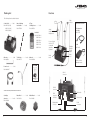
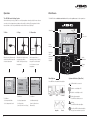
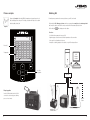
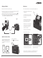
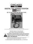
www.jbctools.com
English
Nano Soldering station
Ref. NANE-A
w w w.jbctools.com
Packing List
Features
The following items should be included:
Control Unit ............... 1 unit
Ref. NAE-1A (120V)
NAE-2A (230V)
NAE-9A (100V)
Nano Soldering
Iron Handle ............. 2 units
Ref. NT105-A
8 Type
Cartridge Case ............. 1 unit
Ref. 0011568
Included:
Ref. C105-101 x1
C105-103 x1
C105-105 x2
C105-107 x1
C105-112 x1
C105-113 x2
Allen key ......................... 1 unit
Ref. 009848
Tool Holder ................... 2 units
Ref. 0012755
Manual ............................. 1 unit
Ref. 0014699
Cable
collector
Accessories not included:
Tool extension
cord (1m)
Ref. A1205
Stand:
Intelligent Heat
Management
Process Control:
2.8 Color TFT
screen with
capacitive
keyboard
Cartridge
extractor
and tip
aligner
Pedal
Ref. P-005
Brass
wool
Metal
brush
Puts the tool into
hibernation mode
w w w.jbctools.com
Power Cord .................... 1 unit
Ref. 00094017
USB-A
connector
Nano Soldering station
Ref. NANE-A
USB-B
connector
Accessories already included with the Control Unit:
Cartridge
extractor ....................... 2 units
Ref. 0011806
2
Brass Wool .................... 1 unit
Ref. CL6210
Metal Brush .............. 1 unit
Ref. CL2466
RJ12
connector
for Robot
Main switch
Equipotential
connector
Pedal
connectors
Power socket
3
w w w.jbctools.com
Tool Holder Assembly
Cable assembly
Changing cartridges
Save time and change cartridges safely without having to switch the station off.
Removing
1
2
Inserting
Aligning
Push the cartridge into the
handle to the mark*.
Use the holes to rotate
the cartridges for a proper
alignment.
1
2
For Nano Tweezers
For Nano
Soldering Iron
Place the cartridge in the
slot as shown and pull the
handle to remove it.
*Important
It is essential to insert the cartridges as far as the mark
for a proper connection.
Mark
Compatible cartridges
The NANE-A station works with C105 cartridge range.
See the full range in www.jbctools.com and find the model that best suits your soldering needs.
Changing the tip cleaning system
Replace the tip cleaning system:
- Brass wool
- Inox wool
- Metal brush
¥
Round
¥
Round bent
¥
0,2 x 0,1
Bevel
Chisel
0,7
3,5
Special models
All the cartridges shown are actual size. All measurements are in millimiters (mm).
Contact JBC if you need alternative shapes.
4
5
w w w.jbctools.com
Operation
Work Screen
The JBC Exclusive Heating System
The NANE-A offers an intuitive user interface which provides quick access to station parameters.
Our revolutionary technology is able to recover tip temperature extremely quickly. It means the user
can work at a lower temperature and improve the quality of soldering. Tip temperature is further
reduced thanks to the Sleep and Hibernation modes which increase tip life by 5.
Status Bar
1. Work
2. Sleep
17:14
3. Hibernation
Tool
connected
NT105
350
Power
indicator
Long time in
the stand
When the tool is lifted from the
stand the tip will heat up to the
selected temperature.
When the tool is in the stand,
the temperature falls to
180ºC / 360ºF (preset sleep
temperature).
17:14
17:14
NT105
350
17:14
ºC
Sleep
Hibernation
Tool in the stand
Actual Temp. 25ºC
Temp. Levels
Power
45%
Displayed
when
temperature
levels are
activated
Port
2
Delay to hibernation: 29:30
Tools Menu:
Tools Menu:
· Set Sleep temperature
· Set Sleep delay
(from 0 to 9 min or no Sleep)
· Set Hibernation delay
(from 0 to 60 min or no
hibernation)
380
Port
2
INFO
OK
Station
Information
Change
port
System notifications (Status Bar)
Press INFO for each parameter description.
USB flash drive is connected.
Station is controlled by a PC.
Port
2
Port
2
350
MENU
Actual Temp. 180ºC
Tools Menu:
· Set temperature limits
· Select temperature levels
Station is controlled by a robot.
Station
Tools
Counters
Station software update.
Press INFO to start the process.
Warning.
Press INFO for failure description.
Graphics
6
250
Menu Options
NT105
NT105
Selected 350ºC
Power
45%
After longer periods of
inactivity (pre-set to 30 min.),
the power is cut off and the
tool cools down to room
temperature.
ºC
Reset
Error. Press INFO for failure description,
the type of error and how to proceed.
7
w w w.jbctools.com
Soldering Net
Process analysis
By pressing Graphics in the main MENU, temperature and power figures in real
time are displayed for each port. This helps you decide which tip to use to obtain
the best quality solder joint.
Graphics
1. Download the JBC Manager software and the user manual from www.jbctools.com/manager.html
2. Connect the stations via USB-B connector and the PC will automatically detect them.
3. The notification
will be displayed on the station.
Functions:
- Set all the station parameters from your PC.
- Organize groups of stations and set all their parameters at the same time.
- Store specific configurations for later use.
- Analyze the soldering graphics of the stations on your PC and export them.
17:14
450
400
Power (%)
Remotely manage and monitor as many stations as your PC can handle.
350
300
250
200
Temperature
150
JBC
Manager
software
100
50
Power
Temp
Port 1 - NT105
MENU
OK
See other
port graphic
USB Hub
Export graphics
Insert a USB flash drive into the USB-A
connector to start saving your soldering
process in csv format.
8
any JBC
station
9
w w w.jbctools.com
Working with Robots
Maintenance
Manage and monitor the station using a Robotic system.
Before carrying out maintenance or storage, always allow the equipment to cool.
1. Connect the tool to the port and connect your Robot system to the Robot connector (RJ12).
DB9-RJ12 Adapater available only if necessary (Ref: 0013772).
3. Enable the Robot option in the station settings and the notification will be displayed:
4. Set your Robot’s commands according to the Robot Communication Protocol, available on the
website www.jbctools.com/jbcsoftware-menu-115.html.
- Clean the station screen with a glass cleaner
or a damp cloth.
Robot
Control
Unit
Clean
periodically
- Use a damp cloth to clean the casing and
the tool. Alcohol can only be used to clean
the metal parts.
- Periodically check that the metal parts of
the tool and stand are clean so that the
station can detect the tool status.
- Maintain tip surface clean and tinned prior
to storage in order to avoid tip oxidation.
Rusty and dirty surfaces reduce heat
transfer to the solder joint.
- Periodically check all cables and tubes.
- Replace a blown fuse as follows:
RS-232
connection
Fuse
holder
Update the station software
1. Download the JBC Updater software from
www.jbctools.com/software.html and save
it on a USB flash drive. Preferably one with
no other files.
JBC
Updater
2. Insert the USB flash drive.
The icon
is diplayed while updating.
Fuse holder
Fuse
1. Pull off the fuse holder and remove the
fuse. If necessary use a tool to lever it off.
2. Press the new fuse into the fuse holder
and replace it in the station.
- Replace any defective or damaged pieces. Use original JBC spare parts only.
- Repairs should only be performed by a JBC authorized technical service.
10
11
w w w.jbctools.com
Safety
Exploded View
It is imperative to follow safety guidelines to prevent electric
shock, injury, fire or explosion.
- Do not use the units for any purpose other than soldering or rework. Incorrect use may cause fire.
- The power cord must be plugged into approved bases. Be sure that it is properly grounded
before use. When unplugging it, hold the plug, not the wire.
- Do not work on electrically live parts.
- The tool should be placed in the stand when not in use in order to activate the sleep mode.
The soldering tip, the metal part of the tool and the stand may still be hot even when the station is turned off. Handle with care, including when adjusting the stand position.
- Do not leave the appliance unattended when it is on.
- Do not cover the ventilation grills. Heat can cause inflamable products to ignite.
- Use a “non residue” classified flux and avoid contact with skin or eyes to prevent irritation.
- Be careful with the fumes produced when soldering.
- Keep your workplace clean and tidy. Wear appropriate protective glasses and gloves when working to avoid personal harm.
- Utmost care must be taken with liquid tin waste which can cause burns.
- This appliance can be used by children over the age of eight and also persons with reduced
physical, sensory or mental capabilities or lack of experience provided that they have been given adequate supervision or instruction concerning use of the appliance and understand the hazards involved. Children must not play with the appliance.
- Maintenance must not be carried out by children unless supervised.
12
13
w w w.jbctools.com
Specifications
NANE-1A 120V 50/60Hz. Input fuse: 0.5A. Output: 8.5V
NANE-2A 230V 50/60Hz. Input fuse: 0.2A. Output: 8.5V
NANE-9A 100V 50/60Hz. Input fuse: 0.5A. Output: 8.5V
- Weight: 1.8 Kg (4.0 lb)
- Dimensions: 170 x 90 x 135mm
- Output Peak Power: 14W per tool
- Temperature Range: 90-450°C (190-840ºF) ±5%
- Idle Temp. Stability (still air): ±3 ºC (±5.5 ºF)
- Tip to ground resistance: <2 ohms
- Ambient Operating Temperature: 10-40 ºC (50-104 ºF)
- USB-A / USB-B / Pedal connectors
- RJ12 connector for Robot
Complies with CE standards
ESD protected housing “skin effect”
14
15
This product should not be thrown in the garbage.
In accordance with the European directive 2002/96/EC, electronic equipment at the end of their life
must be collected and returned to an authorized recycling facility.
www.jbctools.com
0014699-1014
Warranty
JBC’s 2 year warranty covers this equipment
against all manufacturing defects, including the
replacement of defective parts and labour.
Warranty does not cover product wear due to use
or mis-use.
In order for the warranty to be valid, equipment
must be returned, postage paid, to the dealer
where it was purchased.