1
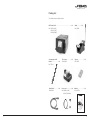
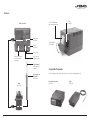
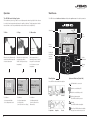
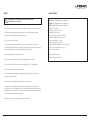
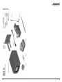
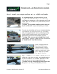
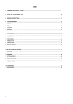
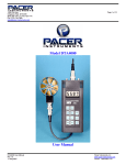
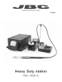
www.jbctools.com
English
Heavy Duty station
Ref. HDE-A
w w w.jbctools.com
Packing List
The following items should be included:
HDE Control Unit ...........................................................................1 unit
Ref. HDE-1A (120V)
HDE-2A (230V)
HDE-9A (100V)
Stand ................ 1 unit
Ref. HD-SD
General purpose HD
Handle ............................. 1 unit
Ref. T470-A
Tip Cleaner.................... 1 unit
Ref. CL9885
Sponge ............................ 1 unit
Ref. S0354
Stand Cable ................. 1 unit
Ref. 0011283
Power cord ......................1 unit
Ref. 0010569 (230V)
0013671 (100/120V)
Manual ............................. 1 unit
Ref. 0013170
w w w.jbctools.com
Heavy Duty station
Ref. HDE-A
2
3
w w w.jbctools.com
Features
2.8” Color TFT screen
with capacitive keyboard
HDE Control Unit
USB-A
connector
Equipotential
connection
USB-B
connector
Tilt the display for
easy reading
Power Socket
Peripheral connector
for joining modules
and pedals
RJ12 connector
for Robot system
C470 cartridges
Required but not
supplied
General purpose
HD Handle
Ref. T470-A
Stand
Ref. HD-SD
4
Compatible Peripherals
Join the station port with 1 module and 1 pedal. See below the compatible peripherals:
Fume Extractor Switch
Ref. FSE-A
Pedal
Ref. P-005
5
w w w.jbctools.com
Adjustable Stand
Tip Cleaner
Improve thermal transfer by cleaning the tip after each solder joint.
Cable collector
Keeps working area free of cable.
Brass wool
Ref. CL6210
Sponge
Ref. S0354
Very effective cleaning
method. It leaves a small layer
of solder on the tip to prevent
oxidation between cleaning
and rewetting.
The least harmful cleaning
method. Keep the sponge damp
with distilled water when working
to avoid tip wear.
Quick tip changer
Splashguard
The cartridge extractor / inserter system
permits switching cartridges without
interrupting your work.
Non-slip base
It minimises splashing
of solder particles
when using the brass
wool.
No need to hold the
base while cleaning
tips.
Wiper
Ref. CL0236
Tapping:
Wiping:
Tap gently to remove
excess solder.
Use the slots to
remove remaining
particles.
A temperature resistant receptacle lets
the operator remove excess solder by
gently tapping or wiping. It can be easily
removed for cleaning.
Optional
Inox wool
Ref. CL6205
Adjustable tool holder
Suits your work position.
6
Brushes
Ref. CL6220
Tip-tinner
Ref. TT-A
Sand
Ref. CL6211
Adjustable cable collector
7
w w w.jbctools.com
Changing cartridges
Compatible Soldering Iron Handles
1. Removing
T470: Handles for Heavy Duty
2. Inserting
Use C470 Cartridge range
Untighten
For intensive soldering jobs requiring continued high thermal power. They feature a non-slip-grip with
a good thermal insulation and a screw which fixes the cartridge and prevents rotation.
General Purpose HD Handle
Ref. T470-A
Untighten the screw. Place the Soldering Iron
in the extractor and remove the cartridge.
General Purpose HD Handle with 3m cable
Ref. T470-SA
Insert the cartridge and press slightly until
the mark*
3. Fixing
Tri-lobed Handle
Ref. T470-ZA
For better handling of the tool.
Mark
Once the cartridge is properly inserted we recommend tightening the screw to prevent moving.
*Important: It is essential to insert the cartridges as far as the mark for a good connection.
Compatible cartridges
The HDE-A works with C470 cartridges and T470 handles. Find the model that best suits your
soldering needs in www.jbctools.com
ø1
ø 1,5
Chisel
Round bent
Thermal Insulator HD Handle with 3m cable
Ref. T470-MA
ø 3,5
Foam
A
Round
Thermal Insulator HD Handle
Ref. T470-FA
Bevel
A
B
Special models
Note: All models are supplied with a 1.5m cable except those specified with 3m.
8
9
w w w.jbctools.com
Operation
Work Screen
The JBC Exclusive Heating System
The HDE-A offers an intuitive user interface which provides quick access to the station parameters.
This revolutionary technology is able to recover tip temperature extremely quickly. It allows the user
to work at a lower temperature and improve the quality of soldering. The tip temperature is further
reduced thanks to the Sleep and Hibernation modes which increase the tip life by 5.
Status Bar
1. Work
2. Sleep
17:14
3. Hibernation
Tool
in use
T470
350
Power
indicator
Long time in
the stand
When the tool is lifted from the
stand the tip will heat up to the
selected temperature.
When the tool is in the stand,
the temperature falls to
180ºC / 360ºF (preset sleep
temperature).
17:14
17:14
T470
350
ºC
Tool in the stand
250
MENU
Port
2
380
Port
2
INFO
OK
Change
port
USB flash drive is connected.
Actual Temp. 25ºC
Station is controlled by a PC.
Port
2
Station is controlled by a robot.
Port
2
Tools Menu:
Tools Menu:
· Set temperature limits
· Select temperature levels
· Set Sleep temperature
· Set Sleep delay
(from 0 to 9 min or no Sleep)
· Set Hibernation delay
(from 0 to 60 min or no
hibernation)
Station
Information
System notifications (Status Bar)
Actual Temp. 180ºC
Delay to hibernation: 29:30
350
Hibernation
Tools Menu:
Station
Tools
Counters
Station software update.
Press INFO to start the process.
Warning.
Press INFO for failure description.
Peripherals
10
Power
45%
Displayed if
temperature
levels are
activated
Press INFO for each parameter description.
T470
Sleep
Temp. Levels
Menu Options
17:14
T470
Selected 350ºC
Power
45%
After longer periods of
inactivity (pre-set to 30 min.),
the power is cut off and the
tool cools down to room
temperature.
ºC
Graphics
Reset
Error. Press INFO for failure description,
the type of error and how to proceed.
11
w w w.jbctools.com
Soldering Net
Process analysis
By pressing Graphics in the main MENU, temperature and power responses in
real time are displayed for each port. This helps you decide which the proper tip is
for every soldering job and the quality of the solder joint.
Graphics
1. Download the JBC Manager software and the user manual from www.jbctools.com/manager.html
2. Connect the stations via USB-B connector and the PC will automatically detect them.
3. The notification
will be displayed on the station.
Functions:
- Set all the station parameters from your PC.
- Organize groups of stations and set all their parameters at the same time.
- Store specific configurations for later uses.
- Analyze the soldering graphics of the stations on your PC and export them.
17:14
450
400
Power (%)
Remotely manage and monitor as many stations as your Windows PC can handle.
350
300
250
200
Temperature
150
100
JBC
Manager
software
50
Power
Temp
Port 1 - T245
MENU
OK
See other
port graphic
USB Hub
Export graphics
Insert a USB flash drive into the USB-A
connector to start saving your soldering
process in csv format.
12
any JBC
station
13
w w w.jbctools.com
Working with Robots
Maintenance
Manage and monitor the station using a Robotic system.
Before carrying out maintenance or storage, always allow the equipment to cool.
1. Connect the tool to the station port by means of the Converter.
2. Connect your Robot system to the Robot connector (RJ12) of the station.
DB9-RJ12 Adapater available only if necessary (Ref: 0013772).
3. Enable the Robot option in the station settings and the notification will be displayed:
4. Set your Robot’s commands according to the Robot Communication Protocol, available on the
website www.jbctools.com/jbcsoftware-menu-115.html.
- Clean the station screen with a glass cleaner
or a damp cloth.
- Periodically check that the metal parts of
the tool and stand are clean so that the
station can detect the tool status.
Converter
Ref. 0002747
Robot
- Use a damp cloth to clean the casing and
the tool. Alcohol can only be used to clean
the metal parts.
Clean periodically
- Maintain tip surface clean and tinned prior
to storage in order to avoid tip oxidation.
Rusty and dirty surfaces reduce heat
transfer to the solder joint.
HDE
Control Unit
RS-232
connection
- Periodically check all cables and tubes.
- Replace a blown fuse as follows:
Fuse
Update the station software
1. Download the JBC Update file from
www.jbctools.com/software.html and save
it on a USB flash drive. Preferably one with
no other files.
JBC
Update file
2. Insert the USB flash drive.
The icon
is diplayed while updating.
Fuse holder
Fuse holder
1. Pull off the fuse holder and remove the
fuse. If necessary use a tool to lever it off.
2. Press the new fuse into the fuse holder
and replace it in the station.
- Replace any defective or damaged pieces. Use original JBC spare parts only.
- Repairs should only be performed by a JBC authorized technical service.
14
15
w w w.jbctools.com
Safety
Specifications
It is imperative to follow safety guidelines to prevent electric
shock, injury, fire or explosion.
- Do not use the units for any purpose other than soldering or rework. Incorrect use may cause fire.
- The power cord must be plugged into approved bases. Be sure that it is properly grounded
before use. When unplugging it, hold the plug, not the wire.
- Do not work on electrically live parts.
- The tool should be placed in the stand when not in use in order to activate the sleep mode.
The soldering tip, the metal part of the tool and the stand may still be hot even when the station is turned off. Handle with care, including when adjusting the stand position.
- Do not leave the appliance unattended when it is on.
HDE-1A 120V 50/60Hz. Input fuse: 4A. Output: 47V
HDE-2A 230V 50/60Hz. Input fuse: 2A. Output: 47V
HDE-9A 100V 50/60Hz. Input fuse: 4A. Output: 47V
- Weight: 5.9 Kg (13.1 lb)
- Dimensions: 145 x 120 x 225mm
- Output Peak Power: 250W
- Temperature Range: 90-500 ºC (190-932 ºF)
- Idle Temp. Stability (still air) ±1.5 ºC (±3 ºF)
- Tip to ground resistance: <2 ohms
- Tip to ground voltage: <2mV RMS
- Ambient Operating Temperature: 10-40 ºC (50-104 ºF)
- USB-A / USB-B / Peripherals connectors
- RJ12 connector for Robot
Complies with CE standards
ESD protected housing “skin effect”
- Do not cover the ventilation grills. Heat can cause inflamable products to ignite.
- Use a “non residue” classified flux and avoid contact with skin or eyes to prevent irritation.
- Be careful with the fumes produced when soldering.
- Keep your workplace clean and tidy. Wear appropriate protective glasses and gloves when working to avoid personal harm.
- Utmost care must be taken with liquid tin waste which can cause burns.
- This appliance can be used by children over the age of eight and also persons with reduced
physical, sensory or mental capabilities or lack of experience provided that they have been given adequate supervision or instruction concerning use of the appliance and understand the hazards involved. Children must not play with the appliance.
- Maintenance must not be carried out by children unless supervised.
16
17
w w w.jbctools.com
Exploded View
18
19
This product should not be thrown in the garbage.
In accordance with the European directive 2002/96/EC, electronic equipment at the end of their life
must be collected and returned to an authorized recycling facility.
www.jbctools.com
0013170-0215
Warranty
JBC’s 2 year warranty covers this equipment
against all manufacturing defects, including the
replacement of defective parts and labour.
Warranty does not cover product wear due to use
or mis-use.
In order for the warranty to be valid, equipment
must be returned, postage paid, to the dealer
where it was purchased.