1
1.
Theory of Operation
1.1
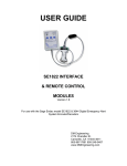
The DME SE1822 Interface Module is a microprocessor controlled
interface that generates the required RS232 command set codes
used by the Endec Model 1822 E.A.S. Encoder/Decoder. The
Interface Module is connected to the DB9 “COM 2” port on the rear
of the Endec and uses the 5 or 8 VDC provided by the Endec for all
power requirements of the Interface Module and the associated
Remote Control. Upon contact closure across the “RWT”,
(Required Weekly Test), terminal block on the Interface Module, or
by depressing the Transmit RWT buttons on the Remote Control,
the proper codes are transmitted in the correct order to activate the
transmission of the RWT. A “PEND RLY” terminal block is provided
on the Interface Module for connecting the Endec “Decoder Active”
relay contacts to the Module when the SE1822 Remote Control is
used. This will notify the operator of a pending alert by a flashing
“Alert Pending” LED on the Remote Control. A 6 wire modular jack
(RJ12) is provided to interface the SE1822 Remote Control or user
defined custom interface connections, such as an automation
system or other normally open switch contacts, to the Interface
Module. RFI protection for the system is included as a part of the
Interface Module and cable design for operation in areas where an
RF environment may be encountered.
1.2
The DME 1822 Remote Control is a passive device containing
switches and indicators to remotely activate the RWT and/or to
relay a pending RMT, (Required Monthly Test). LED indicators are
provided for the following functions. The “Alert Pending” LED
flashes yellow while an alert is pending and a green “Sending Data”
LED is activated when the proper buttons are pushed to initiate
either the RWT or to relay the RMT. An RJ12 modular connector is
provided for interface to the SE1822 Interface Module using the
supplied 50 ft. connecting cable.
1.3
Familiarization with the sections 5.4 and 5.7 of the Endec User
Guide and Reference Manual dealing with filters and relay
programming is recommended for assurance that the Endec is
properly programmed to operate with this system
2.
Connections
2.1
The Interface Module is attached to the “COM 2” DB9 connector on
the rear of the Endec. Secure the Module to the Endec using the
captive screws provided as a part of the Module. If the supplied
Remote Control is to be used with no other user connections
please skip to 2.7.
2