1
2.3.2
INSTALLATION OF THE PC/LAPTOP INTERFACE SOFTWARE
This section involves installation of a software program on the user’s PC. It assumes the user is familiar with
installation of software. Place the first diskette in the disk drive (or CD in the CD-ROM drive). Using
Windows Explorer, browse to A: (or D: for a CD) and double-click on the fire “SETUP”. Follow the
instructions provided on the screen. Installation is straightforward. The installation program assumes that the
communications port you are using is COM1. It is possible that this port is used by on your computer. If this
is the case, select a communications port that is available. When complete, remove the diskette or CD from
your computer.
2.3.3
INSTALLATION OF PNEUMATIC OUTPUT MODULES
These modules should be attached to your machine in the area of your clutch or brake. Drill four #10 or M4
holes in a pattern 4" x W x 7 ½" H. Use four screws to attach the Pneumatic Unit to your machine.
If you are using an oil and water filter, install it in close proximity to the Pneumatic Unit, following the
instructions that come with the filter assembly.
2.3.4
INSTALLATION OF USER INTERFACES
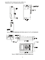
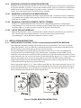
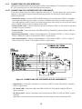
The standard User Interface is designed for mounting in a panel from the front. Refer to Fig. 5 for front mount
panel cutout dimensions and location of mounting holes. An alternate version is designed for rear mounting
with a slightly smaller panel cutout. Refer to Fig. 5 for rear mount panel cutout dimensions and location of
mounting holes You will also need to find a small stud or drill a fifth hole to attach a ground wire.
Mark your panel and cut a square hole to mount the User Interface, taking care not to disturb other equipment
within the machine. You may want to use a rag to prevent metal filings from entering electronic components.
Then drill four 0.150" mounting holes in the correct pattern for attaching the User Interface, plus a fifth hole
for the ground wire.
Assemble your panel to the machine from the front or the rear (depending on the panel you are using) using
#6 or M3 screws, nuts and washers. Attach the ground wire using a fifth set of hardware.
2.4 ELECTRICAL CONNECTIONS FOR STANDARD FEATURES
2.4.1
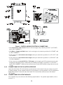
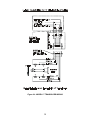
ELECTRICAL CONNECTIONS BETWEEN THE CONTROL MODULE AND THE MACHINE
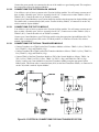
(including power supply connections, see fig.9)
2.4.1.1 NECESSARY CONNECTIONS
The following connections are required for proper operation of the TensionManager™:
1. Make your 24VDC power connection to the terminal block labeled “POWER”, positions 1 (+24 DC) and
2 (24V Common).
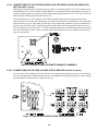
2. Make your single transducer connection to the terminal block labeled “XDUCER”, positions 1 (EXC +), 2
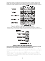
(EXC -), 3 (SIG +) and 4 (SIG -). For the Dual Transducer option use , see Fig. 10)
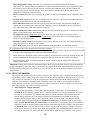
2.4.1.2 CONNECTIONS REQUIRED FOR FEATURES
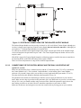
The following connections are required in order to use certain features or modes of operation. Use the
terminal block labeled “CUST CONN”.
• If a 0-10V diameter input signal is used, make the connection to positions 1 (“ROLL DIA 0-10V”) and 9
(“SIG COMMON).
• If a 0-10V line speed input signal is used, make the connection to positions 2 (“LINE SPD 0-10V”) and 9
(“SIG COMMON”)
• If a 0-10V roll speed signal is used, make the connection to positions 3 (“ROLL SPD 0-10V”) and 9 (“SIG
COMMON”).
• If a Remote 0-10V tension signal is used, make the connection to positions 4 (“RTA 0-10V”) and 9 (“SIG
COMMON”).
• If the E-Stop feature is to be used, apply a dry contact to positions 6 (“E-STOP”) and 9 (“SIG COMMON”).
12