1
ASCII_Protocol_Manual Product
User's Manual
Firmware 6.13
Last Update: October 16 2014
Visit www.zaber.com/wiki for more recent updates.
Zaber Technologies Inc.
#2 - 605 West Kent Ave. N.
Vancouver, British Columbia
Canada, V6P 6T7
Table of Contents
Conventions used throughout this document..................................................................................................1
Previous Versions...............................................................................................................................................2
Quick Start.........................................................................................................................................................3
Connecting..............................................................................................................................................3
Talking to Zaber Devices........................................................................................................................3
Making it Move......................................................................................................................................4
Changing a Device Setting......................................................................................................................4
Talking to an Individual Device.............................................................................................................5
Talking to an Individual Axis...........................................................................................................5
Built-in Help...........................................................................................................................................5
Quick Command Reference....................................................................................................................6
Quick Commands.............................................................................................................................6
Quick Device Settings......................................................................................................................7
Message Format...............................................................................................................................................10
Commands............................................................................................................................................10
Replies..................................................................................................................................................11
Warning Flags................................................................................................................................13
Info........................................................................................................................................................14
Alerts.....................................................................................................................................................15
Command Reference.......................................................................................................................................17
estop......................................................................................................................................................17
get..........................................................................................................................................................17
help........................................................................................................................................................18
home......................................................................................................................................................19
io info....................................................................................................................................................19
io get.....................................................................................................................................................20
io set......................................................................................................................................................21
move......................................................................................................................................................22
renumber...............................................................................................................................................23
set..........................................................................................................................................................24
stop........................................................................................................................................................25
stream....................................................................................................................................................25
Setup...............................................................................................................................................26
Interpolated Movement (Lines, Arcs, and Circles)........................................................................27
Trajectory Control..........................................................................................................................28
IOs and Waiting..............................................................................................................................28
Communication Flow Control and Buffers....................................................................................29
Information.....................................................................................................................................31
system reset...........................................................................................................................................31
system restore........................................................................................................................................31
tools echo..............................................................................................................................................32
tools findrange......................................................................................................................................32
tools gotolimit.......................................................................................................................................33
tools parking.........................................................................................................................................34
i
Table of Contents
Command Reference
tools setcomm.......................................................................................................................................34
tools storepos........................................................................................................................................35
trigger....................................................................................................................................................36
Condition Configuration.................................................................................................................37
Command Configuration................................................................................................................38
Trigger Usage.................................................................................................................................39
trigger dist.............................................................................................................................................39
trigger time............................................................................................................................................40
warnings................................................................................................................................................40
Device Settings..................................................................................................................................................42
accel......................................................................................................................................................42
cloop.counts..........................................................................................................................................43
cloop.mode............................................................................................................................................43
cloop.stalltimeout..................................................................................................................................43
cloop.steps.............................................................................................................................................44
comm.address........................................................................................................................................44
comm.alert............................................................................................................................................44
comm.checksum....................................................................................................................................44
comm.protocol......................................................................................................................................45
comm.rs232.baud..................................................................................................................................45
comm.rs232.protocol............................................................................................................................45
comm.rs485.baud..................................................................................................................................46
comm.rs485.enable...............................................................................................................................46
comm.rs485.protocol............................................................................................................................47
comm.usb.protocol................................................................................................................................47
deviceid.................................................................................................................................................47
driver.current.hold.................................................................................................................................48
driver.current.run..................................................................................................................................48
driver.dir................................................................................................................................................48
driver.temperature.................................................................................................................................48
encoder.count........................................................................................................................................49
encoder.dir............................................................................................................................................49
encoder.filter.........................................................................................................................................49
encoder.index.count..............................................................................................................................49
encoder.index.mode..............................................................................................................................49
encoder.index.phase..............................................................................................................................50
encoder.mode........................................................................................................................................50
knob.dir.................................................................................................................................................50
knob.distance........................................................................................................................................51
knob.enable...........................................................................................................................................51
knob.maxspeed......................................................................................................................................51
knob.mode.............................................................................................................................................51
knob.speedprofile..................................................................................................................................52
limit.approach.accel..............................................................................................................................52
limit.approach.maxspeed......................................................................................................................52
limit.detect.decelonly............................................................................................................................52
ii
Table of Contents
Device Settings
limit.detect.maxspeed...........................................................................................................................53
limit.swapinputs....................................................................................................................................53
limit.sensor.action.................................................................................................................................53
limit.sensor.edge...................................................................................................................................53
limit.sensor.pos.....................................................................................................................................54
limit.sensor.posupdate..........................................................................................................................54
limit.sensor.preset.................................................................................................................................55
limit.sensor.state...................................................................................................................................55
limit.sensor.triggered............................................................................................................................55
limit.sensor.type....................................................................................................................................55
limit.max...............................................................................................................................................56
limit.min................................................................................................................................................56
maxspeed...............................................................................................................................................56
motion.accelonly...................................................................................................................................56
motion.decelonly...................................................................................................................................57
peripheralid...........................................................................................................................................57
pos.........................................................................................................................................................57
resolution..............................................................................................................................................57
stream.numbufs.....................................................................................................................................58
stream.numstreams................................................................................................................................58
system.access........................................................................................................................................58
system.axiscount...................................................................................................................................58
system.current.......................................................................................................................................59
system.led.enable..................................................................................................................................59
system.temperature...............................................................................................................................59
system.voltage.......................................................................................................................................59
version...................................................................................................................................................60
Checksumming.................................................................................................................................................61
Verification...........................................................................................................................................61
Example Code.......................................................................................................................................61
C.....................................................................................................................................................61
Python.............................................................................................................................................62
Appendix A - Communication Software........................................................................................................64
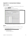
Zaber Console.......................................................................................................................................64
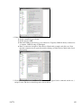
PuTTY..................................................................................................................................................64
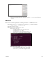
Minicom................................................................................................................................................66
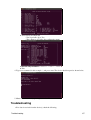
Troubleshooting....................................................................................................................................67
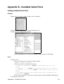
Appendix B - Available Serial Ports...............................................................................................................69
Finding Installed Serial Ports................................................................................................................69
Windows.........................................................................................................................................69
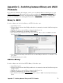
Appendix C - Switching between Binary and ASCII Protocols..................................................................71
Binary to ASCII....................................................................................................................................71
ASCII to Binary....................................................................................................................................71
iii
Table of Contents
Appendix C - Switching between Binary and ASCII Protocols
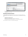
Resetting to Default Protocol................................................................................................................72
iv
Conventions used throughout this document
• Fixed width type indicates ASCII characters communicated to and from a device.
• The ↵ symbol indicates a carriage return, which can be achieved by pressing enter when using a
terminal program.
Conventions used throughout this document
1
Previous Versions
As new features are added to the ASCII protocol, archived versions of this manual will become available
below. Please consult the correct manual for your device version.
Low Version
6.06
6.09
6.11
6.12
High Version
6.08
6.10
6.11
6.12
Previous Versions
Manual
ASCII Protocol Manual 6.06 - 6.08.pdf
ASCII Protocol Manual 6.09 - 6.10.pdf
ASCII Protocol Manual 6.11 - 6.11.pdf
ASCII Protocol Manual 6.12 - 6.12.pdf
2
Quick Start
Connecting
Zaber A-Series devices support connecting to user equipment over standard serial connections using a
human-readable, text-based protocol. This allows A-Series devices to interface with a variety of equipment
and software, including:
• Zaber Console
• Terminal Emulators
• User programs
• PLCs
• Automation and Instrumentation packages
Zaber's range of A-Series devices can be up and running in a matter of minutes, no matter what environment
is being used.
A-Series devices typically communicate over RS232 at 9600 or 115200 baud, with 8 bits, 1 stop bit and no
parity, however please refer to the RS232 Communications section of the device-specific User Manual for the
correct settings. Characters are not echoed by the device, so if a terminal emulator is being used, it is
advisable to turn on local echo.
For detailed instructions on how to set up and configure various communication software, please refer to the
Communication Software section below.
Talking to Zaber Devices
Zaber devices listen for Commands sent to them over a serial port and then immediately respond with a
Reply. Commands always begin with a / and end with a new line. Some commands take parameters, which
are separated by spaces. Two example commands are:
/1 help↵
/1 move abs 10000↵
Where the move command has parameters of abs and 10000.
Replies begin with a @, have 4 or more parameters and end with a new line. For example, the most common
reply is:
@01 0 OK IDLE -- 0
Which can be broken down into:
@
01
0
OK
IDLE
-0
Quick Start
A Reply
The id of the device sending the reply
The reply scope. 0 for the device or all axes, 1 onwards for an individual a
The command succeeded.
The device isn't moving, otherwise BUSY if it is moving.
No faults or warnings in the device
The return value, typically 0.
3
A complete description of the reply fields is available in the Replies section.
Devices can also send two other types of messages; Alerts, starting with ! and Info, starting with #. Info
messages are commonly seen in response to a help command.
Making it Move
Before a device can moved, it first needs to establish a reference to the home position. This is achieved by
sending the home command, as shown below:
/home↵
@01 0 OK BUSY WR 0
If the device isn't homed and a move command is attempted, the device will respond with a rejection reply
and the Invalid Reference (WR) flag set:
/move rel 10000↵
@01 0 RJ IDLE WR BADDATA
Once the device has been homed, you can make the device move by sending a move command. For example,
to move 10000 microsteps forward from the current position:
/move rel 10000↵
@01 0 OK BUSY -- 0
To move 10000 microsteps away from the home position, regardless of the current position:
/move abs 10000↵
@01 0 OK BUSY -- 0
Changing a Device Setting
All of the device settings are read and modified using the get and set commands. For example, to query the
device maxspeed:
/get maxspeed
@01 0 OK IDLE -- 153600
The maximum speed setting is currently 153600. The speed in microsteps/sec is calculated as data/1.6384,
which equates to 93570 microsteps/sec for the data value of 153600.
On a multi axis device, the same command would return a value for each of the axes. For example:
/get maxspeed
@01 0 OK IDLE -- 153600 153600
To set the device to move at a target speed of 50000 microsteps/sec, the speed setting would be modified as
shown below:
/set maxspeed 81920
@01 0 OK IDLE -- 0
Talking to Zaber Devices
4
On a multi axis device, the command above would set the speed for all axes. To only query or set a value for a
specific axis, see the Talking to an Individual Axis section below.
Talking to an Individual Device
Up until now all the commands that have been sent haven't included a device address. If you have more than
one device in a chain, you may have noticed that all of the devices moved at once in the Making it Move
example above and that multiple responses were received. While this is a handy feature for initial setup,
general use requires a way to instruct only an individual device to move.
Devices can be addressed by including their device number before the command. For example, the following
command instructs only device 1 to move:
/1 move abs 10000↵
@01 0 OK BUSY -- 0
The valid device addresses are from 1 - 99 inclusive and can include a leading zero for devices 1 - 9. For
example either 01 or 1 would both refer to device 1.
Talking to an Individual Axis
On multi axis devices, all the commands shown above would have affected all axes in the device. In order to
get only a single axis to move an axis number has to be provided after the device number. The following
command would instruct the first axis on a device to move to position 10000.
/1 1 move abs 10000↵
@01 1 OK BUSY -- 0
Note that this time the response scope is 1, indicating that the following information applies to axis 1.
Valid axis numbers are 0 - 9 inclusive, where 0 means all axis of the device, depending on the command or
setting.
Built-in Help
All Zaber A-Series devices feature built-in help, providing a quick and easy reference for all Commands and
Settings that the device has. Help commands require a device number to be provided. For example to access
the built-in help for device 1, send: /1 help↵.
The device will respond with a detailed description on how to access specific information about commands
and replies, as shown below:
/1 help↵
@01 0 OK IDLE WR 0
#01 0 COMMAND USAGE:
#01 0 '/stop'
stop all devices
#01 0 '/1 stop'
stop device number 1
#01 0 '/1 2 stop'
stop device number 1 axis number 2
#01 0
#01 0 Type '/help commands' for a list of all top-level commands.
#01 0 Type '/help reply' for a quick reference on reply messages.
#01 0 Visit www.zaber.com/support for complete instruction manuals.
Changing a Device Setting
5
Note that you can view a list of all the top level commands available to device 1 by using /1 help
commands↵. To access help for a specific command, for example the move command, send:
/1 help move↵
@01 0 OK IDLE -- 0
#01 0 move abs {x}
#01 0 move rel {x}
#01 0 move vel {x}
#01 0 move min
#01 0 move max
Move
Move
Move
Move
Move
to
by
at
to
to
absolute position
relative position
constant velocity
minimum position
maximum position
Quick Command Reference
The following table offers a quick command and setting reference for ASCII devices. For more detailed
information, refer to the Command Reference or Device Settings below.
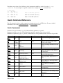
Quick Commands
Parameters in square brackets, e.g. [clr], indicate that the parameter is optional.
Parameters in italics, e.g. value, indicate that data, typically a number, needs to be provided.
Parameters separated by a pipe, e.g. abs|rel, indicate that one of the parameters in the set need to be provided.
Command
estop
Scope
Parameter(s)
Axis
Returns
0
home
Device
setting
and Axis
commands
Device
reply
command ...
Axis
io info
Device
[ai|ao|do|di]
ports
io get
Device
ai|ao|do|di [channel]
value
io set
Device
ao channel value
do channel value
do port value value2...
0
move
Axis
abs|rel|vel value
0
move
Axis
min|max
0
move
Axis
stored number
0
renumber
Device
value
Device
setting value
and Axis
0
Axis
0
get
help
set
stop
Built-in Help
value
0
0
0
Description
Performs an emergency stop on the
axis.
Retrieves the current value of the
device or axis setting.
Displays the help information for the
system.
Moves the axis to the home position.
Returns the number of I/O channels
the device has.
Returns the current value of the
specified I/O channel type.
Sets the specified output channel to
value.
Moves the axis to various positions
along its travel.
Moves the axis to the limits of
travel.
Moves the axis to a previously
stored position.
Renumbers all devices in the chain.
Sets the device or axis setting setting
to the value.
Decelerates the axis and brings it to
a halt.
6
stream
Device
Refer to the
documentation below
Refer to the
documentation
below
system reset Device
0
system
restore
Device
0
tools echo
Device
tools
findrange
tools
gotolimit
(message)
Axis
0
0
Axis
limit dir action update
0
tools
parking
Device
state|park|unpark
0|1
tools
setcomm
Device
rs232baud protocol
0
tools
storepos
Axis
number [position|current] 0|position
trigger
Device
Refer to the
documentation below
trigger dist Device
trigger time Device
warnings
Axis
0
number axis displacement
number enable [count]
0
number disable
number period
number enable [count]
0
number disable
[clear]
0
Performs an action related to
streamed, interpolated multi-axis
motion.
Resets the device, as it would appear
after power up.
Restores common device settings to
their default values.
Echoes the provided message (if
any) back to the user.
Uses the home and away sensors to
set the valid range of the axis.
Moves the axis to a limit sensor and
performs the provided actions.
Parking allows the device to be
turned off and used at a later time
without first having to home.
Sets RS232 baud rate and
communication protocol for RS232
and USB.
Stores a number of positions for easy
movement.
Configures actions to be performed
on the device when a certain
condition is met.
Configures a trigger to toggle a
digital output line every
displacement microsteps.
Configures a periodic trigger to
toggle a digital output line every
period milliseconds.
Displays the active device and axis
warnings, optionally clearing them if
applicable.
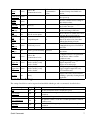
Quick Device Settings
The settings listed below can be inspected and modified with the get and set commands described above.
Setting
accel
cloop.counts
cloop.mode
cloop.stalltimeout
cloop.steps
comm.address
Quick Commands
Scope Writable
Description
Axis Yes
Sets the acceleration used to modify the speed.
The number of counts generated by the encoder for one full
Axis Yes
revolution.
Axis Yes
Sets the closed loop control mode.
The amount of time to wait after a stall/displacement condition,
Axis Yes
in milliseconds.
The number of full steps required for the motor to complete one
Axis Yes
revolution.
Device Yes
The device address.
7
comm.alert
Device Yes
comm.checksum
Device Yes
comm.protocol
Device Yes
comm.rs232.baud
comm.rs232.protocol
comm.rs485.baud
comm.rs485.enable
comm.rs485.protocol
comm.usb.protocol
deviceid
Device
Device
Device
Device
Device
Device
Device
Yes
Yes
Yes
Yes
Yes
Yes
No
driver.current.hold
Axis
Yes
driver.current.run
driver.dir
driver.temperature
encoder.count
encoder.dir
encoder.filter
encoder.index.count
encoder.index.mode
encoder.index.phase
encoder.mode
knob.dir
Axis
Axis
Axis
Axis
Axis
Axis
Axis
Axis
Axis
Axis
Axis
Yes
Yes
No
Yes
Yes
Yes
Yes
Yes
Yes
Yes
Yes
knob.distance
Axis
Yes
knob.enable
Axis
Yes
knob.maxspeed
Axis
Yes
knob.mode
Axis
Yes
knob.speedprofile
Axis
limit.approach.accel
Axis
limit.approach.maxspeed Axis
Yes
Yes
Yes
limit.detect.decelonly
Axis
Yes
limit.detect.maxspeed
Axis
Yes
limit.swapinputs
Axis
Yes
limit.home.action
limit.home.edge
limit.home.posupdate
limit.home.preset
limit.home.state
Axis
Axis
Axis
Axis
Axis
Yes
Yes
Yes
Yes
No
Quick Device Settings
The device will send alert messages when this setting is 1.
The device includes checksums in its messages if this setting is
set to 1.
The communications protocol used by the device on the current
interface.
The baud rate used by RS232 Prev and Next interfaces.
The protocol used by RS232 Prev and Next interfaces.
The baud rate used by RS485 interface.
Enables the RS485 interface.
The protocol used by RS485 interface.
The protocol used by the usb interface.
The device id for the unit.
Current used to hold the motor in position, as a percentage of
maximum.
Current used to drive the motor as percentage of maximum.
Reverse the motor driver output direction.
The current temperature of the axis driver, in degrees Celsius.
The recorded counts of the axis encoder.
Inverts the counting direction for the axis encoder.
Enable and set up digital filtering of the encoder inputs.
The recorded counts of the axis encoder index pulse.
The operating mode of the axis encoder index signal.
The required phase for an index pulse to be counted.
The operating mode of the axis encoder.
Sets the movement direction for the knob.
Sets how far the device moves with each step of the knob in
displacement mode, in units of microsteps.
Disable the use of the knob when set to 0.
The maximum speed that can be reached using the knob in
velocity mode.
Sets the mode of the knob. 0 for velocity mode, 1 for
displacement mode.
Sets the profile to be used per increment when in velocity mode.
Acceleration used when approaching a limit sensor.
Maximum speed used when approaching a limit sensor.
Deceleration used when stopping after a limit sensor has
triggered.
Maximum speed used when moving away from a limit sensor.
Reverses the limit positions by swapping the home and away
sensors.
Automatic limit switch action.
Sensor edge to align action to.
Position update to occur when sensor is triggered.
The default position of the home sensor.
The state of the home sensor.
8
limit.home.triggered
limit.home.type
limit.away.action
limit.away.edge
limit.away.posupdate
limit.away.preset
limit.away.state
limit.away.triggered
limit.away.type
limit.c.action
limit.c.edge
limit.c.pos
limit.c.posupdate
limit.c.preset
limit.c.state
limit.c.triggered
limit.c.type
limit.d.action
limit.d.edge
limit.d.pos
limit.d.posupdate
limit.d.preset
limit.d.state
limit.d.triggered
limit.d.type
Axis
Axis
Axis
Axis
Axis
Axis
Axis
Axis
Axis
Axis
Axis
Axis
Axis
Axis
Axis
Axis
Axis
Axis
Axis
Axis
Axis
Axis
Axis
Axis
Axis
No
Yes
Yes
Yes
Yes
Yes
No
No
Yes
Yes
Yes
Yes
Yes
Yes
No
No
Yes
Yes
Yes
Yes
Yes
Yes
No
No
Yes
limit.max
Axis
Yes
limit.min
Axis
Yes
maxspeed
motion.accelonly
motion.decelonly
peripheralid
pos
resolution
stream.numbufs
stream.numstreams
system.access
system.axiscount
system.current
system.led.enable
system.temperature
system.voltage
version
Axis
Axis
Axis
Axis
Axis
Axis
Device
Device
Device
Device
Device
Device
Device
Device
Device
Yes
Yes
Yes
Yes
Yes
Yes
No
No
Yes
No
No
Yes
No
No
No
Quick Device Settings
Whether the home sensor has been triggered previously.
The type of home sensor connected.
Automatic limit switch action.
Sensor edge to align action to.
Position update to occur when sensor is triggered.
The default position of the away sensor.
The state of the home sensor.
Whether the away sensor has been triggered previously.
The type of away sensor connected.
Automatic limit switch action.
Sensor edge to align action to.
The updated position of the sensor, when triggered.
Position update to occur when sensor is triggered.
The default position of the c limit sensor.
The state of the c limit sensor.
Whether the c limit sensor has been triggered previously.
The type of c limit sensor connected.
Automatic limit switch action.
Sensor edge to align action to.
The updated position of the sensor, when triggered.
Position update to occur when sensor is triggered.
The default position of the d limit sensor.
The state of the d limit sensor.
Whether the d limit sensor has been triggered previously.
The type of d limit sensor connected.
The maximum position the device can move to, measured in
microsteps.
The minimum position the device can move to, measured in
microsteps.
The maximum speed the device moves at.
Sets the acceleration used to increase the speed.
Sets the deceleration used when decreasing the speed.
The id of the connected peripheral.
The current absolute position of the device.
Microstep resolution
The number of stream buffers provided in the device.
The number of streams provided in the device.
Sets the access level of the user.
The number of axes in the device.
The current being drawn by the device and motors.
Enables the front panel LEDs.
The current temperature of the unit, in degrees Celsius.
The voltage being applied to the device.
The firmware version of the device.
9
Message Format
The protocol uses a command-reply model, such that:
• Communication must be initiated by a user sending a device a command.
• The device always responds with one reply immediately after a command has been received.
• Unless explicitly enabled, a device will not send any message other than a reply to a command.
The contents of the message is space delimited, with consecutive spaces being treated as a single space. There
is only one command or response per message. Sending multiple commands in a single message is not
supported.
Commands
Commands are sent from the user to one or more devices, which always and immediately respond with a
Reply. The data field in the command is case sensitive, space delimited and depends on the command being
executed. See the Command Reference for all the available commands.
A command instructs the device to perform an operation. A typical command message and associated fields
are:
/1 1 move abs 10000↵
/n a xxxx yyy yyyyy[:CC]ff
/ - Message Type
Length: 1 byte.
The message type for a command is always /.
This field, and the footer, are the only required fields, all others are optional.
n - Device Address
Length: 1+ bytes.
The address indicates which device number should perform the command. The address is optional and
if left out, or set to zero, the command is executed by all devices on the chain. Device addresses range
from 1 - 99 inclusive.
Examples of acceptable addresses are:
0, 00, 1, 01, 000001, 76, 99, 0x00, 0x01, 0x5A, 0x5a
Invalid addresses include:
100, -1, 0x65 - The addresses are out of range and while the message may be valid, no
device will respond.
a - Axis Number
Length: 1 bytes.
The axis number indicates which axis within a device should perform the command. The axis number
is optional and if left out, or set to zero, the command is executed by all axes in the device. Axis
numbers range from 0 - 9 inclusive.
xxxx... - Command
Length: Variable.
Message data containing command information. The contents are space delimited.
Message Format
10
The Command Reference below covers the available commands.
yyy... - Command Parameters
Length: Variable.
Message data containing command parameters and data, the contents are space delimited.
Numerical values can be in decimal, or hexadecimal when prefixed with 0x.
Negative decimal values are prefixed with '-'
The Command Reference below covers the contents of the parameters field for the available
commands.
CC - Message Checksum
Length: 3 bytes.
If provided, the device will reject messages that have been corrupted during transmission.
More information and code examples are provided in the Checksumming section below.
ff - Message Footer
Length: 1 - 2 bytes.
A newline, typically achieved by pressing enter or return. For convenience, the device accepts any
ASCII combination of Carriage Return (CR, \r) and/or Line Feed (LF, \n) as a message footer.
Smallest Command
The smallest valid command is just /↵ which generates a response from all devices in the chain, as
demonstrated below:
/↵
@01 0 OK IDLE -- 0
@03 0 OK IDLE -- 0
@02 0 OK IDLE -- 0
This can be used as a quick way to check that communications and all devices are functioning as expected.
Replies
A reply is sent by the device as soon as it has received a command and determined if it should respond. A
typical response message and associated fields are:
@01 0 OK IDLE -- 0↵
@nn a fl bbbb ww x[:CC]ff
@ - Message Type
Length: 1 byte.
This field always contains @ for a reply message.
nn - Device Address
Length: 2 bytes.
This field contains the address of the device sending the reply, always formatted as two digits.
a - Axis Number
Length: 1 byte.
Commands
11
This field contains the reply scope, from 0 to 9. 0 indicates that the following fields apply to the
whole device and all axes on it, otherwise the fields apply to the specific axis indicated.
fl - Reply Flags
Length: 2 bytes.
The reply flag indicates if the message was accepted or rejected and can have the following values:
◊ OK - The command was valid and accepted by the device.
◊ RJ - The command was rejected. The data field of the message will contain one of the
following reasons:
⋅ BADDATA - The data provided in the command is incorrect or out of range.
⋅ BADCOMMAND - The command or setting is incorrect or invalid.
⋅ PARKED - The device cannot move because it is currently parked.
⋅ STATUSBUSY - The device cannot be parked, nor can certain settings be changed,
because it is currently busy.
⋅ DEVICEONLY - An axis number was specified when trying to execute a device only
command.
⋅ AGAIN - The command cannot be processed right now. The user or application
should send the command again. Occurs only during streamed motion.
⋅ FULL - The device has run out of permanent storage and cannot accept the command.
Occurs when storing to a stream buffer.
bbbb - Device Status
Length: 4 bytes.
This field contains BUSY when the axis is moving and IDLE otherwise. All movement commands,
including stop, put the axis into the BUSY state, while they are being executed. During streamed
motion, wait commands are considered to be busy, not idle. If the reply message applies to the whole
device, the status is BUSY if any axis is busy and IDLE if all axes are idle.
ww - Warning Flags
Length: 2 bytes.
Contains the highest priority warning currently active for the device or axis, or -- under normal
conditions. A full description of the flags is available in the Warning Flags Section.
xxx.. - Response Data
Length: 1+ bytes.
The response for the command executed. The contents and format of this field vary depending on the
command, but is typically 0 (zero).
CC - Message Checksum
Length: 3 bytes.
A device will append a checksum to all replies if the comm.checksum setting is configured to 1. More
information and code examples are provided in the Checksumming section below.
ff - Message Footer
Length: 2 bytes.
This field always contains a CR-LF combination (\r\n) for a reply message.
Replies on Multi axis Devices
For replies with an axis number of 0, the status and warning flags apply to the whole device. If any axis on the
device is moving, then the reply status will be busy. Similarly the warning flags show the highest warning
Replies
12
across all axes.
For replies with an axis number of 1 or above, the status and warning flags only apply to the axis indicated.
Warning Flags
A warning flag is provided in each device-to-user reply message, indicating whether any device fault or
warning is active. If more than one condition is active, it shows the one with highest precedence.
The warning flags are defined as follows, with the highest priority first:
FD - Driver Disabled.
The driver has disabled itself due to overheating.
This warning persists until the driver returns to normal operating conditions.
FS - Stalled and Stopped.
Stalling was detected and the axis has stopped itself.
This warning persists until acknowledged and cleared by the user with the warnings command.
FB - Stream Bounds Error
A previous streamed motion could not be executed because it failed a precondition (e.g. motion
exceeds device bounds, calls nested too deeply).
This warning persists until acknowledged and cleared by the user with the warnings command; also,
until the warning is cleared, no further streamed motions can be sent to the failed stream.
FP - Interpolated Path Deviation.
Streamed motion was terminated because an axis slipped and thus the device deviated from the
requested path.
This warning persists until acknowledged and cleared by the user with the warnings command.
FE - Limit Error.
The axis took too long to reach the target limit sensor.
This warning persists until acknowledged and cleared by the user with the warnings command.
WL - Unexpected Limit Trigger.
A limit sensor triggered unexpectedly. This occurs when an automatic limit sensor action is carried
out on a previously triggered sensor.
This warning persists until acknowledged and cleared by the user with the warnings command.
WV - Voltage out of range.
The supply voltage is outside the recommended operating range of the device. Damage could result to
the device if not remedied.
This warning persists until the condition is remedied.
WT - System Temperature High
The internal temperature has exceeded the recommended limit for the device.
This warning persists until the over temperature condition is remedied.
WM - Displaced when stationary.
While not in motion, the axis has been forced out of its position.
This warning persists until the axis is moved.
WR - No Reference Position.
Axis has not had a reference position established.
This warning persists until the axis position is updated via homing or any command/action that sets
position.
NC - Manual Control.
Axis is busy due to manual control via the knob.
This warning persists until a movement command is issued.
Warning Flags
13
NI - Command Interrupted.
A movement operation (command or manual control) was requested while the axis was executing
another movement command. This indicates that a movement command did not complete.
This warning persists until a movement command is issued when the axis is either idle or executing a
manual control movement.
ND - Stream Discontinuity
The device has slowed down while following a streamed motion path because it has run out of queued
motions.
This warning persists until the stream has enough motions queued that it no longer needs to decelerate
for that reason, or until the stream is disabled.
NU - Setting Update Pending.
A setting is pending to be updated.
This warning is cleared automatically, once the settings have been updated.
To see and clear all current warnings, use the warnings command.
Info
This message type contains extra information from the device for testing/debugging/programming purposes.
One or more info messages can follow a reply or alert message. This message type is designed to be read by
the user and to be ignored by software.
A typical info message and its fields are:
#01 0 Visit www.zaber.com/support for complete instruction manuals.↵
#nn a xxxxxxxxxxxxx...[:CC]ff
# - Message Type
Length: 1 byte.
This field always contains # for an info message.
nn - Device Address
Length: 2 bytes.
This field contains the address of the device sending the reply, always formatted as two digits.
a - Axis number.
Length: 1 byte.
Always 0 for info messages.
xxx.. - Data
Length: 1+ bytes.
The data for the info message, typically human readable text.
CC - Message Checksum
Length: 3 bytes.
A device will append a checksum to all info messages if the comm.checksum setting is configured to
1. More information and code examples are provided in the Checksumming section below.
ff - Message Footer
Info
14
Length: 2 bytes.
This field always contains a CR-LF combination (\r\n) for a info message.
The common occurrence of info messages is in reply to a help command, e.g.:
/1 help↵
@01 0 OK IDLE WR 0
#01 0 COMMAND USAGE:
#01 0 '/stop'
stop all devices
#01 0 '/1 stop'
stop device number 1
#01 0 '/1 2 stop'
stop device number 1 axis number 2
#01 0
#01 0 Type '/help commands' for a list of all top-level commands.
#01 0 Type '/help reply' for a quick reference on reply messages.
#01 0 Visit www.zaber.com/support for complete instruction manuals.
Alerts
An alert message is sent from a device when a motion command has completed.
If it is enabled, this message can be sent at any time without being preceded by a command from the user.
This message type is used for informational purposes or time-sensitive operations.
Alerts are controlled by the comm.alert setting, which has to be 1 for the device to send status alerts.
A typical alert message and its fields are:
!01 0 IDLE --↵
!nn a ssss ww[:CC]ff
! - Message Type
Length: 1 byte.
This field always contains ! for an alert message.
nn - Device Address
Length: 2 bytes.
This field contains the address of the device sending the alert, always formatted as two digits.
a - Axis Number
Length: 1 byte.
ssss - Device status.
Length: 4 bytes.
This field contains BUSY when the axis is moving and IDLE when the axis is stopped.
ww - Warning flags.
Length: 2 bytes.
Contains the highest priority warning currently active for the axis, or -- under normal conditions. A
full description of the flags is available in the Warning Flags Section.
CC - Message Checksum
Length: 3 bytes.
Alerts
15
A device will append a checksum to all alert messages if the comm.checksum setting is configured to
1. More information and code examples are provided in the Checksumming section below.
ff - Message Footer
Length: 2 bytes.
This field always contains a CR-LF combination (\r\n) for an alert message.
Multi axis Alerts
On a multi axis device with completion alerts enabled, an alert will be generated each time an axis stops. In
the example below, axis 2 is closer to it's maximum position than axis 1 is:
/move
@01 0
!01 2
!01 1
max↵
OK BUSY -- 0
IDLE -IDLE --
The first alert is generated when axis 2 stops, and as that axis is idle, the axis-scope reply has IDLE in its
ssss field, even though the device as a whole is still busy due to axis 1 moving. The second alert is
generated when axis 1 stops.
Alerts
16
Command Reference
The following section details all commands that are available in the ASCII protocol. For specific device
support of a command, please refer to that device's User Manual.
For commands with a device scope, specifying an axis number other than zero in the command will result in a
DEVICEONLY error, as shown below:
/1 tools parking park↵
@01 0 OK IDLE -- 0
/1 0 tools parking park↵
@01 0 OK IDLE -- 0
/1 1 tools parking park↵
@01 1 RJ IDLE -- DEVICEONLY
For commands with an axis scope, specifying an axis number of zero or not including any axis number will
both apply the command to all axes on the device. If one of the axes is unable to complete the command, a
BADDATA response will be returned and none of the axes will perform the command. For example, moving
to a position that is outside the range of one axis, but within for another axis will result in an error:
/1 get limit.max↵
@01 0 OK IDLE -- 3038763 6062362
/1 move abs 4750000↵
@01 0 RJ IDLE -- BADDATA
Parameters in square brackets, e.g. [clr], indicate that the parameter is optional. Parameters in italics, e.g.
value, indicate that data, typically a number, needs to be provided. Parameters separated by a pipe, e.g. abs|rel,
indicate that one of the parameters in the set needs to be provided.
estop
Performs an emergency stop on the axis.
Scope
Axis
Parameters
none
The device is forced to zero velocity, no control of deceleration is performed.
Example Usage:
/1 1 estop↵
@01 1 OK IDLE -- 0
get
Retrieves the current value of the device or axis setting.
Command Reference
17
Scope
Device and Axis
Parameters
setting The name of one of the Device Settings.
See Device Settings for a detailed list or settings and what they do.
Example Usage:
Viewing the device id:
/get deviceid↵
@01 0 OK IDLE -- 20022
Device id is 20022 (A-LSQ150B)
Viewing an invalid setting:
/get cloop.mode↵
@01 0 RJ IDLE -- BADCOMMAND
cloop.mode is only valid on devices with encoders, and this device does not have one. Attempting to
read an invalid setting results in a BADCOMMAND rejection reply.
help
Displays the built-in help.
Scope
Device
Parameters
[commands|reply|warnflags|enumscommand]
commands list
Displays the help information for the system, commands and replies or a specific command as applicable. This
command will always return a successful reply and the help information will be returned in info messages.
help warnflags displays information about the warning flags that can be present in a reply.
help commands list can be used to list all supported commands and settings of the device.
As the built-in help is specific to each device, a device number is required when sending the command.
Issuing a help command without a device number will result in each device in the chain requesting that a
device number be specified, as shown below:
/help↵
@01 0 OK IDLE -- 0
#01 0 Please provide a device address for querying help
get
18
@02 0 OK IDLE -- 0
#02 0 Please provide a device address for querying help
Example Usage:
View the built-in help for the estop command
/1 help estop↵
@01 0 OK IDLE -- 0
#01 0 estop Emergency stop
Help for an invalid command returns successfully:
/1 help dlkjsfbi↵
@01 0 OK IDLE -- 0
#01 0 No help found
home
Moves the axis to the home position.
Scope
Axis
Parameters
none
The axis is moved towards the home position (closest to the motor generally) at the lesser of the
limit.approach.maxspeed and maxspeed settings. Once the home position is reached, the current position is
reset to the limit.home.preset. Additionally, limit.home.triggered is set to 1, and the No Reference Position
(WR) warning flag is cleared. This command is equivalent to tools gotolimit home neg 2 0.
Example Usage:
/home↵
@01 0 OK BUSY WR 0
NOTE: Upon power up or setting changes, this command should be issued to obtain a reference position.
Otherwise, motion commands may respond with a rejection reply or behave unexpectedly.
io info
Returns the number of I/O channels the device has.
Scope
Device
Parameters
help
19
[ao|ai|do|di]
The parameters are used to specify the channel type: ai for Analog Input, ao for Analog Output, di for Digital
Input and do for Digital Output. Channel numbers start at 1 for each type.
If the channel type is not specified, all channels will be returned in the following order: analog out, analog in,
digital out, digital in
Example Usage:
Getting the available io configuration:
/io info↵
@01 0 OK IDLE -- 0 4 4 4
Device has no analog outputs, 4 analog input channels, 4 digital outputs and 4 digital inputs.
Getting the configuration of a specific port type:
/io info ao↵
@01 0 OK IDLE -- 0
Device has no analog output capabilities
Invalid port type:
/io info as↵
@01 0 RJ IDLE -- BADCOMMAND
io get
Get the current value of the specified I/O channel type.
Scope
Device
Parameters
ao|ai|do|di [channel]
If channel isn't specified a space delimited list of all channels of the requested type are returned.
For digital channels, a value of 0 indicates that the input or output is not conducting and a value of 1 indicates
that the channel is conducting.
For analog channels, the vaule returned is a measurement of the voltage present on the input with enough
decimal places to cover the available resolution. To see the available resolution, please consult the Series
Specs Tab on the device Product Page.
Example Usage:
io info
20
Reading an analog input:
/io get ai 2↵
@01 0 OK IDLE -- 7.5
Analog input 2 has 7.5V on it
Reading all digital outputs:
/io get do↵
@01 0 OK IDLE -- 0 0 1 0
Digital output 3 is high while the rest are low.
Invalid port type:
/io get as 0↵
@01 0 RJ IDLE -- BADCOMMAND
Invalid channel number, using the available channels from the io info command above:
/io get ai 5↵
@01 0 RJ IDLE -- BADDATA
/io get ao↵
@01 0 RJ IDLE -- BADDATA
The analog output port has no channels and can't be displayed.
io set
Sets the specified output.
Scope
Device
Parameters
do channel value
do port value value2...
Sets the specified output channel to value.
For digital channels, a value of 0 clears the output while any other value sets it.
Specifying 'port' allows setting of all digital outputs at once.
Example Usage:
Clear digital output 3:
/io set do 3 0↵
@01 0 OK IDLE -- 0
io get
21
Using the port command to set digital output 1, 3, 4 and clear output 2:
/io set do port 1 0 1 1↵
@01 0 OK IDLE -- 0
Invalid port type:
/io set ad 2 50↵
@01 0 RJ IDLE -- BADCOMMAND
Port type that's not an output or has no channels:
/io
@01
/io
@01
set ai 2 50↵
0 RJ IDLE -- BADDATA
set ao 2 50↵
0 RJ IDLE -- BADDATA
Invalid channel number:
/io set do 8 1↵
@01 0 RJ IDLE -- BADDATA
move
Moves the device to various positions along its travel.
Scope
Axis
Parameters
abs|rel|vel value
min|max
stored number
value is in units of microsteps.
abs moves to the absolute position of value. Value must be in the range [ limit.min,limit.max ].
rel moves the axis by value microsteps, relative to the current position. Value must be in the range [ limit.min
- pos, limit.max - pos ].
vel moves the axis at the velocity specified by value until a limit is reached. Value must be in the range [
-resolution*16384, resolution*16384 ].
min moves the axis to the minimum position, as specified by limit.min.
max moves the axis to the maximum position, as specified by limit.max.
stored moves the axis to a previously stored position. number specifies the stored position number, from 1 16. Refer to the tools storepos command for more information.
io set
22
Example Usage:
Move all axes on the device forward by 200000 microsteps:
/move rel 200000↵
@01 0 OK BUSY -- 0
No reference point:
/move rel 2000000↵
@01 0 RJ IDLE WR BADDATA
The WR flag indicates that there is no reference point and the axis has not been homed. Sending the
home command will allow the move command to succeed.
Invalid position:
/get limit.max↵
@01 0 OK IDLE -- 305381
/move abs 305888↵
@01 0 RJ IDLE -- BADDATA
A bad data rejection was received because the position specified is beyond the range of the axis.
Parked:
/move abs 10000↵
@01 0 RJ IDLE -- PARKED
Axes cannot be moved when the device is parked. Either unpark or home it.
renumber
Renumbers a device, or all devices in a chain.
Scope
Device
Parameters
[value] Valid range: 1 - 99.
The global version of this command sequentially renumbers all devices in the chain, starting with value, if
provided, or 1. The global renumber command only works on interfaces that support daisy chaining; issuing a
global renumber command over an interface that doesn't support daisy chaining will be rejected with a
BADCOMMAND. Please consult the device User Manual to determine which interfaces support daisy
chaining.
When a specific device address is sent the renumber command, the renumber command will change the
device number to value (in which case value is required).
When a device receives a renumber command, it will use the new device number for it's response.
Example Usage:
move
23
Renumbering all devices in the chain:
/renumber↵
@01 0 OK IDLE -- 0
@02 0 OK IDLE -- 0
The devices renumbered, with the device closest to the computer being at address 1, and the next
closest being at address 2.
Renumbering a specific device:
/2 renumber 4↵
@04 0 OK IDLE -- 0
Device 2 renumbered and replied on address 4.
This is equivalent to /2 set comm.address 4↵
Invalid device number:
/renumber 999↵
@01 0 RJ IDLE -- BADDATA
The requested device number was outside of the allowable range.
NOTE: The device will reply on its new address, not the address the command was sent to.
set
Sets the device setting.
Scope
Device and Axis
Parameters
setting value
Sets the device setting setting to the value. See Device Settings for a detailed list or settings and what they do.
Example Usage:
Writing a device setting:
/set knob.enable 1↵
@01 0 OK IDLE -- 0
The device setting was successfully configured.
Invalid value:
/set knob.enable 7↵
@01 0 RJ IDLE -- BADDATA
Invalid setting:
renumber
24
/get system.voltage↵
@01 0 OK IDLE -- 0
/set system.voltage 0↵
@01 0 RJ IDLE -- BADCOMMAND
It's possible to read from some settings but not write to them.
stop
Decelerates an axis and brings it to a halt.
Scope
Axis
Parameters
none
To quickly stop an axis, see the estop command.
Example Usage:
/stop↵
@01 0 OK BUSY -- 0
stream
Performs an action related to streamed, interpolated multi-axis motion.
Scope
Device
Parameters
number
number
number
buffer
buffer
number
number
number
number
number
number
number
number
number
number
number
number
number
set
setup live axes
setup store buf axiscount
setup disable
buf erase
buf print
arc abs|rel cw|ccw centrex centrey endx endy
call buf
circle abs|rel cw|ccw centrex centrey
fifo cork|uncork
info
io set do channel value
io set do port value value2…
line abs|rel endx endy…
set maxspeed value
set tanaccel value
set centripaccel value
wait milliseconds
wait io ai|di channel ==|<>|<|>|<=|>= value
25
While most commands will pre-empt previous commands, a stream allows the execution of a series of
subsequent commands and movements in order. Streamed movement commands can also be interpolated
linear or circular movements.
Setup
Devices that allow stream commands will have a non-zero stream.numstreams setting, showing how many
simultaneous streams you can have. The number of the stream you are addressing is the number parameter in
any of the above stream commands.
Streams are initiated and ended with the setup parameters. The setup live command will run stream
commands as they are entered, and the axes parameter sets which axis or axes will respond to the stream. Live
streams can only be initiated for axes that have been homed and are idle.
The setup store command will save any commands to buffer buf (the stream.numbufs setting indicates
the number of available buffers) and the axiscount is how many axes are in the stream. See section on
buffering for more information on buffers.
The setup disable command will close the stream. A stream is also automatically disabled if a
non-streamed motion command is sent to one of the axes in the stream.
Example Usage:
Initiating a live stream:
/01 stream 1 setup live 1 2↵
@01 0 OK IDLE -- 0
Stream 1 is opened, addressing axes 1 and 2.
Streaming before homing:
/01 stream 1 setup live 1 2↵
@01 0 RJ IDLE WR BADDATA
The stream command will be rejected and BADDATA will be returned if one or more of the axes
have not been homed.
Ending a stream:
/01 stream 1 setup disable↵
@01 0 OK IDLE -- 0
Streams should be disabled once they are no longer in use.
Single axis stream:
/01 stream 1 setup live 1↵
@01 0 OK IDLE -- 0
Streams can also be created to control a single axis.
stream
26
Interpolated Movement (Lines, Arcs, and Circles)
Three basic streamed motions are available: straight lines, circular arcs, and full circles. If the abs parameter
is used, the end points/centre points will be with reference to the home position, while the rel parameter
indicates the end points/centre points will be with reference to the starting position. If the cw parameter is
used, any circular motion will move in a clockwise direction while using ccw will move counter-clockwise.
Using line will move the axes in a straight line to the endpoints endx, endy…. The line command will
coordinate as many axes as are in the stream.
Using arc will move in a circular arc from the starting position to the end position endx and endy, with the
circular arc centred at centrex and centrey. It’s possible to enter coordinates that aren't congruent with a single
circle, so it’s up to the user to ensure that the points conform to a circle. Small corrections may be made if the
difference is within a certain tolerance, otherwise the command will be rejected.
Using circle will move in a complete circle, starting and ending at the initial position. The centre of the
circle is specified by centrex centrey, which also defines the radius of the circle.
Example Usage:
Moving in a line to an absolute position:
/01 stream 1 line abs 5000 5000↵
@01 0 OK IDLE ND 0
For live streams, the ND flag will indicate the movement will slow towards the end of the path. See
warning flags for more information.
Moving in a clockwise circle:
/01 stream 1 circle rel cw 0 10000↵
@01 0 OK IDLE -- 0
Moves in a circle centred 10000 microsteps from the initial position in the Y axis. The radius would
also be 10000 microsteps in this case.
Moving in an arc:
/01 stream 1 arc rel ccw 5000 0 5000 -5000↵
@01 0 OK IDLE -- 0
Moves a quarter-circle to the end position 5000, -5000 (microsteps) from the start position. The centre
of the quarter circle is at 5000, 0 (microsteps) from the start position.
Invalid arc:
/01 stream 1 arc rel ccw 5000 0 10000 10000↵
@01 0 OK IDLE -- 0
/↵
@01 0 OK IDLE FB 0
There is no circle with a relative centre 5000, 0 (microsteps) that also passes through 10000, 10000.
While the invalid command is accepted, the FB fault flag becomes active once the controller
determines the path is invalid.
Interpolated Movement (Lines, Arcs, and Circles)
27
Single axis movements:
/01 stream 1 line abs 5000 ↵
@01 0 OK IDLE -- 0
Single axis streams can use the line command, but circle and arc commands can only be used in
2-axis streams.
Trajectory Control
Three physical limits are defined that apply to streamed motion:
• maxspeed is the maximum speed in the direction of motion. If not explicitly set, this defaults to the
lower of the maxspeed settings for the axes.
• tanaccel is the maximum acceleration rate for the device to speed up and slow down. If not
explicitly set, this defaults to the lower of the motion.accelonly and motion.decelonly settings for the
axes, divided by ?2.
• centripaccel is the maximum acceleration rate used for arcs and circles. If not explicitly set, this
defaults to the lower of the motion.accelonly and motion.decelonly settings for the axes, divided by
?2.
These settings can be changed with the stream set command. The settings do not change immediately,
but in sequence after the previous stream command is completed.
The device manages its speed to ensure that all limits are obeyed at all times; for example, if maxspeed is
increased between two movement commands, the device will speed up after passing the end position of the
first movement, whereas if it is decreased, the device will slow down before reaching the end position of the
first movement.
Example Usage:
Changing speeds during a movement:
/01 stream 1 line rel 5000 0↵
@01 0 OK IDLE -- 0
/01 stream 1 set maxspeed 50000↵
@01 0 OK IDLE -- 0
/01 stream 1 set tanaccel 200↵
@01 0 OK IDLE -- 0
/01 stream 1 line rel 10000 0↵
@01 0 OK IDLE -- 0
The speed and acceleration will be in effect after the first movement. If the new speed is lower, it will
decelerate before the first line is completed.
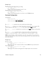
IOs and Waiting
You can insert other commands as well in sequence, such as waiting a certain amount of time (wait
milliseconds), changing outputs (io set do) or waiting for input conditions (wait io).
Example Usage:
Trajectory Control
28
Set digital output:
/01 stream 1 io set do 4 1↵
@01 0 OK IDLE -- 0
Digital output 4 is enabled at a point in the stream.
Wait for a certain amount of time:
/01 stream 1 wait 1000↵
@01 0 OK IDLE -- 0
Stream waits for 1000 ms at the point in the stream before continuing.
Wait for analog value to be above a certain value:
/01 stream 1 wait io ai 1 > 5↵
@01 0 OK IDLE -- 0
Stream will stop and wait until analog input 1 is above 5. Wait io commands will decelerate to a
stop because the input isn’t checked until after the last command is complete.
Communication Flow Control and Buffers
To ensure commands are executed continuously, the device can hold a queue of stream commands.
• Once the queue becomes full, the device cannot accept any more commands until some have finished
executing. If one is sent while the queue is full, it is rejected with the AGAIN message to indicate you
should resend the command until it is accepted. Sending again must be handled on the application
end.
• If the queue is almost empty, the movement will slow down and stop as the last available movement
command is finishes. As soon as it starts slowing down, it sets warning flag ND indicating there’s
been a discontinuity in the motion.
• You can fill up the queue before starting movement using the fifo cork command. It will
automatically start executing once the queue is full, or you can use fifo uncork to start before
then.
Instead of sending the stream commands while they are being executed (live mode), you can save a series of
stream commands to buffer locations on the device using the setup store command. After setting up the
stream in store mode, send the stream commands you’d like to save and then disable the stream. During a live
stream you’re able to execute those stored stream commands using the call command. Use the buffer
buf erase to clear the saved commands from the buffer location before saving to that location again. You
can display the sequence of stored commands with the buffer buf print command.
Example Usage:
Using cork to add commands to the queue:
/01
@01
/01
@01
/01
stream 1 fifo cork↵
0 OK IDLE -- 0
stream 1 line rel 5000 1000↵
0 OK IDLE -- 0
stream 1 line rel -5000 -1000↵
IOs and Waiting
29
@01 0 OK IDLE -- 0
/01 stream 1 fifo uncork↵
@01 0 OK IDLE -- 0
The line movements won’t be executed until uncork is sent or the queue is full.
Using cork while commands are currently executing:
/01 stream 1 fifo cork↵
@01 0 RJ BUSY ND BADCOMMAND
The cork command will be rejected if commands are already being executed.
Storing a command to run later:
/01 stream 1 setup store 3 2↵
@01 0 OK IDLE -- 0
/01 stream 1 line rel 10000 50000↵
@01 0 OK IDLE -- 0
/01 stream 1 setup disable↵
@01 0 OK IDLE -- 0
/01 stream 1 setup live 1 2↵
@01 0 OK IDLE -- 0
/01 stream 1 call 3↵
@01 0 OK IDLE -- 0
The line movement will execute after it buffer 3 is called in the live stream.
Clear a buffer:
/01 stream buffer 3 erase↵
@01 0 OK IDLE -- 0
Printing out the contents of a buffer:
/01 stream buffer 2 print↵
@01 0 OK IDLE WR 0
#01 0 setup store 2 2
#01 0 line abs 400000 500000
#01 0 io set do 4 1
#01 0 wait 100
#01 0 arc rel ccw 100000 -100000 200000 0
#01 0 setup disable
Replacing the #01 0 with /01 stream 1 in each line yields a sequence of commands that
perfectly reproduces the stored sequence when sent to another device (or the same device if the buffer
is erased first).
Printing an empty buffer:
/01 stream buffer 3 print↵
@01 0 RJ IDLE WR BADDATA
Buffer 3 was erased or was never used, so it cannot be printed.
Communication Flow Control and Buffers
30
Information
To read out information about a stream, use the stream info command. This command returns a list of
space-separated values which are, in order:
1. the stream mode (one of disabled, live, or store)
2. the axis count, or - if the stream is disabled
3. the maximum centripetal acceleration, or - if the stream is not in live mode
4. the maximum tangential acceleration, or - if the stream is not in live mode
5. the maximum speed, or - if the stream is not in live mode
6. an error reason indicating why flag FB was set, or - if FB was not set on this stream
The possible error reasons are:
axislimit
a motion tried to move the device beyond the positional limits
setting
a stream set tried to set a setting to an illegal value
stackdepth
stream operations were nested too deeply, most likely due to a buffers calling each other to too deep a
level
arcradius
an arc was not congruent to a circle, meaning that the arc’s “radius” was significantly different
between the start and end of the arc
bufempty
a stream call tried to call an empty buffer
buflocked
a stream call tried to call a buffer while it was being written to or erased
bufaxes
a stream call tried to call a buffer that was recorded with the wrong number of axes
system reset
Resets the device, as it would appear after power up.
Scope
Device
Parameters
none
Example Usage:
/system reset↵
@01 0 OK IDLE -- 0
system restore
Restores common device settings to their default values.
Information
31
Scope
Device
Parameters
none
This command resets common settings to their default for the device and peripheral. Communications settings
are not modified.
Example Usage:
/system restore↵
@01 0 OK IDLE -- 0
tools echo
Echoes the provided message (if any) back to the user.
Scope
Device
Parameters
[message]
This command always returns a successful response, with any message provided by the user.
Example Usage:
/tools echo hi there↵
@01 0 OK IDLE -- hi there
tools findrange
Uses the home and away sensors to set the valid range of the axis for the current session.
Scope
Axis
Parameters
none
This command replaces the home command on an axis equipped with both home and away limit sensors. The
axis is first homed and the current position set to limit.home.preset. If there is an away sensor present, the axis
is then moved to the away sensor. Once the away sensor is triggered, the limit.max setting is updated to the
current position for the current session.
This command is equivalent to the following set of commands issued in order:
tools gotolimit home neg 2 0 (or equivalently, home)
system restore
32
tools gotolimit away pos 1 1
NOTE: Upon power up or setting changes, this command should be issued to obtain a reference position and
valid range. Otherwise, motion commands may respond with a rejection reply or behave unexpectedly.
tools gotolimit
Moves the axis to a limit sensor and performs the provided actions.
Scope
Axis
Parameters
sensor direction action update
sensor specifies one of the limit switches to move to. Can be one of home, away, c or d.
direction specifies the travel direction to the sensor. Can be one of pos or neg for a positive or negative
direction of travel, respectively.
action specifies the action to perform when the sensor is triggered. This parameter shares the same values
and effects as the limit.sensor.action setting, except that it cannot be 0 (Disabled).
update how to update the sensor position setting. This parameter shares the same values and effects as the
limit.sensor.posupdate setting.
This command moves the axis in the direction specified and waits for sensor to trigger. The axis will then
align itself to the sensor edge specified by limit.sensor.edge and perform the limit switch action and position
update specified by action and update. limit.sensor.triggered is set to 1. If action is 2 (Retract and
update current position), the No Reference Position (WR) warning flag is cleared.
The automatic action settings as specified in limit.sensor.action and limit.sensor.posupdate are ignored.
Example Usage
Go home and reset the current position
/tools gotolimit home neg 2 0↵
@01 0 OK BUSY -- 0
Equivalent to the home command.
Adjust the effective travel range
/tools gotolimit away pos 1 1↵
@01 0 OK BUSY -- 0
Assuming that there is already a reference established, the command above leaves the current position
as it is when the away sensor it triggered. The limit.max setting is then updated to the current position.
tools findrange
33
tools parking
Parks the device.
Scope
Device
Parameters
state|park|unpark
Parking allows the device to be turned off and then used at a later time without first having to home the axes.
The parking state can be queried with the state option, returning 1 if parked or 0 if not.
A device can be parked with the park option. Once parked, any movement commands will result in a
PARKED error, except for home, which will home the respective axis and clear the parked state.
A parked device can be restored by powering it on and issuing the unpark command.
Example Usage:
Parking:
/tools parking park↵
@01 0 OK IDLE -- 0
Unparking:
/tools parking unpark↵
@01 0 OK IDLE -- 0
Parking when busy:
/tools parking park↵
@01 0 RJ BUSY -- STATUSBUSY
The device cannot be parked while it is busy.
NOTE: Parking should not be used when there is a load on the device that could cause it to slip when the
motor hold current is turned off.
tools setcomm
Sets the RS232 baud rate and communication protocol for RS232 and USB.
Scope
Device
Parameters
rs232baud protocol
tools parking
34
rs232baud specifies the desired RS232 baud rate. This parameter shares the same values as comm.rs232.baud.
protocol specifies the desired communication protocol, which must be supported on USB and RS232. This
parameter shares the same values as comm.rs232.protocol and comm.usb.protocol.
This command sets comm.rs232.baud, comm.rs232.protocol and comm.usb.protocol.
This command sets the Setting Update Pending (NU) notification flag and replies on the current
communication settings. Once all communication channels have been quiet for 500 milliseconds, the device
switches to the new settings and clears the Setting Update Pending (NU) flag.
Example Usage:
Switching RS232 baud rate and protocol:
/tools setcomm 9600 1↵
@01 0 OK IDLE NU 0
Configures the device to communicate at 9600 baud rate and in Binary protocol.
tools storepos
Stores a number of positions for axes for ease of movement.
Scope
Axis
Parameters
number [position|current]
number is the stored position number to be set or retrieved. The valid range is 1 - 16.
position is a valid axis position to move to and must be in the range of limit.min to limit.max. The position
defaults to 0 if not set.
current specifies that the specified stored position number be set to the current position, pos.
If none of the optional arguments are provided, the current value of the stored position number will be
returned.
Example Usage:
Storing a position:
/1 1 move abs 74920↵
/1 1 tools storepos 1 current↵
@01 1 OK IDLE -- 74920
Stores the current position of 74290 microsteps to position number 1 for axis 1.
tools setcomm
35
Setting a position:
/1 1 tools storepos 1 150000↵
@01 1 OK IDLE -- 0
Stored position 1 has been set to a position of 150000 microsteps for axis 1.
Retrieving a stored position:
/1 1 tools storepos 1↵
@01 1 OK IDLE -- 150000
The stored position 1 has a value of 150000 for axis 1.
Moving to a stored position:
/move stored 1↵
@01 0 OK BUSY -- 0
/get pos↵
@01 0 OK IDLE -- 150000 0
All axes on the device will move to their respective stored position. In the example above, axis 2
didn't have a value set for position 1 and moved to a position of 0.
trigger
Configures actions to be performed when an event is triggered.
Scope
Device
Parameters
info
show
number
number
number
number
enable [count]
disable
when condition configuration
action act command configuration
Triggers allow certain actions to be performed when an event occurs.
The trigger info command returns four values, the number of triggers in the device, the number of
available actions per trigger, the number of time triggers and the number of distance triggers. For example:
/1 trigger info↵
@01 0 OK IDLE -- 6 2 2 2
There are 6 triggers in total, each with 2 actions that can be performed. There are 2 time triggers available and
2 distance triggers available. In this case number has a range of 1 - 6 inclusive and act has a range of 'a' - 'b'
inclusive.
The trigger show command returns the state of the device triggers. For example:
tools storepos
36
/1 trigger show↵
@01 0 OK IDLE -- e d 500 d d d
Trigger 1 is enabled, trigger 3 will fire 500 more times before disabling and the rest of the triggers are
disabled.
The enable parameter turns on the specified trigger, executing the actions whenever the trigger fires. If the
count parameter is specified, the trigger action(s) are only performed count times. NOTE: The count
parameter itself is non-volatile but the value is not updated as the triggers fire. Upon reset, the value is
restored to the configured value, allowing the device to be configured and then powered off and installed
without a PC connection. The disable parameter turns off the specified trigger.
Note that the following settings either cannot be used in trigger conditions or actions, or can be used but have
special meanings:
• accel - Use motion.accelonly and/or motion.decelonly.
• comm.protocol - Use comm.rs232.protocol, comm.rs485.protocol, or comm.usb.protocol.
• driver.temperature
• peripheralid
• system.current
• system.temperature - Works, but measured in tenths of a °C when used in trigger conditions.
• system.voltage - Works, but measured in tenths of a volt when used in trigger conditions.
• version
Condition Configuration
Valid parameters
when io ao|ai|do|di chan trigger_condition value
when setting trigger_condition value
when axis setting trigger_condition value
Trigger Conditions
== Equal To
<> Not Equal To
< Less Than
> Greater Than
<= Less Than or Equal To
>= Greater Than or Equal To
The when io parameter sets a trigger to fire when a io type and channel compares to a provided value. The
available channels for each io type (ai|ao|do|di) can be queried with the io info command.
The when setting parameter sets a trigger to fire when a device setting compares to a provided value.
The when axis setting parameter sets a trigger to fire when a axis setting compares to a provided
value. The axis parameter indicates the axis number that the setting applies to.
Note that for firmware versions earlier than 6.11, not-equal-to must be written as != instead of <>.
trigger
37
Example Usage:
Triggering when an analog input exceeds a set voltage
/1 trigger 1 when io ai 2 > 7.5
@01 0 OK IDLE -- 0
Trigger 1 will fire when analog input 2 exceeds 7.5 volts.
Triggering when an axis position exceeds a value
/1 trigger 1 when 1 pos >= 750000
@01 0 OK IDLE -- 0
Trigger 1 will fire when the position of axis 1 hits or exceeds 750000 microsteps.
Command Configuration
Valid parameters
action
action
action
action
act
act
act
act
none
io do chan toggle|value
axis stop|move value
axis setting =|+= value
The action ... none parameter removes the specified action from the trigger.
The action ... io parameter sets a io digital output channel to the specified value, or toggles it. The
available channels for each io type (ai|ao|do|di) can be queried with the io info command.
The action ... stop|move parameter stops or performs one of the move commands on the specified
axis.
The action ... setting parameter adjusts a setting for the specified axis. The setting can be
configured to a certain value using the = option, or incremented by a set amount using the += option.
NOTE: No range checking or validity is performed on any of the value parameters. It is up to the user to
ensure that the provided value is always valid, otherwise the trigger will fail to carry out the desired action
under certain conditions.
Example Usage:
Moving to a position
/1 trigger 1 action a 1 move rel 10000
@01 0 OK IDLE -- 0
When trigger 1 fires, axis 1 of the device will move forward 10000 microsteps as the first action.
Toggle a digital output line
/1 trigger 1 action b io do 1 toggle
@01 0 OK IDLE -- 0
When trigger 1 fires, the device will toggle the state of digital output 1 as the second action.
Condition Configuration
38
Trigger Usage
The following examples demonstrate how to use the various trigger commands to perform actions.
Stopping when a digital input activates
The following commands will stop axis 1 when digital input 1 activates
/1 trigger 1
/1 trigger 1
/1 trigger 1
emergency stop
/1 trigger 1
when io di 1 == 1
action a 1 stop
action b 1 stopIf the second action is also stop, the device will perform an
enable
Cycling back and forth
The following commands will cycle axis 1 between 0 and 100000 microsteps. The maximum speed is
adjusted so that forward travel is twice as fast as backwards travel.
/1
/1
/1
/1
/1
/1
/1
/1
trigger
trigger
trigger
trigger
trigger
trigger
trigger
trigger
1
1
1
2
2
2
1
2
when 1
action
action
when 1
action
action
enable
enable
pos
a 1
b 1
pos
a 1
b 1
== 0
move abs 100000
maxspeed = 150000
== 100000
move abs 0
maxspeed = 75000
trigger dist
Toggles a digital output channel when the axis travels a certain number of microsteps.
Scope
Device
Parameters
number enable [count]
number disable
number axis interval
Once configured and enabled, the distance trigger will toggle a digital output channel every interval number
of microsteps. The trigger can be set up to fire a certain number of times by specifying the count parameter to
the enable command, otherwise it will fire until disabled.
The digital output channel that toggles is hard coded for each distance trigger. Trigger 1 on a device toggles
output 1, trigger 2 toggles output 2 and so on. The initial state of the channel can be set using the io set
command. The distance triggers will conflict with other commands that use the same digital outputs, resulting
in the state of the line changing arbitrarily.
Trigger Usage
39
Example Usage:
Set up the distance trigger 1 on axis 1 to toggle every 1000 microsteps and enable it.
/trigger
@01 0 OK
/trigger
@01 0 OK
dist
IDLE
dist
IDLE
1 1 1000↵
-- 0
1 enable↵
-- 0
trigger time
Toggles a digital output channel at a certain interval.
Scope
Device
Parameters
number enable [count]
number disable
number interval
Once configured and enabled, the time triggers will toggle the digital outputs every interval milliseconds.
Each trigger can be set up to fire a certain number of times by specifying the count parameter to the enable
command, otherwise they will fire until disabled.
The digital output channel is hard coded, where time trigger 1 toggles the last digital output, time trigger 2
toggles the second last output and so on. The initial state of the channel can be set using the io set command.
The time triggers will conflict with other commands that use the same digital output, resulting in the state of
the line changing arbitrarily.
Example Usage:
Set up time trigger 1 to toggle every 250ms (2Hz output rate) for 60 seconds (60/0.25 = 240 counts) and
enable it.
/trigger
@01 0 OK
/trigger
@01 0 OK
time
IDLE
time
IDLE
1 250↵
-- 0
1 enable 240↵
-- 0
warnings
Displays the active warnings for the device and axes.
Scope
Axis
Parameters
[clear]
trigger dist
40
Warnings prints out a 2 digit count of active warnings and then all the active warning flags, as described in
Warning Flags above. If this is sent to all axes on a device, the active warnings across all the axes will be
displayed, otherwise only the warnings for the specified axis will be displayed.
If the optional parameter clear is given, all the clearable warnings are reset.
Example Usage:
Normal response
/1 warnings↵
@01 0 OK IDLE -- 00
No warnings are active on the device
Axis warnings
/1 2 warnings↵
@01 2 OK IDLE FS 03 FS WD WR
There are 3 warnings active on axis 2, A stall fault, a displacement warning and a invalid reference
warning.
warnings
41
Device Settings
The following section covers all device settings that are available in the ASCII protocol, as such some of these
settings may not be available for a particular device. To see the available settings, consult the Device Settings
section of the product User Manual or the built-in help via: /1 help get↵.
All the settings listed below are used with the get and set commands to read and change their value. All
settings that can be modified require an integer value within the valid range. Some of the settings may return
dotted decimals or multiple values.
A get command on a setting that applies to an axis where a specific axis number has not been supplied will
result in a value being returned for each axis. For example, on a two axis device:
/1 get pos↵
@01 0 OK IDLE -- 10000 15000
Similarly, configuring an axis setting without specifying an axis number will result in the value being applied
to all axes on the device. For example, on a two axis device:
/1 set maxspeed 75000↵
@01 0 OK IDLE -- 0
/1 get maxspeed↵
@01 0 OK IDLE -- 75000 75000
If the specified value is outside the valid range for any axis, none of the axes will be set and a BADDATA
reply will be returned.
Settings labelled Read-Only cannot be configured and will reply with a BADCOMMAND error if the set
command is used with them. Configuring a setting with a value outside of its specified range will result in a
BADDATA reply.
For the default values of the settings please refer to the Device and Peripheral Pages for firmware 6.
accel
Determines the acceleration and deceleration used when changing speed.
Scope: Axis.
Valid Range: 0 - 32767.
Access Level: norm.
When a movement command is issued, the axis will increase and decrease its speed at a rate determined by
this setting. The actual acceleration is calculated as accel*10000/1.6384 microsteps/sec^2. A value of 0
specifies infinite acceleration.
To modify only the acceleration or deceleration see the motion.accelonly and motion.decelonly settings.
When queried, this setting returns the value of the acceleration setting, regardless of the deceleration setting.
Device Settings
42
cloop.counts
The number of encoder counts for a full revolution.
Scope: Axis.
Valid Range: 1 - 65535.
Access Level: adv.
Specifies the number of encoder counts used for the closed loop mode encoder count to motor step ratio.
This number is typically 4x the encoder lines per revolution.
cloop.mode
The closed loop control mode.
Scope: Axis.
Valid Range: 0 - 5.
Access Level: norm.
Valid settings are:
• 0 - Disabled.
Encoder input is ignored and the axis behaves as a open-loop device.
• 1 - Passive Mode.
Slip conditions are detected and cause the blue LED to blink, but no position correction is
made nor is a warning flag set.
• 2 - Stall Detection.
Same as passive mode but the axis will also detect and report stall conditions.
If a stall condition is detected the axis will stop after a stall timeout
• 3 - Position Correction (Default).
Axis detects, reports and recovers from slip conditions. Stall conditions are detected and
reported.
• 4 - Stall Recovery.
Same as Position Correction, however if stalling is detected, the axis will stop and resume
after a stall timeout.
• 5 - Displace Recovery
Same as Stall Recovery, however if a stationary axis is forced out of position, the axis will
restore to the original location after a timeout.
Closed loop mode can be enabled on devices with built-in encoder.
To use closed loop modes with a third party encoder, enable encoder.mode and configure all encoder related
settings. Set encoder.dir so that encoder.count increments in the same direction as pos. Adjust cloop.steps and
cloop.counts to reflect the correct ratio between motor full steps and encoder counts.
cloop.stalltimeout
Stall recovery time out.
cloop.counts
43
Scope: Axis.
Valid Range: 0 - 65535.
Access Level: norm.
Specifies, in milliseconds, the amount of time to wait after a stall/displacement condition before attempting to
recover from it for closed loop modes.
cloop.steps
Steps per revolution
Scope: Axis.
Valid Range: 1 - 255.
Access Level: adv.
Specifies the number of stepper motor full steps used for the closed loop mode encoder count to motor step
ratio.
This value is typically the number of full steps required for the motor to complete one revolution.
comm.address
The device address.
Scope: Device.
Valid Range: 1 - 99.
Access Level: norm.
The device will change its address and then respond when being set, e.g.:
/01 set comm.address 5↵
@05 0 OK IDLE -- 0
comm.alert
Alert Messages.
Scope: Device.
Valid Range: 0 - 1.
Access Level: norm.
The device sends Alert messages when this setting is 1.
comm.checksum
Send message checksums.
Scope: Device.
Valid Range: 0 - 1.
cloop.stalltimeout
44
Access Level: norm.
The device includes checksums in its messages if this setting is 1.
comm.protocol
The communications protocol used by the device on the current interface.
Scope: Device.
Valid Range: Refer to the protocol setting for the current interface.
Access Level: norm.
When writing to this setting, the device raises the Setting Update Pending (NU) notification flag and replies in
the current protocol. Once all the communications interfaces are idle, the device switches to the new protocol
and clears the Setting Update Pending (NU) flag.
comm.rs232.baud
The baud rate used by RS232 Prev and Next interfaces.
Scope: Device.
Valid Range: 9600 - 115200.
Access Level: norm.
Valid Settings:
• 9600
• 19200
• 38400
• 57600
• 115200.
All other serial parameters are 8 bits, 1 stop bit, No parity and no flow control.
When writing to this setting, the device raises the Setting Update Pending (NU) notification flag and replies in
the current baud rate. Once all the communications interfaces are idle, the device switches to the new baud
rate and clears the Setting Update Pending (NU) flag.
To set RS232 baud rate and protocol at the same time, use the tools setcomm command.
comm.rs232.protocol
The communications protocol used by the device on the RS232 Prev and Next interfaces.
Scope: Device.
Valid Range: See below.
Access Level: norm.
Valid settings are:
comm.checksum
45
• 1 - Binary Only.
Legacy T-Series binary protocol only.
• 2 - ASCII Only.
A-Series ASCII protocol only.
When writing to this setting, the device raises the Setting Update Pending (NU) notification flag and replies
over the current interface. Once all the communications interfaces are idle, the device switches to the protocol
on the specified interface and clears the Setting Update Pending (NU) flag.
comm.rs485.baud
The baud rate used by RS485 interface.
Scope: Device.
Valid Range: 1200 - 115200.
Access Level: advanced.
Valid Settings:
• 1200
• 4800
• 9600
• 19200
• 38400
• 57600
• 115200
All other serial parameters are 8 bits, 1 stop bit, No parity and no flow control.
When writing to this setting, the device raises the Setting Update Pending (NU) notification flag and replies in
the current baud rate. Once all the communications interfaces are idle, the device switches to the new baud
rate and clears the Setting Update Pending (NU) flag.
comm.rs485.enable
Enables the RS485 interface.
Scope: Device.
Valid Range: 0 - 1.
Access Level: advanced.
Setting to 1 enables the RS485 interface. If a lower priority interface is currently in use the device will
respond on the current interface and then switch to the RS485 interface, disabling the lower priority interface.
For the supported interfaces and their priorities, please consult the User Manual for your device.
When writing to this setting and the current interface is a lower priority then RS485, the device raises the
Setting Update Pending (NU) notification flag and replies on the current interface. Once all the
communications interfaces are idle, the device switches to the new interface and clears the Setting Update
Pending (NU) flag.
comm.rs232.protocol
46
comm.rs485.protocol
The communications protocol used by the device on the RS485 interface.
Scope: Device.
Valid Range: See below.
Access Level: advanced.
Valid settings are:
• 2 - ASCII Only.
A-Series ASCII protocol only.
When writing to this setting, the device raises the Setting Update Pending (NU) notification flag and replies
over the current interface. Once all the communications interfaces are idle, the device switches to the protocol
on the specified interface and clears the Setting Update Pending (NU) flag.
comm.usb.protocol
The communications protocol used by the device on the USB interface.
Scope: Device.
Valid Range: See below.
Access Level: norm.
Valid settings are:
• 1 - Binary Only.
Legacy T-Series binary protocol only.
• 2 - ASCII Only.
A-Series ASCII protocol only.
When writing to this setting, the device raises the Setting Update Pending (NU) notification flag and replies
over the current interface. Once all the communications interfaces are idle, the device switches to the protocol
on the specified interface and clears the Setting Update Pending (NU) flag.
deviceid
The device id for the unit.
Scope: Device.
Valid Range: Any value defined at Zaber Support - Device IDs.
Access Level: norm, Read Only.
The id specifying the model of the Zaber device. Each device and its associated id number is listed at Zaber
Support - Device IDs.
comm.rs485.protocol
47
driver.current.hold
Current used to hold the motor in position.
Scope: Axis.
Valid Range: 0 - 100.
Access Level: norm.
The hold current is applied when the axis is not in motion. The value of this settings is a percentage of the
maximum drive current of the axis (2.5A typically for A-Series devices).
driver.current.run
Current used to drive the motor.
Scope: Axis.
Valid Range: 0 - 100.
Access Level: norm.
The value of this setting is a percentage of the maximum drive current of the axis (2.5A typically for A-Series
devices).
driver.dir
The direction of motor driver output.
Scope: Axis.
Valid Range: 0 - 1.
Access Level: adv.
Inverts the output direction of the motor driver.
driver.temperature
The current temperature of driver, in degrees Celsius.
Scope: Axis.
Valid Range: 0 - 150.
Access Level: norm, Read-Only.
Example:
/1 1 get driver.temperature↵
@01 1 OK IDLE -- 53.5
The driver is currently at 53.5°C.
driver.current.hold
48
encoder.count
The position as reported by the axis encoder.
Scope: Axis.
Valid Range: -214783648 - 214783647.
Access Level: norm, Read-Only; adv, Read-Write.
The encoder count, where present. Units are arbitrary and dependent on the encoder used.
encoder.dir
The direction of encoder count.
Scope: Axis.
Valid Range: 0 - 1.
Access Level: adv.
Inverts the counting direction for the axis encoder.
encoder.filter
Enable and set up digital filtering of the encoder inputs.
Scope: Axis.
Valid Range: 0, 1, 2, 4, 16, 32, 64, 128, 256.
Access Level: adv.
A value of 0 disables filtering and any other value proportionally rejects noises while reducing the maximum
speed the encoder can update at.
encoder.index.count
The recorded counts of the axis encoder index pulse.
Scope: Axis.
Valid Range: -32768 - 32767.
Access Level: norm, Read-Only; adv, Read-Write.
For encoders that support an index pulse, this setting tracks the number of index pulses received.
encoder.index.mode
Specifies the operating mode of the encoder index pulse.
Scope: Axis.
Valid Range: 0 - 1.
Access Level: adv.
encoder.count
49
Valid settings are:
• 0 - Disabled.
No encoder index is present.
• 1 - Normal.
Encoder index pulses are counted.
encoder.index.phase
Specifies the value of the encoder phase for a valid index pulse.
Scope: Axis.
Valid Range: 0 - 1.
Access Level: adv.
When this setting is 0, the encoder index line needs to go high when both the encoder phase lines are low for
the index pulse to be counted.
When this setting is 1, the encoder index line needs to go high when both the encoder phase lines are high for
the index pulse to be counted.
encoder.mode
Specifies the operating mode of the encoder.
Scope: Axis.
Valid Range: 0 - 1.
Access Level: adv.
Valid settings are:
• 0 - Disabled.
No encoder is present.
• 1 - Normal.
The encoder input is enabled.
knob.dir
Knob movement direction.
Scope: Axis.
Valid Range: 0 - 1.
Access Level: norm.
Sets the movement direction for the knob. 0 and the device moves in a positive direction for clockwise
rotation. 1 reverses the direction.
encoder.index.mode
50
knob.distance
The distance moved via the knob.
Scope: Axis.
Valid Range: 0 - limit.max.
Access Level: norm.
Sets how far the axis moves with each step of the knob in displacement mode, in microsteps.
knob.enable
Enables the knob.
Scope: Axis.
Valid Range: 0 - 1.
Access Level: norm.
Enables the use of the knob when set to 1.
knob.maxspeed
The maximum speed that can be achieved with the knob in velocity mode..
Scope: Axis.
Valid Range: 1 - resolution*16384.
Access Level: norm.
When in velocity mode, the axis will move up to a maximum speed determined by this setting. The actual
speed is calculated as knob.maxspeed/1.6384 microsteps/sec.
knob.mode
Sets the mode of the knob.
Scope: Axis.
Valid Range: 0 - 1.
Access Level: norm.
Valid Settings:
• 0 - Velocity mode.
The knob controls the velocity of the axis, varying for the amount turned.
Velocity mode is defined by knob.speedprofile and knob.maxspeed setting.
• 1 - Displacement mode.
Each step of the knob moves the axis a specific distance, as indicated by the knob.distance
setting.
knob.distance
51
knob.speedprofile
Velocity increment profile.
Scope: Axis.
Valid Range: 1 - 3.
Access Level: norm.
Sets the profile to be used per increment when in velocity mode. Valid settings are:
• 1 - Linear
• 2 - Quadratic
• 3 - Cubic
limit.approach.accel
The acceleration to be used when approaching a limit sensor.
Scope: Axis.
Valid Range: 0 - 32767.
Access Level: adv.
When approaching a limit sensor, the axis will accelerate to limit.approach.maxspeed at the rate
specified. The actual acceleration is calculated as accel*10000/1.6384 microsteps/sec^2. A value of 0
specifies infinite acceleration.
limit.approach.maxspeed
The maximum speed to be used when approaching a limit sensor.
Scope: Axis.
Valid Range: 1 - resolution*16384.
Access Level: adv.
When approaching a limit sensor, the axis will travel at the lesser of limit.approach.maxspeed and maxspeed.
The actual speed is calculated as maxspeed/1.6384 microsteps/sec.
limit.detect.decelonly
The deceleration to be used when a limit sensor has been triggered.
Scope: Axis.
Valid Range: 0 - 32767.
Access Level: adv.
When a limit sensor is triggered, the axis will slow down to a stop at the rate specified. The actual
deceleration is calculated as decel*10000/1.6384 microsteps/sec^2. A value of 0 specifies infinite
acceleration.
knob.speedprofile
52
limit.detect.maxspeed
The maximum speed to be used when moving away from a limit sensor.
Scope: Axis.
Valid Range: 1 - resolution*16384.
Access Level: adv.
When a limit sensor is triggered, the axis will move away from the sensor at the speed specified.. The actual
speed is calculated as maxspeed/1.6384 microsteps/sec.
limit.swapinputs
Reverses the home and away sensor inputs.
Scope: Axis.
Valid Range: 0 - 1.
Access Level: adv.
Setting to 1 swaps the home and away input pins.
limit.sensor.action
Automatic limit switch action.
Scope: Axis.
Valid Range: 0 - 2.
Access Level: adv.
Specifies the automatic limit sensor action to be performed when sensor becomes active during axis
movement. The sensor is one of home, away, c or d. Valid setting are:
• 0 - Disabled.
No action is performed when this sensor is triggered.
• 1 - Retract.
Retract to the side of the sensor specified in limit.sensor.edge.
• 2 - Retract and update current position.
In addition to above, the value of limit.sensor.preset is written to pos. The No Reference
Position (WR) warning flag is cleared.
Sensor is active when limit.sensor.state is 1.
If an automatic limit sensor action is triggered and limit.sensor.triggered is 1, the Unexpected Limit Trigger
(WL) warning flag is set.
limit.sensor.edge
Specifies the side of the sensor for alignment during limit actions.
limit.detect.maxspeed
53
Scope: Axis.
Valid Range: 0 - 1.
Access Level: adv.
Specifies the side of the sensor to align with when the sensor is triggered. The sensor is one of home, away, c
or d.
A value of 0 aligns the axis with the positive side of the sensor, a value of 1 aligns with the negative side of
the sensor.
The positive and negative directions follow the orientation of the axis position.
limit.sensor.pos
The updated position of the sensor.
Scope: Axis.
Valid Range: -1000000000 - 1000000000.
Access Level: adv.
Can be updated to the current position of the sensor, depending on the setting of limit.sensor.posupdate. The
sensor is one of home, away, c or d.
The settings limit.home.pos and limit.away.pos have alternative names of limit.min and limit.max,
respectively. These two settings represent the boundary of pos and determine the valid travel range of the axis.
limit.sensor.posupdate
Specifies how to update the sensor position after an automatic limit switch action.
Scope: Axis.
Valid Range: 0 - 2.
Access Level: adv.
Specifies whether to update the sensor position setting after an automatic limit switch action. The sensor is
one of home, away, c or d. Valid setting are:
• 0 - Disabled.
The sensor position is not updated.
• 1 - Set to current.
The current position (pos) is written to limit.sensor.pos for this session only.
• 2 - Set to current and save.
The current position (pos) is written to limit.sensor.pos. The value of limit.sensor.pos is saved
to non-volatile memory and persists over power cycle.
The sensor position is updated after the automatic limit sensor action has been carried out. This setting has no
effect if automatic limit sensor action is disabled (limit.sensor.action is 0 (Disabled)).
If sensor is one of home or away, this mechanism affects the valid travel range of the axis. See limit.min and
limit.max.
limit.sensor.edge
54
limit.sensor.preset
The default position of the sensor.
Scope: Axis.
Valid Range: -1000000000 - 1000000000.
Access Level: adv.
Specifies the default position of the sensor, which can be used to update the current position, depending on the
limit.sensor.action setting. The sensor is one of home, away, c or d.
limit.sensor.state
The current state of the sensor.
Scope: Axis.
Valid Range: 0 - 1.
Access Level: adv, Read-Only.
This setting is 1 when the sensor is active, and 0 otherwise. The sensor is one of home, away, c or d.
If limit.sensor.type is 0 (Disabled), this setting is always 0.
limit.sensor.triggered
Whether the sensor has been triggered previously.
Scope: Axis.
Valid Range: 0 - 1.
Access Level: adv, Read-Only.
This setting is set to 0 at start up. The setting is set to 1 after a limit sensor command such as home, or an
automatic limit sensor action. The sensor is one of home, away, c or d.
If an automatic limit sensor action is triggered and this setting is 1, the Unexpected Limit Trigger (WL)
warning flag is set.
limit.sensor.type
The type of connected sensor.
Scope: Axis.
Valid Range: 0 - 2.
Access Level: adv.
Specifies the type of connected sensor. The sensor is one of home, away, c or d. Valid settings are:
• 0 - Disabled:
No sensor is connected.
limit.sensor.preset
55
• 1 - Active Low:
When active, the sensor outputs a logic low.
• 2 - Active High:
When active, the sensor outputs a logic high.
limit.max
The maximum position of the device, in microsteps.
Scope: Axis.
Valid Range: -1000000000 - 1000000000.
Access Level: norm.
Use this setting to limit the range of travel to a value other than the default. This setting is an alternative name
for the limit.away.pos setting.
NOTE: Exercise caution when modifying this setting, since it is possible to set the range to a value greater
than the physical limits of the axis.
limit.min
The minimum position the device can move to, measured in microsteps.
Scope: Axis.
Valid Range: -1000000000 - 1000000000.
Access Level: norm.
The range of travel ( limit.max - limit.min ) is axis dependent. This setting is an alternative name for the
limit.home.pos setting.
NOTE: Exercise caution when modifying this setting, since it is possible to set the range to a value greater
than the physical limits of the axis.
maxspeed
The maximum speed the axis moves at.
Scope: Axis.
Valid Range: 1 - resolution*16384.
Access Level: norm.
When a movement command is issued, the axis will move at a speed determined by this setting. The actual
speed is calculated as speed/1.6384 microsteps/sec.
motion.accelonly
Determines the acceleration used when increasing the speed.
limit.sensor.type
56
Scope: Axis.
Valid Range: 0 - 32767.
Access Level: norm.
When a movement command is issued, the axis will accelerate up to the maximum speed at a rate determined
by this setting. The actual acceleration is calculated as accel*10000/1.6384 microsteps/sec^2. A value of 0
specifies infinite acceleration.
motion.decelonly
Sets the deceleration used when slowing down.
Scope: Axis.
Valid Range: 0 - 32767.
Access Level: norm.
When a movement command is issued, the axis will decelerate at a rate determined by this setting. The actual
deceleration is calculated as decel*10000/1.6384 microsteps/sec^2. A value of 0 specifies infinite
acceleration.
peripheralid
The ID of the Zaber peripheral connected to a controller.
Scope: Axis.
Valid Range: Any of the values listed at Zaber Support - Peripheral IDs or 0.
Access Level: norm.
All Zaber peripheral IDs are specified at Zaber Support - Peripheral IDs.
pos
The current absolute position of the axis, in microsteps.
Scope: Axis.
Valid Range: limit.min - limit.max
Access Level: norm.
NOTE: Changing the value of this setting could result in the axis attempting to drive past its physical limits.
resolution
Microstep resolution.
Scope: Axis.
Valid Range: 1 - 256.
Access Level: norm.
motion.accelonly
57
Defines the number of microsteps per step of the motor. A typical A-Series motorized axis has 200 steps per
revolution and a default microstep resolution of 64, therefore it takes 12800 microsteps to make one full
revolution of the motor. For the parameters for a specific device, please refer to the device specific product
page at http://www.zaber.com/products.
NOTE: When the resolution is updated, the motion.accelonly, motion.decelonly, limit.min,
limit.max, limit.n.pos, limit.n.preset, knob.maxspeed, knob.distance, and
maxspeed settings are updated according to their default values and not their current values. After changing
this setting, the axis should be homed before any movement is performed.
stream.numbufs
Number of stream buffers.
Scope: Device.
Valid Range: 0 - 4.
Access Level: norm.
Reports the number of stream buffers provided on the device.
stream.numstreams
Number of streams.
Scope: Device.
Valid Range: 0 - 1.
Access Level: norm.
Reports the number of streams provided on the device.
system.access
Specifies the access level of the user.
Scope: Device.
Valid Range: 1 - 2.
Access Level: norm
Some commands require an access level of 'advanced' as they can potentially cause damage to the device and
stage. To use those commands and setting, system.access has to be set to access level 2.
system.axiscount
Reports the number of axes in the device.
Scope: Device.
Valid Range: 1 - 2.
Access Level: norm, Read Only
resolution
58
This setting reports the number of axes in the queried device.
system.current
The current being drawn by the device and motors.
Scope: Device.
Valid Range: 0 - 5.
Access Level: norm, Read-Only.
system.led.enable
Enables and disables the indicator LEDs.
Scope: Device.
Valid Range: 0 - 1.
Access Level: norm.
Setting to 0 disables all front panel LEDs on the device.
system.temperature
The current temperature of the unit, in degrees Celsius.
Scope: Device.
Valid Range: 0 - 150.
Access Level: norm, Read-Only.
Example:
/get system.temperature↵
@01 0 OK IDLE -- 26.8
The device is currently at 26.8°C.
system.voltage
The voltage being applied to the device.
Scope: Device.
Valid Range: 10 - 50.
Access Level: norm, Read-Only.
Example:
/get system.voltage↵
@01 0 OK IDLE -- 47.1
The device is currently receiving 47.1V from the supply.
system.axiscount
59
version
The firmware version of the device.
Scope: Device.
Valid Range: 6.0 - 6.99
Access Level: norm, Read-Only.
Example usage:
/get version↵
@01 0 OK IDLE -- 6.06
version
60
Checksumming
The Longitudinal Redundancy Check (LRC) is employed. This allows corrupted message detection but does
not provide error correction.
Devices will verify a message checksum if it appears in the message. Devices will only send checksums if the
comm.checksum variable is set to 1.
• A device will verify the checksum if the 3rd last character of a command (excluding footers) is a
colon.
• The colon is a reserved character for checksum indication and should not appear in the message data.
• The checksum is repesented as 2 hexadecimal characters, which are case insensitive.
• The checksum is calculated from the first byte after the message type. The leading /@!# of the
message is ignored.
If the checksum is invalid, the device will ignore the message and flash the yellow LED(s) until the next
command is received.
For example if the message is:
01 tools echo
the checksum is:
((48 + 49 + 32 + 116 + 111 + 111 + 108 + 115 + 32 + 101 + 99 + 104 + 111)
^ 0xFF) + 1 = ((1137 & 0xFF) ^ 0xFF) + 1 = 143 = 0x8F
and the final message is:
/01 tools echo:8F\r\n
Verification
To verify a message checksum the 8-bit sum of all the bytes in the message is calculated and added to the
transmitted checksum, which has been converted to an integer. The message is valid when the 8-bit result of
the sum is zero. The colon in the message is only used as a seperator and is otherwise ignored. Using the
example above:
(1137 + 0x8F) & 0xFF = 0
Example Code
The following examples show how to calculate a message checksum and verify a received message in several
languages.
C
Calculating a checksum
Checksumming
61
#define
#define
#define
#define
CSUM_NOTPRESENT
CSUM_NOSPACE
CSUM_FAIL
CSUM_OK
(-2)
(-1)
(0)
(1)
int csum_message(char *message, unsigned int max_length)
{
unsigned char c_sum = 0;
char *p = message+1;
//skip the type character
if(strlen(message) + 6 < max_length)
{
while(*p != 0x00)
{
c_sum += (unsigned char)*p++;
}
c_sum = ~c_sum + 1;
//is there room for the checksum?
//calculate the checksum
//negate
//add the checksum to the message
sprintf(p, ":%02X\r\n", c_sum);
return CSUM_OK;
}
return CSUM_NOSPACE;
}
Verifying a received message
int csum_verify(char *message)
{
unsigned char c_sum = 0;
char *p = message+1;
while(*p != 0x00)
{
c_sum += (unsigned char)*p++;
//skip the type character
//calculate the sum
if(*p == ':')
//found the checksum field, process
{
c_sum += strtol(++p, NULL, 16); //convert the sent checksum
return((c_sum == 0) ? CSUM_OK : CSUM_FAIL);
}
}
return CSUM_NOTPRESENT;
}
Python
Calculating a message checksum
def csum_message(msg):
c_sum = 0
for c in msg[1:]:
c_sum += ord(c)
c_sum = 256 - (c_sum & 0xFF)
return '%s:%02X\r\n' % (msg, c_sum)
#calculate the sum of the message to be transmitted
#take the ones compliment (negate)
#return the full message
Verifying a received message
def csum_verify(msg):
C
62
c_sum = 0
if msg.find(':') < 0:
return None
#return nothing if the checksum isn't present
x_msg, x_sum = msg.split(':', 1)
#seperate out the message and checksum
for c in x_msg[1:]:
c_sum += ord(c)
c_sum = (c_sum + int(x_sum, 16)) & 0xFF
#recalculate the sum of the received message
#add in the received checksum and truncate to a 8-bi
return (c_sum == 0)
#return true if the message passed checksum verifica
Python
63
Appendix A - Communication Software
Zaber Console
Zaber Console is the recommended application for controlling Zaber devices on Windows systems.
1. Download the Zaber Console and install it.
2. Launch Zaber Console
3. Select the serial port and protocol from the list and click Open
4. Zaber Console will automatically find and list the devices in the chain, as shown below.
◊ Using the Advanced tab, text commands can be sent to the device(s)
PuTTY
PuTTY, a terminal emulator, can be used to control Zaber devices in ASCII mode on Windows.
1. Download putty-0.62-installer.exe from
http://www.chiark.greenend.org.uk/~sgtatham/putty/download.html and install it
2. Launch PuTTY
3. Under the Terminal category:
♦ Set Local echo to Force on
♦ Set Local line editing to Force on
Appendix A - Communication Software
64
4. Under the Session category
♦ Set the connection type to Serial
♦ Set the speed to 9600
♦ Enter the COM port the device(s) are connected to. Typically COM1 if directly connected to
a computer, COM3 if using a USB adapter.
♦ Enter a connection description, Zaber Device Chain in this example, and click save. Next
time the connection can be opened by double-clicking on 'Zaber Device Chain' in the Saved
Sessions list.
5. Click Open. A window similar to the one shown below will appear. Send a command, in this case /,
and press enter. The device should respond as shown below.
PuTTY
65
◊ Send a test command to check the connection. In this case /help was sent and data was
received.
Minicom
Minicom is the recomended application for controling Zaber devices in ASCII mode on Linux.
1. Install Minicom using your distributions package manager, e.g. for Debian and Ubuntu:
sudo apt-get install minicom↵
2. Run Minicom from a terminal
3. Press Ctrl-A then O to open the options menu
♦ Select Serial port setup
◊ Set the serial device (A) to the correct device
◊ Set the baud rate (E) to 9600
◊ Disable hardware and software flow control (F, G)
◊ Press Enter to go back to the configuration menu
♦ Select Modem and dialing
◊ Clear out the Init and Reset strings (option A, B)
◊ Press Enter to go back to the configuration menu
Minicom
66
♦ Select Screen and keyboard
◊ Set Local echo (Q) to Yes
◊ Press Enter to go back to the configuration menu
♦ Save the setup as default
♦ Exit
4. Type a test command, in this example /, and press enter. The device should respond as shown below.
5. Minicom can be exited by pressing Ctrl-A then X.
Troubleshooting
• If no data is received from the device(s) check the following:
Troubleshooting
67
♦ The correct serial port and baud rate are being used. Refer to the device specific User Manual
for the correct settings.
♦ The devices are powered on. Each device should have a green light on the front panel.
♦ The devices are connected to the computer correctly.
Troubleshooting
68
Appendix B - Available Serial Ports
Finding Installed Serial Ports
Windows
1. Right click on Computer or My Computer and select Manage.
2. Select Device Manager from the Computer Management list
3. Expand the Ports (COM & LPT) category
♦ In this example there is one serial port installed (COM1), which is a USB adaptor.
Linux
1. Finding devices
♦ Open a terminal and execute the following command:
dmesg | grep -E ttyU\?S↵
♦ The response will be similar to the following:
[ 2.029214] serial8250: ttyS0 at I/O 0x3f8 (irq = 4) is a
16550A
[ 2.432572] 00:07: ttyS0 at I/O 0x3f8 (irq = 4) is a 16550A
[ 2.468149] 0000:00:03.3: ttyS4 at I/O 0xec98 (irq = 17) is a
16550A
[ 13.514432] usb 7-2: FTDI USB Serial Device converter now
attached to ttyUSB0
♦ This shows that there are 3 serial ports available: ttyS0, ttyS4 and ttyUSB0 (a USB adaptor)
2. Checking port permissions
Appendix B - Available Serial Ports
69
♦ Using the ports found above, execute the following command
ls -l /dev/tty{S0, S4, USB0}↵
♦ The permissions, given below, show that a user has to be root or a member of the dialout
group to be able to access these devices
crw-rw---- 1 root dialout 4, 64 Oct 31 06:44 /dev/ttyS0
crw-rw---- 1 root dialout 4, 68 Oct 31 06:45 /dev/ttyS4
crw-rw---- 1 root dialout 188, 0 Oct 31 07:58 /dev/ttyUSB0
3. Checking group membership
groups↵
♦ The output will be similar to the following:
adm cdrom sudo dip plugdev users lpadmin sambashare
Notice that dialout is not in the list
♦ A user can be added to the dialout group with the following command
sudo adduser $USER dialout↵
♦ Group membership will not take effect until the next logon.
Windows
70
Appendix C - Switching between Binary and ASCII
Protocols
If your device has firmware 6.06 or higher, it can be set to use either the Binary command protocol or the
ASCII command protocol. By default, all devices will start with the Binary protocol except the A-MCB2,
which starts with the ASCII protocol. We suggest using our Zaber Console software to configure which
protocol you would like to use, although the commands to configure will be available to any software.
Binary to ASCII
In order to change your device from Binary to ASCII, follow these steps:
1. Open Zaber Console.
2. Select the Binary version of the COM port the device is connected to from the Serial Port dropdown
and press Open.
3. Highlight the device you would like to change from the Device list.
4. Under the commands tab, select the Show All checkbox.
5. You should see the command Convert To Ascii (cmd 124). Enter a value of 115200 into the Data
field and press Send.
6. Close the Serial Port, change to the ASCII version of the COM port the device is connected to, and
press Open.
7. Confirm that the device is visible.
ASCII to Binary
In order to change your device from ASCII to Binary, follow these steps:
1. Open Zaber Console.
2. Select the ASCII version of the COM port the device is connected to from the Serial Port dropdown
and press Open.
3. Highlight the device you would like to change from the Device list.
4. Under the commands tab, select the Show All checkbox.
5. You should see the command 'tools setcomm'. Enter a value of '9600 1' into the Data field and press
Send.
Appendix C - Switching between Binary and ASCII Protocols
71
6. Close the Serial Port, change to the Binary version of the COM port the device is connected to, and
press Open.
7. Confirm that the device is visible.
Resetting to Default Protocol
If something happened when attempting the above that results in the device showing up in neither of the
ASCII or Binary port options in Zaber Console, you can reset the device to use the default by following these
steps:
1. Unplug the power supply of the device
2. Push the manual knob and hold it in
3. Plug in the power supply again while continuing to hold the knob in
4. Keep holding the knob in until the Blue LED is lit (~5 seconds), then release the knob.
If you're still unable to see the device, contact Zaber's technical support.
ASCII to Binary
72