1
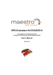
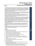
MN8010 Evaluation Kit
User Guide
1
Evaluation Kit Introduction
The MN8010 Evaluation Kit is designed to allow the user to quickly evaluate the Micro Modular
Technologies MN8010 GPS Receiver Module. The MN8010 Evaluation Kit implements the
necessary circuitry to attach a MN8010 GPS Receiver Module to a PC-compatible computer.
Primary power is supplied through the USB connector from the PC.
The MN8010 Evaluation Kit software is supplied on a CD ROM. This software is installed onto a
personal computer and allows the user to control the MN8010 GPS Receiver Module as well as
display and record the receiver output message data.
1.1
Document Applicability
This document applies to the MN8010 Evaluation Kit (MN8010-EVK).
1.2
Kit Identification
The version of the Evaluation Kit can be identified as follows: There is an MN8010 GPS Receiver
Module in the center towards the rear of the board and there are four LED indicator lights on the front
edge.
2
Description of the Evaluation Kit
The MN8010 Evaluation Kit features a USB translator from the logic levels utilized by the MN8010
GPS Receiver Module.
In addition, the MN8010 Evaluation Kit includes internal DC regulators which are used to provide the
necessary power to the MN8010 itself, as well as the ancillary circuitry on the MN8010 evaluation
board.
The MN8010 GPS Receiver Module includes a Real Time Clock (RTC) chip internally which provides
the receiver with precise time allowing it to execute a Hot Start (assuming that ephemeris and
position data is current). The user can therefore evaluate the Hot Start capability of the MN8010.
2.1
Supplied Equipment
The MN8010 Evaluation Kit contains the following items:
1. MN8010 GPS Receiver Module installed on the evaluation board which includes a USB
interface, power regulators, and switches.
2. MN8010 Evaluation Kit CD which contains the following:
a. Evaluation Software(SiRFLive) for operation of the MN8010 Evaluation Kit
b. Documentation for the MN8010 Evaluation Kit in PDF format.
3. A USB cable
4. An active antenna ( 22dB RF gain / 3.3V power input )
2.2
Additional Required Equipment
The MN8010 Evaluation Kit requires the following customer-supplied items at a minimum for testing
the MN8010 GPS Receiver Module: PC-compatible desktop or laptop (preferred) equipped with the
Windows operating system (XP, Vista or 7), one available USB port and a CD ROM drive.
Micro Modular Technologies Pte. Ltd.
No. 3, Ubi Avenue 3, #03-02 Crocodile House 408857 Singapore
Tel: 65-6745-8832 Fax: 65-6293-0661 Email: [email protected]
www.micro-modular.com
MN8010 Evaluation Kit
User Guide
3
Detailed Interface Description
3.1
Indicator Lights
Four indicator lights are provided on the faceplate to provide visual status of the MN8010 evaluation
board.
1. The leftmost light is the PWR light, which illuminates when DC power is active within the
MN8010 evaluation board.
2. The left-middle light is the DATA light, which flashes to indicate the MN8010 evaluation board is
sending serial data to the host computer. Note that this light will not flash unless the USB cable
is connected to a computer and an application program has opened the COM port.
3. The right-middle light is the 1PPS light, which flashes at a 1Hz rate driven by the 1PPS signal
from the MN8010 GPS Receiver Module. It is synchronized when the receiver has a valid fix
4. The rightmost light is the HIBERNATE light, which turns on when MN8010 GPS Receiver
Module goes into hibernate power state.
3.2
USB Serial Port
The USB Serial Port supports communications between the MN8010 evaluation board and the PCcompatible computer. Communications on this port use the National Marine Electronics Association
(NMEA)-0183 format or the SiRF One Socket Protocol (OSP, a super-set of SiRF Binary) for data
and command messages. The configuration (protocol, port speed, etc.) only can be changed by user
commands.
3.3
Antenna Connector
The SMA-type antenna connector provides the L1 GPS signal from an active antenna into MN8010
evaluation board. Refer to the description of jumper J4 for supplying power to the antenna. In case of
using a passive antenna or simulator, the receiver should be in HIGH GAIN mode. Note: Change of
Gain mode is only available in OSP message stream. To set the LNA Gain mode:
1. From the Commands menu of the SiRFLive, select IC Configuration; a dialog appears.
2. Click Advance. A warning dialog appears.
3. Click Yes to proceed. A second IC Configuration dialog appears.
4. Select the correct setting (HIGH GAIN) from the drop-down list and click OK.
5. From the Commands menu of the SiRFLive, select Reset; a Reset dialog appears.
6. Click on the Hot Start radio follow by the Send button to send a hot start command.
Note: MN8010 GPS receiver module is set to HIGH Gain mode by default to go with a passive
antenna or simulator, however the gain mode of the MN8010-EVK has been re-configured (patched
with a customized ROM patch version) to LOW Gain mode to go with an active antenna. The patch
is stored on external EEPROM by default.
3.4
Power Switch
The left (toggle) switch on the face of the MN8010 evaluation board is the power switch which
controls power to the evaluation board. If the switch is in the lower position, power is turned off to the
evaluation board. Note that the switch does not interrupt the DC power, but places the onboard
regulators into shutdown mode. Therefore, there is a very small amount of leakage current drawn
from the DC power source.
Micro Modular Technologies Pte. Ltd.
No. 3, Ubi Avenue 3, #03-02 Crocodile House 408857 Singapore
Tel: 65-6745-8832 Fax: 65-6293-0661 Email: [email protected]
Page 2 of 7
www.micro-modular.com
MN8010 Evaluation Kit
User Guide
3.5
nMR Button
The middle (pushbutton) switch, an active low Master Reset, is to reset MN8010 GPS Receiver
Module. This is for manufacturer (MMT) use only.
3.6
On-Off Button
The right (pushbutton) switch toggles the state of the GPS module between the On and Hibernate
states. By default from CSR, the MN8010 GPS receiver will always power up in Hibernate state and
needs to be waked up by sending an ON_OFF signal interrupt pulse from the host to activate the
receiver. An ON_OFF Pulse Generation Circuit is implemented on the Evaluation Board to activate
the receiver when the first power is applied. In the Hibernate state, RAM remains powered up and
the RTC continues running but the receiver itself does not operate, thus reducing power
consumption.
4
Configuring the Evaluation Kit
As shipped, the MN8010 Evaluation Kit is useable without having to re-configure internal options.
4.1
Jumpers
The J3 jumper block is prepared to provide +1.8V DC power for future use only. Leave the shunt off
for MN8010 GPS Receiver Module.
The J4 jumper block is used to provide +3.3V DC power for an active antenna. If an antenna or
antenna distribution system powered in some other fashion is to be used, then remove the shunt
across J4 to prevent possible damage to the MN8010 evaluation board.
The J5 jumper block is to enable U1 or U3 LDOs’ output. Shunt pin1-2 to enable +3.3V LDO output
(U3) for MN8010 GPS receiver module. Do not shunt Pin1-2. This is prepared for future use only.
The J6 jumper block is used to provide +3.3V DC power to the VBATT (main power) pin of the
MN8010 GPS Receiver Module.
The J7 header connector block provides access to some I/O signals of the receiver to read by
oscilloscope. Do not install any shunts on this header pins.
The J8 jumper block provides access to the 1PPS output signal. The right pin (viewed from the front)
is the 1PPS signal, and the left pin is ground. A shunt should NOT be installed.
The J9 jumper block is to connect +1.8V DC power rail from the VIO pin of MN8010 Receiver
Module to external devices which require +1.8V power supply. A shunt should normally be installed.
The J10 jumper block is used to control writing a serial EEPROM. Writing to the memory may be
inhibited if the /WC pin of the serial EEPROM is driven high, shunt J10.
Micro Modular Technologies Pte. Ltd.
No. 3, Ubi Avenue 3, #03-02 Crocodile House 408857 Singapore
Tel: 65-6745-8832 Fax: 65-6293-0661 Email: [email protected]
Page 3 of 7
www.micro-modular.com
MN8010 Evaluation Kit
User Guide
5
Setup and Initial Checkout of the MN8010 Evaluation Kit
Follow this procedure to initially check out the proper operation of the software and MN8010
Evaluation Kit hardware.
1. On the CD supplied with the Evaluation Kit, go to the “USB Driver” folder and run the program
“CDM 2.08.14.exe”. This will install the driver for the USB interface chip.
The link for the latest version of this driver is: http://www.ftdichip.com/Drivers/VCP.htm .
Choose the driver for the FT232R chip.
2. Install SiRFLive, which is the GPS evaluation program. Please refer to the SiRFLive User
Manual for details.
3. Connect the supplied USB cable from the MN8010 evaluation board to a USB port of the host
PC. The USB driver will provide a virtual COM port. You may use Windows’ Device Manager
to identify the COM port number assigned on your particular PC.
4. Place the antenna where it has a clear and unobstructed view of the open sky.
5. Start up the MN8010 evaluation program on the host computer and enable the connection.
Please refer to the SiRFLive User Manual for details.
6. Turn on the power switch of the MN8010 evaluation board and verify the power LED glows
green.
7. The MN8010 evaluation program should indicate communication with the MN8010 evaluation
board, and after a short delay of a minute or so display current time and position.
8. Allow the receiver to operate for approximately 15 minutes to collect current almanac data
from the GPS satellites.
Micro Modular Technologies Pte. Ltd.
No. 3, Ubi Avenue 3, #03-02 Crocodile House 408857 Singapore
Tel: 65-6745-8832 Fax: 65-6293-0661 Email: [email protected]
Page 4 of 7
www.micro-modular.com
MN8010 Evaluation Kit
User Guide
6
Evaluation Board Layout
Figure 1 – MN8010 Evaluation Board Layout
Micro Modular Technologies Pte. Ltd.
No. 3, Ubi Avenue 3, #03-02 Crocodile House 408857 Singapore
Tel: 65-6745-8832 Fax: 65-6293-0661 Email: [email protected]
Page 5 of 7
www.micro-modular.com
MN8010 Evaluation Kit
User Guide
7
Evaluation Board Schematic
Figure 2 – MN8010 Evaluation Board Schematic
Micro Modular Technologies Pte. Ltd.
No. 3, Ubi Avenue 3, #03-02 Crocodile House 408857 Singapore
Tel: 65-6745-8832 Fax: 65-6293-0661 Email: [email protected]
Page 6 of 7
www.micro-modular.com
MN8010 Evaluation Kit
User Guide
8
Notices
All reference and informational documents (including marketing information, specifications, reference
designs, etc.) are provided for information only and are subject to change without notice. Reasonable
efforts have been made in the preparation of these documents to assure their accuracy, however
Micro Modular Technologies Pte. Ltd. assumes no liability resulting from errors or omissions in this,
or any other document, or from the use of the information contained herein. Micro Modular
Technologies Pte. Ltd. reserves the right to make changes in the product design and specifications
as needed and without notification to its users. Please check our website for the most current
documentation. All information contained herein is the property of Micro Modular Technologies Pte
Ltd. and may not be copied or reproduced, other than for your information, without prior written
consent.
9
Contact Information
Email: [email protected]
www.micro-modular.com
For a list of Regional Sales Representatives,
please see our web page :
www.micro-modular.com
Asia & Corporate Headquarters
Tel: (65) 6745-8832
Americas and Europe
Tel: (1) 949-336-7850
Document no: MN8010-EVK_UG_110412
Micro Modular Technologies Pte. Ltd.
No. 3, Ubi Avenue 3, #03-02 Crocodile House 408857 Singapore
Tel: 65-6745-8832 Fax: 65-6293-0661 Email: [email protected]
Page 7 of 7
www.micro-modular.com