1
B-sensor User Manual
v1.5 5-April-2001
2 How it works
2.1
Description
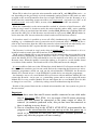
Figure 2 below shows schematically a setup between a controlling system and two B-sensor
modules, with only the SPI and microcontroller/ADC interconnection shown.
B-sensor
B-sensor
CRYSTAL
CS5524
24-bit ADC
CRYSTAL
CS5524
24-bit ADC
ACS_
ACS_
SDO
ENA
Controlling
System
(e.g. PC or
µC)
SDI SCLK SDO
SDO
ENA
Atmel
µC
SDI SCLK SDO
CS
Atmel
µC
CS
CS
SDO
SCLK
SDI
Figure 2. A system with two B-sensor modules connected to one SPI interface.
If the microcontroller is present, the CS signal serves to select between microcontroller and
ADC, although an ADC is only accessible after a successful selection protocol with the microcontroller (the microcontroller is in control of the ADC chip-select signal ACS_ ). The
syntax and workings of the selection protocol are explained in the next sections of this document.
(If the microcontroller is not installed some extra resistors have to be mounted, causing CS
to be connected directly to ACS_ so that the controlling system directly controls the ADC
chip-select; also the SDO enable/disable circuit is circumvented. In this case only one Bsensor module can be connected to the SPI interface of the controlling system ! (unless multiple chip-select signals are provided)).
In the rest of this document we assume the microcontroller is present and programmed !
At power-up the B-sensor module goes into the following state: the ADC is not selected
(ACS_ is high) and SDO output (from the ADC) is not enabled (SDO_ENA is low) and the
microcontroller is idle.
Now when CS transitions from low to high the microcontroller wakes up and is ready to receive commands via SDI (clocked via SCLK). So the microcontrollers from all SPI connected B-sensor modules are now listening to the data on the SPI bus.
3