1
v2.1 14-Jan-2000
SPICAN CANopen
SPICAN
CANopen I/O-system
(for analog inputs)
(applies to SPICAN, CRYSTAL-CAN and CRYSTAL-CAN-2 modules
with SPICAN CANopen firmware)
H. Boterenbrood
NIKHEF, Amsterdam
January 2000
USER DOCUMENTATION Version 2.1
ABSTRACT:
This document describes the SPICAN system of controller and signal-conditioning module(s) (e.g T-SENSOR) in combination with CANopen application firmware for monitoring
up to 192 analog input channels.
The CRYSTAL-CAN hardware is electronically almost identical (CRYSTAL-CAN-2 is
electronically fully identical) to SPICAN and the same CANopen firmware (with some limitations in case of CRYSTAL-CAN) is available for these systems.
1
v2.1 14-Jan-2000
SPICAN CANopen
Contents
TECHNICAL SPECIFICATIONS ......................................................................................... 2
1
INTRODUCTION.............................................................................................................. 3
2
OPERATION...................................................................................................................... 5
2.1
2.2
2.3
2.4
2.5
2.6
2.7
2.8
3
INITIALISATION............................................................................................................... 5
READING ANALOG INPUT CHANNELS ............................................................................. 5
OVER-LIMIT NOTIFICATION............................................................................................ 7
SETTING UPPER LIMITS .................................................................................................. 8
STORING PARAMETERS ................................................................................................. 10
ADC RESET AND CALIBRATION ................................................................................... 11
ADC CHANNEL NUMBERING SCHEME.......................................................................... 11
EMERGENCY OBJECTS .................................................................................................. 12
OBJECT DICTIONARY................................................................................................. 13
REFERENCES........................................................................................................................ 20
APPENDIX A LEDS, SWITCHES AND JUMPERS ......................................................... 21
APPENDIX B CONNECTOR LAYOUT ............................................................................ 22
Technical Specifications
SPICAN controller module:
• microcontroller: Philips P80C592 8-bit @ 16 MHz
• in-system-programmable via RS232 port
(available user memory: 63.5 kByte flash-ROM, 48 kByte RAM)
• power requirement: ca. 200 mA @ +5V
• firmware versions SPICAN v4.0 and up:
CANopen device profile according to CiA DSP-401, CAN node-id between 1 and 127,
CAN baudrate 125 or 250 kbit/s, minimum boot-up, default CANopen COB-ID distribution, 192 analog inputs mapped to up to 6, 12 or 24 ADCs, over-limit interrupt on first 64
channels (can be extended to all 192 channels), control and configuration of individual
ADCs, non-volatile storage of parameters and settings
T-SENSOR module:
• 30 NTC-sensor inputs
• operating range: 0°-100°C
• power requirement: ca. 1.5 mA @ +5V
• conversion table ADC-count → temperature provided (in ASCII-format)
• accuracy: 0.3°C (0.1°C calibration precision + 0.2°C spread in NTC sensor
(DC95-F-503-W, 5kΩ)
• resolution: ranging from ca. 1m°C at 5°C to 25m°C at 100°C
• drift: 1m°C/°C when regularly applying calibration (e.g. once per hour), otherwise 5m°C/°C
2
v2.1 14-Jan-2000
SPICAN CANopen
1 Introduction
From a hardware point-of-view the SPICAN system is a modular CAN-node consisting of a
controller card and one or more I/O-cards or -modules which are controlled and read out via a
serial connection (SPI or MicroWire type).
The controller card (Eurocard format) contains the microcontroller and CAN-interface. It is
built around a 16-MHz Philips 80C592 8-bit microcontroller with on-chip CAN controller. It
provides 48 kByte of user program memory and 63.5 kByte of user RAM [1]. Program code
(in standard Intel Hex format) can be downloaded directly via the RS232 port.
A T-SENSOR I/O-card (Eurocard format) has been developed, suitable for connecting 30
NTC-sensors. The T-SENSOR card is built around the 16-bit CS5525 ADC [2], which is controlled through a 3-wire serial interface (SPI).
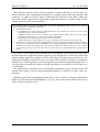
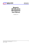
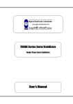
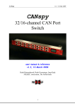
The SPICAN controller card has been designed specifically to control any number of SPIcontrolled I/O modules that it can select individually using an 8-bit select-port, as shown in
Figure 1. SPI (Serial Peripheral Interconnect) is a simple serial point-to-point connection between devices. There are many types of chips with SPI-like interfaces available on the market.
SPI
SDI
SDO
SCLK
8
ChipSelect
signals
CAN-bus
SPICAN
controller
module
CSx
CSy
CS5525
ADC
CS5525
ADC
signal
conditioning
module
signal
conditioning
module
etc.
19" crate
Sensors
Sensors
Figure 1. SPICAN system.
3
v2.1 14-Jan-2000
SPICAN CANopen
Apart from the signals used to control a number of external SPI-devices several other signals provided by the on-board microcontroller are available on the SPICAN controller card
connector, e.g. eight 10-bit ADC inputs (connected to the 80C592 on-chip ADC). These signals can be used by applications if appropriate application software is written, using a development toolset for 8051 microcontrollers.
The hardware differences between the SPICAN system and the CRYSTAL-CAN module with its matching
T-sensor and B-sensor conditioning modules are:
♦ the mechanical format
A CRYSTAL-CAN node consists of individual boxes: one controller box and one or more signalconditioning boxes, connected by flatcable.
A SPICAN node consists of one controller card (single Eurocard format) and one or more signalconditioning cards sitting in a 19' crate, connected via a backplane.
A CRYSTAL-CAN node must get its power via the CAN cable.
A SPICAN node has a power-supply in its crate or optionally can be powered via the CAN cable.
♦ the SPICAN controller card contains an EEPROM for storing settings and configuration data; the CRYSTAL-CAN is not equipped with an EEPROM so that settings/configurations cannot be stored; if settings
different from the power-on default are required on the CRYSTAL-CAN node they have to be reconfigured at every power-up/reset of the node (or the controller has to be reprogrammed to use appropriate defaults).
Of course it is the software that determines the functionality of this device and this document describes the application firmware that has been developed for a SPICAN system with
multiple analog inputs from multiple CS5525-ADC-based I/O-cards. It can monitor up to 192
analog input channels connected to up to 24 Crystal CS5525 ADCs. It features a mechanism
whereby up to 64 analog inputs are checked against a per-channel-configurable upper limit. A
CAN-message is generated if a limit is crossed (from under- to overlimit as well as from overto underlimit).
This application is currently in use for monitoring temperature sensors, B-field sensors and
voltages and currents; only the signal-conditioning hardware is different in each of these applications.
Monitoring and other communication takes place via the CAN-bus, using the standardized
high-level CAN-bus protocol CANopen ([3], [4], [5]). For a concise description and overview
of the CANopen protocol see [6].
4
v2.1 14-Jan-2000
SPICAN CANopen
2 Operation
The following sections show examples of the (CANopen) CAN-messages required to control
and operate a SPICAN (or CRYSTAL-CAN) system.
In the examples below the following assumptions are made:
CAN Node-ID of the controller is 5.
two ADCs are connected (i.e. two T-SENSOR modules)
each ADC serves 32 input channels (the last two of which are the 100°C and 0°C calibration inputs), but the number of used ADC channels has been set to 30 (thus skipping
read-out of the calibration inputs).
2.1
Initialisation
After power-up, watchdog reset, manual reset or CANopen initiated reset actions the SPICAN node sends a so-called Bootup message (defined by the CANopen standard) as soon as it
has finished its initialization; this is a CAN-message with the following syntax:
SPICAN (NMT-Slave)
→
Host (NMT-Master)
COB-ID
0x700 + Node_ID
Byte 0
0
In case of a watchdog or manual reset the Bootup message is followed by a CANopen Emergency message, as listed in the table in section 2.8.
2.2
Reading Analog Input Channels
Before any input channels can be read the connected CANopen-nodes have to be set into
Operational state using the following 2-databyte NMT message:
Host (NMT-Master) → SPICAN (NMT-Slave)
COB-ID
0x000
Byte 0
1
(Start_Remote_Node)
Byte 1
5 (Node-ID)
or 0 (all nodes)
There is no reply to this message.
The analog inputs are read out using the CANopen PDO mechanism. A PDO message is a
non-confirmed CAN-message with one sender and one or more receivers, containing no protocol overhead, only data (1 to 8 bytes). It is assumed that receivers of a PDO message know
the meaning of the data content of a PDO message.
The SPICAN application uses a PDO containing 4 bytes for every analog input. The CANidentifier used for this PDO is the socalled 2nd-transmit-PDO of the CANopen Predefined
Connection Set, which is the default PDO used for analog inputs according to CANopen
(meaning COB-ID = 0x280 + Node_ID).
5
v2.1 14-Jan-2000
SPICAN CANopen
Node 5 will produce the following 4-databyte PDO:
SPICAN (node #5) → Host
COB-ID
Byte 0
0x285
Channel Number
Byte 1
Channel status
Byte 2-3
ADC value
with:
Channel Number: runs from 1 to 30 and from 33 to 62 (skipping the calibration inputs at
channel 31+32 and at 63+64, if the node is configured as described earlier)
Channel status: 0xf0: OKAY; 0xf1, 0xf2, 0xf3, 0xff: ERROR.
ADC value:
16-bits value, LSB in byte 2, MSB in byte 3 (ADC value 0x8000 in combination with channel status 0xf1 means no sensor is connected to the
particular input)
The way in which all 60 analog inputs of the example CAN-node can now be read out depends on the transmission-type of the PDO. The user reads out the analog inputs according to
the PDO transmission-type the node has after power-up. Alternatively the user can set the
transmission-type to the required value by writing to the node’s Object Dictionary (OD index
0x1801, subindex 2, see Table 2), and possibly stores it onboard so that it will be the default
transmission-type after every subsequent reset or power-up.
The following transmission-types are supported:
•
PDO transmission type = 1:
after every socalled SYNC message issued on the CAN-bus the node sends 60 PDO
messages, one message for every (configured) analog input channel.
If the PDO’s inhibit time is > 0 (OD index 0x1801, subindex 3) the PDOs containing locally stored conversion values will be sent in quick succession. If the PDO’s inhibit time
is equal to zero, a conversion has to be done for every channel so it can take up to several seconds before all PDOs have been sent (the ADC conversion rate can be as low as
3 Hz).
The SYNC message is a CAN-message with a fixed COB-ID and no data bytes:
Host
→
all (SYNC-)slave nodes
COB-ID
0x080
Note that all nodes configured to respond to a SYNC will react to a SYNC message.
•
PDO transmission type = 253:
after every socalled Remote Transmission Request (RTR) for the PDO the node sends
60 PDO messages, one message for every (configured) analog input channel. Concerning
the PDO’s inhibit time the same applies as for transmission-type 1 (see above).
The CAN Remote Frame that constitutes the RTR has no data bytes and looks like this:
Host
→
SPICAN (node #5)
COB-ID
0x285 (0x280+Node_ID)
6
v2.1 14-Jan-2000
SPICAN CANopen
Note that an RTR is sent to and received by only one particular node.
•
PDO transmission type = 254:
same as transmission-type 253, except when the PDO’s inhibit time is > 0 (OD index
0x1801, subindex 3), because then the node autonomously scans its analog input channels
(with a frequency -per ADC- determined by the inhibit time) and a PDO is sent after every
completed conversion. So after the node has been set into Operational state it continuously sends PDO messages. This can be stopped by putting the node into Pre-operational
state: send an NMT message (see above) with byte 0 = 128 (‘Enter Pre-operational state’).
For all supported transmission types, assuming the SPICAN controller module is continuously scanning its analog input channels (i.e. inhibit time > 0, OD index 0x1801, subindex 3),
the ADC value retrieved is the locally stored value of the last conversion of that channel. With
a conversion frequency of 10 Hz (per ADC) and 30 input channels (per ADC) the last conversion could be up to 3 seconds 'old'; how old exactly is not known. If this is undesirable, the
user should set the inhibit time to zero; a conversion is then started only after a request has
been received (either through a SYNC or an RTR message).
For completeness it should be mentioned that individual analog input channels can –at any
time– also be read out by reading the corresponding Object Dictionary entries (OD index
0x6404, see Table 3), using the CANopen SDO mechanism. Whether a locally stored value is
retrieved or an analog-to-digital conversion takes place, again depends on whether the node is
continuously scanning its input channels, or not.
2.3
Over-Limit Notification
Upper limits are implemented for the first 64 analog input channels (firmware versions 4.0
and up). How to set the limits is described in the next section. When a channel’s ADC count
exceeds its upper limit a PDO message is generated by the controller; when the count goes
again below the upper limit another PDO message is generated. (To be implemented(?): However, when the upper limit is exceeded it is temporarily decreased by 16 ADC-counts to add
some hysteresis in order to prevent an unstable 'on/off' condition).
The PDO message contains the upper-limit state of 64 channels. It is possible that one PDO
notification message contains a state change for more than 1 channel, so all 64 bits in the message have to be checked by the receiver of the PDO.
The upper-limit interrupt mechanism is active when the analog channels are scanned periodically by the controller (to be set in OD index 0x1801, subindex 3: 2nd-transmit-PDO inhibit time) and the interrupt is enabled (in OD index 0x6423).
A special version of the SPICAN application firmware has been made for monitoring LowVoltage powersupplies in the HERMES experiment. In this system there are 24 ADCs with 8
multiplexed analog inputs each, monitoring voltage, current and temperature; in the over-limit
check of this application only one of the inputs of each ADC is considered (this is a temperature-sensor input). If an over-limit situation is detected one of the CS5525 ADC's output signals is set, which in this particular system causes the powersupply to be switched off.
So in this application, although there are a total of 192 input channels, there are only 24
channels that have an upper-limit and over-limit check.
7
v2.1 14-Jan-2000
SPICAN CANopen
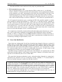
The 1st-transmit-PDO message generated (COB-ID = 0x180 + Node_ID) contains 8 data
bytes with the following syntax:
SPICAN (node #5) → Host
COB- Byte
ID
0
1
2
3
4
5
6
0x185
ch1-8
ch9-16 ch17-24 ch25-32 ch33-40 ch41-48 ch49-56
limit
limit
limit
limit
limit
limit
limit
status
status
status
status
status
status
status
7
ch57-64
limit
status
with a bit set to ‘1’signifying the upper limit has been exceeded by the corresponding channel.
Within a byte, channels are mapped as follows (1 bit per channel):
Bit
7
ch #n+7
2.4
6
ch #n+6
5
ch #n+5
4
ch #n+4
3
ch #n+3
2
ch #n+2
1
ch #n+1
0
ch #n
Setting Upper Limits
At power-on or reset the upper limits for the analog channels are read from the onboard
EEPROM if valid data is found there, otherwise the limit is set to the maximum ADC value
(32767).
The analog inputs upper limits can be read and written by accessing OD index 0x6424 using
the CANopen SDO mechanism.
Note that the interrupt message feature (using the 1st-transmit-PDO) is currently only implemented for channels 1 to 64! (Enabling this for more channels requires the addition/implementation in the controller firmware of one PDO for every additional block of 64
channels).
Reading the upper limit of channel #3 requires the host to send the following message (OD
index in byte 1+2, subindex in byte 3):
Host
→
SPICAN (node #5)
Byte
COB-ID
0
1
0x605
0x40
0x24
2
0x64
3
0x03
4
–
5
–
6-7
–
5
0x12
6-7
–
Assuming the upper limit is equal to 0x1234, the controller will reply with:
SPICAN (node #5) → Host
Byte
COB-ID
0
1
0x585
0x4B
0x24
2
0x64
3
0x03
8
4
0x34
v2.1 14-Jan-2000
SPICAN CANopen
Setting the upper limit of channel #3 to 0xABCD requires the host to send the following
message:
Host
→
SPICAN (node #5)
Byte
COB-ID
0
1
0x605
0x2B
0x24
2
0x64
3
0x03
4
0xCD
5
0xAB
6-7
–
2
0x64
3
0x03
4
–
5
–
6-7
–
The controller will reply with:
SPICAN (node #5) → Host
Byte
COB-ID
0
1
0x585
0x60
0x24
The upper limit of all channels can be set to the same value by writing the limit value to
channel number 0xFF (SDO message databyte 3).
In general an upper limit is read like this:
Host
→
SPICAN
Byte
COB-ID
0
0x600 +
0x40
Node_ID
SPICAN
0x580 +
Node_ID
1-2
Object
Index
(0x6424)
3
Object
Subindex
(channel)
Object
Index
(0x6424)
Object
Subindex
(channel)
4
–
5
–
6-7
–
→ Host
0x4B
ADC value
(LSB first)
–
In general an upper limit is set like this:
Host
→
SPICAN
Byte
COB-ID
0
0x600 +
0x2B
Node_ID
SPICAN
0x580 +
Node_ID
1-2
Object
Index
(0x6424)
3
Object
Subindex
(channel)
4
Object
Index
(0x6424)
Object
Subindex
(channel)
–
5
6-7
–
–
–
ADC value
(LSB first)
→ Host
0x60
9
v2.1 14-Jan-2000
SPICAN CANopen
2.5
Storing Parameters
Parameters and settings can be stored permanently onboard (in an EEPROM) by writing the
string "save" to OD index 0x1010. Again the CANopen SDO mechanism is used to do this:
Host
→
SPICAN (node #5)
Byte
COB-ID
0
1
2
0x605
0x23
0x10
0x10
3
subindex
4
0x73
('s')
5
0x61
('a')
6
0x76
('v')
7
0x65
('e')
with OD index 0x1010 in byte 1+2 and subindex in byte 3 with subindex:
=1: store all parameters (as listed for subindex 2, 3 and 4).
=2: store communication parameters, i.e. OD index 0x1801 (subindex 2,3).
=3: store analog channels upper limits, i.e. OD index 0x6424 (subindex 1 to 192).
=4: store ADC configurations, i.e. OD indices 0x2A00 to 0x2A18 (subindex 1 to 4),
0x2B00 to 0x2B18 (subindices 2 to 5), 0x2F00, 0x2F10 and 0x6423.
If the store-operation succeeded the controller sends the following reply:
SPICAN (node #5) → Host
Byte
COB-ID
0
1
0x585
0x60
0x10
2
0x10
3
subindex
4
–
5
–
6-7
–
If the store-operation did NOT succeed the controller sends the following reply (SDO Abort
Domain Transfer, error reason: ‘hardware fault’ (for details see [6])):
SPICAN (node #5) → Host
Byte
COB-ID
0
1
2
0x585
0x80 0x10 0x10
3
subindex
4
0
5
0
6
6
(Error Code)
7
6
(Error Class)
Parameters can be reset to their default values (by invalidating the corresponding contents of
the EEPROM) by writing to OD index 0x1011, using this time the string "load" (0x6C, 0x6F,
0x61, 0x64) in bytes 4 to 7 of the SDO. Note that the default values take effect only after a
subsequent reset of the node. Default values are listed in the OD tables in section 3.
10
v2.1 14-Jan-2000
SPICAN CANopen
2.6
ADC Reset and Calibration
At every power-on the controller (including its CAN-interface) and connected ADCs are reset, configuration parameters are read from EEPROM (if valid) and a calibration sequence is
performed on all connected ADCs.
The following NMT message with command Reset_Node causes a full reset of the node including a reset and calibration sequence for all connected ADCs:
Host (NMT-Master) → SPICAN (NMT-Slave)
COB-ID
0x000
Byte 0
129
(Reset_Node)
Byte 1
5 (Node-ID)
or 0 (all nodes)
In addition, it is possible to perform a reset and calibration sequence on an individual ADC
by writing the number of the ADC to be reset to OD index 0x2C00 (using the SDO mechanism). See OD Table 5.
2.7
ADC Channel Numbering Scheme
At maximum 192 analog input channels are supported. These can be divided over a number
of ADCs. The range of channel numbers reserved for one ADC is set in OD index 0x2F10
(this number has to be one of 8, 16 or 32, for reasons of computational convenience...). E.g. if
set to 16 ADC#0 carries channel numbers 1 to 16, ADC#1 channels 17 to 32, etc etc., and
ADC#12 channels 177 to 192. If set to 8, ADC#0 carries channels 1 to 8, ADC#1 channels 9
to 16, etc etc., and ADC#23 channels 185 to 192.
In OD index 0x2F00 can be set, up to which ADC number is actually in use; it is not necessary to set this parameter because the node detects which ADC numbers are connected and
which are not (and skips these when initiating conversions). Setting this parameter properly,
can speed up some of the node's actions.
The number of channels actually in use for each individual ADC can be set in the ADCconfiguration object in OD index 0x2Ann, subindex 1; when the SPICAN controller scans the
analog inputs, conversions are only performed for the set number of inputs.
Configuring the settings for a particular system is typically done just once (probably offline),
after which the settings are stored onboard. This enables flexible interfacing to systems with
different and variable numbers of CS5525-ADC based modules.
(NB: if settings cannot be stored because no EEPROM is present a customized firmware
version can be made with default settings to match the application).
11
v2.1 14-Jan-2000
SPICAN CANopen
2.8
Emergency Objects
Emergency messages are triggered by the occurrence of a SPICAN internal (fatal) error
situation. An emergency message has the following general syntax:
SPICAN → Host
COB-ID
Byte 0-1
0x080 +
Emergency
Error Code
Node_ID
Byte 2
Error Register
(Object 0x1001)
Byte 3-7
Manufacturer specific error field
The following Emergency messages are defined for SPICAN:
Emergency
Error Code
Error Register
(byte 0-1)
(byte 2)
Watchdog or
manual (frontpanel) reset
0x6000
0x01
Byte 3,4,5,6: Manufacturer Device Name
(Object Dictionary index 0x1008)
Byte 7: 0
CAN-controller
overrun: message lost
0x8100
0x10
CAN-controller
error:
communication
error
Local CAN
message buffer
overflow:
message lost
0x8100
0x10
0x8100
0x10
Byte 3: 1
Byte 4: counter (modulo 256)
Byte 5: CANSTA (CAN-controller status register)
Byte 6,7: 0
Byte 3: 2
Byte 4: counter (modulo 256)
Byte 5: CANSTA (CAN-controller status register)
Byte 6,7: 0
Byte 3: 3
Byte 4: counter (modulo 256)
Byte 5: CANSTA (CAN-controller status register)
Byte 6,7: 0
EEPROM:
write failed
EEPROM: read
CRC error
0x5000
0x80
0x5000
0x80
ADC:
conversion
timeout
ADC:
reset failed
0xFF00
0x80
0xFF00
0x80
ADC:
offset calibration failed
ADC:
gain calibration
failed
0xFF00
0x80
0xFF00
0x80
Error
Description
(Object 1001H)
Manufacturer-specific Error Field
(byte 3-7)
Byte 3: 1
Byte 4,5,6,7: 0
Byte 3: 2
Byte 4: parameter block for which CRC failed
(2,3,4: according to OD 0x1010, subindex 2, 3 or 4)
Byte 5,6,7: 0
Byte 3: 1
Byte 4: ADC number (0..23)
Byte 5,6,7: 0
Byte 3: 2
Byte 4: ADC number (0..23)
Byte 5,6,7: 0
Byte 3: 3
Byte 4: ADC number (0..23)
Byte 5,6,7: 0
Byte 3: 4
Byte 4: ADC number (0..23)
Byte 5,6,7: 0
12
v2.1 14-Jan-2000
SPICAN CANopen
3 Object Dictionary
Table 1 to Table 5 shows in detail the CANopen Object Dictionary (OD) of the AnalogInput SPICAN CANopen CAN-node with firmware version 4.0 and later. The OD is based on
the CANopen Device Profile for I/O modules [4], with device-specific OD entries to cover
additional and specific features of the SPICAN system.
Column 'Attr' shows the access rights attribute of an object: RO=read-only, RW=read-orwrite, WO=write-only.
All entries in the SPICAN OD are accessed using the CANopen SDO mechanism with expedited transfer (object data content always <= 4 bytes).
Firmware version 3.1 has the following limitations:
OD entries related to the analog-in limit interrupt (OD entries 0x1800, 0x1A00, 0x6421 to
0x6424) are not supported
OD entries related to parameter storage (OD entries 0x1010 and 0x1011) are not supported
The CRYSTAL-CAN CANopen hard- and firmware (any version) does not support Object
Dictionary entry 0x1010 (store parameters) and 0x1011 (restore default parameters) due to
the absence of an EEPROM.
13
v2.1 14-Jan-2000
SPICAN CANopen
Communication Profile Area (SPICAN)
Index
(hex)
Sub
Index
Name
Data/
Object
Attr
1000
-
Device type
U32
RO
00040191
1001
-
Error register
U8
RO
0
1002
1004
-
Manufacturer status reg *
#PDOs supported
Total #PDOs supported
#PDOs sync
#PDOs async
U32
Array
U32
U32
U32
RO
0
Meaning: DSP-401 device profile, analogue inputs on device
Error bits according to DS-301
(error status overview)
Error/time-out status of 8 ADCs
RO
RO
RO
00000002
00000001
00000002
0 receive, 2 transmit PDO
PDO after SYNC
PDO after RTR or 'event'
VisStr
VisStr
RO
RO
"SPIC"
"SC30"
= SPICAN module
SPICAN Version 3.0
U32
RO
0
1
2
Default
(hex)
1008
100A
-
100B
-
Manufacturer device name
Manufacturer software
version
Node identifier
100E
-
Node Guarding COB-ID
U32
RO
100F
-
#SDOs supported
U32
RO
0x700+
Node-ID
00000001
0
1
Store parameters
Highest index supported
Save all parameters
Array
U8
U32
RO
RW
4
1
Save communication parameters
Save application parameters
Save application parameters
U32
RW
1
U32
RW
1
U32
RW
1
Restore default parameters
Array
0
1
Highest index supported
Restore all parameters
U8
U32
RO
RW
4
1
2
Restore communication
parameters
Restore application parameters
Restore application parameters
U32
RW
1
U32
RW
1
U32
RW
1
1010
2
3
4
1011
3
4
Comment
set by frontpanel hex-switches
According to CANopen Predefined Connection Set
0 client, 1 server SDO
Save stuff in onboard EEPROM
read: 1
write "save": store all
read: 1
write "save": store PDO par's
read: 1
write "save": store analog limits
read: 1
write "save": store ADC configs
Invalidate stuff in onboard
EEPROM
read: 1
write "load": invalidate all stored
read: 1; write "load": invalidate
stored PDO par's
read: 1; write "load": invalidate
stored analog limits
read: 1; write "load": invalidate
stored ADC configs
Table 1. SPICAN Communication Profile Area of the CANopen Object Dictionary.
*
See text for the layout of the Manufacturer Status Register.
14
v2.1 14-Jan-2000
SPICAN CANopen
Communication Profile Area (SPICAN) (continued…)
Index
(hex)
Sub
Index
Name
Data/
Object
Record
0
1
1st Transmit PDO parameters
Number of entries
COB-ID used by PDO
U8
U32
RO
RO
2
Transmission type
U8
RO
Record
0
1
2nd Transmit PDO parameters
Number of entries
COB-ID used by PDO
1800
1801
Attr
Default
(hex)
Data type = PDOCommPar
2
0x180+
Node-ID
FE
RO
RO
Transmission type ♣
Inhibit time ♣
(in units of 100 μs)
U8
U16
RW
RW
3
0x280+
Node-ID
FD
0x3E8
1st Transmit PDO mapping
Number of entries
Interrupt source:
channel 1-32 bitmask
Record
U8
U32
RO
RO
2
64220120
Interrupt source:
channel 33-64 bitmask
U32
RO
64220220
0
1
2nd Transmit PDO mapping
Number of entries
Multiplexor 1
Record
U8
U32
RO
RO
2
6F100108
2
24-bit analogue input
U32
RO
6404FD18
1A00
0
1
2
1A01
According to CANopen Predefined Connection Set
254 decimal
Data type = PDOCommPar
U8
U32
2
3
Comment
According to CANopen Predefined Connection Set
253 decimal
If >0 node scans inputs with corresponding frequency (per ADC)
Limitation:
0.2 Hz <= frequency <= 25 Hz
(50000 >= inhibit time >= 400)
Data type = PDOMapping
OD-index 6422, sub-index 1:
Interrupt_Source_Bank_1 (see
DSP-401); Size =32 bits
OD-index 6422, sub-index 2:
Interrupt_Source_Bank_2 (see
DSP-401); Size =32 bits
Data type = PDOMapping
OD-index 6F10, sub-index 1:
Multiplexor 1 (see DSP-404);
Size = 8 bits
OD-index 6404, sub-index 253:
Analogue input, via multiplexor;
Size = 24 bits
Table 2. SPICAN Communication Profile Area of the CANopen Object Dictionary (continued).
♣
if inhibit time = 0: transmission type 254, 253
transmission type 1
if inhibit time > 0: transmission type 254
transmission type 253
transmission type 1
=> conversion + PDO2 transmission of all channels after an RTR
=> conversion + PDO2 transmission of all channels after a SYNC
=> scan ADC(s), a PDO2 transmission after every conversion
=> scan ADC(s), PDO2 transmission of all channels after an RTR
=> scan ADC(s), PDO2 transmission of all channels after a SYNC
15
v2.1 14-Jan-2000
SPICAN CANopen
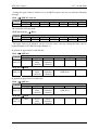
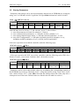
The Manufacturer Status Register (Object Dictionary index 0x1002), a 32-bit object, providing 4 bits per ADC of status information per ADC. The layout of this Register is as follows:
Bits
ADC
31-28
#7
27-24
#6
23-20
#5
19-16
#4
15-12
#3
11-8
#2
7-4
#1
3-0
#0
The individual ADC status bits have the following meaning:
Bit 3
(not used)
Bit 2
Calibration error:
- error during calibration procedure
Bit 1
Conversion error:
- timeout waiting for
conversion-ready
Bit 0
Reset error:
- reset bit not set
and/or
- error in default register contents
Statuses for other ADCs (if more than 8 are present) can be found in OD index 0x2E00.
An ADC status of 0xf (all 4 bits are 1's) denotes that the ADC is not present in the configuration setting (OD index 0x2F00 'Number of ADCs').
16
v2.1 14-Jan-2000
SPICAN CANopen
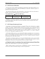
Standardised Device Profile Area (SPICAN)
Index
(hex)
Sub
Index
Name
Data/
Object
Read analogue input
Manufacturer-specific
Number of entries
Record
U8
RO
192
1
2
…
192
252
Input 1
Input 2
…
Input 192
Multiplexor number
I24
I24
…
I24
U8
RO
RO
…
RO
RO
1
253
Input via multiplexor
I24
RO
Interrupt Trigger Selection
Array
Number of analog inputs
U8
RO
192
Input 1
…
Input 64
Input 65
…
Input 192
U8
…
U8
U8
…
U8
RO
…
RO
RO
…
RO
1
…
1
0
…
0
Interrupt source
Array
0
1
…
6
Number of bit banks
Interrupt Source Bank 1
…
Interrupt Source Bank 6
U8
U32
…
U32
RO
RO
…
RO
6
Determines which channel has
produced interrupts: which
channel has exceeded upper limit
Space for 192 input channels
Bitmask for chan 1-32
…
Bitmask for chan 160-192
-
Global Interrupt Enable
Bool
RW
TRUE
Interrupt => PDO1 transmission
Array
0
1
Input Interrupt Upper
Limit
Number of analogue inputs
Upper limit input 1
U8
U32
RO
RW
192
32767
…
192
255
…
Upper limit input 192
Set upper limit all channels
…
U32
U32
…
RW
WO
…
32767
6404
0
6421
0
1
…
64
65
…
192
6422
6423
6424
Attr
Default
(hex)
Comment
Here: 8 bits status, 16 bits analogue value
Fixed, but actual hardware configuration may vary
1st analog input (24-bit)
2nd "
"
"
…
192th "
"
"
Defines which mux in the OD is
used (DSP-404); but in this profile we don't define the mux itself
Read input #<mux1> (DSP-404)
Reference to ways in which interrupts may be triggered: here
available for completeness only
Upper limit interrupt supported
on all input channels in principle
Bit 0: upper limit exceeded
"
"
"
"
"
"
"
"
"
"
"
"
"
"
"
(Default = max. ADC value =>
no interrupt generated)
…
"
"
"
Convenient entry for setting one
limit for all channels
Table 3. Standardised Device Profile Area of the CANopen Object Dictionary for a device with CS5525
ADCs (providing 192 input channels, sufficient for six 32-channel ADCs, twelve 16-channel
ADCs or twenty-four 8-channel ADCs).
17
v2.1 14-Jan-2000
SPICAN CANopen
Manufacturer-specific Profile Area (SPICAN)
Index
(hex)
Sub
Index
2A00
0
1
2
3
4
5
6
7
8
2A01
…
2A17
2B00
0
1
2
3
4
5
6
7
2B01
…
2B17
Name
Data/
Object
ADC-configuration 1
ADC#0
Number of entries
Number of input channels
Conversion Word Rate
Input Voltage Range
Unipolar/Bipolar
Measurement Mode
Power Save Mode
Offset Register
Gain Register
D3-D0 pins
ADC-configuration
ADC#1
…
ADC-configuration
ADC#23
Record
ADC-calibrationconfiguration ADC#0
Number of entries
Conversion word rate during calibration
Offset calibration type
Offset calib input channel
Gain calibration type
Gain calib input channel
Offset value
Gain value
ADC-calibrationconfiguration ADC#1
…
ADC-calibrationconfiguration ADC#23
Attr
U8
U8
U8
U8
U8
RO
RW
RW
RW
RW
U8
U32
U32
U8
Record
WO
RW
RW
RW
Default
(hex)
8
32
0
0
0
Comment
[0,32] and <= OD 0x2F10
3-bit code 2
3-bit code 3
0 = bipolar, 1 = unipolar
1 = power save
CS5525 Offset Register
CS5525 Gain Register
part of CS5525 Config Register
…
Record
Max. 24 ADCs allowed
Record
U8
U8
RO
RO
7
0
U8
U8
U8
U8
U32
U32
Record
RW
RW
RW
RW
RO
RO
5
31
6
30
3-bit code 2
(always set to 15.02 Hz)
3-bit code 4
[0,31] and < OD-index 0x2F10
3-bit code 4
[0,31] and < OD-index 0x2F10
24-bits significant
24-bits significant
…
Record
Max. 24 ADCs allowed
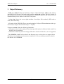
Table 4. Manufacturer-specific Profile Area of the CANopen Object Dictionary for a device with CS5525ADCs.
1
write access allowed only when ADC-input scanning not active (2nd-transmit-PDO inhibit time = 0)
2
000: 15.02 Hz,
100: 168.9 Hz,
001: 30.06 Hz, 010: 60.01 Hz,
101: 202.27 Hz, 110: 3.76 Hz,
011: 123.18 Hz,
111: 7.51 Hz
3
000: 100 mV,
001: 55 mV,
011: 1 V,
4
001: offset self-calibration,
101: offset system-calibration,
010: 25 mV,
010: gain self-calibration,
110: gain system-calibration
18
100: 5 V
v2.1 14-Jan-2000
SPICAN CANopen
Manufacturer-specific Profile Area (SPICAN) (continued…)
Index
(hex)
Sub
Index
Name
Data/
Object
Attr
2C00
2D00
-
ADC-reset-and-calibrate 5
U8
WO
n
Reset ADC#n (0<=n<=23) and
perform a calibration sequence
-
ADC-reset 5
U8
WO
n
Reset ADC#n (0<=n<=23)
0
1
ADC status
Number of status words
status ADC #0-#7
Array
U8
U32
RO
RO
3
2
3
status ADC #8-#15
status ADC #16-#23
U32
U32
RO
RO
Space for 24 ADCs (4 bits/ADC)
(= Object 0x1002)
ADC error/time-out, etc.
ADC error/time-out, etc.
"
"
2F00
-
Number of ADCs
U8
RW
6
To be set to highest number of
ADC connected
NB: (OD-index 2F00) * (ODindex 2F10) <=192
2F10
-
Reserved number of channels per ADC
U8
RW
32
One number for all ADCs;
determines channel numbering
scheme;
can be set to 8, 16 or 32 only;
actual number of channels in use
to be set for each ADC individually in entry 0x2Axx, sub 1.
2E00
Default
(hex)
Comment
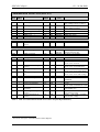
Table 5. Manufacturer-specific Profile Area of the CANopen Object Dictionary for a device with CS5525ADCs (continued).
5
write access allowed only when ADC-input scanning not active (2nd-transmit-PDO inhibit time = 0)
19
v2.1 14-Jan-2000
SPICAN CANopen
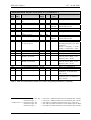
References
[1] 20CN592 80C592 based micro module with on board CAN bus controller,
User's Manual Rev1.3, Micro-key B.V., 1996.
[2] CS5525/CS5526 16-bit / 20-bit multi-range ADC with 4-bit latch,
data sheet, Crystal Semiconductor Corporation, Sep 1996.
[3] CAN-in-Automation,
CANopen, CAL-based Communication Profile for Industrial Systems,
CiA DS-301, Version 3.0, Oct 1996.
[4] CAN-in-Automation,
CANopen Device Profile for I/O Modules,
CiA DSP-401, Version 1.4, Dec 1996.
[5] CAN-in-Automation,
CANopen Device Profile for Measuring Devices and Closed-Loop Controllers,
CiA DSP-404, Revision 1.13, Nov 2 1998.
[6] H.Boterenbrood,
CANopen, high-level protocol for CAN-bus,
Version 2.0a, NIKHEF, Amsterdam, April 7 1999.
(http://www.nikhef.nl/pub/departments/ct/po/doc/CANopen20.pdf).
20
v2.1 14-Jan-2000
SPICAN CANopen
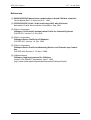
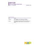
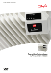
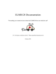
APPENDIX A LEDs, Switches and Jumpers
SPICAN Frontpanel:
Red LED:
CAN-controller error:
bus errors, buffer overflow
(message(s) lost!)
SPICAN
CAN
Green LED:
CAN-bus activity
(receiving/sending)
Green LEDs 'CAN'' and 'SYS':
+5V power-supply indications for
CAN-bus driver and other onboard
electronics resp.
+5V
CAN
SYS
Red LED:
error occurred on an ADC
(check for received Emergency Objects
and/or ADC statuses)
I/O
Node-ID
Node-ID and CAN baudrate setting:
0x01-0x7F: Node-ID 1 to 127, 125 kbit/s
0x81-0xFF: Node-ID 1 to 127, 250 kbit/s
(top switch: high nibble,
bottom switch: low nibble)
Green LED:
I/O activity, e.g. ADC conversion read-out
o
Hole for access to reset button
CAN-bus connector
CAN
RS232 connector; 4800 baud (8-N-1),
for code download and
display of (debug) information by node
RS232
SN: 1
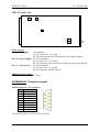
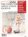
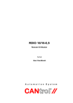
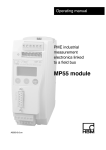
SPICAN component side:
backplane connector
: J5
::
1
J4 J3 :: J1
3
Micro-key
20CN592
microcontroller
module
:
:
J6
space for DC-DC
convertor
space for fuse
J7
NB: wire-bridges in place as shown,
in case of local power-supply
J1:
J3:
J4:
80C592 internal watchdog (J1/1-2 closed: disabled; J1/2-3 closed: enabled).
powerfail interrupt request via P1.0/#INT2 pin (open: interrupt disabled)
external watchdog enable selector, 80C592 pin P1.1 to MAX691 (open watchdog disabled).
J5:
reset jumper (closed: system will reset).
J6/J7: serial port signal connection/disconnection.
21
v2.1 14-Jan-2000
SPICAN CANopen
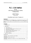
SPICAN solder side:
.J8.
J9
..
J13
..
J10
J11
Power options:
Local power supply:
..
..
via backplane
J8 + J9 closed, J10 + J11 open,
DC-DC convertor and fuse NOT placed, wire-bridges in place.
Ext. +5V power supply: via CAN-connector
J8 + J9 open, J10 + J11 closed,
DC-DC convertor NOT placed (wire-bridges in place), fuse placed.
Ext. +9…36V power-s.: via CAN-connector
J8 + J9 open, J10 + J11 closed,
DC-DC convertor and fuse placed.
Additional power option:
Battery backup:
J13 open.
APPENDIX B Connector Layout
9-pin D-sub male CAN-connector:
Pin
Signal
1
–
2
CAN_Low
3
V_gnd
4
–
5
–
6
–
7
CAN_High
8
–
9
V+
*(backpanel connector layout to be provided)*
22