1
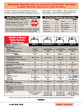
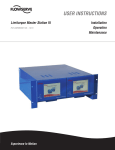
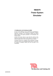
OPERATING AND SERVICE MANUAL
Universal Interface
Device 46
MAGNA-POWER ELECTRONICS, INC.
39 ROYAL ROAD, FLEMINGTON, NJ 08822
September 5, 2009
SAFETY NOTICE
Universal Interface Device 46 (UID46) connects two or more power supplies for master/slave
configurations or for other user configured applications. Before applying power to the system,
verify that the system is configured properly for the specific application and that ratings are not
exceeded on any input or output terminal.
Installation and service must be performed only by properly trained and qualified personnel who
are aware of dealing with electrical hazards. Ensure that the ac power line ground is properly
connected to the power supply chassis. Furthermore, other power grounds, including those
connected to application maintenance equipment, must be grounded for both personnel and
equipment safety.
Always ensure that facility ac input power is de-energized prior to connecting or disconnecting
the input and output power cables.
Caution: While the UID46 is a low voltage device, lethal voltages may be
present inside the connecting power supply even when the ac input voltage is
disconnected. Only properly trained and qualified personnel should remove
covers and access the inside of the power supply.
During normal operation, the operator does not have access to hazardous voltages within the
cabinet. Depending on the user’s application, high voltages hazardous to human safety may be
generated normally on the output terminals of the connecting power supply. Ensure that the
output power cables are properly labeled as to the safety hazards and that any inadvertent contact
with hazardous voltages is eliminated.
The connecting power supply is designed to be permanently connected to the power source
requiring a readily accessible disconnect device incorporated in the fixed wiring.
These operating instructions form an integral part of the equipment and must be available to the
operating personnel at all times. All the safety instructions and advice notes are to be followed.
Neither Magna-Power Electronics, Inc. nor any of the associated sales organizations can accept
responsibility for personal injury, consequential injury, loss, or damage that results from
improper use of the equipment and accessories.
i
LIMITED WARRANTY
The following is made in lieu of all warranties expressed or implied.
Magna-Power Electronics, Inc. warranties its products to be free of manufacturing defects for a
period of two (2) years from date of original shipment from its factory. Magna-Power
Electronics, Inc. will repair, replace, or refund the purchase price at its discretion, which upon
examination by Magna-Power Electronics, Inc., is determined to be defective in material or
workmanship, providing such claimed defective material is returned upon written authorization
of Magna-Power Electronics, Inc., freight prepaid.
For products failing within the first 30 days of the warranty period, Magna-Power Electronics,
Inc. will return the repaired product at its expense using a standard shipping method; after 30
days of the warranty period, the repaired product will be returned at the customer’s expense using
the customer’s requested shipping method.
Damage due to corrosion, customer alterations, excessive dust, extreme environmental or
electrical conditions, and/or misuse will be evaluated upon inspection. If inspection reveals that
the cause of damage is not due to materials or workmanship, repair of the product will be treated
on a non-warranty basis.
All electrical, commercial supply parts, and items not manufactured by Magna-Power
Electronics, Inc. shall carry the warranty of the original manufacturer and no more, but under no
circumstances to exceed the warranty period. Replacement parts shall be warranted for a period
of 90 days.
Warranty labor shall only apply if the product, assembly, or part is returned to the factory freight
prepaid and insured. Damage or breakage while in transit is not covered by this warranty.
Magna-Power Electronics, Inc. assumes no responsibility to Buyer for labor to diagnose and
remove defective product and installation of replacement product. Furthermore, Magna-Power
Electronics, Inc. is not liable to Buyer or to any third party for consequential or incidental
damages under any circumstances, whether due to defect in the product, due to delay or failure of
delivery, due to a failure of the product to perform as specified, or for any other reason or cause.
Buyer and Magna-Power Electronics, Inc. agree that Buyer’s sole remedy and Magna-Power
Electronics, Inc.’s sole liability to Buyer is limited to repair, replacement, or refund of the
purchase price of the product as described herein, whether Buyer’s claim arises out of contract or
in tort.
All claims against the warranty shall be the final determination of Magna-Power Electronics, Inc.
ii
CLAIM FOR DAMAGE IN SHIPMENT
This instrument received comprehensive mechanical and electrical inspections before shipment.
Immediately upon receipt from the carrier, and before operation, this instrument should be
inspected visually for damage caused in shipment. If such inspection reveals internal or external
damage in any way, a claim should be filed with the carrier. A full report of the damage should
be obtained by the claim agent and this report should be forwarded to us. We will then advise
you of the disposition to be made of the equipment and arrange for repair or replacement. When
referring to this equipment, always include the model and serial number.
RETURNING EQUIPMENT
Before returning any equipment to the factory, the following steps should be taken:
1.
Contact our technical service department. Give a full description of the difficulty and
include the model and serial number of the unit. On receipt of this information, we will
give you service information or shipping instructions.
2.
Packaging and method of shipment must be coordinated with the factory to insure safe
delivery. All equipment returned for repair require a Return Authorization Number and
must be insured. No returns will be accepted without assignment of a Return
Authorization Number.
3.
For non-warranty repairs, we will submit a cost estimate for your approval before
proceeding.
iii
TABLE OF CONTENTS
Section
Title
Page
1.0 GENERAL INFORMATION
1.1
Description
1.2
Features
1.3
IEC Symbols Used in Manual
1.4
Power Requirements
1.5
Specifications
1
1
1
1
1
1
2.0 INSTALLATION AND OPERATION
2.1
General
2.2
Master/Slave Parallel Operation
2.3
Master/Slave Series Operation
2.4
Custom Configurations
4
4
4
7
8
iv
1.0 GENERAL INFORMATION
1.1
Description
This manual contains operation and maintenance instructions for Magna-Power Electronics'
Universal Interface Device 46 (UID46). The UID46 allows users to connect power supplies for
master/slave parallel or series operation or allows connections to external control circuitry with
easy access screw terminals.
1.2
Features
The UID46 is a general purpose device for connection to Magna-Power Electronics’ XR, TSiii,
MSiii, and MTiv Series power supplies. The device contains the necessary circuitry for
configuring power supplies for master/slave parallel or series operation. Master/slave parallel
operation allows two or more power supplies to equally share output current when connected
together. Master/slave series operation allows two or more power supplies to equally share
output voltage when connected together.
The UID46 can be used as an interface for connecting control and monitoring lines to external
circuitry. It also contains an area on the printed circuit board for interconnecting wires and
placing components for specific user applications.
1.3
IEC Symbols Used in Manual
The following IEC symbols are used in this manual.
Caution, risk of electric shock
Caution, risk of danger
Protective conductor terminal
Three-phase alternating current
1.4
Power Requirements
None
1.5
Specifications
1
The following specifications describe the published operational characteristics of the UID46.
UID46 connectors, see figure 1.1 for details:
JR1,2,3: 37 pin D-subminature, female
JR4: 10 pin plug connector
Size: 1.210"H x 7.140"W x 4.010"D, see figure 1.2 for details.
Weight: 6.54 oz.
Figure 1.1 UID46 connectors (a) JR1,2,3 and ( b) JS4
(viewed from UID46)
2
Figure 1.2 UID46 Enclosure
3
2.0 INSTALLATION AND OPERATION
2.1
General
The UID46 is a general purpose device for connection between Magna-Power Electronics’ XR,
TSiii, MSiii, and MTiv Series power supplies and user devices.
Figure 2.1 shows the electrical circuit of the UID46 and figure 2.2 shows jumpers connections for
master/slave parallel and series operation. The following sections describe how to use the device
for master/slave parallel and series operation and for custom applications.
Caution: As shipped, the UID46 is configured for master/slave parallel
operation.
2.2
Master/Slave Parallel Operation
Two or more Magna-Power Electronics’ power supplies can be connected in parallel to obtain a
total output current greater than that available from one power supply. The total output current is
the sum of the output currents of the individual power supplies. Each power supply can be turned
on or off separately.
Master/slave parallel operation permits equal current sharing under all load conditions and allows
complete control of output current from one master power supply.
To configure the power supplies for master/slave parallel operation, disconnect power to the
power supplies and connect all units and loads in parallel as shown in Figure 2.3. Remove the
cover of the UID46 and set the jumpers settings according to Figure 2.2 for master/slave parallel
configuration. This is the factory default setting. Replace the cover and connect a 37-conductor
male to male cable from connector JS1 of the master power supply to connector JR2 of the
UID46. Connect a second 37-conductor male to male cable from connector JS1 of the slave
power supply to connector JR1 of the UID46.
The jumper settings perform the following functions:
1.
Jumper connection between terminals 19,20 connects the current monitoring
voltage, IO2, on the master power supply to the external current set point input on
the slave power supply. This makes the slave power supply operate at the same
current output as the master power supply
2.
Jumper connection between terminals 11,12 connects the power output digital
control line of the master power supply to the start digital control line of the slave
power supply. This connection causes the slave unit to turn on when the master
unit is turned on.
4
Figure 2.1 Schematic of UID46
(a)
(b)
Figure 2.2 Jumper JP1 settings for (a) master/slave parallel and (b) master/slave series
5
3.
4.
Jumper connection between terminals 13,14 connects the standby/alm digital
control line of the master power supply to the stop digital control line of the slave
power supply. This connection causes the slave unit to turn off when the master
unit is turned off or when a diagnostic condition appears.
Jumper connections between terminals 3,4; 5,6; 7,8; 9,10; 15,16 set the slave
voltage set point to maximum and the voltage trip and over current trip set points
just beyond full scale values.
The slave power supply must be configured for external program input. The master unit can be
configured for rotary, keypad, external program, or remote input. Refer to the power supply
manual for setting the configuration commands.
Three or more parallel connected power supplies can be interconnected by applying additional
UID46 units; one UID46 is required for every slave power supply. As illustrated in figure 2.3 for
two slave power supplies, follow the previous instructions plus connect an additional 37conductor male to male cable from JS1 of the second slave power supply to JR1 of the second
UID46. Connect a 37-conductor male to male cable between connector JR3 and JR2 of the two
UID46 units. Interconnecting UID46 units routes master control and monitoring signals to all of
the slave power supplies.
Figure 2.3 Master/slave parallel connection for (a) one or (b) more slave power supplies
6
2.3
Master/Slave Series Operation
Two or more power supplies can be connected in series to obtain a total output voltage greater
than that available from one power supply. The total output voltage is the sum of the output
voltage of the individual power supplies. Each power supply can be turned on or off separately.
Caution: No plus or minus voltage should exceed 1000 Vdc with respect to
ground for models rated 1000 V less. No plus or minus voltage should exceed
4000 Vdc with respect to ground for models rated greater than 1000 V.
Master/slave series operation permits equal voltage sharing under all load conditions and allows
complete control of output voltage from one master power supply.
To configure the power supplies for master/slave series operation, disconnect power to the power
supplies and connect all units and loads in series as shown in Figure 2.4. Remove the cover of the
UID46 and set the jumpers settings according to Figure 2.2 for master/slave series configuration.
Replace the cover and connect a 37-conductor male to male cable from connector JS1 of the
master power supply to connector JR2 of the UID46. Connect a second 37-conductor male to
male cable from connector JS1 of the slave power supply to connector JR1 of the UID46.
The jumper settings perform the following functions:
1.
Jumper connection between terminals 17,18 connects the voltage monitoring
voltage, VO2, on the master power supply to the external voltage set point input on
the slave power supply. This makes the slave power supply operate at the same
voltage output as the master power supply
2.
Jumper connection between terminals 11,12 connects the power output digital
control line of the master power supply to the start digital control line of the slave
power supply. This connection causes the slave unit to turn on when the master
unit is turned on.
3.
Jumper connection between terminals 13,14 connects the standby/alm digital
control line of the master power supply to the stop digital control line of the slave
power supply. This connection causes the slave unit to turn off when the master
unit is turned off or when a diagnostic condition appears.
4.
Jumper connections between terminals 1,2; 3,4; 5,6; 7,8; 15,16 set the slave current
set point to maximum and the voltage trip and over current trip set points just
beyond full scale values.
The slave power supply must be configured for external program input. The master unit can be
configured for rotary, keypad, external program, or remote input. Refer to the power supply
7
manual for setting the configuration commands.
Three or more series connected power supplies can be interconnected by applying additional
UID46 units; one UID46 is required for every slave power supply. As illustrated in figure 2.4 for
two slave power supplies, follow the previous instructions plus connect an additional 37conductor male to male cable from JS1 of the second slave power supply to JR1 of the second
UID46. Connect a 37-conductor male to male cable between connector JR3 and JR2 of the two
UID46 units. Interconnecting UID46 units routes master control and monitoring signals to all of
the slave power supplies.
Figure 2.4 Master/slave series connection for (a) one or (b) more slave power supplies
2.4
Custom Configurations
The UID46 permits users to design and implement their own control circuitry to control or
monitor the power supply’s inputs or outputs. As shown in figure 2.5, the UID46 has a general
purpose area on its printed circuit board to configure custom circuitry or to provide
interconnections to utilize connector JR4. Table 2.1 shows the interface of master and slave
connectors JR1 through JR3 with corresponding pad areas of JX1 and JX2. Connectors JR2 and
JR3 are interconnected to allow daisy chain connections for multiple UID46 units.
JR4 is a 10 terminal connector that mates to a screw terminal plug. This connector is user defined
and can be utilized to externally monitor or control power supply functions. Table 2.2 shows the
interface of connector JR4 and the corresponding pad area. For example, connecting a wire from
terminal 1 of JX3 (USER1) to terminal 15 of JX1 provides a signal to indicate the master power
8
supply is operational.
The multipurpose area in the center of the PCB enables the user to add circuitry within the UID46.
The multipurpose area provides sufficient space to add components like or’ing diodes for
simultaneously monitoring two diagnostic signals. One example is to connect the anodes of two
diodes to the OCT and OVT alarm signal and interconnect the cathodes. This provides a
diagnostic signal on either the OCT or OVT alarm signal.
Table 2.1
JR1
JR2
JR3
1
2
3
4
5
6
7
8
9
10
11
12
13
14
15
16
17
18
19
CONNECTION INTERFACE DESCRIPTION FOR JR1, JR2, AND JR3
JX1
JX2 Description
1
3
5
7
9
11
13
15
17
19
21
23
25
27
29
31
33
35
37
REF GND
REF GND
VREF EXT
TVREF EXT
VO2
+2.5V REF CAL
GND
POWER
THERMAL
INTERLOCK
CUR CTL
STANDBY/ALM
ALM
EXT CTL
FUSE
RESERVE
START
CLEAR
STOP
JR1
JR2
JR3
JX1
JX2 Description
20
21
22
23
24
25
26
27
28
29
30
31
32
33
34
35
36
37
2
4
6
8
10
12
14
16
18
20
22
24
26
28
30
32
34
36
9
REF GND
+10V REF
IREF EXT
TIREF EXT
IO2
VMOD
+5V
PGM LINE
STANDBY
PHASE LOSS
VOLT CTL
RESERVE
OCT
INT CTL
OVT
RESERVE
ARM
INTERLOCK SET
Table 2.2
JR4
1
2
3
4
5
6
7
8
9
10
CONNECTION INTERFACE DESCRIPTION FOR JR4
JX3 Description
1
2
3
4
5
6
7
8
9
10
USER1
USER2
USER3
USER4
USER5
USER6
USER7
USER8
USER9
USER10
Figure 2.5 Printed circuit board layout of the UID46
10