1
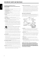
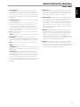
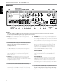
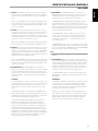
NEDERLANDS
Owner’s Manual
SVENSKA
DEUTSCH
ITALIANO
ESPAÑOL
FRANÇAIS
Stereo Integrated Amplifier
ENGLISH
C 375BEE
РУССКИЙ
®
IMPORTANT SAFETY INSTRUCTIONS
ENGLISH
Save these instructions for later use.
Follow all warnings and instructions marked on the
audio equipment.
FRANÇAIS
ESPAÑOL
ITALIANO
DEUTSCH
NEDERLANDS
SVENSKA
1Read instructions - All the safety and operating instructions should be
read before the product is operated.
2Retain instructions - The safety and operating instructions should be
retained for future reference.
3Heed Warnings - All warnings on the product and in the operating
instructions should be adhered to.
4Follow Instructions - All operating and use instructions should be
followed.
5Cleaning - Unplug this product from the wall outlet before cleaning.
Do not use liquid cleaners or aerosol cleaners. Use a damp cloth for
cleaning.
6Attachments - Do not use attachments not recommended by the
product manufacturer as they may cause hazards.
7Water and Moisture - Do not use this product near water-for example,
near a bath tub, wash bowl, kitchen sink, or laundry tub; in a wet
basement; or near a swimming pool; and the like.
8Accessories - Do not place this product on an unstable cart, stand,
tripod, bracket, or table. The product may fall, causing serious injury to
a child or adult, and serious damage to the product. Use only with a
cart, stand, tripod, bracket, or table recommended by the manufacturer,
or sold with the product. Any mounting of the product should follow
the manufacturer’s instructions, and should use a mounting accessory
recommended by the manufacturer.
9
A product and cart combination should be moved with
care. Quick stops, excessive force, and uneven surfaces may
cause the product and cart combination to overturn.
10Ventilation - Slots and openings in the cabinet are provided for
ventilation and to ensure reliable operation of the product and to
protect it from overheating, and these openings must not be blocked
or covered. The openings should never be blocked by placing the
product on a bed, sofa, rug, or other similar surface. This product should
not be placed in a built-in installation such as a bookcase or rack unless
proper ventilation is provided or the manufacturer’s instructions have
been adhered to.
11Power Sources - This product should be operated only from the type
of power source indicated on the marking label. If you are not sure of
the type of power supply to your home, consult your product dealer or
local power company.
The primary method of isolating the amplifier from the mains supply
is to disconnect the mains plug. Ensure that the mains plug remains
accessible at all times. Unplug the AC power cord from the AC outlet if
the unit will not be used for several months or more.
12Grounding or Polarization - This product may be equipped with a
polarized alternating-current line plug (a plug having one blade wider
than the other). This plug will fit into the power outlet only one way.
This is a safety feature. If you are unable to insert the plug fully into the
outlet, try reversing the plug. If the plug should still fail to fit, contact
your electrician to replace your obsolete outlet. Do not defeat the safety
purpose of the polarized plug.
13Power - Cord Protection - Power-supply cords should be routed so that
they are not likely to be walked on or pinched by items placed upon or
against them, paying particular attention to cords at plugs, convenience
receptacles, and the point where they exit from the product.
РУССКИЙ
14Outdoor Antenna Grounding - If an outside antenna or cable system
is connected to the product, be sure the antenna or cable system is
grounded so as to provide some protection against voltage surges
and built-up static charges. Article 810 of the National Electrical Code,
ANSI/NFPA 70, provides information with regard to proper grounding
of the mast and supporting structure, grounding of the lead-in wire
to an antenna discharge unit, size of grounding conductors, location
of antenna discharge unit, connection to grounding electrodes, and
requirements for the grounding electrode.
NOTE TO CATV SYSTEM INSTALLER
This reminder is provided to call the CATV system installer’s attention to Section
820-40 of the NEC which provides guidelines for proper grounding and, in
particular, specifies that the cable ground shall be connected to the grounding
system of the building, as close to the point of cable entry as practical.
15Lightning - For added protection for this product during a lightning
storm, or when it is left unattended and unused for long periods of
time, unplug it from the wall outlet and disconnect the antenna or
cable system. This will prevent damage to the product due to lightning
and power-line surges.
16Power Lines - An outside antenna system should not be located in the
vicinity of overhead power lines or other electric light or power circuits,
or where it can fall into such power lines or circuits. When installing an
outside antenna system, extreme care should be taken to keep from
touching such power lines or circuits as contact with them might be
fatal.
17Overloading - Do not overload wall outlets, extension cords, or
integral convenience receptacles as this can result in a risk of fire or
electric shock.
18Object and Liquid Entry - Never push objects of any kind into this
product through openings as they may touch dangerous voltage points
or short-out parts that could result in a fire or electric shock. Never spill
liquid of any kind on the product.
WARNING: The apparatus should noT be exposed to
dripping or splashing, and objects filled with liquids,
such as vases, should not be placed on the apparatus.
As with any electronic products, use care not to spill
liquids into any part of the system. Liquids can cause a
failure and/or a fire hazard.
This equipment generates, uses and can radiate radio frequency energy and if
not installed and used in accordance with the instructions, may cause harmful
interference to radio communications. However, there is no guarantee that
interference will not occur in a particular installation. If this equipment does
cause harmful interference to radio or television reception, which can be
determined by turning the equipment off and on, the user is encouraged to try
to correct the interference by one or more of the following measures
• Reorient or relocate the receiving antenna.
• Increase the separation between the equipment and receiver.
• Connect the equipment into an outlet on a circuit different from
that to which the receiver is connected
• Consult the dealer or an experienced radio/TV technician for help.
FRANÇAIS
ITALIANO
ESPAÑOL
THE EXCLAMATION POINT WITHIN AN EQUILATERAL TRIANGLE IS
INTENDED TO ALERT THE USER TO THE PRESENCE OF IMPORTANT
OPERATING AND MAINTENANCE (SERVICING) INSTRUCTIONS IN
THE LITERATURE ACCOMPANYING THE APPLIANCE.
The equipment draws its nominal non-operational power from the AC
outlet with its POWER switch in the STANDBY position.
The socket-outlet shall be installed near the apparatus and shall be easily
accessible.
DEUTSCH
FCC NOTICE
This equipment has been tested and found to comply with the limits for a
Class B digital device, pursuant to part 15 of the FCC Rules. These limits are
designed to provide reasonable protection against harmful interference in a
residential installation.
THE LIGHTNING FLASH WITH ARROWHEAD SYMBOL, WITHIN
AN EQUILATERAL TRIANGLE, IS INTENDED TO ALERT THE USER
TO THE PRESENCE OF UNINSULATED “DANGEROUS VOLTAGE”
WITHIN THE PRODUCT’S ENCLOSURE THAT MAYBE OF
SUFFICIENT MAGNITUDE TO CONSTITUTE A RISK OF ELECTRIC
SHOCK TO PERSONS.
CAUTION
Changes or modifications to this equipment not expressly approved by
NAD Electronics for compliance could void the user’s authority to operate
this equipment.
CAUTION REGARDING PLACEMENT
To maintain proper ventilation, be sure to leave a space around the unit
(from the largest outer dimensions including projections) that is equal to or
greater than shown below.
Left and Right Panels: 10 cm
Rear Panel: 10 cm
Top Panel: 50 cm
NEDERLANDS
CAUTION
TO PREVENT ELECTRIC SHOCK, MATCH WIDE BLADE OF PLUG TO WIDE SLOT,
FULLY INSERT.
INDUSTRY CANADA REQUIREMENT
This Class B digital apparatus meets all requirements of the Canadian
Interference-Causing Equipment Regulations.
SVENSKA
WARNING
TO REDUCE THE RISK OF FIRE OR ELECTRIC SHOCK, DO NOT EXPOSE THIS
PRODUCT TO RAIN OR MOISTURE.
FCC WARNING
Changes or modifications not expressly approved by the party responsible
for compliance could void the user’s authority to operate the equipment.
РУССКИЙ
19Damage Requiring Service - Unplug this product from the wall outlet
and refer servicing to qualified service personnel under the following
conditions:
a) When the power-supply cord or plug is damaged.
b) If liquid has been spilled, or objects have fallen into the product.
c) If the product has been exposed to rain or water.
d) If the product does not operate normally by following the operating
instructions. Adjust only those controls that are covered by the
operating instructions as an improper adjustment of other controls
may result in damage and will often require extensive work by a
qualified technician to restore the product to its normal operation.
e) If the product has been dropped or damaged in any way.
f) when the product exhibits a distinct change in performance-this
indicates a need for service.
20Replacement Parts - When replacement parts are required, be
sure the service technician has used replacement parts specified
by the manufacturer or have the same characteristics as the
original part. Unauthorized substitutions may result in fire, electric
shock, or other hazards.
21 Safety Check - Upon completion of any service or repairs to this
product, ask the service technician to perform safety checks to
determine that the product is in proper operating condition.
22Wall or Ceiling Mounting - The product should be mounted to a wall
or ceiling only as recommended by the manufacturer.
23Heat - The product should be situated away from heat sources such as
radiators, heat registers, stoves or other products (including amplifiers)
that produce heat.
ENGLISH
IMPORTANT SAFETY INSTRUCTIONS
IMPORTANT SAFETY INSTRUCTIONS
ENGLISH
FRANÇAIS
IMPORTANT INFORMATION FOR UK CUSTOMERS
DO NOT cut off the mains plug from this equipment. If the plug fitted is not
suitable for the power points in your home or the cable is too short to reach
a power point, then obtain an appropriate safety approved extension lead
or consult your dealer. If, nonetheless, the mains plug is cut off, REMOVE
THE FUSE and dispose of the PLUG immediately, to avoid possible shock
hazard by inadvertent connection to the mains supply. If this product is
not provided with a mains plug, or one has to be fitted, then follow the
instructions given below:
IMPORTANT
DO NOT make any connection to the larger terminal which is marked with
the letter ‘E’ or by the safety earth symbol or colored GREEN or GREEN AND
YELLOW.
ESPAÑOL
The wires in the mains lead on this product are colored in accordance with
the following code:
BLUE – NEUTRAL
BROWN – LIVE
ITALIANO
As these colors may not correspond with the colored markings identifying
the terminals in your plug, proceed as follows:
The BLUE wire must be connected to the terminal marked with the
letter ‘N’ or colored BLACK.
The BROWN wire must be connected to the terminal marked with the
letter ‘L’ or colored RED.
When replacing the fuse, only a correctly rated and approved type should
be used, and be sure to re-fit the fuse cover.
IF IN DOUBT CONSULT A COMPETENT ELECTRICIAN.
DEUTSCH
NOTES ON ENVIRONMENTAL PROTECTION
At the end of its useful life, this product must not be disposed
of with regular household waste but must be returned to a
collection point for the recycling of electrical and electronic
equipment. The symbol on the product, user’s manual and
packaging, point this out.
INFORMATION ABOUT COLLECTION AND DISPOSAL OF
WASTE BATTERIES (DIRECTIVE 2006/66/EC OF THE EUROPEAN
PARLIAMENT AND THE COUNCIL OF EUROPEAN UNION) (for
European customers only)
Batteries bearing any of these symbols indicate
that they should be treated as “separate collection”
and not as municipal waste. It is encouraged that
necessary measures are implemented to maximize
the separate collection of waste batteries and
to minimize the disposal of batteries as mixed
municipal waste.
End-users are exhorted not to dispose waste
batteries as unsorted municipal waste. In order
to achieve a high level of recycling waste batteries, discard waste batteries
separately and properly through an accessible collection point in your
vicinity. For more information about collection and recycling of waste
batteries, please contact your local municipality, your waste disposal service
or the point of sale where you purchased the items.
By ensuring compliance and conformance to proper disposal of waste
batteries, potential hazardous effects on human health is prevented and
the negative impact of batteries and waste batteries on the environment
is minimized, thus contributing to the protection, preservation and quality
improvement of the environment.
NOTE: The C 375BEE is not an auto voltage UNIT. Connect
only to the prescribed AC outlet, i.e., 120V 60Hz or 230V 50Hz.
RECORD YOUR MODEL NUMBER (NOW, WHILE YOU CAN SEE IT)
The model and serial number of your new C 375BEE are located on the
back of the cabinet. For your future convenience, we suggest that you
record these numbers here:
Model no:. . . . . . . . . . . . . . . . . . . . . . . . . . . . . . . . . . . . . . Serial no.: . . . . . . . . . . . . . . . . . . . . . . . . . . . . . . . . . . . . . .
NEDERLANDS
The materials can be reused in accordance with their markings. Through
re-use, recycling of raw materials or other forms of recycling of old
products, you are making an important contribution to the protection of
our environment. Your local administrative office can advise you of the
responsible waste disposal point.
SVENSKA
РУССКИЙ
NAD is a trademark of NAD Electronics International, a division of Lenbrook Industries Limited
Copyright 2008, NAD Electronics International, a division of Lenbrook Industries Limited
INTRODUCTION
It is especially important that sufficient ventilation be provided. If you are
contemplating locating the C 375BEE within a cabinet or other furniture,
consult your NAD audio/video specialist for advice on providing adequate
airflow.
NOTES ON INSTALLATION
Your NAD C 375BEE should be placed on a firm, level surface. Avoid
placing the unit in direct sunlight or near sources of heat and damp. Allow
adequate ventilation. Do not place the unit on a soft surface like a carpet.
Do not place it in an enclosed position such a bookcase or cabinet that
may impede the air-flow through the ventilation slots. Make sure the unit is
switched off before making any connections.
FRANÇAIS
Bare wires and pin sockets should be inserted into the hole in the shaft
of the terminal. Unscrew the speaker terminal’s plastic bushing until the
hole in the screw shaft is revealed. Insert the pin or bare cable end into
the hole and secure the cable by tightening down the terminal’s bushing.
Ensure bare wire from the speaker cables does not touch the back panel or
another socket. Ensure that there is only 1/2” (1cm) of bare cable or pin and
no loose strands of speakers wire.
QUICK START
In case you simply cannot wait to experience the performance of your new
NAD C 375BEE, we provide the following “QUICK START” instructions to get
you underway.
Please make all the connections to your C 375BEE with the unit unplugged.
It is also advisable to power-down or unplug all associated components
while making or breaking any signal or AC power connections.
1 Connect the speakers to the rear Speaker terminals and sources to the
relevant rear input sockets.
2 Connect the AC cord to the C 375BEE’s AC Mains input and then plug
into an AC outlet.
3 Switch the POWER switch on the rear panel to the “ON” setting in order
to turn the C 375BEE to standby mode. The Standby LED indicator
embedded around the bezel of the STANDBY button will illuminate
amber. The C 375BEE will go to standby mode.
4 Press the STANDBY button to turn ON the C 375BEE. The Standby LED
indicator will turn from amber to blue.
5 Press the required input selector.
ESPAÑOL
CHOOSING A LOCATION
Choose a location that is well ventilated (with at least several inches to
both sides and behind), and that will provide a clear line of sight, within
23 feet/7 meters, between the C 375BEE’s front panel and your primary
listening/viewing position. This will ensure reliable infrared remote control
communications. The C 375BEE generates a modest amount of heat, but
nothing that should trouble adjacent components. It is perfectly possible to
stack the C 375BEE atop other components, but the reverse usually should
be avoided.
WARNING: The terminals marked with this symbol
are hazardous live. External wiring connected to these
terminals requires installation by an instructed person or
the use of ready-made leads or cords.
ITALIANO
SAVE THE PACKAGING
Please save the box and all of the packaging in which your C 375BEE
arrived. Should you move or otherwise need to transport your C 375BEE,
this is by far the safest container in which to do so. We’ve seen too many
otherwise perfect components damaged in transit for lack of a proper
shipping carton, so please: Save that box!
BARE WIRES AND PIN CONNECTORS
DEUTSCH
UNPACKING AND SETUP
WHAT’S IN THE BOX
Packed with your C 375BEE you will find:
• The SR 8 remote control with 2 (two) AA batteries
• This owner’s manual
• A detachable AC power cord.
ENGLISH
GETTING STARTED
NEDERLANDS
The RCA sockets on your NAD C 375BEE are colour coded for convenience.
Red and white are Right and Left audio respectively.
Use high quality leads and sockets for optimum performance and reliability.
Ensure that leads and sockets are not damaged in any way and all sockets
are firmly pushed home.
For best performance, use quality speaker leads of 16 gauge (1.5mm)
thickness or more. If the unit is not going to be used for some time,
disconnect the plug from the AC socket.
SVENSKA
Should water get into your NAD C 375BEE, shut off the power to the unit
and remove the plug from the AC socket. Have the unit inspected by a
qualified service technician before attempting to use it again.
DO NOT REMOVE THE COVER; THERE ARE NO USER-SERVICEABLE
PARTS INSIDE.
РУССКИЙ
Use a dry soft cloth to clean the unit. If necessary, lightly dampen the cloth
with soapy water. Do not use solutions containing benzol or other volatile
agents.
IDENTIFICATION OF CONTROLS
FRONT PANEL
ENGLISH
1
2
3
4
5
6
FRANÇAIS
ESPAÑOL
7
8
9
ITALIANO
1 STANDBY: With the rear panel POWER switch set to ON position,
press this button to switch ON the C 375BEE from standby mode.
The Standby LED indicator will turn from amber to blue. Pressing the
STANDBY button again turns the unit back to standby mode.
The C 375BEE can also be switched ON from standby mode by pressing
any of the front panel buttons.
2 STANDBY LED: This indicator will light up amber when the C 375BEE
is in standby state. When the C 375BEE is at ON state, this indicator will
illuminate blue. When infrared command from the SR 8 is received, this
indicator will also flash momentarily.
DEUTSCH
In cases of serious abuse of the C 375BEE, such as excessively low
loudspeaker impedance and short circuit, the C 375BEE will engage its
Protection circuitry, indicated by the Standby LED turning from blue to
red and the sound being muted.
NEDERLANDS
In such a case, turn the C 375BEE OFF by the rear panel POWER switch,
wait for it to cool down and/or check the speaker connections, making
sure the overall loudspeaker impedance doesn’t go below 4 ohms or
8 ohms in Bridge Mode. Once the cause for the protection circuitry to
engage has been removed, switch ON the rear POWER switch and the
STANDBY button to resume normal operation.
SVENSKA
3BRIDGE MODE INDICATOR: This BRIDGE MODE indicator lights up
blue when the C 375BEE is switched to Bridge Mode. Refer also to the
item below about BRIDGE MODE at the IDENTIFICATION OF CONTROLS
– REAR PANEL.
4MP SOCKET: Using a 3.5mm stereo plug, connect into this socket the
audio output of a Media Player.
РУССКИЙ
NOTES
• If an external Media Player is connected to the front MP socket (using a
3.5mm stereo plug) while listening to a MP line-level source, the external
Media Player will be directly selected with the MP line-level source
immediately disconnected. • It is recommended to mute the volume or switch to a different input
before plugging/unplugging the external Media Player cable.
10
11
12
13
5 SOFT CLIPPING INDICATOR: The blue SOFT CLIPPING LED shows
that the SOFT CLIPPING mode is engaged. Refer also to the item below
about SOFT CLIPPING (item 13) at the IDENTIFICATION OF CONTROLS
– REAR PANEL.
6REMOTE SENSOR: Point the SR 8 remote control at the remote
sensor and press the buttons. Do not expose the remote sensor of the
C 375BEE to a strong light source such as direct sunlight or illumination.
If you do so, you may not be able to operate the C 375BEE with the
remote control.
Distance: About 23ft (7m) from the front of the remote sensor.
Angle: About 30o in each direction of the front of the remote sensor.
7PHONES: A 1/4” stereo jack socket is supplied for headphone listening
and will work with conventional headphones of any impedance. The
headphone socket will work in parallel to the selected speakers. To
listen to headphones only, de-select Speakers A and/or B. The volume,
tone and balance controls are operative for headphone listening. Use
a suitable adapter to connect headphones with other types of sockets,
such as 3.5mm “personal stereo” jack plugs.
NOTE
Make certain that the volume control is turned to minimum (fully
counter-clockwise) before connecting or disconnecting headphones.
Listening at high levels can damage your hearing.
8 SPEAKERS A, B: The SPEAKERS A and B buttons engage or disengage
the speakers connected respectively to the SPEAKERS A and SPEAKERS
B terminals on the rear panel. Press “A” to switch ON or OFF the speakers
connected to the SPEAKERS A terminals. Press “B” to switch ON or OFF
the speakers connected to the SPEAKERS B terminals. Press both “A” and
“B” to engage at the same time both SPEAKERS A and SPEAKERS B. The
corresponding blue LED indicator embedded around the SPEAKERS A
and SPEAKERS B buttons will illuminate accordingly when each or both
are engaged.
IDENTIFICATION OF CONTROLS
FRANÇAIS
NEDERLANDS
DEUTSCH
13VOLUME: The VOLUME control adjusts the overall loudness of the signals
being fed to the loudspeakers or headphones. Turn clockwise to increase
the volume setting; counter clockwise to lower it. The VOLUME control does
not affect recordings made using the Tape outputs but will affect the signal
going to the Pre-amp output (PRE OUT 1 and PRE OUT 2).
ESPAÑOL
12BALANCE: The BALANCE control adjusts the relative levels of the left
and right speakers. The 12 o’clock position provides equal level to the left
and right channels. A detent indicates this position. Rotating the control
clockwise moves the balance towards the right. Rotating the control
counterclockwise moves the balance to the left. The BALANCE control does
not affect recordings made using the Tape outputs but will affect the signal
going to the Pre-amp output (PRE OUT 1 and PRE OUT 2).
ITALIANO
11 TONE CONTROLS: The NAD C 375BEE is fitted with BASS and TREBLE
tone controls to adjust the tonal balance of your system. The 12 o’clock
position is “flat” with no boost or cut, and an indent indicates this
position. Rotate the control clockwise to increase the amount of Bass or
Treble. Rotate the control counterclockwise to decrease the amount of
Bass or Treble. The Tone controls do not affect recordings made using
the Tape outputs but will affect the signal going to the Pre-amp outputs
(PRE OUT 1 and PRE OUT 2).
SVENSKA
MP (MEDIA PLAYER): Selects a line-level source connected to the MP
sockets as the active input.
If an external Media Player is connected to the front MP socket (using
a 3.5mm stereo plug) while listening to a MP line-level source, the
external Media Player will be directly selected with the MP line-level
source immediately disconnected. It is recommended to mute the
volume or switch to a different input before plugging/unplugging the
external Media Player cable.
CD: Selects the CD (or other line-level source) connected to the CD
sockets as the active input.
TUNER: Selects the tuner (or other line-level source) connected to the
tuner sockets as the active input.
DISC/PHONO: Selects a line-level source connected to the DISC
sockets. With the optional PP 375 PHONO MODULE installed, the DISC
input socket is disabled and the PHONO source selected as the active
input.
AUX: Selects a line-level source connected to the AUX sockets as the
active input.
TAPE 2: Selects Tape 2 as the active input.
TAPE MONITOR: Selects the output from a tape recorder when playing
back tapes or monitor recordings that are being made through the Tape
Monitor sockets.
TAPE MONITOR does not override the current input selection. For
example, if CD is the active input when TAPE Monitor is selected, then
the CD signal will continue to be selected and sent to both the TAPE
2 and TAPE Monitor OUTPUT sockets, but it is the sound from recorder
connected to Tape Monitor that will be heard on the loudspeakers.
Apart from the TAPE MONITOR LED illuminated to indicate it is engaged,
the corresponding LED indicator for the active input will also stay
illuminated.
10TONE DEFEAT: Tone Controls are enabled or disabled by pressing this
button. When enabled (TONE DEFEAT LED indicator is illuminated), the
Tone Control circuits are bypassed. The Tone Control circuits are active
when the TONE DEFEAT LED indicator stays extinguished.
РУССКИЙ
9INPUT SELECTORS: These buttons select the active input to the
NAD C 375BEE and the signal sent to the loudspeakers, headphones
and the PRE OUT sockets. The buttons on the remote control handset
duplicate these buttons. When selected, the corresponding input LED
indicator embedded around the bezel of the particular input button will
illuminate blue.
ENGLISH
FRONT PANEL
IDENTIFICATION OF CONTROLS
REAR PANEL
ENGLISH
Optional phono
module PP 375
16
17 18 19 20
21
22
23
FRANÇAIS
ESPAÑOL
1
2
3
4
5
6
7
8
9
10
11
12
13
14
15
24
25
ITALIANO
ATTENTION!
Please make sure that the C 375BEE is powered off or unplugged before making any connections. It is also advisable to power-down or unplug all
associated components while making or breaking any signal or AC power connections.
1MP input: Input for a Media Player or other line-level signal source.
Use a twin RCA-to-RCA lead to connect the Media Player’s left and right
“Audio Outputs” to this input.
DEUTSCH
NOTE
If an external Media Player is connected to the front MP socket (using a
3.5mm stereo plug) while listening to a MP line-level source, the external
Media Player will be directly selected with the MP line-level source
immediately disconnected. 2CD INPUT: Input for a CD or other line-level signal source. Use a
twin RCA-to-RCA lead to connect the CD player’s left and right “Audio
Outputs” to this input.
NEDERLANDS
3TUNER INPUT: Input for a tuner or other line-level signal source. Use
a twin RCA-to-RCA lead to connect the tuner left and right “Audio
Outputs” to this input.
4DISC INPUT: Input for additional line level input signals such as CD,
Mini Disc player or the output signal from a step-up amplifier for a
turntable. Use a twin RCA-to-RCA lead to connect the auxiliary unit’s left
and right “Audio Outputs” to this input.
SVENSKA
NOTE
With the optional PP 375 PHONO MODULE installed, the DISC input
socket is disabled and the PHONO source selected as the active input.
5AUX INPUT: Input for additional line level input signals such as
another CD player. Use a twin RCA-to-RCA lead to connect the auxiliary
unit’s left and right “Audio Outputs” to this input.
РУССКИЙ
6TAPE 2 IN/OUT: Connections for analog recording and playback to an
audio tape recorder of any type. Using twin RCA-to-RCA leads, connect
to the left and right “Audio Output” of the tape machine to the TAPE 2 IN
sockets for playback. Connect the left and right “Audio Input” of the tape
machine to the TAPE 2 OUT sockets for recording.
7TAPE MONITOR IN/OUT: Connections for analog recording and
playback to a secondary audio tape recorder of any type. Using twin
RCA-to-RCA leads, connect to the left and right “Audio Output” of
the tape machine to the TAPE MONITOR IN sockets for playback and
tape monitoring. Connect the left and right “Audio Input” of the tape
machine to the TAPE MONITOR OUT sockets for recording.
TO MAKE A RECORDING
When any source is selected, its signal is also fed directly to any tape
machine connected to the TAPE 2 OUT or TAPE MONITOR OUT for
recording.
TAPE TO TAPE COPYING
You can copy between two tape machines connected to your NAD
C 375BEE. Put the source tape in the recorder connected to Tape 2
and the blank tape into the recorder connected to Tape Monitor. By
selecting TAPE 2 input you can now record from Tape 2 to Tape Monitor
and monitor the signal coming from the original tape.
NOTE
There will be no Tape 2 output when Tape 2 (or Tape Monitor OUT when
Tape Monitor) is the selected source input. This prevents feedback
through the recording component thereby preventing possible damage
to your speakers.
IDENTIFICATION OF CONTROLS
Always turn the C 375BEE and associated external power amplifiers OFF
before connecting or disconnecting anything to the PRE OUT 2 sockets.
The PRE OUT 2 output signal will be affected by the C 375BEE’s volume
and tone control settings.
11VOLUME PRE OUT 2: The VOLUME PRE-OUT 2 control allows for
adjustment of the output level of the PRE OUT 2 sockets. Turn clockwise
to increase the PRE OUT 2 volume setting; counter clockwise to lower
it. When set to the maximum position, the output level will be identical
to that of the PRE OUT 1 sockets. Refer also to the item below about
“Bi-Amping”.
BI-AMPING
Some loudspeakers have separate connection terminals for the LF (Low
Frequency) and HF (High Frequency) sections of the speaker. This facility
allows to “Bi-Amp” these speakers, where a separate power amplifier
is used for the LF and HF section, which may improve overall sound
quality.
The C 375BEE provides two sets of preamplifier outputs (PRE OUT 1 and
PRE OUT 2) to facilitate the connections for Bi-Amping. Moreover, the level
from PRE OUT 2 can be reduced in relation to PRE OUT 1 to accommodate
power amplifiers with different gain (amplification factor).
NOTE
Do not connect anything to the Right Input socket when Bridge Mode is
selected.
FRANÇAIS
ESPAÑOL
10PRE OUT 2: Connections to an external power amplifier or processor, such
as a surround-sound decoder. In normal use, this should be connected to
the Main In sockets with the links supplied. To connect your NAD C 375BEE
to external processor or amplifier sections, remove first these links. Use a
twin RCA-to-RCA lead to connect the left and right “Audio Input” of a power
amplifier or processor to the PRE OUT 2 sockets.
The BRIDGE MODE indicator on the front panel will illuminate when the
C 375BEE is in Bridge mode. Return normal speaker connections (Refer
also to the item below about “SPEAKERS A,B”). and keep BRIDGE MODE
switch to “OFF” position for normal stereo listening.
ITALIANO
Always turn the C 375BEE and associated external power amplifiers OFF
before connecting or disconnecting anything to the MAIN IN sockets.
Set the BRIDGE MODE switch to the “ON” position and connect the
speaker to the terminals marked “L +” and “R+” ensuring that the “L+”
is connected to the “+” terminal of your loudspeaker and the “R+” is
connected to the loudspeaker’s “ - ” terminal. Connect the source to
the Left INPUT sockets.
13 SOFT CLIPPING™: Enables NAD’s proprietary Soft Clipping circuitry
on all channels. At [ON] position, Soft Clipping gently limits the output
of the C 375BEE to minimize audible distortion should the amplifier be
over-driven. Soft Clipping may simply be left ON at all times to reduce
the likelihood of audible distortion from excessive volume settings.
However, for critical listening and to preserve optimum dynamics, you
may wish to defeat it by setting this switch to “OFF” position.
DEUTSCH
9MAIN IN: Connections to an external pre-amplifier or processor, such
as a surround-sound decoder. In normal use, this should be connected
to PRE OUT 2 sockets with the links supplied. To connect your NAD
C 375BEE to external processor or pre-amplifier, remove first these links.
Use a twin RCA-to-RCA lead to connect the left and right “Audio Output”
of the pre-amp or processor to the Main In sockets.
In BRIDGED MODE (switch at ON setting), the C 375BEE will produce
approximately 330W into an 8 ohm loudspeaker. In this mode, the
amplifier sections will react as though the speaker impedance has been
halved. Low impedance speakers (under 8 ohms) are not recommended
when using Bridge Mode as these may cause the amplifier’s thermal
cut-out to operate if played at high levels.
The SOFT CLIPPING indicator on the front panel will illuminate when
the C 375BEE is in Soft Clipping mode. See also below the item about
“POWERDRIVE”.
POWERDRIVE
The C 375BEE uses NAD’s proprietary PowerDrive™ amplifier technology
for all channels to preserve accurate, linear reproduction regardless
of the loudspeaker. This uniquely efficient power-supply topology
provides the real-world benefits of high dynamic power that remains
uncompromised by low-impedance speakers.
By adding a second high-voltage rail to our well regulated high-current
power supply, we get an “overdrive” that can nearly double the continuous
power on a short term dynamic power basis. PowerDrive offers greater
amplifier stability and low impedance drive capability, resulting in less
distortion when driving real speakers with real program material.
NEDERLANDS
Always turn the C 375BEE and associated external power amplifiers OFF
before connecting or disconnecting anything to the PRE OUT 1 sockets.
The PRE OUT 1 output signal will be affected by the C 375BEE’s volume
and tone control settings.
12BRIDGE MODE: The C 375BEE amplifier can be configured to be
MONO (Bridge Mode), more than doubling its output power. This way,
the C 375BEE can be used as part of a high power stereo or hometheatre system, by connecting additional power amplifiers.
SVENSKA
8PRE OUT 1: The PRE OUT 1 sockets can be used to drive an additional
power amplifier. Use a twin RCA-to-RCA lead to connect to the left and
right “Audio Input” of the Power amplifier or processor to the PRE OUT 1
sockets.
ENGLISH
REAR PANEL
РУССКИЙ
To set up the C 375BEE with power amplifiers first decide which power
amplifier has the highest gain. This is easily done by comparing the
loudness level of the power amplifiers in an identical system (keep the
volume control at the same level; use the same source and speakers).The
amplifier that plays louder has the highest gain (note that this does not
need to be the more powerful amplifier of the two). Connect the amplifier
with highest gain to the PRE OUT 2 sockets; the other power amplifier to
the PRE OUT 1 sockets. From the maximum level position, use the VOLUME
PRE OUT 2 control to reduce the output level of PRE OUT 2 so that the
volume level of both power amplifiers is exactly matched.
IDENTIFICATION OF CONTROLS
REAR PANEL
ENGLISH
FRANÇAIS
14IR IN/OUT: These mini-jacks accept and output remote-controlled
codes in electrical format, using industry-standard protocols, for use
with “IR-repeater” and multi-room systems and related technologies.
IR IN: This input is connected to the output of an IR (infrared) repeater
(Xantech or similar) or the IR output of another component to allow
control of the C 375BEE from a remote location.
IR OUT: When connected to the IR IN of an ancillary equipment, direct
the ancillary equipment’s own remote control to the C 375BEE’s infrared
receiver to command or control the linked unit.
All NAD products with IR IN/IR OUT features are fully compatible with
the C 375BEE. For non-NAD models, please check with your other
product’s service specialists as to their compatibility with the C 375BEE’s
IR features.
ESPAÑOL
15 +12V TRIGGER OUT: The +12V TRIGGER OUT is used for controlling
external equipment that is equipped with a +12V trigger input. This output
will be 12V when the C 375BEE is ON and 0V when the unit is either OFF or
in standby. This output can drive a load up to 50mA at 12V.
ITALIANO
16RS-232: Connect this interface via RS-232 serial cable (not supplied) to any
Windows® compatible PC to allow remote control of the C 375BEE through
NAD’s proprietary PC software or other compatible external controllers.
NAD is a certified partner of AMX and Crestron and fully supports these
external devices. See your NAD audio specialist for more information.
17MC INPUT: Input for a Moving Coil phono cartridge. Connect the twin
RCA lead from your turntable to this input if you are using a Moving
Coil cartridge.
18MC-MM SWITCH: Slide this switch to either MM (Moving Magnet) or
MC (Moving Coil) depending upon the phono cartridge being used.
DEUTSCH
19PHONO GROUND CONNECTOR: Turntables normally includes a single
wire earth lead. Use the C 375BEE phono ground connector to connect
this lead. Unscrew the terminal to expose the hole, which will accept
the lead. After insertion, tighten the terminal to secure the lead.
NEDERLANDS
20MM INPUT: Input for a Moving Magnet phono cartridge. Connect
the twin RCA lead from your turntable to this input if you are using a
Moving Magnet cartridge.
21 SPEAKERS A, B: The C 375BEE is equipped with two sets of speaker
connectors. Use the Speakers A terminals for the “main” speakers and
use the Speakers B terminals for a second pair, for example, extension
speakers located in another room.
SVENSKA
Connect the right speaker to the terminals marked “R +” and “R-”
ensuring that the “R+” is connected to the “+” terminal on your
loudspeaker and the “R-” is connected to the loudspeaker’s “-” terminal.
Connect the terminals marked “L+” and “L-” to the left speaker in the
same way.
In Bridge Mode, connect the single speaker to the terminals marked
“R +” and “L+” ensuring that the “L+” is connected to the “+” terminal
on your loudspeaker and the “R+” is connected to the loudspeaker’s “-”
terminal. Refer also to the section above about “BRIDGE MODE”.
РУССКИЙ
Always use heavy duty (16 gauge; 1.5mm, or thicker) stranded wire to
connect loudspeakers to your C 375BEE. The high-current binding post
terminals can be used as a screw terminal for cables terminating in
spade or pin sockets or for cables with bare wire ends.
10
22AC MAINS INPUT: The C 375BEE comes supplied with a separate AC Mains
cable. Before connecting the cable to a live wall socket, ensure that it is
firmly connected to the C 375BEE’s AC Mains input socket first. Connect
only to the prescribed AC Outlet, i.e., 120V 60 Hz or 230V 50 Hz. Always
disconnect the AC Mains cable plug from the live wall socket first, before
disconnecting the cable from the C 375BEE’s Mains input socket.
23POWER SWITCH: The POWER switch supplies the master AC mains
power for the C 375BEE. When this switch is at ON position, the
C 375BEE is in standby mode as shown by the amber status condition
of the standby LED. Toggle the front panel’s STANDBY button to switch
ON the C 375BEE or back to standby mode. If you intend not to use the
C 375BEE for long periods of time (such as when on vacation), switch
the POWER switch to the OFF position. When the POWER switch is at
OFF position, the front panel power button or SR 8 remote control
cannot activate the C 375BEE.
24 SWITCHED AC OUTLET (120V version only): This convenience outlet
can supply switched power to another component or accessory. With
the Power switch at the rear panel set to ON position, this outlet is
powered ON or OFF by the front panel STANDBY switch or by the SR 8’s
[ON/OFF] buttons. The total draw of all devices connected to this outlet
must not exceed 100 watts.
25FUSE HOLDER: In the unlikely event a fuse may need to be replaced,
unplug the AC cord from the wall. Then, remove all connections from
the amplifier. Use a flathead screw driver or similar to open the fuse
holder via the slot indicated. With the screw driver in place, push and
turn counterclockwise to open the fuse holder. Only replace the
fuse with the same type, size, and specification – T10AL 250V for 120V
version or T5AL 250V for 230V version.
IMPORTANT NOTICE
Do not use any substitute fuses of different types or with different ratings
or values. Failure to observe this precaution may cause damage to the
amplifier circuits and may create a fire hazard and/or defeat the safety
built into the C 375BEE and may void the warranty.
IDENTIFICATION OF CONTROLS
5
7
8
9
NOTE
The remote control handset supplied with the C 375BEE is of a universal NAD type, designed to
operate several NAD models. Some buttons are applicable only to specific NAD models. Contact
your dealer or NAD audio specialist for assistance.
1POWER ON & OFF: The SR 8 remote has a separate ON and OFF button. Press the ON button
to switch the unit from Standby to operating mode. Press the OFF button to switch the unit to
Standby mode.
2DEVICE SELECTOR: A Device Selector button determines only what component the SR 8 will
command; it does not perform any function on the C 375BEE. Press desired Device Selector button
for the applicable buttons to be directed to a “page” of commands relevant to the selected device.
Upon selecting a Device, you can now press the corresponding SR 8 control buttons applicable for
the selected Device.
3INPUT SELECTORS: Refer to the corresponding labels printed in the remote control faceplate
and their respective assigned buttons to make use of these functions. Set the DEVICE SELECTOR
to “AMP” in order to gain access to these buttons. The input selector buttons perform the same
functions as the buttons labeled the same on the front panel.
DEUTSCH
4NUMERIC KEYS: The numeric keys allow for direct input of tracks for CD players, and direct
channel/preset access for tuners and receivers.
5 SLEEP: Switch off the NAD Receiver or Tuner after a preset number of minutes.
6MUTE: Press the [MUTE] button to temporarily switch OFF the sound to the speakers and
headphones. MUTE mode is indicated by the Standby LED indicator flashing for NAD Integrated
Amplifiers or “Mute” shown in the VFD of NAD Receivers. Mute does not affect recordings made
using the TAPE outputs but will affect the signal going to the PRE OUT outputs. Press MUTE again
to restore sound.
7DIM (for use with NAD Stereo Receiver, Tuner and CD Player): Reduce, turn off or restore VFD
brightness. Depending on the NAD model, the brightness of the front panel display will vary when
you toggle this button.
SVENSKA
10
РУССКИЙ
6
When a command from the remote control is received, the Standby LED indicator will blink. Note that
the indicator may also blink when receiving commands not necessarily for the C 375BEE but for other
components in the system. Please refer to previous sections of the manual for a full description of
individual functions.
ESPAÑOL
3, 4
ITALIANO
2
NEDERLANDS
1
FRANÇAIS
USING THE SR 8 REMOTE CONTROL
The SR 8 remote control handset handles the key functions of the C 375BEE as well as other NAD Stereo
Receivers, Integrated Amplifiers and Preamplifiers. It has additional controls to remotely operate NAD CD
Players, AM/FM Tuners and dedicated AM/FM/DAB Tuners. It will operate up to a distance of 23ft (7m).
Alkaline batteries are recommended for maximum operating life. Two AA batteries should be fitted in the
battery compartment at the rear of the Remote Control handset. When replacing batteries, check that they
have been put in the right way round, as indicated on the base of the battery compartment.
ENGLISH
SR 8 REMOTE CONTROL
11
IDENTIFICATION OF CONTROLS
SR 8 REMOTE CONTROL
ENGLISH
8VOL [
] : Press [
] button to increase or decrease the loudness level. Release the button
when the desired level is reached. For NAD Receivers, the VFD will also show “Volume Up” or
“Volume Down” while pressing SR 8’s [ VOL
] . The VOLUME buttons do not affect recordings
made using the TAPE outputs but will affect the signal going to the PRE OUT outputs.
FRANÇAIS
9 SPK A, SPK B : The [SPK A] and [SPK B] buttons engage or disengage the speakers connected
respectively to the Speakers A and Speakers B terminals. Toggle [SPK A] to switch ON or OFF the
speakers connected to the Speaker A terminals. Toggle [SPK B] to switch ON or OFF the speakers
connected to the Speaker B terminals. Press both buttons to engage both speakers.
10TONE DFT : Tone Controls are enabled or disabled by pressing this button.
ESPAÑOL
CD PLAYER CONTROL (for use with NAD CD Player): Set the DEVICE SELECTOR to “CD” in order to
gain access to these buttons. Some of the control buttons below are applicable only to specific NAD
CD Player models; check the owner’s manual of your NAD CD Player for control button compatibility.
SCAN [
] : Fast reverse/forward search.
[ ] : Open or close disc tray.
[ ] : Stop playback.
[ ] : Pause playback temporarily.
[
] : Go to next track/file.
[
] : Go to beginning of current track/file or to previous track/file.
[ ]: Start playback.
FOLDER/FILE [
]: Select through folder list/Select through WMA/MP3 files.
ENTER: Select desired folder or WMA/MP3 file.
DISP: Show playback time and other display information.
RAN: Play tracks/files in random order.
RPT: Repeat track, file or whole disc.
PROG: Enter or exit program mode.
CLEAR: Delete programmed track/file.
CD: Select CD as the active source.
USB: Select USB as the active source.
OPT: Select optical input as the active source.
SRC: Toggle to select desired SRC mode.
ITALIANO
DEUTSCH
NEDERLANDS
TUNER CONTROL (for use with NAD AM/FM/DAB Tuner): Set the DEVICE SELECTOR to “TUN” in
order to gain access to these buttons. Refer to the corresponding labels printed in the remote control
faceplate and their respective assigned buttons to make use of these functions. Some of the control
buttons below are applicable only to specific NAD Receiver or Tuner models; check the owner’s
manual of your NAD Receiver or Tuner for control button compatibility.
AUTO TUNE: In DAB mode, press this button to automatically scan all available local stations.
TUNE [
] or [
] : Step up or down between AM or FM frequencies.
PRESET [
] or [
] : Step up or down between stored radio presets.
AM/FM/DB: Select AM, FM, DAB or XM band (if applicable).
TUNER MODE: In FM mode, toggle between “FM Mute On” and “FM Mute Off”. In DAB mode,
pressing this button will activate Dynamic Range Control (DRC), Station Order or other applicable
DAB menu options.
BLEND: Engage or disengage BLEND feature.
MEMORY: Save current station into preset memory.
DELETE: Press and hold for about 2 seconds and the selected preset memory is erased.
[
] : In DAB mode, in combination with TUNER MODE or other compatible buttons, toggle
to select through DAB feature options like Dynamic Range Control, Station Order and other
appropriate DAB options.
ENTER: In AM/FM mode, toggle to select Preset or Tune mode. In DAB mode, press and hold to
check signal strength.
INFO: Repeatedly pressing this button will show information as supplied by the current radio
station. The applicable display contents include related DAB display information and RDS
broadcast data.
SVENSKA
РУССКИЙ
12
REFERENCE
• Mute on.
• Switch off Mute.
• Rear Pre-out/Main-in amp links not fitted.
• Fit links.
• Balance control not centered.
• Center Balance control.
• Speaker not properly connected or damaged.
• Check connections and speakers.
• Input lead disconnected or damaged.
• Check leads and connections.
Weak bass/diffused stereo image.
• Speakers wired out of phase.
• Check connections to all speakers in the
system.
Remote control handset not working.
• Battery flat or incorrectly inserted.
• Check or replace battery.
• IR transmitter or receiver windows obstructed.
• Remove obstruction.
• IR receiver in direct sun or very bright ambient
light.
• Place unit away from direct sun, reduce
amount of ambient light.
• C 375BEE has overheated.
• Turn C 375BEE OFF; make sure ventilation
slots on top and bottom of C 375BEE are not
blocked. After C 375BEE has cooled down,
turn back ON.
• Overall impedance of loudspeakers too low.
• Ensure the overall loudspeaker impedance is
not below 4 ohms.
No sound one channel.
Standby LED turns red during operation.
ESPAÑOL
• De-select Tape Monitor mode.
ITALIANO
• Tape Monitor selected.
DEUTSCH
• Check if AC lead is plugged in and power
switched ON.
NEDERLANDS
• Power AC lead unplugged or power not
switched ON.
FRANÇAIS
POSSIBLE SOLUTIONS
SVENSKA
No sound.
POSSIBLE CAUSES
РУССКИЙ
CONDITION
ENGLISH
TROUBLESHOOTING
13
REFERENCE
SPECIFICATIONS
ENGLISH
PREAMPLIFIER SECTION
Line level input, Pre OUT
FRANÇAIS
ESPAÑOL
THD (2 Vin 2 Vout, CCIF IMD, DIM 100)
Signal/Noise ratio IHF
Channel separation - 1 kHz
10 kHz
Input impedance (R and C)
Maximum input signal
Output impedance - Pre out
Variable out
Tape out
Input sensitivity
Frequency response
Maximum voltage output - IHF load
600 ohms load
>0.004 % (ref. 20 Hz – 20 kHz)
>102 dB (A-weighted, ref. 500 mV)
>110 dB (A-weighted, ref. 2V, Volume maximum)
>92 dB (A-weighted, ref. 100 mV in 100 mV out - unity gain)
>80 dB
>70 dB
100 kΩ+ 320 pF
>8 Vrms (ref. 0.1 THD)
75 Ω
<325 Ω
Source Z + 1 kΩ
158 mV (ref. 500 mV out)
± 0.1 dB (ref. 20 Hz - 20 kHz, Tone defeat ON)
± 0.5 dB (ref. 20 Hz - 20 kHz, Tone defeat OFF)
>10 V (ref. 0.03% THD)
>10 V (ref. 0.03% THD)
Tone controls
Treble
Bass
± 5 dB at 10 kHz
± 8 dB at 100 Hz
POWER AMPLIFER SECTION
ITALIANO
DEUTSCH
NEDERLANDS
Main IN, Speaker OUT
Continuous output power into 8 Ω and 4 Ω (Stereo)
Continuous output power into 8 Ω (Mono, Bridge mode)
Rated THD (CCIF IMD, DIM 100)
Clipping power
IHF dynamic power - 8 Ω
4Ω
2Ω
IHF dynamic power (Bridge mode) - 8 Ω
4Ω
Peak output current
Signal/noise ratio
Damping factor
Frequency response
Input impedance
Input sensitivity
Voltage gain
Headphone output impedance
Channel separation - 1 kHz
10 kHz
>150 W (ref. rated THD, 20 Hz-20 kHz, both channels driven)
>330 W
<0.009 % (ref. 20 Hz - 20 kHz)
>170 W (ref. 1 kHz 1% THD)
250 W
410 W
600 W
800 W
1200 W
>50 A (ref. 1 Ω, 1 ms)
>102 dB (A-weighted, ref. 1 W)
>123 dB (A-weighted, ref. 150 W)
>200 (ref. 8 Ω, 50 Hz and 1 kHz)
± 0.1 dB (ref. 20 Hz - 20 kHz)
3 Hz – 70 kHz (ref. -3 dB)
10 kΩ + 200 pF
1.2 V (ref. rated power)
29 dB
68 Ω
>85 dB
>75 dB
Trigger Out
SVENSKA
Output resistance
Output current
Output voltage
РУССКИЙ
14
<120 Ω
50 mA
+12 V
REFERENCE
ENGLISH
SPECIFICATIONS
OVERALL SPECIFICATIONS
CD IN, Speaker OUT
<0.009 % (ref. 20 Hz - 20 kHz)
>94 dB (A-weighted, ref. 1 W)
>113 dB (A-weighted, ref. 150 W, volume set for 2V input)
± 0.2 dB (ref. 20 Hz - 20 kHz, Tone Defeat ON)
10 Hz – 65 kHz (ref. -3 dB)
>80 dB
>70 dB
FRANÇAIS
THD (250 mW to rated power, CCIF IMD, DIM 100)
Signal/Noise ratio
Frequency response
Channel separation - 1 kHz
10 kHz
Power Consumption
Rated power
Standby power
Idle power
290 W (ref. 230V AC 50 Hz; 120V AC 60 Hz)
<1 W
<120W
DIMENSION AND WEIGHT
435 x 133 x 352 mm (Net)
435 x 150 x 396 mm (Gross*)
15.3 kg
18.0 kg
ESPAÑOL
Dimensions (W x H x D)
Net weight
Shipping weight
ITALIANO
* - Gross dimensions include feet, volume knob and extended speaker terminals.
РУССКИЙ
SVENSKA
NEDERLANDS
DEUTSCH
Specifications are subject to change without notice. For updated documentation and features, please log onto www.NADelectronics.com for the latest
information about C 375BEE.
15
www.NADelectronics.com
©2008 NAD ELECTRONICS INTERNATIONAL
A DIVISION OF LENBROOK INDUSTRIES LIMITED
All rights reserved. No part of this publication may be reproduced, stored or transmitted in any form without the written permission of NAD Electronics International
C 375BEE Owner’s Manual Issue 1-10/08