1
LC-52LE920UN/LC-60LE920UN
SERVICE MANUAL
SHARP
No. S701560LE920U/
LCD COLOR TELEVISION
LC-52LE920UN
LC-60LE920UN
MODELS
In the interests of user-safety (Required by safety regulations in some countries) the set should be restored to its original condition and only parts identical to those specified should be used.
F
CONTENTS
SAFETY PRECAUTION
IMPORTANT SERVICE SAFETY
PRECAUTION ....................................................
PRECAUTIONS A PRENDRE LORS DE
LA REPARATION ..............................................
PRECAUTIONS FOR USING LEAD-FREE
SOLDER ..........................................................
iii
[1]
[2]
OUTLINE
MAJOR SERVICE PARTS ...............................
iv
CHAPTER 6. TROUBLESHOOTING
[2]
i
ii
CHAPTER 5. ADJUSTMENT
[1]
[2]
CHAPTER 1. SPECIFICATIONS
[1]
SPECIFICATIONS
........................................
1-1
CHAPTER 2. OPERATION MANUAL
[1]
[2]
[3]
[4]
REMOVING OF MAJOR PARTS
(LC-60LE920UN) ........................................... 4-6
Caution Cleaning Glass ............................... 4-11
How to replace the touch key sensor PWB...... 4-13
ADJUSTMENT PROCEDURE ...................... 5-1
PUBLIC MODE SETTING PROCEDURE ...... 5-15
TABLE
TROUBLESHOOTING TABLE ...................... 6-1
LED flashing specification at the time of an
error (Center icon LED used) ...................... 6-14
CHAPTER 7. MAJOR IC INFORMATIONS
Parts Name ...................................................
OPERATION MANUAL .................................
2-1
2-3
[1]
MAJOR IC INFORMATIONS ......................... 7-1
CHAPTER 3. DIMENSIONS
CHAPTER 8. OVERALL WIRING/SYSTEM
DIAGRAM
[1]
[2]
[1]
[2]
DIMENSIONS
DIMENSIONS
(LC-52LE920UN) ................... 3-1
(LC-60LE920UN) ................... 3-2
CHAPTER 4. REMOVING OF MAJOR PARTS
[1]
REMOVING OF MAJOR PARTS
(LC-52LE920UN) ..........................................
BLOCK
OVERALL WIRING DIAGRAM ...................... 8-1
SYSTEM BLOCK DIAGRAM ......................... 8-2
Parts Guide
4-1
J
Parts marked with "Z_.
_ " are important for maintaining
safety and performance
the safety of the set. Be sure to replace these parts with specified ones for maintaining
the
of the set.
SHARP CORPORATION
Downloaded From TV-Manual.com Manuals
This document has been published to be used for
after sales service only.
The contents are subject to change without notice.
LC-52LE920UN/LC-60LE920UN
SAFETY
PRECAUTION
IMPORTANT
[]
SERVICE
SAFETY
Service work should be performed
servicing guidelines which follow:
PRECAUTION
only by qualified service technicians
==WARNING
1. For continued safety, no modification
attempted.
2. Disconnect
of any circuit should be
AC power before servicing.
who are thoroughly
familiar
with all safety checks and the
Using two clip leads, connect a 1.5k ohm, 10 watt resistor paralleled by a 0.15f_F capacitor in series with all exposed metal cabinet
parts and a known earth ground, such as electrical conduit or electrical ground connected to an earth ground.
Use an AC voltmeter having with 5000 ohm per volt, or higher, sensitivity or measure the AC voltage drop across the resistor.
CAUTION:
FOR CONTINUED
PROTECTION
AGAINST A RISK OF FIRE REPLACE ONLY WITH
SAME TYPE FUSE,
Connect the resistor connection to all exposed metal parts having a
return to the chassis (antenna, metal cabinet, screw heads, knobs
and control shafts, escutcheon, etc.) and measure the AC voltage
drop across the resistor.
All checks must be repeated with the AC cord plug connection
reversed. (If necessary, a nonpolarized adaptor plug must be used
only for the purpose of completing these checks.)
F7000 (250V 5A)
F7001 (250V 5A)
Any reading of 0.75 Vrms (this corresponds to 0.5 mA rms AC.) or
more is excessive and indicates a potential shock hazard which
must be corrected before returning the monitor to the owner.
==BEFORE RETURNING
Shock Hazard)
Before returning the receiver
safety checks:
THE
RECEIVER
(Fire
I I-I-I-I-I-N
&
to the user, perform the following
/
rt.o
/
oooo I
DVM
ACSCALE
/
o_-_
1.5k ohm
|
3. Inspect all lead dress to make certain that leads are not pinched,
and check that hardware is not lodged between the chassis and
other metal parts in the receiver.
4. Inspect all protective devices such as non-metallic control knobs,
insulation materials, cabinet backs, adjustment and compartment
covers or shields, isolation resistor-capacitor networks, mechanical
insulators, etc.
5. To be sure that no shock hazard exists, check for leakage current in
the following manner.
EOT15RbFBE
Plug the AC cord directly into a 120 volt AC outlet.
TO EXPOSED
METAL PARTS
CONNECT TO
KNOWN EARTH
GROUND
__________________________________________________________________________________________________________________________________________________
SAFETY NOTICE
Many electrical and mechanical parts in LCD color television
special safety-related characteristics.
have
These characteristics are often not evident from visual inspection, nor
can protection afforded by them be necessarily increased by using
replacement components rated for higher voltage, wattage, etc.
For continued protection, replacement
used in the original circuit.
parts must be identical to those
The use of a substitute replacement parts which do not have the same
safety characteristics as the factory recommended replacement parts
shown in this service manual, may create shock, fire or other hazards.
Replacement parts which have these special safety characteristics are
identified in this manual; electrical components having such features
are identified by "/i',," and shaded areas in the Replacement
and Schematic
Parts List
Diagrams.
__________________________________________________________________________________________________________________________________________________
Downloaded From TV-Manual.com Manuals
LC-52LE920UN/LC-60LE920UN
PRECAUTIONS
•
A PRENDRE
Ne peut effectuer la r_paration
conseils suivants.
LORS DE LA REPARATION
qu' un technicien
sp_cialis6
qui s'est parfaiternent
• AVERTISSEMENT
1. N'entreprendre
eux.
2. Debrancher
aucune
modification
de tout circuit. C'est danger-
le r6cepteur avant toute r6paration.
accoutume
a toute v_rification
de s6curite
et aux
A I'aide de deux ills _ pinces, brancher une r6sistance de 1.5 k__
10 watts en parall_le avec un condensateur de 0.15f.LF en s@ie
avec toutes les pi_ces m6talliques expos6es du coffret et une terre
connue comme une conduite 61ectrique ou une prise de terre
branchee _ la terre.
Utiliser un voltm_tre CA d'une sensibilit6 d'au moins 5000_dV pour
mesurer la chute de tension en travers de la r6sistance.
PRECAUTION:
POUR LA PROTECTION
CONTINUE CONTRE LES RISQUES D'INCENDIE,
REMPLACER LE FUSIBLE
Toucher avec la sonde d'essai les pi6ces m6talliques expos6es qui
pr6sentent une vole de retour au chassis (antenne, coffret m6tallique, t6te des vis, arbres de commande et des boutons, 6cusson,
etc.) et mesurer la chute de tension CA en-travers de la r6sistance.
Toutes les v@ifications doivent 6tre refaites apr6s avoir invers6 la
fiche du cordon
d'alimentation.
(Si necessaire,
une prise
d'adpatation non polaris6e peut _tre utilis6e dans le but de terminer ces v@ifications.)
La tension de pointe mesur6e ne dolt pas depasser 0.75V (correspondante au courant CA de pointe de 0.5mA).
Dans le cas contraire, il y a une possibilit6 de choc 61ectrique qui
dolt _tre supprim6e avant de rendre le r6cepteur au client.
F7000 (250V 5A)
F7001 (250V 5A)
=VERIFICATIONS
CONTRE
CHOC ELECTRIQUE
Avant de rendre le r_cepteur
tions suivantes.
L'INCEN=DIE
a I'utilisateur,
ET
LE
l-i-i-i-i-i-i
effectuer
les v_rifica-
oooo i
DVM
ECHELLE
CA
1.5k ohm
3. Inspecter tousles faisceaux de c_bles pour s'assurer que les ills
ne soient pas pinces ou qu'un outil ne soit pas place entre le chassis et les autres pi_ces m6talliques du recepteur.
|
o1"-1
/
4. Inspecter tousles dispositifs de protection comme les boutons de
commande non-m6talliques, les isolants, le dos du coffret, les couvercles ou blindages de r6glage et de compartiment, les r6seaux
de r6sistancecapacit6,
les isolateurs m6caniques, etc.
5. S'assurer qu'il n'y ait pas de danger d'61ectrocution en v6rifiant la
fuite de courant, de la facon suivante:
Brancher le cordon d'alimentation directem-ent _ une prise de courant de 120V. (Ne pas utiliser de transformateur d'isolation pour
cet essai).
AUX PIECES
METALLIQUES
EXPOSEES
\
BRAN( ;HER A UNE
TERRE CONNUE
___________________________________________________________________________________________________________________________________________________
AVIS POUR LA SECURITE
De nombreuses pi6ces, electriques et m6caniques, dans les t616viseur ACL pr6sentent des caract@istiques sp6ciales relatives _ la s6curit6, qui ne sont souvent pas 6videntes _ vue. Le degr6 de protection ne peut pas 6tre n6cessairement
augment6e en utilisant des
pi6ces de remplacement 6talonn6es pour haute tension, puissance,
etc.
Les pi_ces de remplacement qui pr6sentent ces caract@istiques sont
identifi6es dans ce manuel; les pi_ces 61ectriques qui presentent ces
particularit6s sont identifiees par la marque "Z_" et hachur_es dans la
liste des pi_ces de remplacement et les diagrammes sch_matiques.
Pour assurer la protection, ces pi_ces doivent @re identiques _ celles
utilis_es dans le circuit d'origine. L'utilisation de pi_ces qui n'ont pas
les m_mes caract@istiques que les pi_ces recommand_es par I'usine,
indiqu_es dans ce manuel, peut provoquer des _lectrocutions, incendies, radiations X ou autres accidents.
___________________________________________________________________________________________________________________________________________________
Downloaded From TV-Manual.com Manuals
LC-52LE920UN/LC-60LE920UN
PRECAUTIONS
='Employing
FOR USING
LEAD-FREE
SOLDER
lead-free solder
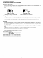
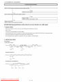
"PWBs" of this model employs lead-free solder. The LF symbol indicates lead-free solder, and is attached on the PWBs and service manuals. The
alphabetical character following LF shows the type of lead-free solder.
Example:
a
a/a
Sn-Ag-Cu
Sn-Ag-Cu
Indicates lead-free solder of tin, silver and copper.
Indicates lead-free solder of tin, silver and copper.
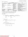
='Using lead-free wire solder
When fixing the PWB soldered with the lead-free solder, apply lead-free wire solder. Repairing with conventional
age or accident due to cracks.
lead wire solder may cause dam-
As the melting point of lead-free solder (Sn-Ag-Cu) is higher than the lead wire solder by 40 °C, we recommend you to use a dedicated soldering
bit, if you are not familiar with how to obtain lead-free wire solder or soldering bit, contact our service station or service branch in your area.
='Soldering
As the
solder
peeled
steady
melting point of lead-free solder (Sn-Ag-Cu) is about 220 °C which is higher than the conventional lead solder by 40 °C, and as it has poor
wettability, you may be apt to keep the soldering bit in contact with the PWB for extended period of time. However, Since the land may be
off or the maximum heat-resistance temperature of parts may be exceeded, remove the bit from the PWB as soon as you confirm the
soldering condition.
Lead-free
required.
solder contains more tin, and the end of the soldering bit may be easily corroded.
Make sure to turn on and off the power of the bit as
If a different type of solder stays on the tip of the soldering bit, it is alloyed with lead-free solder. Clean the bit after every use of it.
When the tip of the soldering bit is blackened during use, file it with steel wool or fine sandpaper.
Be careful when replacing parts with polarity indication on the PWB silk.
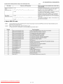
Lead-free wire solder for servicing
PRICE
RANK
PART
DELIVERY
ZHNDAi123250E
BL
J
#0.3mm 250g (1roll)
ZHNDAi126500E
BK
J
#0.6mm 500g (1roll)
ZHNDAi12801KE
BM
J
#1.0mm lkg (1roll)
PARTS CODE
Downloaded From TV-Manual.com Manuals
DESCRIPTION
LC-52LE920UN/LC-60LE920UN
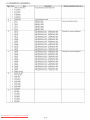
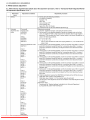
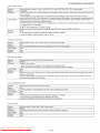
OUTLINE
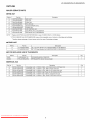
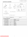
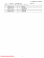
MAJOR
SERVICE
PARTS
mPWB UNIT
Ref No.
N
Part No.
DKEYMF452FM20
MAIN Unit*l
Discription
N
DUNTKF493FM01
ICON Unit
N
DUNTKF493FM02
LOGO Unit
N
DUNTKF494FM01
R/C, LED Unit
N
RUNTKA690WJQZ
TOUCH SENSOR Unit*2
N
RDENCA395WJQZ
POWER Unit
N
RUNTK4570TPZA
LCD CONTROL
N
RUNTK4433TPZA
LED DRIVE Unit (LC-52LE920UN)
N
RUNTK4433TPZZ
LED DRIVE Unit (LC-60LE920UN)
Unit
NOTE: "1 Replace MAIN PWB Units (DKEYMF452FM20)
*2 TOUCH SENSOR
Unit (RUNTKA690WJQZ)
in case of IC8455, IC8401 or IC3302 failure.
reuse will be impossible, once it is stuck on front glass and exfoliates.
Therefore, please exchange of a touch sensor unit in the case of front glass exchange.
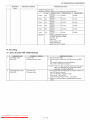
mOTHER UNIT
Ref No.
Part No.
Description
N
R1LK520D3LWB0Z
52" LCD Panel Module Unit (LK520D3LWB0Z)
(LC-52LE920UN)
N
R1LK600D3LW30Z
60" LCD Panel Module Unit (LK600D3LW30Z)
(LC-60LE920UN)
talC FOR EXCLUSIVE USE OF THE SERVICE
IC509
Ref No.
Part No.
VHiR24002AS1YS
R1EX24002ASAS0A
RGB EDID
Description
Q'ty
1
IC2002
RH-iXC786WJNHQ
R5F364A6NFB
Monitor Microcomputer
1
==SERVICE JIGS
Ref No.
Part No.
Discription
Q'ty
N
QCNW-C222WJQZ
Connecting
Cord L=1000mm
80pin LCD Control Unit to LCD Panel Unit
2
N
QCNW-H184WJQZ
Connecting
Cord L=1000mm
12pin Main to Power Unit (PD)
1
N
QCNW-F676WJQZ
Connecting
Cord L=1000mm
41pin
Main to LCD Control Unit (LW)
1
N
QCNW-G405WJQZ
Connecting
Cord L=1000mm
4pin Power to LCD Control Unit (PL)
1
N
QCNW-G394WJQZ
Connecting
Cord L=1000mm
9pin Main to LED Drive Unit (LB)
1
N
QCNW-K593WJQZ
Connecting
Cord L=1000mm
13pin Power to LED Drive Unit (LA)
1
Downloaded From TV-Manual.com Manuals
iv
LC-52LE920UN/LC-60LE920UN
CHAPTER
1. SPECIFICATIONS
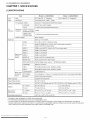
[1] SPECIFICATIONS
Item
LCD
panel
Size
52" Class (52 1/32"Diagonal)
Resolution
2,073,600
TV-standard
TV
Function
Model: LC-52LE920UN
Receiving
Channel
(CCIR)
American TV Standard ATSC/NTSC
VHF 2-13ch, UHF 14-69ch
CATV
1-135ch (non-scrambled
Digital Terrestrial
Broadcast (8VSB)
2-69ch
Digital cable .1
(64/256 QAM)
1-135ch (non-scrambled
Audio out
60" Class (60 _/32"Diagonal)
pixels (1,920 x 1,080)
VHF/UHF
Audio multi )lex
Model: LC-60LE920UN
System
channel only)
channel only)
BTSC System
10W x 2 + 15 W (WF)
Back panel
vertical
inputs
Terminals
VIDEO
AV in (0 3.5 mm to 3 RCA AV cable)
PC IN
ANALOG RGB (PC) in (15-pin mini D-sub female connector),
Audio in (0 3.5 mm stereo jack)
HDMI 1
HDMI in with HDCP, Audio in (0 3.5 mm stereo jack)
HDMI 2
HDMI in with HDCP
HDMI 3
HDMI in with HDCP
HDMI 4
HDMI in with HDCP
AUDIO IN
Audio in (0 3.5 mm stereo jack)
AUDIO OUT
Audio out (0 3.5 mm stereo jack)
DIGITAL
AUDIOOUTPUTOptical Digital audio output x 1 (PCM/Dolby
Back panel
horizontal
inputs
ETHERNET
Network connector
USB 1
Photo/Music/Video
mode, Software update
USB 2
Photo/Music/Video
mode, Software update
Digital)
COMPONENT
COMPONENT
ANT/CABLE
in
75 _ Unbalance, F Type g 1 for Analog (VHF/UHF/CATV)and
RS-232C
9-pin D-sub male connector
OSD language
English/French/Spanish
Power Requirement
AC 120 V, 60 Hz
Power Consumption
Digital (AIR/CABLE)
180 W (0.5 W Standby with AC 120 V
230 W (0.5 W Standby with AC 120 V)
TV + stand
86.0 Ibs./39.0 kg
121.3 Ibs./55.0 kg
TV only
73.9 Ibs./33.5 kg
98.1 Ibs./44.5 kg
TV + stand
49 5/8x 33 29/32x13 25/64inch
56 2_/32x 38 25/64
x 14 _/2inch
TV only
49 5/8x 31 _5/16
x 1 35/64
inch
56 2_/32x 35 6_/64
x 1 9/_6inch
Weight
Dimension .2
(WxHxD)
Operating temperature
+32°F to +104°F (0°C to +40°C)
-1 Emergency alert messages via Cable are unreceivable.
*2The dimensional drawings are shown on the inside back cover.
, As part of policy of continuous improvement, SHARP reserves the right to make design and specification changes for
product improvement without prior notice. The performance specification figures indicated are nominal values of production
units. There may be some deviations from these values in individual units.
Downloaded From TV-Manual.com Manuals
1-1
LC-52LE920UN/LC-60LE920UN
CHAPTER
2. OPERATION
MANUAL
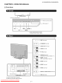
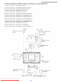
[1] Parts Name
Center Ic°n illumin!ti°n"_
_"
!
Remote control sensor
OPC sensor "I
VOL--/+
OH v/A
NPUT
POWER
MENU
2
"10PC: Optical Picture Control
*2 Using the touch sensor panel.
usB_
USB 1 terminal
(10/100)
ETHERNET
_}
®
AUDIO
--
AUDIO OUT terminal
OUT
VIDEO _
AUDIO
ETHERNET terminal
VIDEO terminal
(L/R)
PC IN terminal
ANALOG
I
AUDIO
AUDIO IN terminal
(shared for PC IN and HDMI I) *2
IN
HDMI 1 terminal
ARC: Audio Return Channel
HDMI 2 terminal
"1
HDMI 3 terminal
D
%
H_rlrH
AUO,O-OUTPUT
DIGITAL
Antenna/Cable
in
1
HDMI 4 terminal
DIGITAL AUDIO OUTPUT termina
J
RS-232C terminal
usB2
COMPONENT terminals
"1 External equipment connection.
*2 Details on the Audio Select function.
Downloaded From TV-Manual.com Manuals
_
2-1
USB 2 terminal
LC-52LE920UN/LC-60LE920UN
1
2
1
I
18
°
TV
STB
3_
External equipment
external equipment.
19
OPTION
5
SLEEP
_
PAOIWEG
R
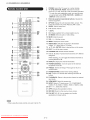
operational
buttons:
Operate the
5
OPTION: Display the Link Operation Menu screen. This
button will function only when AQUOS LINK is used.
SLEEP: Set the sleep timer.
6
0-9: Set the channel.
7
, (DOT):
DVD'VCR AUDIO
OREC
4
POWER: Switch the TV power on or enter standby.
TV, STB, DVD.VCR, AUDIO: Switches the remote
control for TV, STB, DVD, BD, VCR and AUDIO operation.
* To enter the code registration mode, you need to press
an appropriate button (STB, DVD.VCR or AUDIO) and
DISPLAY at the same time.
20
8 CC: Display
.....................................................
21
9
captions from a closed-caption source.
AV MODE: Select an audio or video setting.
10 MUTE: Mute the sound.
11 VOL +/-
: Set the volume.
12 MENU: Display the menu screen.
7
13 AQUOS NET: Switches the display to the Sidebar
Widget, TV + Web, Web or TV screen.
14 A/T/_
/ I_ ,ENTER: Select a desired item on the screen.
22
15 EXIT: Turn off the menu screen.
8
g
16 FAVORITE
17 A, B, C, D: Select 4 preset favorite channels in 4 different
categories.
11
12
While watching, you can toggle the selected channels by
pressing A,B,C and D.
18 DISPLAY:
APPS
27
13
16
17_
iii_i
_28
ii,iFAV0R,TE
_--FAVAPP
3--qo
Display the channel information.
19 POWER (SOURCE): Turns the power of the external
equipment on and off.
14
15
OH: Set the favorite channels.
20
FREEZE: Set the still image. Press again to return to
normal screen.
21
22
POWER SAVING: Select Power Saving settings.
ENT: Jumps to a channel after selecting with the 0-9
buttons.
23
FLASHBACK:
input mode.
2g
Return to the previous channel or external
24 VIEW MODE: Select the screen size.
25 INPUT: Select a TV input source. (TV, COMPONENT,
VIDEO, PC IN, HDMI 1, HDMI 2, HDMI 3, HDMI 4, USB)
26 CH v/A
: Select the channel.
27 APPS:
, When using the remote control unit, point it at the TV.
Downloaded From TV-Manual.com Manuals
2-2
Display the application window.
28
RETURN:
29
FAV APP 1, 2, 3: You can assign your favorite
applications to these buttons.
Return to the previous menu screen.
LC-52LE920UN/LC-60LE920UN
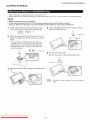
[2] OPERATION
MANUAL
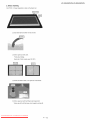
° Before attaching (or detaching) the stand, unplug the AC cord.
• Before performing work spread cushioning over the base area to lay the TV on. This will prevent it from being damaged.
• Attach the stand in the correct direction.
• Do not remove the stand from the TV unless using an optional wall mount bracket to mount it.
• Be sure to follow the instructions. Incorrect installation of the stand may result in the TV falling
1
Confirm that there are 9 screws (5 short screws
and 4 long screws) supplied with the stand unit.
2
Attach the supporting
post for the stand unit onto
the base using the box for the stand unit as shown
below.
4
Insert and tighten the 4 screws
the rear of the stand unit.
over.
into the 4 holes
_it_
on
Short screws
_9
• The supporting post attaches to the base at an offcentered location on the base. Be sure to attach the
supporting post in the direction indicated below and
attach the stand to the TV with the wider side of the
base facing forward.
_
_-_11_
Long screws
,5 (_ Insert the stand cover.
(_ Insert the screw to secure
the stand
cover.
Short screw _!!_
3
Insert the stand
TV.
into the openings
on the rear of the
Soft cushion
To detach the stand, perform the steps in reverse
order.
Downloaded From TV-Manual.com Manuals
2-3
LC-52LE920UN/LC-60LE920UN
CHAPTER
3. DIMENSIONS
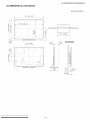
[1] DIMENSIONS
(LC-52LE920UN)
Unit: inch (mm)
49 5/8 (1260)
I
459/16(1157)
I
f
l
_g
O4
]
21
_d
1 35/64
(39)
6
_
17/64
(540)
D,,
AN-52AG4
15/64
(158)
_O
#:
o
I
_q,
I
2
41/64
13(340)
25/64
4 11/64
(106)_
Downloaded From TV-Manual.com Manuals
3-1
I
LC-52LE920UN/LC-60LE920UN
[2] DIMENSIONS
(LC-60LE920UN)
Unit: inch (mm)
56
21/32
(1439)
f
(o
t
LO
cO
15 3/4
o4
LJ
i
(400)
]
22
e,
%
27/32
1 9/16
6 55/64
(39.7)
(174)
(580)
AN =52AG4
_--
!
!
141j2
j
(368)
2
41/64
_7)
4 13/64
(106.7)
Downloaded From TV-Manual.com Manuals
3-2
I
1 9/16
LC-52LE920UN/LC-60LE920UN
CHAPTER
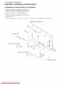
[1] REMOVING
4. REMOVING
OF MAJOR
OF MAJOR
PARTS
PARTS (LC-52LE920UN)
1. Removing of Stand Unit and Rear Cabinet Ass'y.
1. Remove the 1 lock screw _ and detach the Support Cover ®.
2. Remove the 4 lock screws ® and detach the Stand Unit _.
3. Remove the 1 lock screw ® and detach the AC Cord Cover Ch.
4. Disconnect
AC Cord _.
5. Remove the 4 lock screws ¢_, 4 lock screws ®, 1 lock screw _0_and 18 lock screws _ and detach the Rear Cabinet Ass'y @.
Rear Cabinet Ass'y
AC Cord Cover (_
Support
Cover
Stand Unit
Downloaded From TV-Manual.com Manuals
4-1
LC-52LE920UN/LC-60LE920UN
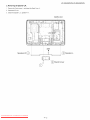
2. Removing of Speaker-L/R.
1. Remove the 2 lock screws d_ and detach the Stand Cover _.
2. Disconnect
SP wire.
3. Detach the Speaker-L ®, Speaker-R ®.
MAiN Unit
[sP]
I!
Speaker-R
_)
(_.
Cover
©
Downloaded From TV-Manual.com Manuals
4-2
Speaker-L
LC-52LE920UN/LC-60LE920UN
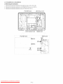
3. Removing of Connectors
1. Disconnect
the following connectors from the MAIN Unit. (SB, LB, PD, LW, RA, RL)
2. Disconnect
the following connectors from the POWER/LED
3. Disconnect
the following connectors from the LCD Control Unit. (LW, PL)
POWER
Drive Unit. (LA, PD, PL)
Unit
MAIN Unit
o o[
m_,,[LA]
o
I_ [PD]
[PL]
Downloaded From TV-Manual.com Manuals
4-3
[SB]
LC-52LE920UN/LC-60LE920UN
4. Removing of MAIN Unit, POWER Unit, Woofer, Stand Angle, 52" LCD Panel Module Unit.
1. Remove the 7 lock screws d) and detach the MAIN Unit @.
2. Remove the 2 lock screws @ and detach the Terminal Cover (Bottom) ®.
3. Remove the 2 lock screws ® and detach the Terminal Cover (Side) ®.
4. Remove the 6 lock screws ® and detach the POWER Unit ®.
5. Remove the 4 lock screws ® and detach the Sub Woofer @.
6. Remove the 1 lock screw © and detach the LCD Fixing Angle (Bottom-R)
@.
7. Remove the 2 lock screws @ and detach the LCD Fixing Angle (Top-L) @.
8. Remove the 2 lock screws @ and detach the LCD Fixing Angle (Top-R) @.
9. Remove the 2 lock screws @ and detach the LCD Fixing Angle (Bottom-L)
@.
10. Remove the 2 lock screws @ and detach the LCD Fixing Angle (B-MA) ®.
11. Remove the 2 lock screws ® and detach the LCD Fixing Angle (B-MB) @.
12. Remove the 8 lock screws @ and detach the Stand Angle @.
13. Remove the 3 lock screws ® and detach the BL Support Angle @.
14.Remove
the 6 lock screws @ and detach the 52" LCD Panel Module Unit @.
I
LCD Fixing
(Top-L)
Angle
_\
1_/1_f_5
_i
LCD Fixing Angle
(Top-R)
BL Support
Angle
Cover
Sub Woofer
52" LCD Panel
Module
Unit
8'
Stand
Angle
LCD
Fixing
Angle
(Bottom-L)
_-j @LOD
Fixing
(Bottom-R)
tLCDFixing
Angle
(B-MA) _@
@
LCD
Fixing
(B-MB)
Downloaded From TV-Manual.com Manuals
4-4
Angle
Angle
LC-52LE920UN/LC-60LE920UN
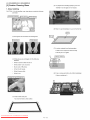
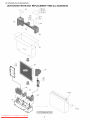
5. Removing of RIO, LED Unit, ICON Unit, LOGO Unit, Front Cabinet Ass'y, Glass Front Panel Ass'y, TOUCH
SENSOR Unit.
1. Detach the R/C, LED Unit _).
2. Detach the ICON Unit ®.
3. Detach the LOGO Unit _).
4. Remove the 28 Hooks _) and detach the Front Cabinet Ass'y (57
5. Detach the Glass Front Panel Ass'y ®).
6. Detach the Touch Sensor Unit _7._.
NOTE: The Touch Sensor unit (t) removed once is not reusable.
i_
\/
/
[RIAi'_
-_
ICON
R/C, LED
Unit
1_
......................
Unit
[Rt]_)
Glass Front Panel Ass'y
/
........................
] ........................
........................
J f........................
........................
J
t
[RK] "(_)TOUCH
Downloaded From TV-Manual.com Manuals
LOGO
SENSOR
4-5
Unit
Unit
LC-52LE920UN/LC-60LE920UN
[2] REMOVING
OF MAJOR
PARTS (LC-60LE920UN)
1. Removing of Stand Unit and Rear Cabinet Ass'y.
1. Remove the 3 lock screw _ and detach the Support Cover _2_.
2. Remove the 4 lock screws ® and detach the Stand Unit #_.
3. Remove the 1 lock screw ® and detach the AC Cord Cover ®.
4. Disconnect
AC Cord ®.
5. Remove the 4 lock screws ¢_, 7 lock screws ®7,2 lock screws _ and 18 lock screws @ and detach the Rear Cabinet Ass'y @.
Rear Cabinet Ass'y
\
\
@
AC Cord Cover __
Support Cover
Stand Unit
Downloaded From TV-Manual.com Manuals
4-6
LC-52LE920UN/LC-60LE920UN
2. Removing of Speaker-L/R.
1. Remove the 2 lock screws d) and detach the Stand Cover _).
2. Disconnect
SP wire.
3. Detach the Speaker-L ®, Speaker-R ®.
[SP]
!
Speaker-R
(_.
:_;..........................................................
._
Speaker-L
Cover
t
Downloaded From TV-Manual.com Manuals
4-7
LC-52LE920UN/LC-60LE920UN
3. Removing of Connectors
1. Disconnect
the following connectors from the MAIN Unit. (SB, LB, PD, LW, RA, RL)
2. Disconnect
the following connectors from the POWER/LED
3. Disconnect
the following connectors from the LCD Control Unit. (LW, PL)
Drive Unit. (LA, PD, PL)
POWER
Unit
LED Drive Unit
\
\
\
\
\
POWER
Unit
MAIN Unit
m_ [LA]
,,[PD]
[PL]
[SB]
[PD] .m
[LW] u
[RA]
Downloaded From TV-Manual.com Manuals
4-8
LC-52LE920UN/LC-60LE920UN
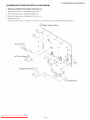
4. Removing of MAIN Unit, POWER Unit, Woofer, Stand Angle,60" LCD Panel Module Unit.
1. Remove the 7 lock screws d) and detach the MAIN Unit _).
2. Remove the 2 lock screws ® and detach the Terminal Cover (Bottom) ®.
3. Remove the 2 lock screws ® and detach the Terminal Cover (Side) ®.
4. Remove the 6 lock screws ® and detach the POWER Unit ®.
5. Remove the 4 lock screws ® and detach the Sub Woofer @.
6. Remove the 1 lock screw @ and detach the LCD Fixing Angle (Bottom-R)
@.
7. Remove the 2 lock screws @ and detach the LCD Fixing Angle (Top-L) @.
8. Remove the 2 lock screws @ and detach the LCD Fixing Angle (Top-R) @.
9. Remove the 2 lock screws @ and detach the LCD Fixing Angle (Bottom-L)
@.
10. Remove the 4 lock screws @ 2 lock screws @ and detach the 2 LCD Fixing Angle (B-MA) ® and 2 Fixing Angle (B-M2) _.
11. Remove the 12 lock screws @ and detach the 2 Stand Angle ®.
12. Remove the 3 lock screws @ and detach the BL Support Angle ©.
13. Remove the 11 lock screws @ and detach the 60" LCD Panel Module Unit @.
LCD
Fixing Angle
(Top-L)
_¢@
@_1_(_
LCD Fixing Angle
(Top-R)
)TERMINAL Cover
(Bottom)
60" LCD Panel
Module Unit
,_,1
LCD
Fixing
(Bottom-L)
Angle
_\
2_
:_
"-"
Stand
,_
Angle
(2_
_]
LCDFixingAngle
'\
(B-M2)
@
LCD
_(B-MA)
Downloaded From TV-Manual.com Manuals
4-9
@
Fixing
Angle
LCD
,1_i) LCD Fixing
(Bottom-R)
Fixing
(B-MA)
Angle
Angle
LC-52LE920UN/LC-60LE920UN
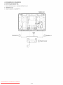
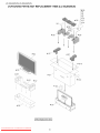
5. Removing of RIO, LED Unit, ICON Unit, LOGO Unit, Front Cabinet Ass'y, Glass Front Panel Ass'y, TOUCH
SENSOR Unit.
1. Detach the R/C, LED Unit _.
2. Detach the ICON Unit ®.
3. Detach the LOGO Unit _}.
4. Remove the 28 Hooks _b and detach the Front Cabinet Ass'y @
5. Detach the Glass Front Panel Ass'y ¢_.
6. Detach the Touch Sensor Unit ®.
NOTE: The Touch Sensor unit _h removed once is not reusable.
(_
[RIA]"(_)
Front Cabinet Ass'y
[tR]]c p
R/C,
ICON
Unit
[RL] "_
LED
Unit
_
Glass
Front
Panel Ass'y
/
:i
......................
.........................
_ o , _ o ;
__
........................
_ , _ ;
........................
.....
_ _ o _ _
;
::::::::::::::::::::::::::::::::
2
IRK] ('7)TOUCH
\d
Downloaded From TV-Manual.com Manuals
LOGO
SENSOR
4-10
Unit
Unit
LC-52LE920UN/LC-60LE920UN
[3] Caution
Cleaning
Glass
(5) Two people have handling equally by the work.
(Maintain it so that glass is not warped.)
1. Glass handling
CAUTION: (1) As for handling, wear clean gloves, protective footwear
and mask.
protective
(6) When it is put horizontally,
it is put on the flat mat.
(2) Inner gloves are covered in the Nitrile gloves.
[Inner gloves ]
INitrile gloves ]
(7) A cushion material is put between glass.
It doesn't touch it [the front and the front].
It can be put to two glass.
cushion material ]
(3) Nitrile gloves are exchanged with the following
standard.
When it touched a face and so on.
When another work was done.
By the work of fifty times.
In the time for recess.
When it became dirty.
When it tore.
(8) It has a module part before the CAB-B installation.
(It has a module part.)
changed to new Nitrile gloves
(4) It has a black mask part.
You must not have a clear surface.
\
\
\
\
Downloaded From TV-Manual.com Manuals
4-11
LC-52LE920UN/LC-60LE920UN
2. Glass cleaning
CAUTION: (1) Visual inspection is done on the black mat.
(2) Dust and trash are taken with an air blow.
(3) Dirt is wiped out with cloth.
Front side: Moufas
Back side: Cotton (clean wiper SF-30C)
(4) When dirt doesn't clean, it is wiped out with Alcohol.
(5) Dirt is wiped out with the Ethanol and clean cloth.
When wipe off a dirt the trace which wiped do not be left.
Downloaded From TV-Manual.com Manuals
4-12
LC-52LE920UN/LC-60LE920UN
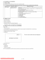
[4] How to replace
the touch
key sensor
PWB
1. Replace the touch key sensor PWB in a clean room.
Be sure to remove the dust from the unit before carrying it into the clean room.
2. Remove the touch key sensor PWB from the front glass.
3. Clean the bonding surface with alcohol.
Depending
on the dirt, water solution of 80%vol can be effective.
4. Adhere a spacer before bonding the touch unit.
Product Manual
Touch Sensor with ITO (Transparent
Electrode)
Pull tap of double-sided
i)
tape
Pull tap of protective
sheet
Remove the touch sensor from the front glass.
* When peeling the ITO section, check that there is no glue
residue on the front glass.
If glue residue, dirt, fingerprints, etc. are found, wipe them
off with anhydrous alcohol.
Do not apply anhydrous alcohol to the double-sided tape
on the metal part attaching to the glass.
ii)
Adhere the spacer to the back of the FPCB section.
i
f.j
!
Downloaded From TV-Manual.com Manuals
Space
Release paper
E
4-13
ii-1. Peel the release paper of the double-sided
tape on the FPCB section.
ii-2. Adhere the spacer to the FPCB section.
(Use the right and upper sides of the FPCB
section as a reference.)
* Check that the spacer does not contact with
the ITO section.
LC-52LE920UN/LC-60LE920UN
iii)
Adhere the ITO section to the front glass. (Use the positioning jig.)
Tape fixing the FPCB and ITO sections
(Adhered
by the supplier)
iii-1. Peel the release paper of the double-sided
on the ITO section.
tape
iii-2. Slowly adhere it from the end using a roller.
(Position the touch sensor using the jig.)
* Check that there are no bubbles in the ITO section
after adhered.
* Adhering
error: _+1.0mm
iv) Adhere the FPCB section to the front glass.
U
ill:iiiii
!
iv-1. Lift the FPCB section to peel the release paper of the
double-sided tape on the spacer.
* Be careful not to apply stress to the joint of FPCB and ITO.
iv-2. Adhere the FPCB section to the front glass.
* Be careful not to apply stress to the joint of FPCB and ITO.
iv-3. Peel the tape fixing the FPCB and ITO sections.
5. Attach the touch unit bonding procedure.
It includes peeling of the protective sheet.
How to mount the touch sensor
i)
Adhere after positioned
ii)
Peel the protective sheet by means of the pull tap for peeling the protective sheet.
using the positioning jig.
iii)
Adhere the FPCB to the glass. (Do not warp the FPCB if possible.)
Pull tap for peeling the protective
sheet of the double-sided
tape in the FPCB section. ]
--4
0000000
S: q
Downloaded From TV-Manual.com Manuals
4-14
4
",,Glass outline
LC-52LE920UN/LC-60LE920UN
iv) Peel the protective sheet of the OCA.
Lift the ITO section, then peel the protective sheet by about half by means of the pull tap.
* Peeling it completely reduces workability.
Check the order due to workability.
v)
Contact the FPCB and joint end of the transparent electrode film with the glass.
*
Grasp the opposite end. Note that the ITO is positioned by adhering.
*Note: Do not bend the PWB (FPCB section)
and sheet (ITO section).
vi) Adhere the transparent
electrode completely.
lPull tap for peeling the front protective sheet I
Peel the front protective sheet.
If bubbles are found, press those portions with glass
cleaning cloth, etc. to remove them as much as possible.
Use a rubber roller since pressure exerted by it removes bubbles easily. See photo below.
For the TOUCH SENSOR
Unit positioning figure, see page 5-1, 5-2, 5-3, 5-4.
Downloaded From TV-Manual.com Manuals
4-15
LC-52LE920UN/LC-60LE920UN
CHAPTER
5. ADJUSTMENT
[1] ADJUSTMENT
PROCEDURE
The adjustment values are set to the optimum conditions at the factory before shipping. If a value should become improper
required due to part replacement, make an adjustment according to the following procedure.
1. After replacement of any PWB unit and/or IC for repair, please note the following.
• When replacing the following units, make sure to prepare the new units loaded with updated software.
MAIN Unit:
DKEYMF452FM20
• When replacing the LCD control PWB, perform the VCOM adjustment.
2. Upgrading of each microprocessor
software
CAUTION: Never "POWER OFF" the unit when software upgrade is ongoing.
Otherwise the system may be damaged beyond recovery.
2.1. Software
version
upgrade
The model employs the following software.
Main software (please use a software version after HLI2Bxxx.USB).
Monitor microprocessor
software (please use a software version after HLI2Bxxx.USB
The main software, monitor microprocessor
The followings
2.2. Main
2.2.1
and HLNIMxxx.BIN.)
software can be upgraded by using a general-purpose
USB Memory.
are the procedures for upgrading, explained separately for the main software, monitor microprocessor
software
Get ready
version
before
software.
upgrade
you start
USB Memory of 128MB or higher capacity.
PC running on Windows 98/98SE/ME/2000/XP
USB Memory reader/writer
operating system.
or PC with a USB port.
The file system of a USB memory is FAT. (FAT32 supports)
Use the USB memory without other functions.
2.2.2
(lock and memory reader...etc)
Preparations
To upgrade the main software, it is necessary to get ready the USB Memory for version upgrade before you start.
Follow the steps below and create the USB Memory for version upgrade.
1. Copy the file HLI2Bxxx.USB
for version upgrade to the root directory (folder) of the USB Memory.
NOTE: In the USB Memory drive, do not store other folders or unrelated files, or more than one file for version upgrade.
Now the USB Memory for version upgrade is ready.
Downloaded From TV-Manual.com Manuals
5-1
or an adjustment
is
LC-52LE920UN/LC-60LE920UN
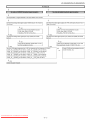
2.2.3
How
to upgrade
the software
1. Plug AC cord and turn on the TV.
2. After picture displayed, touch the power key for 5seconds.
NOTE: Picture will disappear when you touch the power key, but keep touching it.
3. When the center icon LED blinks, release your finger from the power key.
4. Next, touch the "POWER" and "CH (/-,,)"
keys at the same time.
5. When the center icon LED turns on, release your finger form the keys.
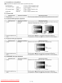
6. After the unit startup, the system upgrade screen as shown below within 20-40 seconds.
7. Even a single failure in the process will trigger the upgrade failure screen.
NOTE: In the event of a failure, repeat the upgrade process. If the process repeatedly fails, it is likely that the hardware need fixing.
8. Upon completion of the whole process, the upgrade success screen as shown below appears. You can check the new software version on this
screen. The version information appears after the upgrade is complete.
9. Unplug the AC cord and remove the USB Memory for version upgrade.
10.Now the software version upgrade is complete.
NOTE: When you are done with the software version upgrade, start the set, go to the top page of the adjustment
software version information.
Downloaded From TV-Manual.com Manuals
5-2
process screen and check the main
LC-52LE920UN/LC-60LE920UN
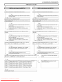
2.3. Monitor
microprocessor
software
version
Create the USB memory for monitor microprocessor
upgrade".
Copy the file HLI2Bxxx.USB
2.3.1
How to upgrade
and HLNIMxxx.BIN
upgrade
software version upgrade
(named temporarily)
in the same manner
for monitor microprocessor
as explained
in the "Main software version
software version upgrade to the USB memory.
the software
1. Plug AC cord and turn on the TV.
2. After picture displayed, touch the power key for 5seconds.
NOTE: Picture will disappear when you touch the power key, but keep touching it.
3. When the center icon LED blinks, release your finger from the power key.
4. Next, touch the "POWER" key with the "CH (/'_)"
key touching.
5. When the center icon LED turns on, release your finger form the keys.
CAUTION: •
•
The moment this operation is done, the upgrading of the monitor microprocessor software starts. While the upgrade is ongoing, never
power off the unit. Otherwise the upgrade will fail and the system may be serious damaged beyond recovery (inability to start).
After the monitor microprocessor
software is upgraded, also perform the 'Industry Init'.
6. After the unit startup, the upgrade starts. The power led will blink continuously.
Also, an upgrade screen will be shown during a minor upgrade.
7. If the upgrade fails, power led will stop blinking. Also, the upgrade failure screen will be shown if upgrade screen was shown at 5.
NOTE: In the event of a transient failure, upgrade will be automatically
cause.
retried up to three times. If the process repeatedly fails, hardware may be the
8. The upgrade success screen will be shown if upgrade screen was shown at 5.
9. Unplug the AC cord and remove the USB Memory for version upgrade.
10.Now the software version upgrade is complete.
NOTE: When you are done with the software version upgrade, start the set, go to the top page of the adjustment process screen and check the monitor microprocessor software version information and panel size information.
Downloaded From TV-Manual.com Manuals
5-3
LC-52LE920UN/LC-60LE920UN
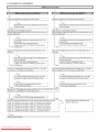
3. Entering and exiting the adjustment process mode
1) Before entering the adjustment
process mode, the AV position RESET in the video adjustment menu.
2) At the state TV is turned on, touch the power key for 5seconds.
NOTE: Picture will disappear when you touch the power key, but keep touching the power key.
3) When the center icon LED blinks, release your finger from the power key.
4) Next, touch the "POWER" key with the "VOL (1)" and "INPUT" key touching.
TV will turn on and the letter "<K>" appears on the screen.
5) Next, touch the "VOL (1)" and "CH (v)"
keys at the same time.
6) When the center icon LED turns on, release your finger form the keys.
(The "VOL (1)" and "CH (v)"
keys should be pressed and held until the display appears.)
Multiple lines of blue characters appearing on the display indicate that the unit is now in the adjustment
When you fail to enter the adjustment
process mode.
process mode (the display is the same as normal startup), retry the procedure.
7) To exit the adjustment process mode after the adjustment is done, unplug the AC cord from the outlet to make a forced shutdown. (When the
power was turned off with the remote controller, once unplug the AC cord and plug it again. In this case, wait 10 seconds or so before plugging.)
CAUTION: Use due care in handling the information described here lest your users should know how to enter the adjustment
settings are tampered in this mode, unrecoverable system damage may result.
4. Remote controller key operation and description of display in adjustment process mode
1) Key operation
Remote controller key
CH (V/_-,
Function
Main unit key
CH (V
)
VOL (+/-)
//'\
)
VOL (+/-)
Moving an item (line) by one (UP/DOWN)
Changing a selected item setting (+1/-1 )
Cursor (UP/DOWN)
Turing a page (PREVIOUS/NEXT)
Cursor (LEFT/RIGHT)
INPUT
Changing a selected line setting (+10/-10)
ENTER
Executing a function
Input switching (toggle switching)
*Input mode is switched automatically
when relevant adjustment
is started so far as the necessary input signal is available.
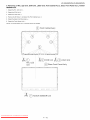
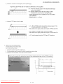
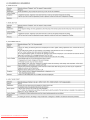
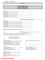
2) Description of display
(2) Current selected input
(3) Current color system
(1) Current page/
Total pages
J
i?/24
!NPUT5
J
(4) Destination
L
AUTO
USA
BOOT Version
LC-52LE920UN
Monitor/Monitor BOOT Version
1.02 / 1.00
(HLI2080)/LC-60LE920UN
LCD CON Version / LED CON Version
20100114f2014681/00
Netflix ESN
ERR
FRC-N Auto Scrip! Version
0912090000000000
(5) LCD Panel size/Speaker
[
52 UNDER
_--
(6) Adjustment
process menu
header
(HLI2100)
I
! TCON Master / Slave Serial Version
TOUCH SENSOR
UCON VERSION
20100114f2014681/20100114f2014681
B00ZD012110
TEMPERATURE
66
LAMP ERROR
0
MONITOR
ERR CAUSE
NORMAL STANDBY CAUSE
ERROR STANDBY
CAUSE
Downloaded From TV-Manual.com Manuals
1) 00 0000000000000
2) 00 0000000000000
3) 00 0000000000000
4) 00 0000000000000
0
50 50 50 50 0
5-4
type
(7) Parameters
process mode. If the
LC-52LE920UN/LC-60LE920UN
5. List of adjustment process mode menu
The character string in brackets [ ] will appear as a page title in the adjustment process menu header.
Page
1
2
3
4
5
6
Line
1
MAIN Version
Item
Description
Main software version
2
3
BOOT Version
Monitor/Monitor
4
LCD CON Version / LED CON Version
BOOT Version
Monitor and monitor boot software version
5
Netflix ESN
6
7
FRC-N Auto Script Version
TCON Master/Slave Serial Version
8
TOUCH SENSOR UCON VERSION
9
TEMPERATURE
Panel temperature
10
LAMP ERROR
Number of termination due to lamp error
11
MONITOR ERR CAUSE
12
NORMAL STANDBY CAUSE
13
ERROR STANDBY CAUSE
INIT
LCD controller software version
detail, etc.)
Versions are always '090626000T0001
'.
Audio data checksum
Refer to "1 under the list for details
Refer to *2 under the list for details
1
INDUSTRY
2
3
INDUSTRY INIT(-Public)
PUBLIC MODE
4
Center Acutime
RESET
Accumulated
Reset
main operation time
5
6
7
Backlight Acutime
RESET
Accumulated
Reset
monitor operation time
8
LAMP ERROR RESET
Reset LAMP ERROR
9
VIC XPOS
X-coordinate
setting for VIC READ
10
VIC YPOS
Y-coordinate
setting for VIC READ
11
VIC COLOR
Collected color data setting for VIC READ
12
VIC SIGNAL TYPE
Signal type setting for VIC READ
13
VIC READ
Picture level acquisition function
1
N358 ALL ADJ(INPUT2)
CVBS and TUNER signal level adjustment
2
3
4
N358 MAIN ADJ(INPUT2)
TUNER DAC ADJ
N358 CONTRAST A GAIN
CVBS signal level adjustment
5
N358 CONTRAST
D GAIN
6
N358 CONTRAST
OFFSET
7
TUNER CONTRAST
8
TUNER CONTRAST
D GAIN
9
TUNER CONTRAST
OFFSET
Initialization
to factory settings
Public mode
TUNER signal level adjustment
A GAIN
1
TUNER VCHIP TEST(69ch)
Tuning test and VCHIP test (69ch)
2
TUNER VCHIP TEST(7ch)
Tuning test and VCHIP test (7ch)
3
TUNER VCHIP TEST(10ch)
Tuning test and VCHIP test (10ch)
4
5
TUNER VCHIP TEST(15ch)
INSPECT USB TERM
Tuning test and VCHIP test (15ch)
6
7
HDMI EDID WRITE
HDMI CEC TEST
1
2
COMP15K ADJ(INPUT1)
COMP15K Y A GAIN
3
COMP15K Cb A GAIN
4
COMP15K Cr A GAIN
5
6
COMP15K Y OFFSET
COMP15K Cb OFFSET
7
COMP15K Cr OFFSET
1
2
COM P33K ADJ(IN PUT1 )
COMP33K Y A GAIN
3
COMP33K Cb A GAIN
4
5
COMP33K Cr A GAIN
COMP33K Y OFFSET
6
COMP33K Cb OFFSET
7
COMP33K Cr OFFSET
Downloaded From TV-Manual.com Manuals
Remarks (adjustment
Component
15K picture level adjustment (main)
Component
33K picture level adjustment (main)
5-5
Level appears in green on the upper right
LC-52LE920UN/LC-60LE920UN
Page
7
8
9
10
11
12
13
Line
1
Item
ANALOG RGB ADJ
2
3
R A GAIN
G A GAIN
4
B A GAIN
5
R OFFSET
6
G OFFSET
Description
Remarks (adjustment
7
B OFFSET
1
1
VCOM ADJ
LEV1
VCOM adjustment
Standard value 1
2
LEV2
Standard value 2
3
LEV3
Standard value 3
4
LEV4
Standard value 4
5
LEV5
Standard value 5
6
LEV6
Standard value 6
1
MG1R
WB adjustment
Point 1, R adjustment value
2
MG1G
WB adjustment
Point 1, G adjustment
value
3
MG1B
WB adjustment
Point 1, B adjustment
value
4
MG1Y
WB adjustment
Point 1, Y adjustment
value
5
MG2R
WB adjustment
Point 2, R adjustment value
6
MG2G
WB adjustment
Point 2, G adjustment
value
7
MG2B
WB adjustment
Point 2, B adjustment
value
8
MG2Y
WB adjustment
Point 2, Y adjustment
value
9
MG3R
WB adjustment
Point 3, R adjustment value
10
MG3G
WB adjustment
Point 3, G adjustment
value
11
MG3B
WB adjustment
Point 3, B adjustment
value
12
MG3Y
WB adjustment
Point 3, Y adjustment
value
1
MG4R
WB adjustment
Point 4, R adjustment value
2
MG4G
WB adjustment
Point 4, G adjustment
value
3
MG4B
WB adjustment
Point 4, B adjustment
value
4
MG4Y
WB adjustment
Point 4, Y adjustment
value
5
MG5R
WB adjustment
Point 5, R adjustment value
6
7
MG5G
MG5B
WB adjustment
Point 5, G adjustment
value
WB adjustment
Point 5, B adjustment
value
8
MG5Y
WB adjustment
Point 5, Y adjustment
value
9
MG6R
WB adjustment
Point 6, R adjustment value
10
MG6G
WB adjustment
Point 6, G adjustment
value
11
12
MG6B
MG6Y
WB adjustment
Point 6, B adjustment
value
WB adjustment
Point 6, Y adjustment
value
13
MG6Y OFFSET
1
MODE SELECT
2
POS SELECT
3
POS MIN
4
5
POS MID1
POS MID2
6
POS MID3
7
POS MID4
8
POS MID5
9
POS MID6
10
1
POS MAX
CD MIN
2
CD MID1
3
CD MID2
4
CD MID3
5
CD MID4
6
7
CD MID5
CD MID6
8
CD MAX
Downloaded From TV-Manual.com Manuals
detail, etc.)
Analog RGB picture level adjustment
value
5-6
Adjustment gradation setting.
Parameter for six-point adjustment
Parameter for six-point adjustment
LC-52LE920UN/LC-60LE920UN
Page
14
15
16
17
18
19
20
21
22
Line
1
CAL C
Item
Description
2
3
RESET
VAL1
4
VAL2
5
VAL3
6
VAL4
7
VAL5
8
1
VAL6
MONITOR TIME OUT
2
MONITOR MAX TEMP
3
MONITOR ERROR CAUSE RESET
1
LCD TEST PATTERN
2
LCD TEST PATTERN1
3
LCD TEST PATTERN2
4
LCD TEST PATTERN3
5
LCD TEST PATTERN4
6
TV TEST PATTERN 1
7
TV TEST PATTERN 2
1
FRC-N Firmware Version
2
3
FRC-N Boot Script Version
FRC-N Device Version
4
TCON FPGA1 Serial Flash Version
5
TCON FPGA2 Serial Flash Version
6
TCON FPGA1 Config Rom Version
7
1
TCON FPGA2 Config Rom Version
READ/WRITE
2
SLAVE ADDRESS
3
RESISTER ADDRESS
UPPER
4
RESISTER ADDRESS
LOWER
5
WRITE DATA UPPER
6
WRITE DATA LOWER
7
8
READ DATA UPPER
READ DATA LOWER
1
POWER LED BRIGHTNESS
2
MENU LED BRIGHTNESS
3
INPUT LED BRIGHTNESS
4
5
CH UP LED BRIGHTNESS
CH DOWN LED BRIGHTNESS
6
VOL UP LED BRIGHTNESS
7
VOL DOWN LED BRIGHTNESS
8
LOGO LED BRIGHTNESS
9
ICON LED BRIGHTNESS
10
ICON LED BRIGHTNESS
1
(STANDBY)
POWER KEY SENSITIVITY
2
MENU KEY SENSITIVITY
3
INPUT KEY SENSITIVITY
4
5
CH UP KEY SENSITIVITY
CH DOWN KEY SENSITIVITY
6
VOL UP KEY SENSITIVITY
7
VOL DOWN KEY SENSITIVITY
1
KEY STRENGTH GET MODE
2
POWER KEY STRENGTH
3
4
MENU KEY STRENGTH
INPUT KEY STRENGTH
5
CH UP KEY STRENGTH
6
CH DOWN KEY STRENGTH
7
VOL UP KEY STRENGTH
8
VOL DOWN KEY STRENGTH
1
2
3
KEY LOCK (1217)
KOUTEI AREA ALL CLEAR
A MODE AREA CLEAR
4
BACKUP AREA CLEAR
5
B MODE AREA CLEAR
6
EXECUTION
Downloaded From TV-Manual.com Manuals
5-7
Remarks
(adjustment
detail, etc.)
LC-52LE920UN/LC-60LE920UN
Page
23
24
Line
Item
Description
1
ERROR STANDBY CAUSE1
2
3
ERROR STANDBY CAUSE2
ERROR STANDBY CAUSE3
4
ERROR STANDBY CAUSE4
5
ERROR STANDBY CAUSE5
6
ERROR STANDBY CAUSE RESET
1
EEP SAVE
Writing setting values to EEPROM
2
3
EEP RECOVER
MODEL NAME
Reading setting values from EEPROM
4
PANEL SIZE
5
SETTING FOR ADJ
6
PANEL LIMIT
7
PANEL RANGE LIMIT
8
SHORT CHECK MODE
9
SHORT CHECK CURRENT
10
CURRENT SW
"1 Details of P1.9 (NORMAL
STANDBY CAUSE)
2
No operation off
3
No signal off
in the cause of "no operation off"
4
PC power management
mode 1
in the cause of "Standby mode MODEl"
5
6
PC power management
Off timer
mode 2
in the cause of "Standby mode MODE2"
in the cause of "SLEEP timer"
8
Command from RS232C
in the cause of "no signal off"
*2 Details of P1.10 (ERROR STANDBY
in the cause of command
CAUSE)
Prolonged unspecified-signal
17
1A
Temperature error
Monitor trouble detected
input in PC mode
in the cause of abnormal temperature
in the cause of abnormal monitor mode
22
LCD controller
in the cause of software abnormality of LCD controller
Rom error
in the cause of continuous
STANDBY CAUSE (Page 1/24)
Display of a cause (code) of the last standby
The cause of the last standby is recorded in EEPROM whenever
possible.
Checking this code will be useful in finding a problem when you repair the troubled set.
*
EEP SAVE (Page 24/24)
Storage of EEP adjustment value
*
by RS-232C
11
6. Special features
*
Remarks (adjustment
EEP RECOVER (Page 24/24)
Retrieval of EEP adjustment value from storage area
Downloaded From TV-Manual.com Manuals
5-8
"out of range", PC input mode
detail, etc.)
LC-52LE920UN/LC-60LE920UN
7. Microprocessor
7.1. Main
software writing
microprocessor/monitor
Adjustment
microprocessor
item
Main microprocessor/monitor microprocessor software writing
<Main PWB>
Adjustment
software
writing
(Main
conditions
PWB:
QPWBXF452WJZZ)
Adjustment
Software Version Up
procedure
1. Insert a USB memory for the main/monitor
Rector.
microprocessor
into the service con-
2. Supply AC power and write the main software to IC8401 and the monitor microprocessor software to IC2002.
3. Check that writing is normally completed and turn off the power.
File version check
USB memory check
CAUTION: When the USB memory is not inserted or reading error occurs, nothing
is written. (The former models have read the main software from the
writing jig. However, this model reads the main/monitor software from
the USB memory.)
*
7.2. Model/inch
discrimination
When IC is failure
writing
When writing the sub microprocessor
(Main
PWB:
Please exchange to another PWB unit when IC8401 (NAND Flash) is failure.
(Because the software can't be written with USB memory, when the new IC is
exchanged from broken IC)
QPWBXF452WJZZ)
software, the model data is configured with the software from the USB memory mounted to the checker.
Reference and setting change are enabled through the process menu and RS-232C communication.
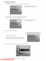
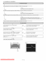
8. Signal adjustment
8.1. LCD section adjustment
Adjustment
item
Opposite bias adjustment
(LCD module adjustment
item)
[LCD module adjustment]
Adjustment
conditions
Adjustment in the center
position of the panel
Adjustment
procedure
1. Enter the process mode using the process adjustment remote control.
2. Select [VCOM ADJ] using the Channel ./_/v
keys on the remote control.
3. Press the Enter key to check that the pattern for adjustment is displayed.
4. Make adjustment so that the flicker located in the center of the screen is minimized using the Volume +/- keys on the remote control.
5. If the optimum condition is obtained in step 4, press the Enter key to turn off the
pattern.
CAUTION: * Make adjustment with no ANT signal (since the brightness is
changed by the active backlight).
[Adjustment
position]
3/4
//I
i
i
i
8.2. Image adjustment
8.2.1 Device check
[] Before adjustment, check that the adjustment jig and signal source are set for Sharp LCD US.
Signal adjustment works at only the default View Mode.
Before adjustment,
confirm the View Mode is set as follows.
Adjustment Type
Default View Mode
Composite/Tuner
S.Stretch
Compl 5k
S.Stretch
Comp33k
Stretch
Analog RGB
Stretch
Downloaded From TV-Manual.com Manuals
5-9
LC-52LE920UN/LC-60LE920UN
[] Signal generator level adjustment check (Adjust to the standard value level.)
•Composite
signal:
0.714Vp-p + 0.02Vp-p (Pedestal to white)
Y level:
0.714Vp-p+ 0.02Vp-p (Pedestal to white)
PB/PR level:
0.7Vp-p + 0.02Vp-p
•33K component signal:
Y level:
0.7Vp-p + 0.02Vp-p (Pedestal to white)
0.7Vp-p + 0.02Vp-p
•Analog RGB:
PB/PR level:
RGB level:
• 15K component
8.2.2
Process
signal:
mode
Adjustment
Process
mode
8.2.3 Composite
point
N358
Adjustment
1
0.7Vp-p + 0.02Vp-p (Pedestal to white)
Adjustment
signal/tuner
point
Enter the process adjustment Adjustment
mode using procedure
the process adjustment remote control.
adjustment
Adjustment
Setting
conditions
conditions
N358 signal
US-10ch
Adjustment
procedure
•Send the N358 color bar (color saturation: 75%) signal to the Video 2 video input.
•Send the in-house signal (use US-10ch) to TUNER.
[Video input signal]
[In-house
US-10ch]
Color saturation: 75%
1` 100% white
2
Automatic
cution
adjustment exe-
8.2.4 Component
15K signal
Adjustment
1
1"0% black
1"100% white
Point the cursor to [111N358ALL ADJ(INPUT2)] and press the [Enter] key.
The adjustment is complete when [mN358 ALL ADJ(INPUT2) OK] is displayed.
adjustment
point
Setting
Adjustment
conditions
480i signal
Adjustment
procedure
,Send the 100% color bar signal to the Video 1 component
input.
100% color bar
480i
1" 100% white
2
Automatic adjustment execution
8.2.5 COMPONENT
Adjustment
1
33K signal
point
Setting
1"0% black
Point the cursor to [mCOMP15K ADJ(INPUT1 )] and press the [Enter] key.
The adjustment is complete when [1!1COMP15K ADJ(INPUT1) OK] is displayed.
adjustment
Adjustment
1080i signal
conditions
Adjustment
procedure
,Send the 100% color bar signal to the Video 1 component
Color saturation: 100%
__
1" 100% white
2
Automatic adjustment
cution
exe-
Downloaded From TV-Manual.com Manuals
1080i
100% color bar
1` 0% black
Point the cursor to [mCOMP33K ADJ(INPUT1)]
The adjustment is complete when [mCOMP33K
5-10
input.
and press the [Enter] key.
ADJ(INPUT1 ) OK] is displayed.
LC-52LE920UN/LC-60LE920UN
8.2.6 Analog RGB signal adjustment
Adjustment
point
Setting
Adjustment
conditions
Signal: XGA
(1024x768) 60Hz
SYNC: HV separate
Adjustment procedure
• Send the 100% color bar signal to the Video 4 analog RGB input.
XGA (1024x768)
100% color bar
1" 100% white
2
Automatic adjustment execution
8.2.7 Tuner/V-CHIP
Adjustment
1"0% black
Point the cursor to [mANALOG RGB ADJ] and press the [Enter] key.
The adjustment is complete when [IIIANALOG RGB ADJ OK] is displayed.
adjustment
point
1
Setting
2
Automatic adjustment
cution
Adjustment
conditions
NTSC RF signal
US-7(AIR)ch
exe-
Downloaded From TV-Manual.com Manuals
Adjustment
procedure
,Send the NTSC signal to the RF antenna input.
Point the cursor to [mTUNER VCHIP TEST(*07ch)] and press the [Enter] key. (*
Adjust the selected channel to the in-house signal.)
The adjustment is OK when [mA-OK(***.**)/VM-OK]
is displayed in green.
(NG when A-NG/VM-NG is displayed in red.)
It is OK when the deviation from the center frequency is +0.0625MHz or less.
5-11
LC-52LE920UN/LC-60LE920UN
9. White
balance
adjustment
9.1. White balance adjustment (For details about the adjustment
WB Adjustment Specification Vl.92".)
Adjustment
point
1
Adjustment
conditions
Setting
procedure,
refer to "Kameyama
Adjustment
Model Integrated
Monitor
procedure
1) Set the unit to the following conditions.
AV MODE: [DYNAMIC]
Backlight: +16
OPC: OFF
Active Contrast: OFF
Power Saving: OFF
Aging Time: Min. 60 minutes
2) Connect the unit with the white balance adjustment jig.
Automatic
adjustment execution
[Command]
Process mode
KRSW0001
KKT10037
Setting
KYOF0000
0SDS0001
SBSL0016
Multi-point adjustment mode
MSET0011
Point 6
LEV60229
MG6G ....
MG6B ....
MG6R ....
MG6Y ....
Point 5
LEV50173
MG5G ....
MG5B ....
[Adjustment procedure]
1) Send the "adjustment process" code using the remote control.
2) Set the point 6 to the specified gradation, specify the strongest color as the fixed
color, and adjust the RGB so that it becomes the standard value through negative
adjustment. Then compare the R and G values; based on the result, calculate the Ye
value in the following conditions.
R > G: Ye = G x 1.05
R < G: Ye = R x 1.05
*
If the Ye value exceeds the initial value (input gradation x 4), it is rounded to that
value or less.
3) Set the point 5 to the specified gradation, set the G correction value (692 x G value of
point 6/916) (fractions rounded off) and the Ye correction value (692 x Ye value of
point 6/916) (fractions rounded off), and adjust the RB so that it becomes the standard value.
4) Set the point 4 to the specified gradation, set the G correction value (532 x G value of
point 6/916) (fractions rounded off) and the Ye correction value (532 x Ye value of
point 6/916) (fractions rounded off), and adjust the RB so that it becomes the standard value.
5) Set the point 3 to the specified gradation, set the G correction value (464 x G value of
point 6/916) (fractions rounded off) and the Ye correction value (464 x Ye value of
point 6/916) (fractions rounded off), and adjust the RB so that it becomes the standard value.
MG5R ....
MG5Y ....
6) Set the point 2 to the specified gradation, set the G correction value (296 x G value of
point 6/916) (fractions rounded off) and the Ye correction value (296 x Ye value of
point 6/916) (fractions rounded off), and adjust the RB pattern so that it becomes the
standard value.
Point 4
LEV40133
MG4G ....
7) Set the point 1 to the specified gradation, set the G correction value (180 x G value of
point 6/916) (fractions rounded off) and the Ye correction value (180 x Ye value of
point 6/916) (fractions rounded off), and adjust the RB so that it becomes the standard value.
MG4B ....
MG4R ....
MG4Y ....
Point 3
LEV30116
MG3G ....
MG3B ....
MG3R ....
8) Write the adjustment value by the MSET0003 command and turn off the AC power.
* RGB initial value of point 6: Set gradation 916
* RGB initial value of points 1 to 5: G correction value of each point
(At each point, make adjustment so that the remainder of the RGB adjustment value/
4 is equal.)
[Adjustment value]
* According to the "Standard settings" submitted by the Technical Department
[LC52LE920UN] LE920 model teaching set
MG3Y ....
Point 2
LEV20074
MG2G ....
MG2B ....
MG2R ....
MG2Y ....
Point 1
L EV 10045
MG1G ....
MG1B ....
MG1R ....
MG1Y ....
Writing
MSET0003
Downloaded From TV-Manual.com Manuals
5-12
LC-52LE920UN/LC-60LE920UN
Adjustment
point
Adjustment
conditions
Adjustment
procedure
[Adjustment standard value]
Measuring instrument: [Minolta CA-210] Technical measuring
Level
Point 6
Point 5
Point 4
Point 3
Point 2
Point 1
916
692
532
464
296
180
Reference value
X=0.272
Adjustment
y=0.277
X=0.272
y=0.277
X=0.272
y=0.277
X=0.272
y=0.277
X=0.272
y=0.277
X=0.272
instrument
spec
Inspection spec
±0.0010
±0.0020
±0.0010
±0.0020
±0.0015
±0.0030
±0.0020
±0.0040
±0.0030
±0.0060
±0.004
±0.0080
y=0.277
Remarks
Setting conditions for inspection
AV MODE: [DYNAMIC] (Reset)
Monochro: ON
OPC: OFF
Active Contrast: OFF
Power Saving: OFF
Aging Time: Min. 60 minutes
10. Key writing
10.1. EDID writing (Main PWB: QPWBXF452WJZZ)
Adjustment
point
HDMI EDID writing
(Main PWB)
Adjustment
conditions
Process mode
Model discrimination check
Adjustment
procedure
1) Enter the process mode.
2) Point the cursor to [HDMI EDID WRITE] and press the [ENT]
key.
The writing is complete when [OK] is displayed.
(If not written, HDMI does not function.)
CAUTION: Perform the data writing after setting the model discrimination. The data based on the model discrimination
information is recorded in EEPROM.
Analog RGB EDID writing
(Main PWB)
Inspection mode
File version check
1) Write the EDID data
main PWB using the
TL511 *** 12C clock,
TL544 *** 5V, TL507
for analog RGB into IC509 mounted on the
checker.
TL508 *** 12C data
*** GND
TL585 °°° Write protection (H: WP, L: write enable)
2) Perform the data writing before making inspection using the
checker.
Downloaded From TV-Manual.com Manuals
5-13
LC-52LE920UN/LC-60LE920UN
11. Factory setting
After completing the factory setting, pull out the AC cord to complete the setting.
CAUTION: Do not turn on the power after completinq the factory settinq. If the power is turned on, confiqure the factory settinq aqain.
Adjustment
1
point
Factory setting
Adjustment
conditions
Complete the setting by
pulling out the AC cord.
Adjustment
procedure
• Point the cursor to [INDUSTRY INIT], set to "ON" using [+]/[-] of the [VOL] key, and press
the [ENT] key.
The version confirmation screen appears on the green screen. It is completed when [SUCCESS] is displayed at the top.
(if error occurs, [ERROR] is displayed on the red screen.)
• Turn off the AC power.
The following items are initialized when configuring the factory setting.
1) User set value
2) Channel data (broadcasting frequency, etc.)
3) Password setting value
4) Operating time
5) StandbyCause
6) Auto installation flag
7) V-CHIP block setting value
12. Software version
1. Main microcomputer
2. Monitor microcomputer
3. EDID data (Analog RGB)
4. (Reference:
File name in the Technical Department)
For analog RGB
13. Writing
Input3: IC509: edid_dsub15_fullhd
v6 256.BIN
the inch and model name onto EEPROM
Writing method
1. Pull out the AC cord.
2. Copy the application for writing inch/model
name (HLI2MA01 .USB) and model/inch
file (52LE920.MDL)
to the USB memory.
3. Hold down the power button and insert the AC cord.
4. Release the power button after 5 seconds.
5. Update starts.
LE920
UPGRADE
The inch and model name are displayed.
SUCCESS
6. Pull out the AC cord.
Model/inch file
52LE920.MDL
60LE920.MDL
*
32 inch is not necessary.
NOTE: When replacing the main PWB, make sure to perform the writing the inch and model name onto EEPROM
Downloaded From TV-Manual.com Manuals
5-14
LC-52LE920UN/LC-60LE920UN
[2] PUBLIC
MODE SETTING
PROCEDURE
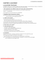
1. How to start Public Mode
• There are the following 3 ways to get the public mode setup screen displayed.
In the adjustment
process mode, turn on "PUBLIC MODE"
1) Plug AC cord and turn on the TV.
2) After picture displayed, touch the "POWER" key for 5seconds.
NOTE: Picture will disappear when you touch the power key, but keep touching it.
3) When the center icon LED blinks, release your finger from the power key.
4) Next, touch the "POWER" key with the "CH (/-_)"
key and "VOL (+)" key touching.
5) When the center icon LED turns on, release your finger form the keys.
® It's same as (_ from 1) to 3)
4) Next, touch the "POWER" key with the "INPUT" key and "CH (/-,-)"
key touching.
5) When the center icon LED turns on, release your finger form the keys.
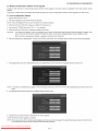
6) Get the password input screen displayed.
Procedure
,, The input starts with the leftmost digit.
• Use the numeric keys [1] thru [9] and [0] keys on the remote controller.
The other keys are not acceptable.
• With a numeric-key input, "-" will change to "_".
The input position will move one digit to the right.
• With all the 3 digits entered, the password will be verified.
7) The 3-digit password is now verified.
The password
[0] [2] [7] provides for the public mode screen. (This screen comes on with whatever adjustment
process settings.)
With any other passwords, the screen changes to the normal mode.
2. How to exit Public Mode
There are the following ways to quit the public mode setup screen.
• Turn off "PUBLIC MODE" in the adjustment
process mode. (-#) _ This way alone is not for quitting the setup screen, but for quitting the mode itself.
• Turn off the power with the "POWER" key. (-k)
• Select "EXECUTE".
(-k)
-k ... "PUBLIC MODE" stays on in the adjustment process mode.
#...
The settings will be back to the factory ones.
3. Public Mode Setting Values
• With the factory settings made, the public mode settings get initialized. (The adjustment
Downloaded From TV-Manual.com Manuals
5-15
process remains intact.)
LC-52LE920UN/LC-60LE920UN
4. Public Mode Menu
The guidance is not displayed on screen.
Setup procedure
• To move the cursor up and down, use the "cursor UP/DOWN" key (remote controller) and "CH ( _
)/( V
)" key (remote controller and set).
• To change the settings, use the "cursor RIGHT/LEFT"
key (remote controller) and "VOL (+)/(-)" key (remote controller and set).
• To save new settings, keep the cursor at "EXECUTE"
and use "ENTER" key (remote controller
PUBLIC
MODE
POWER ON FIXED
[VARIABLE
MAXIMUM
[
VOLUME
60
VOLUME
FIXED
[VARIABLE
VOLUME
FIXED LEVEL
[
20
RC BUTTON
[RESPOND
PANEL BUTTON
[RESPOND
MENU BUTTON
[RESPOND
AV POSITION
FIXED
ON SCREEN
DISPLAY
[VARIABLE
[YES
INPUT MODE
START
[NORMAL
INPUT MODE
FIXED
[VARIABLE
LOUD SPEAKER
[ON
RC_PATH_THROUGH
[OFF
232C POWON
[DISABLE
PUBLIC
[OFF
MODE
RESET
EXECUTE
Downloaded From TV-Manual.com Manuals
5-16
]
]
]
]
]
]
]
]
]
]
]
]
]
]
]
and set).
LC-52LE920UN/LC-60LE920UN
5. On Setting Items
* "EZ-SETUP"
discussed below indicates "EZ-SETUP after the first power-on".
1) POWER ON FIXED
Selection
Selection between "Variable" and "Fixed" (loop provided)
Default
- (Variable)
Explanation
In "Fixed" setting, the power-off by the power key of the unit is invalidated and the image is kept being received. The power can
be turned off by stopping the power supply from AC.
Limit in Setting
Refer to the "Power-On
Exception
None
Remarks
• In "Variable" setting, the power operation is in wait for 1 sec. and then turned off when the main power switch is off.
2) MAXIMUM
Fixed" sheet.
VOLUME
Selection
Default
Adjustment
60
from 0 to 60 (no loop)
Explanation
Sound volume can not be adjusted higher than the preset value.
Limit in Setting
• When the sound volume is set lower than 59, only figures are displayed and the sound volume bar is not displayed.
• The maximum sound volume for ON-timer (Wake up timer) is limited also to the preset value.
Exception
Remarks
• When the sound volume is set higher than the MAX setting by the adjusting process, the sound volume control operation is
prohibited for turn-up and the sound volume should be turned down to MAX in this state.
3) VOLUME FIXED
Selection
Default
Selection between "Variable", "Fixed", "ACON (AC CTRL)" and "AC/RCON
Variable
(AC/RC CTRL)" (loop provided)
Explanation
• FIXED: Fixed at the level adjusted for a fixed volume.
• AC CTRL: Start-up at the level specified for a fixed volume at ACON.
• AC/RC CTRL: Start-up at the level specified for a fixed volume at start.
Limit in Setting
• The sound volume for the ON-timer (Wake up timer) is fixed also without display of menu. Besides, the setting is made
impossible. (Basically, the menu is not displayed.)
• The following keys become invalid:
• Sound volume Up/Down (VOL +!-) [for both remote control and the unit]
• Mute (MUTE)
Exception
• In the item "VOLUME" of adjustment
Remarks
• As for sound volume fixing and sound volume MAX level, the sound volume fixing has priority.
• Once the sound volume has been changed by adjustment process, it should be set back to the sound volume preset by
sound volume fixing level when the adjustment process ends.
process, the sound volume can be set freely irrespective
of this setting.
4) VOLUME FIXED LEVEL
Selection
Default
Adjustment
20
from 1 to 60 (no loop)
Explanation
The sound volume to be fixed by "Volume fixed" is determined.
Limit in Setting
None
Exception
None
Remarks
Setting is valid only when "Volume fixed" is selected for "fixed".
5) RC BUTTON
Selection
Selection between "Respond",
Default
Respond
"No Respond" and "Limited" (loop provided)
Explanation
Making the remote controller settings.
• At the "No Respond" setting, the remote controller keys are disabled. Its power key (reception/standby key) is disabled too.
• At the "Limited" setting, some channel-related keys alone are operative. All the other remote controller keys (power, volume
• ! V, channel • ! V, light control (brightness
sensor), broadcast select) are inoperative.
Limit in Setting
_ In "No respond" setting, all the keys (including the power key) are not accepted.
Exception
• Adjustment process, inspection process and hotel only keys are valid irrespective of setting.
• All the keys can be used in adjustment process, inspection mode and hotel menu irrespective of setting.
Remarks
Downloaded From TV-Manual.com Manuals
5-17
LC-52LE920UN/LC-60LE920UN
6) PANEL BUTTON
Selection
Selection between "Respond"
Default
Respond
Explanation
All the operations
and "No respond" (loop provided)
by keys (except the power key) of the unit can be invalidated.
Limit in Setting
Exception
• Adjustment process, inspection mode and hotel menu mode can be started irrespective of setting.
• All the keys can be used in adjustment process, inspection mode and hotel menu irrespective of setting.
Remarks
7) MENU BUTTON
Selection
Selection between "Respond"
Default
Respond
and "No respond" (loop provided)
Explanation
In "No respond" setting, the menu operation by the menu key of the remote control and the menu key of the unit are invalidated.
Limit in Setting
Exception
• Adjustment process, inspection mode and hotel menu mode can be started irrespective of setting.
• All the keys can be used in adjustment process, inspection mode and hotel menu irrespective of setting.
Remarks
8) ON SCREEN DISPLAY
Selection
Default
Explanation
Selection between "Yes", "No" (loop provided)
Yes
• At the "No" setting, the following items are not displayed on screen: register, setting, adjustment menu, channel call and volume bar.
On the wide-screen models, an input selection is immediately made because the menu is not displayed.
• At the "Limited" setting, some items cannot be displayed on screen.
On the Japan-destined models, the channel call "Message" alone cannot be displayed. (This is because the channel call message may be confused with a message being sent from the hotel.)
On the North America-destined
models, the OSD works the same as at the "No" setting.
Limit in Setting
• Keys falling under any of the following items become invalid.
_Appearance
of screen changes and the sound changes.
_2bPersonal functions which are hard to restore.
Screen display, menu, OFF-timer, ON-timer, AV MODE, screen size switching,
sound changeover, LANGUAGE, CLOSED CAPTION
clock setting, treble emphasis,
AUDIO ONLY,
Others
• Simple input switching is generated. Those which are restored soon after leaving as they are and may be requested for
change by customer are not prohibited.
Brightness sensor (BACKLIGHT) and PIC. FLIP
Exception
• Such a caution which is displayed independently
Non-responding signal caution
Remarks
• When CC has already been ON, CLOSED CAPTION is displayed.
is displayed as it is.
9) INPUT MODE START
Selection
Default
Selection between "Normal", "Air (_)",
Normal
"INPUT 1/2/3", "PC", "HDMI 1/2/3/4/5", "DVI" (loop provided)
Explanation
In power-ON, the input source to be started or channel can be set.
(In standard mode, the operation follows the last memory.)
About options
• All the input sources in the model are made selectable.
• In TV mode, the channel to be set follows the last memory and the content of the last memory is included in the notation by
options. Ex.) Air (2), Cable (98.1) etc.
Limit in Setting
• The display of channel setting menu and the channel setting operation are prohibited.
Exception
Remarks
• In setting at "Normal", the setting of "Input mode fixed" is changed to "Variable" and selection should be prohibited.
Downloaded From TV-Manual.com Manuals
5-18
LC-52LE920UN/LC-60LE920UN
10)INPUT MODE FIXED
Selection
Selection between "Variable", "Fixed", "ACON (AC CTRL)" and "AC/RCON
Default
- (Variable)
Explanation
• At
are
• At
• At
Limit in Setting
• With the execution of hotel mode, the input source is forced to change to that set by "Input mode start" and the channel
switching and input switching are prohibited thereafter.
• ON-timer's (Wake-up timer) channel items are not displayed or the operation is prohibited. (Basically, they are not displayed.)
• The following keys are invalidated.
the
not
the
the
"Fixed" setting, the TV set gets started with the settings of "Input mode start", and then any other channels and inputs
accepted.
"ACON (AC CTRL)" setting, the TV set gets started with the settings of "Input mode start" under AC control.
"AC/RCON (AC/RC CTRL)" setting, the TV set gets started with the settings of "Input mode start" under either control.
CH • / V, direct tuning button, FLASHBACK,
Exception
Remarks
(AC/RC CTRL)" (loop provided)
input
However, the keys (input switching and CH • / •
None
keys) of the unit for menu operation remain valid.
• In the following case, setting is cancelled and mode is changed to "Variable".
_When
the setting of "Input mode start" is set to "Normal".
11)RC_PATH_THROUGH
Selection
Default
Selection between "OFF", "ON: TV RCE" and "ON: TV RCD" (loop provided)
OFF
Explanation
Function to feed the remote controller-received
Limit in Setting
None
Exception
Remarks
None
None
signal to Pin 9 (open) on the RS232C.
12)AV POSITION FIXED
Selection
Default
Selection between "Variable" and "Fixed" (loop provided)
Variable
Explanation
In case of "Fixed" setting,
- Menu "Picture" and "Audio" setting can't be changed like "Dynamic (Fixed)".
- When "AV Mode" key is pressed, TV just displays current AV Mode (cannot be changed.).
Limit in Setting
None
Exception
None
Remarks
• When receiving with AV Position key, OPC, Dolby key and other direct audio select keys, the current display stays on and no
setting can be changed.
• Even by initializing personal information, the hotel-mode settings are kept intact. In this way, the AV positions, video and
audio adjustment settings are not initialized.
13)LOUD SPEAKER (ON/OFF)
Selection
Default
Selection between "ON" and "OFF" (loop provided)
ON
Explanation
If "OFF" is selected, TV stops Speaker output even without Headphone connected.
Limit in Setting
None
Exception
None
Remarks
• Press the volume UP/DOWN key, and the mute icon appears for 4 seconds.
• The mute key and audio-related keys are displayed with caution.
• Usually, the headphones and monitor audio outputs can be adjustable.
14)232C POWON
Selection
Default
Selection between "Disable" and "Enable" (loop provided)
Disable
Explanation
In the standby mode, the power-on by the 232C command is enabled or disabled.
Limit in Setting
None
Exception
Remarks
None
None
Downloaded From TV-Manual.com Manuals
5-19
LC-52LE920UN/LC-60LE920UN
15)PUBLIC MODE (ON!OFF)
Selection
Default
Selection between "ON" and "OFF" (loop provided)
OFF
Explanation
In case of "ON", public mode settings are effected.
Limit in Setting
None
Exception
None
Remarks
The public-mode settings are operable only when this item is set at ON.
Downloaded From TV-Manual.com Manuals
5-20
LC-52LE920UN/LC-60LE920UN
CHAPTER
6. TROUBLESHOOTING
[1] TROUBLESHOOTING
TABLE
TABLE
I
I
NO vide° 11)
COMPOSITE:
No external input video IINPUT-2]
........ I
[ Is INPUT-2 selected on the input select menu screen?
J'
I
]
NO
Select INPUT-2
on input
the input
select menu
screen
for the right
signal.
YES
Is there the COMPOSITE
(CPU)?
signal input at pin (AE29) of IC3302
_' NO
[ I(AE29)
Check the
of IC3302.
line between pin (3) °f J505 and pin
YES
Are the LVDS signal outputs at the LVDS 1st channel and 2nd channel of IC3302?
LVDS TX 0 DATA0_P/N (C14/D14), LVDS TX 0 DATAI_P/N (C15/D15),
LVDS TX 0 DATA2_P/N (C16/D16), LVDS TX 0 DATA3_P/N (C18/D18),
LVDS TX 0 DATA4_P/N (C19/D19), LVDS TX 0 CLK P/N (C17/D17),
LVDS TX 1 DATA0_P/N (A14/B14), LVDS TX 1 DATAI_P/N (A15/B15),
LVDS TX 1 DATA2_P/N (A16/B16), LVDS TX 1 DATA3_P/N (A18/B18),
LVDS TX 1 DATA4_P/N (A19/B19), LVDS TX 1 CLK_P/N (A17/B17).
_' YES
[ Check the panel module.
Downloaded From TV-Manual.com Manuals
6-1
NO
Check IC3302 and its peripheral circuits.
(IC3501/IC3502, etc.)
LC-52LE920UN/LC-60LE920UN
I
Novideo
12)
I
COMPONENT:
No external
input video IINPUT-1]
....
I
I
Is INPUT-] selected on the input select menu screen?
Is the INPUT-SELECT for the input signal?
_' NO
Select INPUT-] on the input select
the right input signal.
menu screen
Does the COMPI_PLUG
function?
detection
for
Check the line between pin (4) of input terminal (J506)
and pin (D30) of IC3302 (CPU).
YES
Are there the COMPONENT video signal inputs at pins (A J21) (Y)/
(AJ22) (Pb) and (AH22) (Pr) of IC3302 (CPU)?
_' NO
Check the line between the input terminals of J506
and IC3302.
(_J506 pin (5) (Y) pin (6) (Pb)
_1C3302
pin (A J21) pin (A J22)
pin (7) (Pr)
pin (AH22)
YES
Are the LVDS signal outputs at the LVDS 1st channel and 2nd channel of
IC3302?
LVDS
LVDS
LVDS
LVDS
LVDS
LVDS
TX 0 DATA0_P/N (C14/D14), LVDS TX 0
TX 0 DATA2_P/N (C16/D16), LVDS TX 0
TX 0 DATA4_P/N (C19/D19), LVDS TX 0
TX 1 DATA0_P/N (A14/B14), LVDS TX 1
TX 1 DATA2_P/N (A16/B16), LVDS TX 1
TX 1 DATA4_P/N (A19/B19), LVDS TX 1
DATAI_P/N (C15/D15),
DATA3_P/N (C18/D18),
CLK P/N (C17/D17),
DATAI_P/N (A15/B15),
DATA3_P/N (A18/B18),
CLK_P/N (A17/B17).
_' YES
[ Check the panel module.
Downloaded From TV-Manual.com Manuals
6-2
NO
Check IC3302 and its peripheral circuits.
(IC3501/IC3502, etc.)
LC-52LE920UN/LC-60LE920UN
I
I
.o video
No video at UHFNHF
broadcast
si_lnal reception
I
I
13)
I
No video at di_lital broadcast
si_lnal reception
I
I
I Is the specified TV signal selected on the input select menu screen?
Is there the analog video signal output (VIDEO) at pin (15) of tuner
Are there the video signal outputs (IF_P/N) at the pins (9) and (10) of
(TUl102)?
tuner (TUl102)?
_' NO
_r NO
Check TUl102 and its peripheral circuits
(TUN_SDA: Pin6 of TUl102
TUN_SCL: Pin7 of TUl102, etc.).
Check TUl102 and its peripheral circuits
(TUN_SDA: Pin6 of TUl102
TUN_SCL: Pin7 of TUl102, etc.).
YES
YES
Is there the analog video signal input at pin (AD29) of IC3302
(CPU)?
Are there the video signal inputs at pin (AA29) and (AB29) of IC3302
(CPU)?
_' NO
_' NO
Check the line between IC3302 and TUl102,
Check the line between IC3302 and TUl102,
and their peripheral circuits.
their peripheral circuits (Cl129/Cl130,
YES
YES
Are the LVDS signal outputs at the LVDS 1st channel and 2nd channel of IC3302?
LVDS TX 0 DATA0_P/N (C14/D14), LVDS TX 0 DATAI_P/N (C15/D15),
LVDS TX 0 DATA2_P/N (C16/D16), LVDS TX 0 DATA3_P/N (C18/D18),
LVDS TX 0 DATA4_P/N (C19/D19), LVDS TX 0 CLK P/N (C17/D17),
LVDS TX
LVDS TX
LVDS TX
and
etc.).
1 DATA0_P/N (A14/B14), LVDS TX 1 DATAI_P/N (A15/B15),
1 DATA2_P/N (A16/B16), LVDS TX 1 DATA3_P/N (A18/B18),
1 DATA4_P/N (A19/B19), LVDS TX 1 CLK_P/N (A17/B17).
_' YES
[ Check the panel module.
Downloaded From TV-Manual.com Manuals
6-3
NO
Check IC3302 and its peripheral circuits.
(IC3501/IC3502,
etc.)
LC-52LE920UN/LC-60LE920UN
I
.o video
14)
I
I
PC: No external input video [INPUT-3]
I
I Is INPUT-3 selected on the input select menu screen?
I
_' NO
Select INPUT-3 on the input select menu screen for the right input signal.
Is IC509 (EEPROM)
YES
accessed by 12C, with PC connected, to read the DDC_I2C SCL/SDA
data?
Check the DDC line and its peripheral circuits. (IC509 and its peripherals).
Are there the video signal inputs at pins (AK16) (G), (AH15) (B) and (AK17) (R) of IC3302 (CPU)?
Are there the VSYNC/HSYNC signal inputs at pins (AJ14) and (AK14) of IC3302?
_' NO
I Check the line between SC501 and IC3302.
l
YES
Are the LVDS signal outputs at the LVDS 1st channel and 2nd channel of IC3302?
LVDS TX 0 DATA0_P/N (C14/D14), LVDS TX 0 DATAI_P/N (C15/D15),
LVDS TX 0 DATA2_P/N (C16/D16), LVDS TX 0 DATA3_P/N (C18/D18),
LVDS TX 0 DATA4_P/N (C19/D19), LVDS TX 0 CLK P/N (C17/D17),
LVDS TX 1 DATA0_P/N (A14/B14), LVDS TX 1 DATAI_P/N (A15/B15),
LVDS TX 1 DATA2_P/N (A16/B16), LVDS TX 1 DATA3_P/N (A18/B18),
LVDS TX
1 DATA4_P/N (A19/B19), LVDS TX 1 CLK_P/N (A17/B17).
_' NO
I Check IC3302 and its peripheral circuits. (IC3501/IC3502,
YES
I Check the panel module.
Downloaded From TV-Manual.com Manuals
6-4
etc.)
LC-52LE920UN/LC-60LE920UN
I
<HDMI input> No video
I
I
HDMI: No external input video [INPUT-4]
I
Is INPUT-4 selected on the input select menu screen?
I
15)-1
HDMI: No external
input video [INPUT-5]
I
I Is INPUT-5 selected on the input select menu screen?
_' NO
I
_' NO
Select INPUT-4 on the input select menu screen for the
Select INPUT-5 on the input select menu screen for the
right input signal.
right input signal.
YES
YES
Does the HOT PLUG detection function?
Does the HOT PLUG detection function?
Does the DDC5V signal come from pin (18) of SC1503 to pin (46) of
IC1504 (HDMI_SW)?
Does the DDC5V signal come from pin (18) of SC1502 to pin (42) of
IC1504 (HDMI_SW)?
_ NO
NO
YES
Check the line between the input terminals of SC1503
and IC1504.
Check the line between the input terminals of SC1502
and IC1504.
Check IC1504 and its peripheral circuits
(SDA0_400K: pin53 of IC1504/SCL0_400K:
IC1504, etc.).
Check IC1504 and its peripheral circuits
(SDA0_400K: pin53 of IC1504/SCL0_400K:
IC1504, etc.).
pin54 of
YES
Does the HPD signal come from pin (41) of IC1504 to pin (19) of
SC1502?
Does the HPD signal come from pin (45) of IC1504 to pin (19) of
SC1503?
_ NO
_ NO
Check the line between the pin (45) of IC1504 and the
Check the line between the pin (41) of IC1504 and the
pin (19) of SC1503.
pin (19) of SC1502.
Check IC1504 and its peripheral circuits
(SDA0_400K: pin53 of IC1504/SCL0_400K:
YES
pin54 of
Check IC1504 and its peripheral circuits
(SDA0_400K: pin53 of IC1504/SCL0_400K:
pin54 of
IC1504, etc.).
YES
Are there the TMDS signal inputs at pins (11/12) (CLK-/+), (13/14)
(D0-/+), (15/16) (D1-/+), (17/18) (D2-/+), all of IC1504?
I Are
there(23/24)
the TMDS
signal
inputs(D2-/+),
at pins all
(19/20)
(CLK-/+), (21/22)
(D0-/+),
(D1-/+),
(25/26)
of IC1504?
J'
pin54 of
IC1504, etc.).
_ NO
NO
Is IC1504 (pin43/pin44) accessed by 12C, with HDMI
connected, to read the DDC_I2C SDA/SCL data?
Is IC1504(pin39/pin40)
accessed by 12C, with HDMI
connected, to read the DDC_I2C SDA/SCL data?
_ NO
_ NO
Check the DDC line and its peripheral circuits.
(IC1504 and its peripherals).
Check the DDC line and its peripheral circuits.
(IC1504 and its peripherals).
YES
YES
AK8)
(D1-/+),
(AJ9/AK9)
IC3302
(CPU)?
Are there
the TMDS
signal(D2-/+),
inputs all
at of
pins
(AJ6/AK6)
(CLK-/+), (AJ7/AK7)
(D0-/+), (A J8/
NO
circuits.
Check IC1504, IC3302 and their peripheral
NO
Check IC3302 and its peripheral circuits.
(IC3501/IC3502, etc.)
_' YES
Are the LVDS signal outputs at the LVDS 1st channel and 2nd channel of IC3302?
LVDS TX 0 DATA0_P/N (C14/D14), LVDS TX 0 DATAI_P/N (C15/D15),
LVDS TX 0 DATA2_P/N (C16/D16), LVDS TX 0 DATA3_P/N (C18/D18),
LVDS TX 0 DATA4_P/N (C19/D19), LVDS TX 0 CLK P/N (C17/D17),
LVDS TX 1 DATA0_P/N (A14/B14), LVDS TX 1 DATAI_P/N (A15/B15),
LVDS TX 1 DATA2_P/N (A16/B16), LVDS TX 1 DATA3_P/N (A18/B18),
LVDS TX
1 DATA4_P/N (A19/B19), LVDS TX 1 CLK_P/N (A17/B17).
_' YES
Check the panel module.
Downloaded From TV-Manual.com Manuals
6-5
LC-52LE920UN/LC-60LE920UN
I
<HDMI input>
I
No video
I
HDMI: No external input video [INPUT-6]
I
15)-2
I
Is INPUT-6 selected on the input select menu screen?
HDMI: No external
input video [INPUT-7]
I Is INPUT-7 selected on the input select menu screen?
_' NO
_' NO
Select INPUT-6 on the input select menu screen for the
Select INPUT-7 on the input select menu screen for the
right input signal.
right input signal.
YES
YES
Does the HOT PLUG detection function?
Does the HOT PLUG detection function?
Does the DDC5V signal come from pin (18) of SC1501 to pin (36) of
IC1504 (HDMI_SW)?
Does the DDC5V signal come from pin (18) of SC1505 to pin (32) of
IC1504 (HDMI_SW)?
_ NO
J_ NO
YES
Check the line between the input terminals of SC1501
and IC1504.
Check the line between the input terminals of SC1505
and IC1504.
Check IC1504 and its peripheral circuits.
(SDA0_400K: pin53 of IC1504/SCL0_400K:
IC1504, etc.).
Check IC1504 and its peripheral circuits
(pin53 of IC1504/SCL1 : pin54 of IC1504, etc.).
pin54 of
YES
Does the HPD signal come from pin (31) of IC1504 to pin (19) of
SC1505?
Does the HPD signal come from pin (35) of IC1504 to pin (19) of
SC1501?
_ NO
Check the line between the pin (31) of IC1504 and the
Check the line between the pin (41) of IC1504 and the
pin (19) of SC1501.
pin (19) of SC1505.
Check IC1504 and its peripheral circuits
(SDA0_400K: pin53 of IC1504/SCL0_400K:
YES
_ NO
Check IC1504 and its peripheral circuits
pin53 of IC1504/SCL1 : pin54 of IC1504, etc.).
pin54 of
IC1504, etc.).
YES
Are there the TMDS signal inputs at pins (65/66) (CLK-/+), (67/68)
(D0-/+), (69/70) (D1-/+), (71/72) (D2-/+), all of IC1504?
I Are
there(D1-/+),
the TMDS
inputs
at IC1504?
pins (1/2) (CLK-/+), (3/4) (D0-/
+), (5/6)
(7/8)signal
(D2-/+),
all of
_ NO
_ NO
Is IC1504 (pin33/pin34) accessed by 12C, with HDMI
connected, to read the DDC_I2C SDA/SCL data?
Is IC1504 (pin29/pin30) accessed by 12C, with HDMI
connected, to read the DDC_I2C SDA/SCL data?
_ NO
_ NO
Check the DDC line and its peripheral circuits.
(IC1504 and its peripherals).
Check the DDC line and its peripheral circuits.
(IC1504 and its peripherals)
YES
YES
Are
the TMDS
signal(D2-/+),
inputs all
at of
pins
(AJ6/AK6)
(CLK-/+), (AJ7/AK7)
AK8)there
(D1-/+),
(AJ9/AK9)
IC3302
(CPU)?
(D0-/+), (A J8/
J
]
J' NO
I Check IC1504, IC3302 and their peripheral circuits.
I
YES
YES
Are the LVDS signal outputs at the LVDS 1st channel and 2nd channel of IC3302?
LVDS TX 0 DATA0_P/N (C14/D14), LVDS TX 0 DATAI_P/N (C15/D15),
LVDS TX 0 DATA2_P/N (C16/D16), LVDS TX 0 DATA3_P/N (C18/D18),
LVDS TX 0 DATA4_P/N (C19/D19), LVDS TX 0 CLK P/N (C17/D17),
LVDS TX 1 DATA0_P/N (A14/B14), LVDS TX 1 DATAI_P/N (A15/B15),
LVDS TX 1 DATA2_P/N (A16/B16), LVDS TX 1 DATA3_P/N (A18/B18),
LVDS TX 1 DATA4_P/N (A19/B19), LVDS TX 1 CLK_P/N (A17/B17).
_' YES
[ Check the panel module.
Downloaded From TV-Manual.com Manuals
6-6
NO
Check IC3302 and its peripheral circuits.
(IC3501/IC3502, etc.)
I
I
LC-52LE920UN/LC-60LE920UN
I
Noaudio
11)
I
€
I
INPUT-1
Noaudio,
I
I
INPUT-2
No audio,
I
¢
[ Is INPUT-1 selected on the input select menu screen?
]
Is INPUT-2 selected on the input select menu screen?
_' NO
[ Refer to ": No external input video [INPUT-I]".
I
NO
]
I Refer to " No external input video [INPUT-2]".
YES
I
YES
[ Is the audio output selected for "VARIABLE" on the menu screen?
]
Is the audio output selected for "VARIABLE" on the menu screen?
_' NO
_' NO
Set the audio output to "FIXED".
I Set the audio output to "FIXED".
YES
YES
Does the audio signal come from pins (4) (L) and (1) (P,) of input
terminal (J505) to pins (P,28) (L) and (T26) (P,) of IC3302 (CPU)?
Does the (J507)
audio to
signal
fromand
pins
(4) (L)
(3) (P,) of
input
terminal
pins come
(U29)(L)
(U28)
(P,)and
of IC3302
(CPU)?
_' NO
[ Check the line between J507 and IC3302.
_' NO
]
I Check the line between J505 and IC3302.
YES
YES
Does the digital audio signal come from pins (F28/F3O/G28) (AUBCK/AULP,CK/AOSDATA0)
IC3302 (CPU) to pin (8/9/7) (SP_BCLK/SP_LP,CLK/SP_DATA)
of IC2701 (Audio DSP)?
of
_' NO
Check
theperipheral
line between
IC3302 and IC2701,
and
their
circuits.
YES
• About the L/P, Speakers.
Does the digital audio signal come from pins (47/43/44/45) of
IC2701 (Audio DSP) to pin (5/8/7/6) of IC2703 (AMP for L/P,)?
• About the Subwoofer speaker.
Does the digital audio signal come from pins (47/43/44/46) of
IC2701 (Audio DSP) to pin (5/8/7/6) of IC2702 (AMP for SW)?
NO
Check IC2701 and its peripheral circuits. (X2701, etc.).
NO
• About the L/P, Speakers.
Check IC2703 and its peripheral circuits.
• About the Subwoofer Speaker.
_' YES
• About the L/P, Speakers.
Is the audio output from IC2703 as specified?
• About the Subwoofer Speaker.
IS the audio output from IC2702 as specified?
Check IC2702 and its peripheral circuits.
_' Yes
• About the L!P, Speakers.
Check the connector (P2701) L/P, speakers and their peripheral circuits.
• About the Subwoofer Speaker.
Check the connector (P2702), subwoofer speaker and their peripheral.
Downloaded From TV-Manual.com Manuals
6-7
I
LC-52LE920UN/LC-60LE920UN
I
Noaudio
12)
I
[PC analo_l audio input] INPUT-3
No audio,
I
I
I
Is INPUT-3 selected on the input select menu screen?
[HDMI analo_l audio input] INPUT-4
No audio.
Is INPUT-4 selected on the input select menu screen?
_' NO
I
I
NO
I Refer to ": No external input video [IN PUT-4]".
I
Is the audio output selected for "VARIABLE" on the menu screen?
I
I Refer to ": No external input video [INPUT-3]".
YES
YES
Is the audio output selected for "VARIABLE" on the menu screen?
_' NO
_' NO
I Set the audio output to "FIXED".
i
I Set the audio output to "FIXED".
YES
YES
Is the "PC input" -"Audio
the menu screen?
Is the "PC input" - "Audio select for "Video + Audio" on the menu
screen?
J' NO
select" selected for "HDMI + Analog" on
_' NO
Set the "PC input" - "Analog select" to "HDMI +
Analog.
Set the "PC input" - "Analog select" to "Video +
Audio".
YES
YES
Does
digitaltoaudio
signal (SP_BCLK/SP_LRCLK/SP_DATA)
come from pins (F28/F30/G28) (AUBCK/AULRCK/AOSDATA0)
IC3302the(CPU)
pin (8/9/7)
of IC2701 (Audio DSP)?
of
_' NO
Check
theperipheral
line between
IC3302 and IC2701,
and
their
circuits.
YES
• About the L/R Speakers.
Does the digital audio signal come from pins (47/43/44/45) of
IC2701 (Audio DSP) to pin (5!8!7!6) of IC2703 (AMP for L/R)?
• About the Subwoofer speaker.
Does the digital audio signal come from pins (47/43/44/46) of
IC2701 (Audio DSP) to pin (5!8!7!6) of IC2702 (AMP for SW)?
NO
Check IC2701 and its peripheral circuits. (X2701, etc.).
NO
• About the L!R Speakers.
Check IC2703 and its peripheral circuits.
• About the Subwoofer Speaker.
Check IC2702 and its peripheral circuits.
_' YES
• About the L/R Speakers.
Is the audio output from IC2703 as specified?
• About the Subwoofer Speaker.
IS the audio output from IC2702 as specified?
_' Yes
• About the L!R Speakers.
Check the connector (P2701) L/R speakers and their peripheral circuits.
• About the Subwoofer Speaker.
Check the connector (P2702), subwoofer speaker and their peripheral.
Downloaded From TV-Manual.com Manuals
6-8
LC-52LE920UN/LC-60LE920UN
I
I
.o audio
13)
No audio at UHFNHF
broadcast si_lnal reception,
I Is TV selected on the input select menu screen?
I
I
I
I
No audio at di_lital broadcast si_lnal reception,
Is TV selected on the input select menu screen?
_' NO
I
]
_' NO
Refer to "No video at UHF/VHF broadcast signal
Refer to "No video at digital broadcast signal
reception".
reception".
YES
YES
Is the audio output selected for "VARIABLE" on the menu screen?
If no video appears, refer to "No video at digital broadcast signal
reception".
_' NO
I Set the audio output to "FIXED".
Is the audio output selected for "VARIABLE" on the menu screen? ]
_' NO
I Set the audio output to "FIXED".
YES
I Is there the SlF signal output at pin (14) of tuner (TUl102)?
I
_ NO
Check the tuner (TUl102)
cuits.
and its peripheral cir-
(12C line: TUNEP,_SCL/TUNEP,_SDA,
etc.)
YES
Does the SIF signal come from pin (14) of tuner (TUl102)
(AB27) of IC3302 (CPU)?
to pin
_ NO
Check the line between TUl102 and IC3302, and
their peripheral circuits (Ql101, Ql102, etc.).
YES
YES
Does
digitaltoaudio
signal (SP_BCLK/SP_LP,CLK/SP_DATA)
come from pins (F28/F30/G28) (AUBCK/AULP,CK/AOSDATA0)
IC3302the(CPU)
pin (8/9/7)
of IC2701 (Audio DSP)?
of
_' NO
Check the line between IC3302 and IC2701, and
their peripheral circuits.
YES
• About the L/R Speakers.
Does the digital audio signal come from pins (47/43/44/45) of
IC2701 (Audio DSP) to pin (5/8/7/6) of IC2703 (AMP for L/P,)?
• About the Subwoofer speaker.
Does the digital audio signal come from pins (47/43/44/46) of
IC2701 (Audio DSP) to pin (5/8/7/6) of IC2702 (AMP for SW)?
NO
Check IC2701 and its peripheral circuits. (X2701, etc.).
NO
• About the L/R Speakers.
Check IC2703 and its peripheral circuits.
• About the Subwoofer Speaker.
Check IC2702 and its peripheral circuits.
_' YES
• About the L/R Speakers.
Is the audio output from IC2703 as specified?
• About the Subwoofer Speaker.
IS the audio output from IC2702 as specified?
==-=.I_
_' Yes
• About the L!R Speakers.
Check the connector (P2701) L/P, speakers and their peripheral circuits.
• About the Subwoofer Speaker.
Check the connector (P2702), subwoofer speaker and their peripheral.
Downloaded From TV-Manual.com Manuals
6-9
LC-52LE920UN/LC-60LE920UN
I
.o audio
14)
I
INPUT-5 No audio IHDMI connected I
INPUT-6
INPUT-4 No
No audio
audio IHDMI
IHDMI connected
connected II
INPUT-7 No audio IHDMI connected I
I
[INPUT-4 input]
Is INPUT-4 selected on the input select menu screen?
[INPUT-5 input]
Is INPUT-5 selected on the input select menu screen?
[INPUT-6 input]
Is INPUT-6 selected on the input select menu screen?
[INPUT-7 input]
Is INPUT-7 selected on the input select menu screen?
_' NO
I Refer to ": No external input video [INPUT-4/5/6/7]".
YES
[INPUT-4 input]
If no video appears, refer to "No external input video (HDMI) [INPUT-4]".
[INPUT-5 input]
If no video appears, refer to "No external input video (HDMI) [INPUT-5]".
[INPUT-6 input]
If no video appears, refer to "No external input video (HDMI) [INPUT-6]".
[INPUT-7 input]
If no video appears, refer to "No external input video (HDMI) [INPUT-7]".
[ Is the audio output selected for "VARIABLE" on the menu screen?
]
_' NO
I Set the audio output to "FIXED".
i
YES
Does
digital
audio(SP_BCLK/SP_LRCLK/SP_DATA)
signal come from pins (F28/F30/G28)
(AUBCK/AULRCK/AOSDATA0)
(CPU) the
to pin
(8/9/7)
of IC2701
(Audio DSP)?
of IC3302
_" NO
Check the
line
between
IC3302
and
IC2701,
and
their
peripheral
circuits.
YES
• About the L/R Speakers.
Does the digital audio signal come from pins (47/43/44/45) of
IC2701 (Audio DSP) to pin (5/8/7/6) of IC2703 (AMP for L/R)?
• About the Subwoofer speaker.
Does the digital audio signal come from pins (47/43/44/46) of
IC2701 (Audio DSP) to pin (5/8/7/6) of IC2702 (AMP for SW)?
NO --_
Check IC2701 and its peripheral circuits. (X2701, etc.).
_' YES
• About the L/R Speakers.
Is the audio output from IC2703 as specified?
NO --_
• About the Subwoofer Speaker.
IS the audio output from IC2702 as specified?
• About the Subwoofer Speaker.
Check IC2702 and its peripheral circuits.
_' Yes
• About the L!R Speakers.
Check the connector (P2701) L/R speakers and their peripheral circuits.
• About the Subwoofer Speaker.
Check the connector (P2702), subwoofer speaker and their
peripheral.
Downloaded From TV-Manual.com Manuals
• About the L/R Speakers.
Check IC2703 and its peripheral circuits.
6-10
LC-52LE920UN/LC-60LE920UN
I
No audio si_lnal at Di_lital Audio Output terminal IAnalo_l sound heard I
I
NoINPUT-4151617
IHDMI)
audio.
I
I
If no video appears, refer to "No external input video (HDMI)
[IN PUT-4/5/6/7]".
I Is there the SPDIF signal output (OPT_OUT)
I
No audio at di_lital broadcast si_lnal reception.
If no video appears, refer to "No video at digital broadcast
reception".
I
signal
at pin (J28) of IC3302 (CPU)?
_' NO
I Check the IC3302 and its peripheral circuits.
YES
I Is there the SPDIF signal (OPT_OUT)
input at pin (2) of IC503 (SPDIF BUFFER & SPDIF-MUTE)?
I
_' NO
I Check the line between IC3302 and IC503.
YES
I Is there the MUTE signal input at pin (7) of IC503? (usual: High, Mute: Low)
I
_' NO
Check the MUTE A ALL and SPDIF-MUTE
cuits (Q505, D530, etc.).
signals, and their peripheral cir-
YES
I Is there the SPDIF signal input at pin (1) of D520 (OPTICAL OUTPUT)?
_' YES
[ Check the speakers and the optical cable.
I
_' NO
I
Check D520 and its peripheral circuits.
No optical output under the following conditions
* Audio contents protected.
* Audio frequency beyond 48kHz.
* Audio bit length beyond 16bits.
Downloaded From TV-Manual.com Manuals
6-11
as per HDMI requirements.
LC-52LE920UN/LC-60LE920UN
I
No monitor audio output
I
[ Is the audio output from the monitor set at "VARIABLE" or "FIXED" on the menu screen?
]
NO
I Check IC3302 (CPU) and its peripheral circuits.
I
and (M27) (HP/MONI_R)
I
YES
I Are there the audio signal outputs at pins (M28) (HP/MONI_L)
of IC3302 (CPU)?
_' NO
I
I Check IC3302 (CPU) and its peripheral circuits.
YES
I Does the audio signal come from pins (M28) (HP/MONI_L)
and (M27) (HP/MONI_R)
of IC3302 to pins (2) (L) and (3) (R) of J504?
I
_' NO
Check the line between IC3302 and J504 and their peripheral circuits.
Check the MUTE A AU and HP/MONI_MUTE
(Q506, D527, etc.).
YES
Check the connector (J504) and their peripheral circuits, and speakers and the Cable.
I
lines and its peripheral circuits
]
No connect network
Does the signal come to 1pin of LAN-jack J9501 ?
(see fig-l, fig-2)
YES
I
I Check the interface device and peripheral circuits.
I (power-LED
of hub, LINK-LED of hub)
NO
YES
Does the signal come to 12pin of IC9501 ?
(see fig-2) (IC9501 : KSZS041T)
[ Check the line between J9501 and IC9501.
I Check the LAN-jack J9501.
J' NO
Does the 3.3Vdc come to VDDA_3.3/VDDIO_3.3
of IC9501 ?
Does the 2.5Vdc come to VDD_1.8/VDDA_1.8
of IC9501 ?
NO
I Check the power-circuits
of D3.3V.
I Check 7pin (V1.8_out) of IC9501.
_' YES
NO
Does the clock signal come to 15pin of IC9501 ?
(25MHz, 3.3V)
I Check the line between X9501 and IC9501.
I Check the crystal X9501. (SCA219WJ)
_' YES
I Check IC9501 and its peripheral circuits.
fig-1
LAN-jack
J9501
fig-2
t
1pin
Downloaded From TV-Manual.com Manuals
6-12
LC-52LE920UN/LC-60LE920UN
I
If
not an in
error
power
It it
is is
start-up
the of
lamp
errorsupply/LED
disre_lard driver,
mode,
I
I
Do you start?
I
_' YES
I Does all LED of one line are not lighting?
I
_' NO
I It doesn't light in 1 piece.
i
I All LED boards including LED that doesn't light are exchanged.
YES
TP1 of LED board on the power supply side is confirmed.
Does the voltage hang?
_' NO
I
I harnessexchange
YES
I
I Is the LED board connected with CN2?
I
_' YES
_' NO
TP1 of the next LED board connected with CN2 is confirmed.
Even if the short-circuit
light?
Does the voltage hang?
; YEs
; .o
I
I The next LED board is seen.
I LED board
connector is exchanged,
; YEs
; .o
I
exchange.
I
IfIt itis isstart-up
not an in
error
power
the of
lamp
errorsupply/LED
disre_lard driver,
mode,
[
Do you start?
do not you
I THE END.
]
NO
[ Is connected connector
;
(LA1) with the first high LED board of the power supply board removed and do it start?
]
YES
I All LED boards and the harness connected with LA1 are exchanged.
I
NO
I Is connected connector
;
(LA2) with the LED board second on the power supply board removed and do it start?
I
YES
I All LED boards and the harness connected with LA2 are exchanged.
I
NO
I Is connected connector
(LA3) with the LED board third on the power supply board removed and do it start?
I
J' YES
All LED boards and the harness connected with LA3 are
exchanged.
NO
All LED boards are exchanged.
Downloaded From TV-Manual.com Manuals
6-13
]
LC-52LE920UN/LC-60LE920UN
i
Trouble Shootin_l Panel Module
i
When C-S FPC(2 pieces) is replaced, does screen display normally?
]
;
YES
]
[ Replace C-S FPC(2 pieces).
NO
]
When C-PWB is replaced, does screen display normally?
_' YES
Replace
C-PWB.ADJ" after replace C-PWB)
(Adjust "VCOM
NO
Replace Panel HIRAKI.
(Adjust "VCOM ADJ" after replace Panel HIRAKI)
[2] LED flashing
specification
at the time of an error (Center
icon LED used)
1. Display method
Since only the center icon LED can be used, slow flashing and fast flashing are combined.
Refer to Table 1.
The Start from the detail display. (No outline display)
After recovering from an error, if the same error cannot be generated
again, refer to MONITOR ERR CAUSE on the process screen.
During version upgrade, the brightness of the flashing LED changes smoothly.
When completing
version upgrade, the brightness of the LED changes in a staircase pattern.
2. LED flashing method
Error flashing
<Detail display example>
Center icon
oFF
.............................................................................................................................................................................................................................
o.
i
i
i
j
J
J
J
i
14oo' s"t"4oo
,,iT,,,soo s
100ms
Flashing during Verup
Center icon
I::F
,
,_ 500ms
500ms
Flashing when completing
Verup
Center icon __
..................................
_:::_
lO00ms
lO00ms
lO00ms
Downloaded From TV-Manual.com Manuals
lO00ms
6-14
LC-52LE920UN/LC-60LE920UN
Table 1. Concrete flashing pattern
Detail display
Item
Inverter/Lamp
Power PWB
failure
system failure
Fast flashing
Flashes once
Lamp error
Flashes twice
Flashes twice
Power supply error 2 (*2) UR+13V error
Flashes 3 times
Flashes 5 times
Power supply error 3 (*2) D3.3V error
(Power failure, etc.)
Main PWB
failure
Cause
Slow flashing
Flashes once
Flashes 3 times
(Communication
failure, etc.)
Flashes once
Panel power supply error
Initial communication error
Flashes twice
Start-up confirmation
Flashes 3 times
Regular communication error
Other communication error
Flashes 5 times
Others
Flashes 4 times
communication
error
Flashes once
Flashes twice
Temperature error
Flashes 3 times
Notification from the main microcomputer
Sync error
VerUP executing
Flashes smoothly
None
Version upgrading
VerUP succeeded
VerU P failed
Flashes in a staircase pattern
None
None
Version upgrade succeeded
Flashes continuously
Version upgrade failed
ROM data failure
None
Flashes continuously
Start-up after failing version upgrade (*4)
*2: They depend on the system. Power supply error is defined from product to product.
*3: For details, refer to ERROR STANDBY CAUSE on the adjustment process screen.
*4: If the boot section is abnormal, there is no flashing (flashing impossible).
3. New method
Center
,
,
,
i
1600ms
400ms
400ms
• Flashing
Center
,r-q.j-q
rL_A.JIJ!
icon
during
' '
',
',
1600ms
300ms
lOOms
Verup
icon
'F
5ooms
500ms
• Flashing
Center
when
completing
icon
Verup
_
1000ms
_
1000ms
Downloaded From TV-Manual.com Manuals
1000ms
1000ms
6-15
(*3)
LC-52LE920UN/LC-60LE920UN
LED flashing
timing
chart at the time of an error
100ms
1) Inverter/Lamp
400ms
1.6sec
failure details (Flashes slowly once and flashes
Error type
fast)
Note
Center icon LED operation
Pins are monitor microcomputer
wise specified.
H: On
Lamp failure
Flashes fast once
ERR_PNL(40pin):
Hi failure. Confirmed after 8 consecutive detections at 64msec intervals (detected only when
the backlight is on).
Note that after five detection counts, the lamp cannot be
activated except in the monitor process.
Accumulated counts are cleared to 0 by the setting in the
process A.
L: Off
2) Power failure details
Note
Flashes slowly twice and flashes fast)
Error type
Center icon LED operation
SM POW
Main 13V failure
Flashes fast twice
Pins are monitor
wise specified.
H: On
DET_13V(38pin)
rq_q
D POW
I
DET_PNL12V(35pin)
applied.
_
R_
RTL
failure (L). Panel power is not
F1
Detection is started after turning on the panel power and
receiving command; the power is turned off by polling.
failure details (Flashes
Error type
slowly 3 times and flashes
fast)
Center icon LED operation
Note
Basically, debug print logs are analyzed or communication logs are analyzed by a bus monitor.
Initial communication from the main CPU is not
H: On
tion reception failure
Flashes fast once
received. (Request for the monitor model No. is not
received.)
--> Communication line failure or main CPU start-up failure
L: Off
H: On
FLR
Start-up reason confirmation from the main CPU cannot
be received. (Start-up communication until start-up reason notification command is not received.)
--> Main CPU start-up failure or monitor microcomputer
reception failure
F1 RTI
Regular communication that is performed at 1 second
intervals in the normal operation is interrupted.
--> Main CPU operation failure or monitor microcomputer reception failure
L: Off
H: On
L: Off
Other communication failure
Flashes fast 5 times
failure (L). Digital 3.3V is not applied.
If error is detected during start-up or operation, the power
is turned on again by polling.
L: Off
Regular communication failure
Flashes fast 3 times
failure (L). Main 13V is not applied.
DET_D3V3(36pin)
H: On
Start-up confirmation reception failure
Flashes fast twice
other-
H: On
R FLY[
Initial communica-
pins unless
If error is detected during start-up or operation, the power
is turned on again by polling.
L: Off
3) Communication
microcomputer
L: Off
Digital 3.3V failure
Flashes fast 3 times
PANEL POW
Panel 12V failure
Flashes fast 5 times
pins unless other-
H: On
_
H
When a request (PM_REQ=H) is sent from the main
microcomputer, the request command is not output
from the main CPU, etc.
--> Main CPU operation failure or monitor microcomputer reception failure
Iq RZI
L: Off
Downloaded From TV-Manual.com Manuals
6-16
LC-52LE920UN/LC-60LE920UN
Note
4) Other failure details (Flashes slowly 4 times and flashes fast)
Error type
Monitor temperature
failure
Flashes fast once
Center icon LED operation
Pins are monitor microcomputer
wise specified.
H: On
r_
If the panel temperature is 60°C or more for 15 seconds
or more in a row, CAUTION appears on the OSD
(flashes in red in the lower right screen).
If the panel temperature is 60°C or more for 25 seconds
or more in a row, error standby is activated.
(MONITOR MAX TEMP on page 23 of the process A:
Change of temperature failure AD value): Thermistor
[q
L: Off
Main failure
Flashes fast 3 times
pins unless other-
H: On
Main microcomputer detection error (CPU temperature
error, etc.)
The details are displayed on page 1 of the process A of
the main microcomputer.
F_
L: Off
4. Monitor ERR STBY table
Outline:
Communication/Power
failure detected by the monitor microcomputer
confirmed in the process mode A.
Location:
Page 1 of the process mode A: MONITOR ERR CAUSE
"0" if there is no error. It is cleared to 0 on the last page of the process mode A.
Display
is stored on EEPROM, and the last 4 abnormal states can be
Error description
02
Start-up communication
error 2
Initial communication
03
Start-up communication
error 3
Only the initial communication
from the main CPU is not received.
04
Start-up communication
error 4
Until panel information
05
Start-up communication
error 5
Until initialization completion
06
Start-up communication
error 6
Until version notification transmission
07
Start-up communication
error 7
Until start-up information
notification transmission
08
Start-up communication
error 8
Until start-up information
response reception
09
0A
Start-up communication error 9
Communication error A
Until time-out setting reception
REQ time-out
is received.
request reception
reception
0B
Communication
error B
Restart time-out during the beginning of time acquisition start-up
0C
Communication
error C
Ending sequence time-out
0D
Communication
error D
Preset start-up time-out during completion
0E
Communication
error E
download, start-up time-out
OF
Communication
error F
Time acquisition time-out
11
Communication
error H
Regular communication
16
Panel-related
1A
Other error 2
Monitor temperature
1E
Power supply error 2
D_POW (DET_13V) failure
error
time-out
Lamp failure
failure
1F
Power supply error 3
D_POW (DET_D3V3)
21
Power supply error 5
Panel power failure
23
Other error 3
Error standby request from the main CPU
Downloaded From TV-Manual.com Manuals
6-17
failure
LC-52LE920UN/LC-60LE920UN
CHAPTER
[1] MAJOR
7. MAJOR
IC INFORMATIONS
IC INFORMATIONS
1. MAJOR IC INFORMATIONS
1.1. IC1504
(VHiSii9287+-1Q)
This IC is 4 input and 1 output HDMI port processor.
It integrated TMDS receiver and transmitter cores capable of receiving and transmitting at 2.25Gbps.
12bit.)
(Supports video resolutions
up to 1080p, 60Hz,
The Equalizer circuits to adapt long cable are integrated in This IC.
EDID and DDC support for 4 HDMI/DVI ports and 1 VGA port.(This IC includes 256-byte NVRAM and 256-byte SRAM for each port(5 total).)
1.2. IC2002
(RH-iXC786WJQZQ)
The monitor microprocessor
is intended to communicate
with the main microprocessor
and to operate the system.
It also controls power of the entire system.
1.3. IC2702,
IC2703
(VHiYDA164QZ-1Y)
The Class-D type digital audio power amplifier YDA164QZ
1.4. IC3302
gives maximum continuous output of 10 W/ch or woofer output 15W.
(RH-iXC951WJNIQ)
This LSI is FULL HIGH-DEFINITION
1080P DIGITAL TV SYSTEM-ON-A-CHIE
It combines a cable/terrestrial 64/256-QAM and 8-VSB receiver, a transport processor, a digital audio processor, a high definition (HD) MPEG video
decoder, 2D graphics processing, digital processing of analog video and audio, analog video digitizer and DAC functions, stereo high-fidelity audio
DACs, HDMI receivers for 1080p 60 inputs, a 625-MHz processor, and a peripheral control unit providing a variety of television control functions.
The cable/terrestrial
receiver directly samples a tuner output with an analog-to-digital
converter (ADC).
The LSI digitally resample and demodulates the signal with recovered clock and carrier timing, filters and equalizes
sions to an ATSC/A74 and ITU-T J.83 Annex B-compatible decoder.
It has an MPEG-2 Digital Video Broadcasting
an MPEG-2 (MP@HL profile) video decoder.
(DVB)-compliant
Audio support includes a BTSC and a Dolby AC3/MPEG-2
The LSI provides analog and digital audio/video
transport
the data, and passes soft deci-
processor with advanced section filtering capability, DVB descrambler,
and
Layer 1, 2, audio decoder.
outputs.
A SPDIF output and a pair of analog outputs (L-R) are provided via the integrated audio DACs.
The NTSC analog video decoder is supported by its own motion adaptive deinterlacing
and 3D comb filtering, including 1080i deinterlacing.
The LSI includes advanced 2D graphics processing.
One transport stream input is included.
The LSI incorporates a complete ARM11-based
peripherals can be attached.
Integrated peripherals
decode/secure
including caches with bridging to memory and a local bus, where external
and GPIO controllers.
boot function are added to this IC.
(RH-iXC754WJQZQ)
These are 1G bit (64M x 16bit) DDR2-1066
1.6. IC8401
subsystem
include two USB 2.0, three UARTs, counter/timers
In this time, H264 decode/VC-I
1.5. IC3501/IC3502
microprocessor
synchronous
DRAM.
(RH-iXD047WJQZQ)
The 512M-bit NAND flash memory device stores the main CPU program.
1.7. IC8455
(VHiR24064AS-1Y)
This is 64k-bit EEPROM device including the user setting.
1.8. IC506
(VHiM3221EiP-1Y)
This IC is a high speed, single-channel
RS-232 transceiver
interface device that operates from a single 3.3V power supply.
The device provides the electrical interface between an asynchronous
communication
controller and the serial-port connector.
This device operate at data signaling rates up to 460kbit/s.
All RS-232(Tout and Rin) and CMOS (Tin and Rout) inputs and outputs are protected against electrostatic
discharge (up to +/- 15kV ESD protection).
1.9. IC9501 (VHi KSZS041T-1Y)
This IC is a single supply 10Base-T/100Base-TX
Downloaded From TV-Manual.com Manuals
Physical Layer Transceiver, which provides MII/RMII/SMII
7-1
interfaces to transmit and receive data.
LC-52LE920UN/LC-60LE920UN
1.10.
IC2701
(VHiYSS951VZ-lY)
Audio DSP (YSS951VZ)
quality.
has digital audio adjustment
Downloaded From TV-Manual.com Manuals
function (for example, PEQ, bass/treble,
7-2
balance, bass enhancer, etc.) and adjusts TVs audio
LC-52LE920UN/LC-60LE920UN
-- MEMO --
Downloaded From TV-Manual.com Manuals
7-3
LC-52LE920UN/LC-60LE920UN
CHAPTER
8. OVERALL
[1] OVERALL
WIRING
OVERALL
WIRING/SYSTEM
BLOCK DIAGRAM
DIAGRAM
WIRING
DIAGRAM
MODULE
i
f
I
LED DRIVE Unit
52":RUKITK4433TPZA
60":RUNTK4433TPZZ
[LA]
L 1_
J
POWER Unit
RDENCA395WJQZ
[SB]
WOOFER:
[LB]
RSP-ZA482WJZZ
HP/Audio
MABN Unit
[PD]
[PD][_
Out
DKEYMF452FM20
[AC]
PC Audio
[PL]
IN
[SP]
[
I
D
[LW]
Z
LCD
CTL Unit
_
D
IRA]
Digital
[LW]
Audio
Output
[PL]
RUNTK4570TPZA
m
RUNTKA690WJQZ
IRK]
[RL] DUNTKF493FM02
LOGO Unit
i _°Uc"s_"s°_°it
r_q
R/C,
LED Unit
_ DUNTKF494FM01
•
1
[
i
[RA]=_
2
Downloaded From TV-Manual.com Manuals
151
3
RCONUnit
DUNTKF493FM01
Rch: RSP-ZA456WJZZ
4
5
6
7
8
9
10
11
8-1
Lch: RSP-ZA456WJZZ
12
13
14
15
16
17
18
19
LC-52LE920UN/LC-60LE920UN
[2] SYSTEM
BLOCK
SYSTEM
DIAGRAM
BLOCK
DIAGRAM
tC2701
DSP
(YSS951)
IC2002
M16C!64A
IXC786WJ
SUB MCU
TUNER
12C
12C0
12C1
12C2
INT0
A/D
RGB HV(AK14,AJ 14)
RGB _n(AKI 7)
DDC 12c _
HDMil
"
tC3302
MT5391W(FHD)
H,264
/ VC-1
PWM0
PWMI
Digital AV deo3de & Main CPU
INPUT
3/4
1C8451/tC8452
_NPUT
DDC0
6
HDMi0
INPUT
DbC1
5
NDMII
IC1504
HDM_SW
SH9287
DDC
4
HDMi2
iNPUT
DDC
3
•
t
2
3
HDMi3
2
Downloaded From TV-Manual.com Manuals
:3
4
5
6
7
8
9
18
tl
8-2
t2
t3
t4
t5
t6
t7
t8
t9
LC-52LE920UN/LC-60LE920UN
PARTS GUIDE
SHARP
No. S701560LE920U/
LCD COLOR TELEVISION
MODELS
LC-52LE920UN
LC-60LE920UN
CONTENTS
f
[1]
[2]
PRINTED WIRING
ASSEMBLIES
LCD PANEL
BOARD
[6]
MODULE
ITEM)
UNIT
[3]
CABINET
PARTS
(LC-52LE920UN)
[4]
CABINET
PARTS
(LC-60LE920UN)
PACKING
PARTS
(NOT REPLACEMENT
(LC-60LE920UN)
[8]
SUPPLIED
PARTS
(NOT REPLACEMENT
(LC-52LE920UN)
[7]
[5]
PACKING
ACCESSORIES
ITEM)
SERVICE JIGS
(USE FOR SERVICING)
J
Parts marked with "_" are important for maintaining the safety of the set. Be sure to replace these
parts with specified ones for maintaining the safety and performance of the set.
This document has been published to be used
SHARP CORPORATION
Downloaded From TV-Manual.com Manuals
for after sales service only.
The contents are subject to change without notice.
LC-52LE920UN/LC-60LE920U
NO.
PARTS
N
CODE
PRICE
RANK
NEW
MARK
PART
DELVERY
DESCRIPTION
[1] PRINTED WIRING BOARD ASSEMBLIES
z_
N
N
N
N
N
N
N
N
N
DKEYMF452FM20
DUNTKF493FM01
DUNTKF493FM02
DUNTKF494FM01
RUNTKA690WJQZ
RDENCA395WJQZ
RUNTK4570TPZA
RUNTK4433TPZA
RUNTK4433TPZZ
BW
AE
AF
AG
AZ
BP
BU
BS
BS
X
J
J
J
J
X
X
MAIN Unit
ICON Unit
LOGO Unit
R/C, LED Unit
TOUCH SENSOR Unit
POWER Unit
LCD CONTROL Unit
X
X
LED DRIVE Unit (LC-52LE920UN)
LED DRIVE Unit (LC-60LE920UN)
DX
EK
X
X
52" LCD Panel Module Unit (LK520D3LWB0Z)
60" LCD Panel Module Unit (LK600D3LW30Z)
[2] LCD PANEL MODULE UNIT
N
N
R1LK520D3LWBOZ
R1LK600D3LW30Z
Downloaded From TV-Manual.com Manuals
(LC-52LE920UN)
(LC-60LE920UN)
LC-52LE920UN/LC-60LE920UN
[3] CABINET
'
1
PARTS (LC-52LE920UN)
2
3
Downloaded From TV-Manual.com Manuals
4
5
6
7
8
9
10
LC-52LE920UN/LC-60LE920U
NO.
PARTS
N
CODE
PRICE
RANK
NEW
MARK
PART
DELVERY
DESCRIPTION
[3] CABINET PARTS (LC-52LE920UN)
z_
1
I-I
I-2
I-3
I-4
I-5
I-6
I-7
2
2-1
2-2
2-3
2-4
2-5
2-6
2-7
2-8
2-9
2-1o
3
4
5
6
7
8
9
IO
II
12
13
14
15
16
17
18
19
20
21
22
23
24
25
26
27
28
29
30
31
32
33
34
35
36
37
38
39
4o
41
42
43
44
45
46
47
48
49
5o
51
52
53
54
55
56
57
CCABAC610WJ31
Not
Avai
lable
HDECQB420WJ3A
HDECZA051WJSA
Not
Available
PSPAGA908WJZZ
PSPAHC201WJZZ
Not
Available
CCABBB695WE32
Not
Available
HiNDPD923WJSA
HiNDPD992WJSA
LX-WZA068WJF7
PSPAHC152WJ3Z
PSPAHC159WJZZ
PSPAHC160WJZZ
PSPAHC194WJZZ
PSPAHC309WJZZ
PZETKA539WJKZ
CPNLHA021WE02
GCOVAD734WJ00
GCOVAD735WJ00
LANGFA808WJFW
LANGKC694WJFW
LANGKC696WJFW
LANGKC697WJFW
LANGKC698WJFW
LANGKC810WJFW
LANGKD013WJ3W
LHLDWA175WJUZ
LHLDWA176WJUZ
LHLDWA289WJKZ
LHLDZA587WJKZ
LX-BZA364WJF7
NSFTZA362WJFW
PCLiCA014WJKZ
PMLT-A632WJZZ
PSPAGA888WJZZ
PSPAGA913WJKZ
PSPAGA934WJKZ
PZETKA538WJKZ
QCNW-K549WJQZ
QCNW-K574WJQZ
QCNW-K577WJQZ
QCNW-K976WJQZ
QCNW-K977WJQZ
QCNW-K978WJQZ
QEARZA186WJZZ
RSP-ZA482WJZZ
XBPS730P06WS0
GCOVAD699WJ3A
GCOVAD816WJ3A
HiNDPD925WJSA
LANGKD010WJFW
LHLDKA011WJKZ
LHLDWA176WJUZ
LX-BZA170WJF9
PCUSGA142WJKZ
PSPAKA474WJKZ
PZETKA562WJKZ
QCNW-K562WJQZ
QCNW-K565WJQZ
QCNW-K579WJQZ
RSP-ZA456WJZZ
TLABZC586WJZZ
TLABZC618WJZZ
TLABZC619WJZZ
XBPS730P06WS0
XBPS830P06WS0
XBPS830P14WS0
XEBS940P10000
QACCDA074WJPZ
TLABNB037WJZZ
Not
Available
Downloaded From TV-Manual.com Manuals
BQ
AB
AY
N
N
N
X
X
X
AE
AA
J
X
BQ
X
AF
AP
AB
AA
AA
AC
AA
AB
AZ
N
N
N
N
N
AF
AE
AE
AD
AD
AD
AB
AC
AR
AC
AC
AC
AC
AB
AB
AA
AC
AB
AB
AB
AW
AF
AF
AR
AG
AE
AF
AD
AX
AA
AC
AE
AB
AD
AD
AC
AC
AF
AB
AC
AW
AE
AK
AY
AF
AB
AE
AA
AA
AB
AB
AG
AB
N
N
N
N
N
N
N
N
N
N
N
N
N
N
X
X
X
X
X
J
X
X
X
X
X
X
X
X
X
X
X
X
X
J
J
J
J
J
J
X
X
J
X
X
X
X
J
J
J
J
J
X
X
J
X
X
X
X
J
J
J
J
X
X
J
J
J
J
J
X
X
J
J
J
J
X
X
Front Cabinet Ass'y
Front Cabinet
R/C Decoration Cover
Front Decoration Plate
Coner Tape, x4
Front Cab Spacer
Himelon, x4
Spacer, x4
Rear Cabinet Ass'y
Rear Cabinet
Terminal Label (Bottom)
Terminal Label (Side)
Washer
Spacer
Himelon
Himelon
Himelon, x3
Himelon, x4
Barrier Sheet
Glass Front Panel Ass'y
Terminal Cover (Side)
Terminal Cover (Bottom)
BL Support Angle
LCD Fixing Angle B-L
LCD Fixing Angle T-L
LCD Fixing Angle T-R
LCD Fixing Angle B-MA
LCD Fixing Angle B-MB
Stand Angle
Holder, x8
Holder, x5
Holder, x6
PWB Spacer, x6
Screw, x4
Shaft, x4
Clip, x2
Absorber
Spacer, x4
Spacer, x2
Spacer, x2
Insulator
Connecting Cord (LA:POW-DRIVE)
Connecting Cord (SB:MAIN-WOOFER)
Connecting Cord (LW:MAIN-LCD_CTL)
Connecting Cord (PD:POW-MAIN)
Connecting Cord (PL:POW-LCD_CTL)
Connecting Cord (LB:MAIN-DRIVE)
Ground Part, x2
Speaker (Sub Woofer)
Screw, x27
AC Cord Cover
Stand Cover
Model Label
LCD Fixing Angle B-R
AC Cord Band
Holder, x2
Screw, x4
Rubber Bush, x2
KEY PWB Spacer
AC Barrier
Connecting Cord (RA:MAN-EN/KY/RC)
Connecting Cord (RL:MAIN-LOGO)
Connecting Cord (SP:MAN-SP(L/R))
Speaker, x2 (L/R)
Quattron Label
Dolby Label
Pop Label
Screw, x14
Screw, x19
Screw, x4
Screw, x4
AC Cord
Serial Label (Back)
Serial Label (Side)
LC-52LE920UN/LC-60LE920UN
[4] CABINET
PARTS (LC-60LE920UN)
R/C,
@
LOGO
]
Unit
[]
SENSOR
Unit
[]
[]
e_
[]
®
[]
>
\60" LCD
Panel
Module Unit
@
i
@
@
'
1
2
3
Downloaded From TV-Manual.com Manuals
4
5
6
5
7
8
9
10
LC-52LE920UN/LC-60LE920U
NO.
PARTS
N
CODE
PRICE
RANK
NEW
MARK
PART
DELVERY
DESCRIPTION
[4] CABINET PARTS (LC-60LE920UN)
1
I-I
1-2
1-3
1-4
1-5
1-6
1-7
2
2-I
2-2
2-3
2-4
2-5
2-6
2-7
2-8
2-9
2-I0
3
A_
4
5
6
7
8
9
10
11
12
13
14
15
16
17
18
19
20
21
22
23
24
25
26
27
28
29
30
31
32
33
34
35
36
37
38
39
40
41
42
43
44
45
46
47
48
49
50
51
52
53
54
56
57
58
59
60
61
62
63
64
65
66
67
CCABAC609WJ31
Not
Available
HDECQB420WJ3A
HDECZA050WJSA
Not
Available
PSPAGA909WJZZ
PSPAHC201WJZZ
Not
Available
CCABBB696WE32
Not
Available
HiNDPD923WJSA
HiNDPD984WJSA
LX-WZA068WJF7
PSPAHC152WJ3Z
PSPAHC159WJZZ
PSPAHC160WJZZ
PSPAHC194WJZZ
PSPAHC309WJZZ
PZETKA539WJKZ
CPNLHA022WE02
GCOVAD734WJ
00
GCOVAD735WJ
00
LANGFA808WJ
FW
LANGKC698WJ
FW
LANGKC701WJ
FW
LANGKD023WJ
3W
LHLDWA133WJ
KZ
LHLDWA175WJ
UZ
LHLDWA176WJ
UZ
LHLDWA289WJ
KZ
LHLDZA587WJ
KZ
LX-BZA364WJ
F7
NSFTZA362WJ
FW
PCLiCA014WJ
KZ
PMLT-A636WJ
ZZ
PMLT-A648WJ
ZZ
PSPAGA888WJ
ZZ
PSPAGA913WJ
KZ
PSPAGA934WJ
KZ
PZETKA538WJ
KZ
QCNW-K549WJ
QZ
QCNW-K570WJ
QZ
QCNW-K578WJ
QZ
QCNW-K977WJ
QZ
QCNW-K979WJ
QZ
QCNW-K980WJQZ
RSP-ZA482WJZZ
XBBS740P06000
XBPS730P06WS0
GCOVAD699WJ3A
GCOVAD702WJKA
GCOVAD864WJ3A
HiNDPD924WJSA
LANGKC694WJFW
LANGKC696WJFW
LANGKC697WJFW
LANGKD010WJFW
LHLDKA01
lWJKZ
LHLDWA175WJUZ
LX-BZA170WJF9
LX-BZA313WJM1
LX-BZA366WJZZ
PCUSGA142WJKZ
PSPAKA474WJKZ
PZETKA562WJKZ
QCNW-K555WJQZ
QCNW-K567WJQZ
QCNW-K568WJQZ
RSP-ZA456WJZZ
TLABZC587WJZZ
TLABZC618WJZZ
XBPS730P06WS0
XBPS830P06WS0
XBPS830P14WS0
XBPS840P12000
XBPS950P12KS0
XEBS940P10000
CANGKC709WJ01
CDAi-A711WJ02
QACCDA074WJPZ
XWHS830-05080
TLABNB037WJZZ
Not
Available
Downloaded From TV-Manual.com Manuals
BQ
AB
AZ
N
N
N
X
X
X
AC
AA
X
X
BQ
X
AF
AP
AB
AA
AA
AC
AA
AB
AZ
N
N
N
N
N
AF
AE
AE
AB
AF
AB
AC
AC
AC
AC
AC
AB
AB
AA
AD
AB
AB
AB
AB
AW
AF
AG
AQ
AE
AE
AE
AX
AA
AA
AC
AR
AM
AB
AD
AD
AD
AD
AD
AC
AC
AC
AA
AF
AB
AC
AF
AR
AG
AY
AB
AB
AA
AA
AB
AA
AA
AB
AY
BN
AG
AA
AB
N
N
N
N
N
N
N
N
N
N
N
N
N
N
N
N
X
X
X
X
X
J
X
X
X
X
X
X
X
X
X
X
J
J
J
J
J
J
J
X
X
X
J
X
X
X
X
J
X
J
X
X
X
J
J
X
X
X
X
X
X
X
X
J
J
J
J
X
J
X
X
J
X
X
J
X
X
J
J
J
X
X
J
X
X
X
X
X
Front Cabinet Ass'y
Front Cabinet
R/C Decoration Cover
Front Decoration Plate
Coner Tape, x4
Front Cab Spacer
Himelon, x4
Spacer, x6
Rear Cabinet Ass'y
Rear Cabinet
Terminal Label (Bottom)
Terminal Label (Side)
Washer, x2
Spacer
Himelon
Himelon
Himelon, x2
Himelon, x5
Barrier Sheet
Glass Front Panel Ass'y
Terminal Cover (Side)
Terminal Cover (Bottom)
LB Support Angle
LCD Fixing Angle B-MA, x2
Stand Angle, x2
LCD Fixing Angle B-M2, x2
Holder
Holder, x7
Holder, x4
Holder, x3
PWB Spacer, x6
Screw, x4
Shaft, x4
Clip, x4
Absorber
Absorber, x2
Spacer, x4
Spacer, x2
Spacer, x2
Insulator
Connecting Cord (LA:POW-DRIVE)
Connecting Cord (SB:MAIN-WOOFER)
Connecting Cord (LW:MAIN-LCD_CTL)
Connecting Cord (PL:POW-LCD_CTL)
Connecting Cord (PD:POW-MAIN)
Connecting Cord (LB:MAIN-DRIVE)
Speaker (Sub Woofer)
Screw, x12
Screw, x18
AC Cord Cover
Support Cover
Stand Cover
Model Label
LCD Fixing Angle B-L
LCD Fixing Angle T-L
LCD Fixing Angle T-R
LCD Fixing Angle B-R
AC Cord Band
Holder, x6
Screw, x4
Screw, x2
Screw, x6
Rubber Bush, x2
KEY PWB Spacer
AC Barrier
Connecting Cord (RL:MAIN-LOGO)
Connecting Cord (RA:MAN-EN/KY/RC)
Connecting Cord (SP:MAN-SP(L/R))
Speaker, x2 (L/R)
Quattron Label
Dolby Label
Screw, x21
Screw, x19
Screw, x4
Screw, x3
Screw, x4
Screw, x7
Support Ass'y
Stand Base Ass'y
AC Cord
Washer, x2
Serial Label (Back)
Serial Label (Side)
LC-52LE920UN/LC-60LE920UN
[5] SUPPLIED
ACCESSORIES
Stand unit
X5
X13
X12
LC-52LE920UN
Only
X1
I X1-1
Remote control unit
"AAA"size battery
(x 1)
(x 2)
X1-2
I
X2
×3-2
×3-3
Cable clamp
(x 1)
×3-1
X4
Xll
Connection
guide (x 1)
Wireless LAN USB adapter
(x 1)
X9
Operation
manual (x 1)
J
NO.
PARTS CODE
PRICE
RANK
NEW
MARK
PART
DELVERY
DESCRIPTION
[5] SUPPLIED ACCESSORIES
Xl
X1-1
X1-2
X2
X3
X3-1
X3-2
X3-3
X4
X5
X6
X7
X8
X9
X10
Xll
X12
X13
CANGKC708WJ01
CANGKC708WJ03
GCOVAD701WJKA
CDAi-A710WJ04
CX-BZA363WJ01
LX-BZA363WJZZ
LX-BZA370WJZZ
XBBS840P08000
Ki-OUA001WJZZ
RRMCGA889WJSA
TCADEA243WJZZ
Not
Avai
lable
Not
Avai
lable
TiNS-E586WJZZ
TMAN-A030WJZZ
TMAN-A038WJZZ
LHLDWA298WJKA
UBATUA024WJZZ
Downloaded From TV-Manual.com Manuals
AX
BK
AF
N
N
N
N
N
AB
BD
AR
AB
AN
AB
AB
AD
AD
N
N
N
N
N
J
X
X
X
J
X
X
J
X
X
X
X
X
X
J
J
Stand Support Ass'y (LC-52LE920UN)
Plate Support
Support Cover
Stand Base Ass'y (LC-52LE920UN)
Stand Screw Ass'y (LC-52LE920UN)
Set Screw, x4
Stand Screw, x4
Screw
Wi-Fi Dongle
Remote Control
Enquete Card
Caution Label
Guarantee Card
Operation Manual
Netflix Handbill
Connection Guide
Cable clamp
"AAA" size battery
7
LC-52LE920UN/LC-60LE920U
[6] PACKING
N
PARTS (NOT REPLACEMENT
ITEM) (LC-52LE920UN)
S8 X9
X6 XIO
X8 XI 1
X5
S10
X3
$4
X4
$4
$4
$1
7
$3
$5
$6
XI
$5
$5
$5
S2
\
_Sll
I'k Not Replacement item I
Downloaded From TV-Manual.com Manuals
LC-52LE920UN/LC-60LE920UN
NO.
PARTS
CODE
PRICE
RANK
NEW
MARK
[6] PACKING PARTS (NOT REPLACEMENT
$1
$2
$3
$4
$5
$6
$7
$8
$9
$10
$11
SPAKCF913WJZZ
SPAKCF474WJZZ
-
SPAKPA992WJZZ
SPAKXC910WJZZ
SPAKXC915WJZZ
Not
Ava i Iab
Not
Ava i Iab
SSAKA0101GJ
SSAKAA032WJZZ
SSAKKA008WJZZ
TLABKA009WJZZ
-
Ie
Ie
ZZ
Downloaded From TV-Manual.com Manuals
N
N
N
PART
DELVERY
DESCRIPTION
ITEM) (LC-52LE920UN)
-
Packing Case
Bottom Case
-
Wrapping Paper
Packing Add. (Top)
Packing Add. (Bottom)
Wrapping Paper
Wrapping Paper
Polyethylene Bag
Polyethylene Bag
Polyethylene Bag
Case No. Label
9
LC-52LE920UN/LC-60LE920U
N
[7] PACKING
PARTS (NOT REPLACEMENT
ITEM) (LC-60LE920UN)
_S8
X6
X8
X9
x5_t¢[._,
ii
1
_$1o
_rS7
_$1o
_r $7
I _r Not Replacement item I
Downloaded From TV-Manual.com Manuals
10
LC-52LE920UN/LC-60LE920UN
/
NO.
L
PARTS
CODE
I PRICEI
NEW
I
[7] PACKING PARTS (NOT REPLACEMENT
$1
$2
$3
$4
$5
$6
$7
$8
$9
$10
SPAKCF782WJZZ
SPAKCF475WJZZ
SPAKAA625WJZZ
SPAKPB427WJZZ
SPAKPB518WJZZ
SPAKXC911WJZZ
SPAKXC916WJZZ
SSAKA0101GJZZ
SSAKAA032WJZZ
TLABKA009WJZZ
-
N
N
PART I
DESCRIPTION
ITEM) (LC-60LE920UN)
-
Packing Case
Bottom Case
-
Packing Add. (Rear)
Wrapping Paper
Wrapping Paper
Packing Add. (Top)
Packing Add. (Bottom)
Polyethylene Bag
Polyethylene Bag
Case No. Label
[81 SERVICE JIGS (USE FOR SERVICING)
N
N
N
N
N
N
QCNW-C222WJQZ
QCNW-H184WJQZ
QCNW-F676WJQZ
QCNW-G405WJQZ
QCNW-G394WJQZ
QCNW-K593WJQZ
Downloaded From TV-Manual.com Manuals
Connecting
Connecting
Connecting
Connecting
Connecting
Connecting
11
Cord
Cord
Cord
Cord
Cord
Cord
L=1000mm
L=1000mm
L=1000mm
L=1000mm
L=1000mm
L=1000mm
80pin LCD Control Unit to LCD Panel Unit, x2
12pin Main to Power Unit (PD)
41pin Main to LCD Control Unit (LW)
4pin Main to LCD Control Unit (PL)
9pin Main to LED Drive Unit (LB)
13pin Power toLED Drive Unit(LA)
LC-52 L E 920 U N/LC-60 L E920 U N
SHARP
COPYRIGHT
© 2010 BY SHARP
ALL RIGHTS
CORPORATION
RESERVED.
No Part of this publication may be reproduced,
stored in a retrieval system, or transmitted in
any from or by any means, electronic, mechanical,
photocopying, recording, or otherwise, without
prior written permission of the publisher.
SHARP CORPORATION
Jul. 2010
SH. DS
Downloaded From TV-Manual.com Manuals
AV Systems Group
CS Promotion Center
Yaita,Tochigi 329-2193, Japan