1
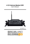
Vehicle 4-CH DVR System
USER MANUAL
3G Module
Without 3G Module
2013
Optional
AUG V1.4
Index
A.
Product Features ............................................................................................... 1
B.
Specification ...................................................................................................... 2
C.
Product Appearance ......................................................................................... 3
D.
Record / Stop-Record........................................................................................ 7
E.
System Operating Instruction ............................................................................ 8
1. Through IR Remote Controller Instruction ......................................................... 8
2. Through Carbox Player on PC Site ................................................................. 17
(1) Use CF card to playback directly ............................................................... 17
(2) 3G client software for viewing directly(select models with 3G modules)..... 23
F.
Format Memory Card ...................................................................................... 26
G.
Restoring Memory Card .................................................................................. 28
H.
Installation and setting up for 3G module ........................................................ 31
I.
Record Time Estimation (Based on constant record mode with 8GB card) ..... 37
i
A. Product Features
Max. up to 4 CH vehicle cameras, can take record for inside and
outside the vehicle.
Video output for live view, playback with monitor.
H.264 Compression format.
Recording format:D1 and CIF.
Build-in single channel microphone.
Quick Search Overall Event Log.
The full recording time and date can be showing in the monitor
directly.
Auto-Record after memory card Plug-in and Power Supplied.
Data Store in CF card for better safety and anti-vibration
performance.
4 sets of alarm input ports, built-in buzzer.
Support Record Video with audio, video, G-sensor and GPS data
at the same time.
Optional for 3G module, control the driving status and data at any
time.
1
B. Specification
Item
Video Format
Video Input
Audio Input
Video Output
Audio Output
Alarm Input
Alarm Output
Display Mode
Display Resolution
D1
Recording
Resolution
CIF
Recording Frame
Compression Format
Operation System
Triplex
Recording Mode
Schedule Recording
LED Indicator
Event Mode
Playback Mode
Network
GPS
Storage Type
Backup Device
Firmware Update
Multi-Language
G Sensor
Operation
Power Supply
Dimension
Weight
Operation Temperature
Accessories
Standard
Optional
Description
NTSC
PAL
4CH Input BNC/ Harness Connector
1CH Input / Harness Connector
1CH Output BNC / Harness Connector
1CH Output RCA / Harness Connector
4 Alarm Input
Buzzer
Full Screen, 4 Split
720 x 480
720 x 576
720 x 480
720 x 576
360 x 240
360 x 288
Max. 120 FPS
Max. 100 FPS
H.264 Technology
Embedded Linux Kernel
Record / Playback / Backup
Schedule Recording
15/30/60/120 Minutes
Power, Recording(CF1), GPS(CF2)
Alarm Trigger / Video Loss
Normal Speed x1/Fast Forward/Fast Rewind
Search Function: Time / Event
3G Module (optional)
GPS (optional)
CF Card
PC VIEWER
USB
English / Traditional Chinese / Others (Customizable)
G Sensor
IR Remote Controller (Extending IR Lead)
DC 8V~ 28V
214mm x 160mm x 58mm (W x D x H)
0.92kg ( including CF card)
-20°C~65°C (inside vehicle)
Main Machine, Remote Control, Card Reader,
3M Extending IR Lead, 3 Pin Power Cable,
Harness Plug for Video Input , Alarm Cable, Driver
CD, Quick Guide
★. Build-in 3G: Antenna, 1.5M Extension Antenna
Cord
3G Module, G-Mouse, SD Card
2
C. Product Appearance
Front Panel
Extending IR Lead
CF 1
CF 2
GPS Indicator LED(CF2)
IR Receiver
Record Indicator LED(CF1)
Power Indicator LED
Rear Panel
TYPE1: without 3G module
Video Input
Video Output
USB
GPS(optional)
Audio Output
Power Input
DC 8-28V
Harness Connector
Alarm Input
1. DC+12V output
2. Signal and general DC
3.
Video Output
Audio Input / Output
Harness Connector:
Assorted cable includes 4
set of image input, power
core and S connector.
3
4.
5.
6.
grounding
Signal and general DC
grounding
DC8~28V IN car power
input (positive electricity)
ACC starter control
GNDP car power
grounding(negative
electricity)
Wiring Diagram
A
B
C
A. Alarm input / Audio input/output
Alarm input
(Alarm trigger off signal +12~28V)
1. alarm input 1
2. alarm input 2
3. alarm input 3
4. alarm input 4
5. ground wire
Audio output/input
1. ground wire
2. Audio output
3. ground wire
4. Audio input
4
B. Harness Connector DC12V OUT / VIDEO IN
1.
2.
3.
4.
video input 1
video input 2
video input 3
video input 4
C. Power input/output
1. DC+12V output
2. Signal and general DC
grounding
3. Signal and general DC
grounding
4. DC8~28V IN car power input
(positive electricity)
5. ACC starter control
6. GNDP car power grounding
(negative electricity)
TYPE2: build-in 3G module
3G Module
TYPE3: with 3G USB dongle
5
3G USB Module
Dimension (UNIT: mm)
6
D.
Record / Stop-Record
Record Indicator LED(CF1)
Power Indicator
GPS Indicator LED(CF2)
1. Power on / Record
Turn on the power, and it will take approximately 40 seconds to
boot up. During the recorder booting up, the CF card indicator
LED will start flashing as the recording is in progress.
Light indicator:
● Red light: light on, means power on; light off, means no
power/power off.
● Yellow light: light flashing, means CF take recording; light off
means non-recording.
● Green light: light off means GPS not ready, light on means
GPS positioning ready.
★Remark: While using playback function in DVR, it cannot
take live recording at that time.
2. Power off/Stop recording:
Power off also stop recording, at then you can take out CF
card to read the recorded files.
Note
(1) Before using the memory disk, please format the disk first using the
software player in the CD-ROM. If not, device will automatically erase all
data in the memory disk before recording.
(2) All memory disks have limited lifespan. Please regularly watch videos on
PC and check the memory disk to ensure proper functioning.
7
E. System Operating Instruction
Vehicle DVR system provides two operational methods: IR remote
controller and PC software application.
1. Through IR Remote Controller Instruction
1.1 As following is the key mapping table for IR Remote controller:
CH2 display
CH1 display
Record
CH3 display
CH4 display
Quad display
Menu
Mute
Up、Down、Left、Right
Enter
Fast Forward
Fast Rewind
Stop
Play
Step/Pause
1.2 DVR OSD menu operation and IR remote controller key
mapping chart
Main menu page switch
page1/3 setting
page 2/3 setting
page3/3 (without 3G module)
page3/3 (with 3G module)
8
◆IR Remote controller Instruction
(1) Select Item: [up/down/left/right]
(2) Change setting for selected item: [up/down/left/right]
(3) Change setting for Bar item:[Enter]
(4) Full Screen display for each CH: [CH1~CH4]
(5) Open OSD menu, back to previous page:[menu]
(6) Quad display :[Quad]
(7) Enter playback mode :[play]
(8) Stop Play/exit playback mode:[Stop]
(9) Suspend recording:[Pause]
System Setup instruction
(1) Set Encode Parameter
IR Remote controller operating instruction
(1) Can be selected Resolution/Record frame rate /Recording
quality from up/down key on remote controller.
(2) Left key→ Change parameter.
(3) Right key→ Back to pervious parameter.
Items Setting
(1) Encode Frame Size (Res.): D1 / CIF
(2) Encode Frame Rate: 5/15/20/25/30
(D1 max. 15 / CIF max. 30)
(3) Encode Quality: Low/Normal/High
(2) Set Video Parameter
IR remote controller operating instruction
(1) Up/Down key→ Select current channel for setup
9
(2) Left/Right key→ Set brightness/contrast/hue for current
channel (Left key→ To reduce)/ (Right key→ To increase)
Item Setting
(1) Brightness: (Left key→ to reduce)/ (Right key→ to
increase)
(2) Contrast: (Left key→ to reduce)/ (Right key→ to increase)
(3) Hue: (Left key→ to reduce Hue)/ (Right key→ to increase
Hue)
(3) Set Time
IR Remote controller operating instruction
(1) Up key→ Plus one , Down key→ Reduce one.
(2) Left key→ Left one space, Right key→ Right one space.
(4) Set Plate Number
IR Remote controller operating instruction
(1) Up key→ Numbers plus one or alphabetical order to
increase.
(2) Down key→ Number reduce one or alphabetical order to
reduce
(3) Left key→ Left one space.
(4) Right key→ Right one space.
10
(5) Delete All Record Data (Format Disk)
(1) Delete All Record Data
Use right key or left key to select the selection then click
“enter” to confirm.
★Caution! All data will be deleted when you click “Yes”.
(6) Default Live View Channel Display
(1) Select the default live view CH after startup: Item selected
will be default live view display mode after DVR booting
completed.
(2) On this page, Use left key or right key to select Quad display
(Multi-CH) or CH 1 Display, then press “enter” to confirm.
(7) Power Management
(1) Power Management: Setup Extended Record period after
Engine shutdown.
(2) Use IR Remote controller for setting, Click Left key to move
one space for selecting time for delay-recording, then press
enter key to confirm.(The delay-recording period can be
0,5,10,15,20 minutes)
11
(8) Firmware Update
(1)
During firmware update, please do not power off; after
finished the DVR will reboot automatically.
(2) When update firmware, Using left/right button on remoter
controller to select Yes/No for update, then press enter
button to confirm.
★ Must use CF card for firmware update.
(9) Check Firmware Version
(1) To check current firmware version, please select version
and press enter key.
★ Check the current firmware version first before
firmware upgraded.
(10)
Check MDVR ID Information (Only available when DVR with
specific 3G module)
(1) If you need to check current MDVR ID information, please
click MDVR ID and press enter key on remote controller.
★Check the current MDVR ID version is the newest
version first before start 3G information setup.
12
(11)
3G Networking Setting (Only available when DVR with
specific 3G module)
(1) When enable the 3G networking function, Press the
right/left key on remote controller first to select 3G
ON/OFF, then press “confirm” key to save the change.
★ After setup finished, press the up/down key to check
information about 3G network settings are properly.
(12)
Alarm setup
(1) When the alarm is triggered, the screen should display
which CH is triggered. Press the right/left button on
remote controller to select channel, then press the
“confirm” key set the channel.
★Check the explanation of back panel, in order to
facilitate triggering alarm information setting.
13
★Alarm system works only after finishing both
hardware and software setting.
Ex. It could apply to switch CH to full
screen mode for driver when backward of
parking or using turn signals to prevent
blind corners.
1 CH
Input reverse signal
G
It could connect with
the second and third
black wire.(share
ground wire with
automobile)
★When the alarm is triggered, the screen switch to full display
which CH is triggered. And It will return to quad display when
alarm is finished.
Normal Statue
Alarm Mode
14
(13)
Password Setting (3G version without this function)
(1) Set password protected on machine: It required to enter
the password before setting, playback, formatting…
implement relevant actions.
(2) Use remote controller keys to change setting, Click Left key
to move one space for selecting number for password, then
click up/down key to enter the number, after finished, click
“enter” key to confirm. (You can select number 0~9 for the
password. If you don’t need the password function, please
enter a blank and click “enter” key to confirm.
★If the Player software does not set the playback
password; then when click “playback” button on the
remote controller, it will enter playback file directly of
the menu page
★When finished entering a password and move to next
password location, the former one will show a “ *
“symbol in order to protect password information.
15
LIVE Display
(1) Select CH1~CH4 to full display mode; If you want to return to
quad display, please press quad key.
(2) On Live view mode, click “menu’ to enter OSD menu or click
‘Play” to enter playback mode.
★ If it shows the “G” mark on Upper right screen, it means
GPS positioning successes.
Playback mode
Use remote controller to enter playback menu.
(1) Select CH1~CH4 as full display for each CH; If you want to
return to quad display, please press quad key.
(2) On Playback mode, please click “stop” to exit the playback
mode.
(3) Press pause key to pause video stream.
(4) On Pause mode, Press the play key to continue play
recording file.
(5) Press stop key on remote controller to exit playback screen.
16
2. Through Carbox Player on PC Site
(1) Use CF card to playback directly
from CD-ROM , the display as
Execute the CarBox2.exe
Play button to select memory card;
showing below. Click
to choose the files from memory card or
or click open file
hard disk, and then double-click the file you want to play.
play key will switch to
pause
Under playing mode the
key.
★Caution: It needs to install DirectX 9.0 or above before
running CarBox2 software.
Viewer Interface Schematic
GPS Coordinate
G SENSOR
Speed
Play BAR
Play speed
Volume
Control Interface
GOOGLE Map
★GPS Coordinate, Speed and Google Map (select models with 3G modules)
a.
Control Interface Description
17
1
2
3
4
5
6
7
8
9
10
11
12
13
14
Previous File
Previous Frame
Backward Play
Pause
Stop
Play
Next Frame
Next file
Open folder, select file.
Disk backup. Select the backup path for file
storage.
Google Map
Configuration
Snapshot
Tool, CF card format, language setting.
Hard Disk Backup
Review footage on the CF card through PC, Click” ”,
then it will pop-up as following backup dialogue windows.
18
Step 1. Select the CF card drive no.
Step 2. Select the recorded file which you want to backup
Step 3. Select the Backup Format
Backup format:
(1)Original CF card format backup.
XXXX*.sd file
(2)AVI File(*.avi) backup when take this format as backup.
CHN01 for front view camera image
file, file type: *.avi
★caution: The difference between original CF card
format file and AVI file is that AVI file contains only
video and audio data but lose the GPS coordinates,
speed and G-sensor data. As a result, we would
recommend to do the backup by original CF card
format.
Step 4. Backup Path: Select your backup destination.
(e.g.: C:\BlackBox)
19
Step 5. Backup: Click ‘backup’ to start saving the file to your
specified destination
Configuration
Before using the machine, please insert the CF card to
card reader and connect to the PC to start setting. After
setting, you can insert the card back to DVR and start
recording.
Video
Quality
Select the video Quality: High/
Normal / Low
2
Video
Frame
Set the recording frame rate for
the camera
(2、4、6、8、10、15、20、
25、30)
3
Video
Format
video signal format D1/CIF
1
4
You can input the driver’s name
or license number here to
identify people’s identity.
Suitable for company or group
using.
Car
Information
20
5
Audio
Recording
Audio recording on or off.
This function can encrypt the
data and prevent others from
accessing. Maximum
letters:15 letters.
Example: 123456789123456
6
After setting the password up,
you have to input password
every time for playing the files,
modify the setting, formatting
the memory card etc.
Password
★ Note: Please check if you
have set capital letters for your
password and save your
password well in other place to
prevent from missing.
You can set up the speed unit
here.
7
Speed unit
8
Time zone
Km/h: kilometer per hour
Mile/h: mile per hour
Knot: knot per hour
★ Note:1 KM=0.6214 mile,
1 mile=1.6093KM, 1 Knot
=1.853KM
Time Zone:
GMT (GPS auto time correction)
21
Snapshot
While playing the recorded file, you can use this function
to snapshot the picture and save it into your PC.
Default saving path for snapshot picture will be in
x:\IBoxPlayer/Snapshot folder.
File type: .bmp
b.
Latitude & Longitude Coordinates
Position
Latitude & Longitude
c.
G Sensor
G-sensor: Detect & record G-force data.
G SENSOR
(1) X: The G-force from left & right of the car.
(2) Y: The G-force from front & back of the car.
(3) Z: The G-force from upside & downside of the car
d.
Speed Meter
Speed
22
e.
Video Search & Play Speed
Video searching BAR
Play speed
(1) Video Searching: You can use the mouse to drag the bar
to search the video quickly.
(2) Play Speed: Support 2x, 4x fast forwarding and -2x, -4x
slow play mode.
f.
Volume Control
Volume BAR
Volume degree
Volume BAR: Click the left button of mouse control to
adjust the volume degree.
(2) 3G client software for viewing directly(select models with 3G
modules)
Executive Playback software “3G ClientApp.exe ”, the
playback screen shown as below. Enter the username and
” button to login
password and then press “
screen.
23
Note: To perform this software will require DirectX 9.0 or more.
Click
and then select the name of vehicle to view the image
(example, the figure of
175) then click on Channel-01 (or other
Channel) and then hold down the left mouse button and drag to the
split screen in right side.
The other method to choose split-screen first and then click on
Channel-01 with right key of the mouse, click PLAY function to view
real-time image. (When the icon becomes
, it means the vehicle
that is currently offline. Only the icon returns to online status
see the real-time image.)
to
★ Note: When play real-time image, Channel icon will become green
24
.
Click
records...
can watch the event log and vehicle driving
can watch the Google Map and inquiry the date and
Click
time record of the vehicle…..
25
3G ClientApp page and other relevant settings
1. Login: click Login on the top of the screen to open the login
screen information.
2. Add Device: In order to identify each device, add the vehicle
information here.
3. Style: watch different split-screen, just click Style option to set
values; Total 1 * 1, 2 * 2, 3 * 3, 4 * 4, 4 types of split screen to
choose.
F. Format Memory Card
When should you「format」the CF CARD?
When the used CF card or just a new card, you should format CF
card first before use. ( The CF Card with delivery has been
formatted and tested, you can just plug it in DVR).
█ The procedure to format the CF card:
1. Put CF card into the
reader slot and make sure
the direction is correct.
2. Insert the reader into the
USB Port on PC.
3. Execute the player “CarBox2.exe”
(refer to the charts below)
4. Select
into main page
format button to start as following steps
26
a.
b.
c.
d.
27
5. After formatting completed, re-insert the CF card to do
relative setting. please insert the card into DVR for
recording.
█Process to Format the CF Card on DVR:
1. Use remote controller to enter DVR menu and choose
Delete All the Record Data(format disk).
2. Select “Yes” and Click “Enter’’ to start formatting.
3. When the screen back to LIVE mode ,the formatting is
completed.
G. Restoring Memory Card
When should you「restore」 the CF CARD?
When the used CF card or just a new card, you should format CF
card first before use. ( The CF Card with delivery has been
formatted and tested, you can just plug it in DVR).
█ Formatting procedure from PC site:
1. Put CF card into the
reader slot and make sure
the direction is correct.
2. Insert the reader into the
USB Port on PC.
28
3. Execute the player “CarBox2.exe”
into main page(refer
to the charts below
)
4. Select restore button to start as following steps
a.
b.
c.
29
e.
d.
f.
5. You can use the memory card for other purposes.
30
H. Installation and setting up for 3G module
Please confirm 3G system with the telecom provider in local area,
and choose appropriate module to fit in with.
Telecommunication Norm:
WCDMA
3G Network Card:EM770W
Telecommunication Norm:
CMDA2000
3G Network Card: EM660
1. Installation Guide for 3G module
a. Take off two screws from front and back cases as red mark;
please remove upper cover from this device.
31
Installation interface for SIM card
and 3G module.
32
b. Installation process for EM770W of HUAWEI 3G Module (SIM
card shell be purchased by customer)
i. Disable PIN code from SIM card by mobile phone firstly and insert this
card into the device.
1. Insert SIM card into the slot
2. Flat the SIM card and push
into the buttom then locked
ii. Start to install of 3G module after SIM card installation.
1. Slanting insert the 3G module
into PCI-E slot.
2. Push the 3G mould on flat
status and lock two pieces of M2
screws.
3. Connect antenna to “M”
Position of the module
4. Complete installation of
antenna and module
EM660 module
33
2. 3G INTERNET SETTING
a. Please confirm whether the code number is closed or not.
b. Confirm if The Telecommunication providers’ APN is the same
with Dial-Up Number’s information, if not, please follow all 3G
Config Tool setting file steps.
and open the setting
i. Please double click
page as below:
The explanation for setting up:
1. UserName: No need in common
2. Password: No need in common
3. Server Address: Enter Server IP address setting----Default
34
4.
5.
6.
7.
Server IP Address is 61.221.66.200
Server Port: Default Sever Port is 13579, Not recommend to
change the original setting).
APN: 3G APN, generally preset to be Taiwan
Telecommunication providers, if in other area, Please check
local Telecommunication providers offered APN setting name.)
Dial-Up Number: 3G Dial-Up Number, generally preset to be
*99#, if in other area, Please check local Telecommunication
providers offered 3G Dial-Up SETTING Numbers.
3G On/Off: To choice whether star the 3G tele-connecting
function or not. “Pick” (V) mean “Star” commonly, if not willing
to use tele-connecting function , please directly neglect it.
ii. Please put USB FLASH DRIVER into the PC’s USB drive port,
choice & click the proper disk storage. And input the following
data as below:
iii. After inputting, pick <o.k.> and process saving, the 3G Module
information setting would be finished at this moment. Please
check the USB Flash Driver DISK to find out if our
<net3g.ncf>file existed .
35
iv. And Please put your USB FLASH DRIVER into the SA-650-CF
USB connecting Port, and re-connect the battery again.<After
first {star}, if update information successfully, It would re-start
again after 10 seconds.>
v. After re-start, please pick the 3G internet item up in contents to
confirm whether the 3G information updating successful or not.
When updating successfully, all the updating information would shown
on the 3G module related web information.
When 3G connecting successfully,
the right upper screen would show N
signal.
36
I.
Record Time Estimation (Based on constant
record mode with 8GB card)
*The chart of estimated record time listed below is for reference only(based
on 8Gb with 2 inner &2 exterior Cameras). The length of time recorded can be
varied due to different record condition.
Unit: Hr
Resolution/
fps
Video Quality
High
Normal
Low
D1
CIF
5 fps
10 fps
15 fps
5 fps
10 fps
15 fps
20 fps
25 fps
30 fps
9.5
4.2
3.1
15
13.3
8.5
8
7.5
7
12
6.7
6.3
18
14.3
9
8.3
8.1
7.5
16.8
7.2
12
20
17.8
14.3
11.2
9.7
9.2
37