1
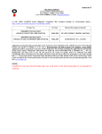
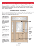
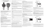
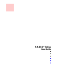
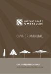
INSTALLATION AND OPERATING INSTRUCTIONS YD30 COBALT CONTENTS 1. DESCRIPTION Pg. 2 2. PRODUCT UNBOXED Pg. 2 3. DIMENSIONS 3.1. Lock 3.2. Strike Plate 3.3. Fitting Tab 3.4. Housing 3.5. Dress Plate Pg. 3 3 3 3 3 3 4. PRE - INSTALLATION ASSESMENT o 4.1. Mechanical o 4.2. Electrical Pg. 4 4 4 5. INSTALLATION 5.1. Mortise Installation 5.2. Surface installation Pg. 4 4 6 6.1. Fail Safe connection 6.2. Fail Secure connection 6.3. Jumper position Pg. 8 8 8 9 7.1. Fail Safe Operation 7.2. Fail Secure Operation Pg. 9 9 9 o o o o o o o 6. WIRING o o o 7. OPERATION o o 8. SPECIFICATIONS Pg. 10 9. MAINTENANCE Pg. 10 10. WARRANTY Pg. 10 11. UPGRADE Pg. 10 © BQT Solutions (SEA) Pte Limited Page 1 1. DESCRIPTION The COBALT is a motor driven low voltage electric lock designed to secure commercial and residential swing through doors. It is supplied with a matching strike plate and can be surface mounted with the aid of available accessories, or installed into a mortise for a concealed solution. The lock has been designed to address the two biggest issues in concealed electric locking today; 1. The ability to ‘pull’ a door into alignment even if the door has not closed in a central position. 2. The ability to release when requested even if there is excessive load on the door. The design of the COBALT is unique as it has two motors which independently operate two locking pins. These dual bolt pins offer extra strength but more importantly ensure the door can be secured even when the door has not closed in the correct position. This is achieved by the lock sensing which direction the door is closing from and activating the appropriate bolt pin to ‘grab’ the door and pull it into alignment before the other bolt pin activates. A door that is 8mm off alignment in either direction (16mm total window) will be secured with the COBALT. With the door secured and locked the COBALT can be given an unlock signal and it will instantly unlock. If the door is loaded (pre-load) when the unlock signal is given the COBALT will still unlock, even with loads in excess of 100Kg on the door. Critically the ability of the COBALT to instantly release with excessive pre-load on the door even occurs in the event of a power failure if the lock is configured as fail safe. Additional features of the COBALT are; Multi-voltage input (12-24VDC) Very low current consumption Door position and Bolt position monitors High physical strength – 10,000N holding force Fail safe / fail secure on site conversion with the re-positioning of a single jumper 2. PRODUCT UNBOXED Along with the COBALT and matching strike there are also 10G Self Tapping and M5 Machine Screws supplied. Four fitting tabs are also enclosed and can be used in conjunction with the M5 screws for recessing the lock or strike plate to metal doors and frames. The 7 way wire loom supplied is used to ease installation as the wiring can be done without the lock being installed until the very end. Wire Loom Mounting Screws Fitting Tabs Strike Plate © BQT Solutions (SEA) Pte Limited Lock Page 2 3. DIMENSIONS 3.1 Lock 3.2 Strike Plate 3.3 Fitting Tab 3.4 Housing - Available separately 3.5 Dress Plate - Available separately © BQT Solutions (SEA) Pte Limited Page 3 4. PRE - INSTALLATION ASSESMENT 4.1 Mechanical The first decision regarding installation is whether the COBALT will be mortised or surface mounted to the door / door frame. Mortise installation ensures a discrete solution as the lock and strike plate can be embedded into the door and frame, however in some instances this is not possible. Glass doors for example require surface mounting which is done with the aid of the YD30 housing. Whichever method is chosen it is important that the lock and strike plate are aligned correctly. The strike plate has two openings to accept the dual bolt pins and centring these openings with the bolt pins will ensure correct operation. The COBALT can be installed vertically or horizontally but is not designed to be mounted in a floor cavity firing upwards or in a wet environment. 4.2 Electrical The first consideration is to establish where to run the wires and decide on what feedback is required from the lock. There are a total of seven available connections; three are compulsory power connections whilst the remaining four provide optional door and bolt position feedback. These optional connections can be integrated into access control or alarm systems to provide full monitoring. The correct gauge of wire needs to be chosen as voltage drop across the power wires (+ and -) can limit the locks operation. For all the remaining connections, a lower gauge wire can be used as these are only signal wires. The following chart shows the maximum distance that the power supply can be away from the lock, assuming the power supplies output 12VDC or 24VDC: AWG AREA (mm2) 24 MAXIMUM DISTANCE (m) 12VDC 24VDC 0.20 7 20 22 0.33 11 32 20 0.52 17 51 18 0.82 27 82 16 1.31 43 130 14 2.08 69 206 5. INSTALLATION Two installation examples are detailed on the following pages; mortise and surface, however any combination of the two can be achieved. Whichever installation method is chosen it is vital to ensure that the lock face plate and the strike plate align correctly and the gap between the lock face plate and strike plate does not exceed 8mm when the door is closed. 5.1 Mortise Installation A typical mortise installation is described on the flowing page, with the lock fitted into the door frame and the strike plate secured into the door. It is possible to install the lock into the door and the strike plate into the frame however with this method running wiring to the lock requires additional work. © BQT Solutions (SEA) Pte Limited Page 4 5.1.1 Cutting the mortises Cut-out in a wooden door frame to accommodate the lock. Referring to the dimension drawings in Section 3; mortises are cut into the door and door frame suitable to fit the strike plate and lock. Wooden doors and frames require full mortises where metal doors and frames, being hollow, often only require a single rectangle cut-out to accommodate the lock face plate or strike plate. For these installations the supplied fitting tabs can be used to secure the lock and strike plate in place. The mortise behind the lock body needs to have enough space to accommodate the wire connections. Cut-out in a metal door to accommodate the strike plate. 5.1.2 Wiring the lock Wires are run from the power supply to the lock. A hole needs to be drilled in the back of the mortise to bring the wires out and a connection can be made to the supplied wire loom which in turn plugs into the lock. The jumper needs to be positioned for fail safe / fail secure configuration as per the instructions on the lock cover. The Red, Black and Blue wires are essential connections whilst the Violet and White are optional. Detailed wiring instructions can be found in Section 6. 5.1.3 Fitting the lock and strike plate The lock is slid back into the mortise, making sure that the wiring integrity is maintained and secure in place with the supplied 10G self tapping screws. Strike plate installed in the door using the fitting tabs. Before the strike plate is installed the fitting tabs are secured in behind the cut-out using the supplied M5 machine screws. The strike plate is then placed into the cut out and the remaining M5 screws are used to secure it. Lock secured directly into the door frame. © BQT Solutions (SEA) Pte Limited Page 5 5.1.4 Checking the operation With the lock and strike installed and wiring complete the door is closed to check the alignment and operation. The key area for alignment is the bolt pins; the pins are designed to touch the leading edge of the strike plate hole to pull the door in, but they cannot be allowed to touch the sides of the hole as this will limit their unlocking ability. If they rub or touch the side of the strike plate hole, either the lock or strike plate needs to be re-positioned. Clearance Bolt pin Clearance The bolt pin touches the leading edge of the strike plate hole but there needs to be clearance around the sides of the hole. 5.2 Surface Installation By using a YD30 housing, the lock and or strike plate can be surface mounted to the door or door frame eliminating the need for cutting mortises. Housings are available with adhesive tape supplied for easy application to glass doors in addition to having screw hole mounting points for wood and metal doors. 5.2.1 Securing the lock housing to wood Before fitting the housing, determine exactly where the wiring will enter the housing and drill one or two 8mm holes through the housing wall. Ensure the holes are on the housing face that goes against the wooden frame. Push the supplied grommet(s) into the drilled hole(s). The two 10G Hex head self-tapping screws supplied with the housing can then be screwed into the wood but not tightened. The two keyhole shaped cut outs in the housing fit over these screw heads which are tightened with a ring spanner once the housing is in place. 5.2.2 Wiring the lock Wires are run from the power supply to the lock through the drilled hole(s) in the housing. A connection can be made to the supplied wire loom which in turn plugs into the lock. The jumper needs to be positioned for fail safe / fail secure configuration as per the instructions on the lock cover. The Red, Black and Blue wires are essential connections whilst the Violet and White are optional. Detailed wiring instructions can be found in Section 6. © BQT Solutions (SEA) Pte Limited Page 6 5.2.3 Fitting the lock into the housing Once wired, the lock is slid into the housing and secured in place with the supplied M5 machine screws. Make sure that the wiring integrity is maintained as the lock is screwed in place. 5.2.4 Fitting the strike plate housing to glass For simple application to glass the YD30 housing is supplied with self-adhesive tape. With the backing removed the housing can be applied directly to the glass. A flat stainless steel dress plate is fitted on the opposite side of the glass to give a clean finish. The protective coating on the dress plate can be removed once it is in place. 5.2.5 Fitting the strike plate into the housing The strike plate is placed into the housing and secured in place with the supplied M5 machine screws. 5.2.6 Checking the operation With the lock and strike installed and wiring complete the door is closed to check the alignment and operation. The key area for alignment is the bolt pins; the pins are designed to touch the leading edge of the strike plate hole to pull the door in, but they cannot be allowed to touch the sides of the hole as this will limit the unlocking ability. If they rub or touch the side of the strike plate hole, either the lock or strike plate needs to be re-positioned © BQT Solutions (SEA) Pte Limited Page 7 6. WIRING The COBALT is supplied with a 7-way wire loom that plugs directly into the lock. The wires are colour coded with three being essential connections and four optional. Control of the lock is achieved by using the three power wires, whilst door and bolt position monitoring are available when desired. Connect the COBALT as per the chart: RED POS Positive connection to DC power supply (12–24V) BLACK NEG Negative connection to DC power supply (12–24V) BLUE CTRL Switched positive control input VIOLET VIOLET NO Contacts closed when bolt pins are extended, and contacts open when bolt pins are retracted Bolt Position Switch WHITE WHITE NO Contacts closed when door is aligned, and contacts open when door is open Door Position Switch COM COM Power 6.1 Fail Safe Connection When wiring the COBALT, the positive voltage is connected to RED, negative is connected to BLACK and a switched positive voltage wire connected to BLUE. In Fail Safe configuration applying voltage to the COBALT signals it to lock. The lock signal in Fail Safe configuration is active high. Wire loom from lock WHITE WHITE VIOLET VIOLET BLUE Door Position Switch Bolt Position Switch NC - Unlocked NO - Locked BLACK - RED + DC Power Supply 6.2 Fail Secure Connection When wiring the COBALT, the positive voltage is connected to RED, negative is connected to BLACK and a switched positive voltage wire connected to BLUE. In Fail Secure configuration applying voltage to the COBALT signals it to unlock. The lock signal in Fail Secure configuration is active low. Wire loom from lock WHITE WHITE Door Position Switch VIOLET VIOLET Bolt Position Switch BLUE © BQT Solutions (SEA) Pte Limited NO - Locked NC - Unlocked BLACK - RED + DC Power Supply Page 8 6.3 Jumper position The fail mode of the COBALT is factory set as Fail Safe, i.e. in the event of a power cut the COBALT will unlock. Before the lock is installed this can be changed to Fail Secure by repositioning the jumper located next to the 7-way plug on the end of the lock. Select the desired jumper location as indicated: Jumper in Fail Safe position. Jumper in Fail Secure position. Fail Safe = Fail Unlocked = Power To Lock = PTL Fail Secure = Fail Locked = Power To Open = PTO 7. OPERATION 7.1 Fail Safe Operation Assume the lock is installed and wired, the door is open and there is voltage applied to the BLUE wire. As the door closes the COBALT senses the door approaching and activates the appropriate bolt pin to pull the door into centre alignment. Once the first bolt pin has fully extended, the second bolt pin activates and drives to its full extension. If the door closes to a centre aligned position quickly then both bolt pins activate at the same time rather than one leading the other. The Bolt Position and Door Position monitors will have changed state as the door is moved into place and secured. To unlock the door, voltage is removed from the BLUE wire. The COBALT will immediately release and will do so even when significant load is being applied to the door. With the door now open the Bolt Position and Door Position monitors change state again. The COBALT will remain unlocked as long as the door is open but will instantly relock when voltage is applied to the BLUE wire and the door is closed. In the event of a power failure, voltage is removed from the BLUE wire and the COBALT unlocks. 7.2 Fail Secure Operation Assume the lock is installed and wired, the door is open and voltage is removed from the BLUE wire. As the door closes the COBALT senses the door approaching and activates the appropriate bolt pin to pull the door into centre alignment. Once the first bolt pin has fully extended, the second bolt pin activates and drives to its full extension. If the door closes to a centre aligned position quickly then both bolt pins activate at the same time rather than one leading the other. The Bolt Position and Door Position monitors will have changed state as the door is moved into place and secured. To unlock the door, voltage is applied to the BLUE wire. The COBALT will immediately release and will do so even when significant load is being applied to the door. With the door now open the Bolt Position and Door Position monitors change state again. The COBALT will remain unlocked as long as the door is open but will instantly relock when voltage is removed from the BLUE wire and the door is closed. In the event of a power failure, voltage is removed from the BLUE wire and the COBALT locks if the door is closed. © BQT Solutions (SEA) Pte Limited Page 9 8. SPECIFICATIONS MATERIALS Bolt Pins SS17-4PH, 10mm Thick, 13mm extension (2 Pieces) Strike Plate SS304, 3mm Thick Lock Face Plate SS304, 3mm Thick MECHANICAL Cycle life > 300,000 Strike Gap < 7mm Holding Force > 10,000N (1000kg) Side Load Release > 1,000N (100kg) Door Misalignment +/- 8mm ELECTRICAL Voltage at Lock Current Usage Monitor Switches 12 – 24VDC ±15% Holding Current < 50mA@12V < 30mA@24V Operating Current < 250mA@12V < 200mA@24V Initial Power Up* < 1800mA@12V < 600mA@24V Bolt position – 30VDC, 0.1A Door position – 100VDC, 0.5A CERTIFICATIONS Patent Pending PCT/IB2013/053737 FCC Part 15 Subparts A & B – Unintentional Radiators CE EN 61000-6-1: 2007, EMC Directive 2001/108/EC Immunity EN 61000-6-3: 2007, EMC Directive 2001/108/EC Emissions * Initial power up of the lock requires up to 1800mA@12VDC and up to 600mA@24VDC for up to 6 seconds but only occurs when the power has been completely removed for an extended period then re-applied, for example after a power outage. Normal Operating Current after initial power up is <250mA@12VDC and <200mA@24VDC. 9. MAINTENANCE The COBALT has been lubricated at assembly and applying any other type of lubricant may void the warranty. Removing the lock cover may void the warranty. A dry cloth can be used to polish the stainless steel face plate and strike plate as required. 10. WARRANTY The COBALT is covered with a manufacturers 12month warranty against faulty or malfunctioning parts, components or product. At the manufacturer’s discretion, either a replacement lock or affected part will be supplied to remedy the fault or the lock can be returned at the customer’s expense to the manufacturer for repair. Mistreatment or ill-use of the lock may void the warranty. COBALT is a trademark of BQT Solutions (SEA) Pte Limited. BQT Solutions (SEA) Pte Limited will not be liable for any direct, indirect, incidental or consequential loss or damage in any way related to this product. 11. UPGRADE The COBALT is designed by BQT Solutions (SEA) Pte Limited and manufactured by BQT Solutions (NZ) Limited. BQT Solutions (SEA) Pte Limited reserves the right to upgrade or change this product without prior notice. For more information visit www.bqtsolutions.com © BQT Solutions (SEA) Pte Limited Page 10 NOTES © BQT Solutions (SEA) Pte Limited Version 3.0 Page 11