1
LizardTech®
GeoViewer 5
User Manual
Copyrights
Copyright © 2009–2010 LizardTech. All rights reserved. Information in this document is subject to
change without notice. The software described in this document is furnished under a license agreement or nondisclosure agreement. The software may be used or copied only in accordance with the
terms of those agreements. No part of this publication may be reproduced, stored in a retrieval system, or transmitted in any form or any means electronic or mechanical, including photocopying and
recording for any purpose other than the purchaser's personal use without the written permission of
LizardTech.
LizardTech acknowledges and thanks the many individuals and organizations whose efforts have
made our products possible. A full list of copyright, trademark and credit information is available in the
document "Copyrights, Trademarks and Credits" installed automatically with your product.
LizardTech
1008 Western Avenue, Suite 200
Seattle, Washington, USA 98104
206.652.5211
www.lizardtech.com
Table of Contents
Chapter 1: Introduction
1
System Requirements
1
A Note about Terminology
1
Chapter 2: Installing or Updating GeoViewer
3
Chapter 3: Getting Oriented in GeoViewer
7
The Overview Pane
7
The Menu Bar
8
The Toolbar
10
The Map Pane
11
The Project Pane
12
The Status Bar
12
Context Menus
12
Chapter 4: Viewing Maps and Layers
15
Adding a Layer to View
15
Hiding and Showing Layers
17
Panning
18
Zooming In and Out
19
3D Viewing
20
Restoring Original View
23
Customizing GeoViewer's Background Color
23
Selecting and Deselecting Layers
24
Selecting Bands
24
Viewing Layer Metadata
25
Chapter 5: Working with Coordinate Reference Systems
27
Setting the CRS for a Map
27
Reconciling Projections Among Layers
27
Chapter 6: Working with Projects
29
Creating a New Project
29
Opening an Existing Project
29
Organizing Layers
29
Removing a Layer from a Project
30
Viewing and Setting Layer Transparency Values
31
Saving a Project
33
Chapter 7: Measuring Distance
Using the Measure Tool
35
35
- iii -
Setting Measurement Units
37
Chapter 8: Exporting Maps and Layers
39
Chapter 9: Preferences
41
Setting Georeferencing Preferences
41
Setting User Interface Preferences
41
Setting GeoViewer Update Preferences
43
Appendix A: Technical Information
45
Supported File Formats
45
Viewing System Information
46
Appendix B: Product and Company Information
Displaying Tips and Tricks
47
Displaying the GeoViewer About Box
47
About LizardTech
48
Other LizardTech Products
48
GeoViewer and Patents
49
Index
- iv -
47
51
Chapter 1:
Introduction
Thank you for using LizardTech® GeoViewer 5. We’re confident that you will find GeoViewer to be
everything you need to view and export maps employing high resolution images and image mosaics.
Whether you're viewing imagery on your computer's hard drive, on a WMS or JPIP server, or in a
LizardTech Express Server® catalog, GeoViewer makes rapid viewing of large images possible while
maintaining maximum image quality.
GeoViewer now supports importing files of the MrSID® Generation 4 (MG4) format as layers. MG4
support means you can specify any three bands of a multispectral file to view as the red, green and
blue bands, or any single band to view as the grey band. The "Select bands" dialog can be reached by
right-clicking a layer's name in the project pane (see "Selecting Bands" on page 24).
The purpose of this user manual is to give you quick information about how to use GeoViewer to view
image, vector and LiDAR data. To access this documentation as WebHelp within the application,
select Help Topics from the Help menu.
If you have not yet installed GeoViewer or need to update the application, see "Chapter 2: Installing or
Updating GeoViewer" on page 3. For a quick visual overview of the user interface, see "Chapter 3:
Getting Oriented in GeoViewer" on page 7. The most common navigational tasks are covered in
"Chapter 4: Viewing Maps and Layers" starting on page 15. Saving projects and other procedures are
covered in other chapters.
System Requirements
The following system is recommended for installing and running GeoViewer:
l
l
l
l
l
One of the following operating systems:
o Microsoft Windows XP, 32-bit, Service Pack 3
o Microsoft Windows XP, 64-bit, Service Pack 2
o Microsoft Windows Windows Server 2003, Service Pack 2
o Microsoft Windows Vista, Service Pack 1
o Microsoft Windows 7
Microsoft .NET Framework 4.0 (included)
Microsoft DirectX 9.0c
1-GHz processor
2 gigabytes (GB) RAM
NOTE: In order to use GeoViewer's 3D viewing tab, your system must be running Microsoft DirectX
9.0c. You must visit Microsoft's website (http://msdn.microsoft.com/en-us/directx/aa937788.aspx)
to download DirectX. You can still use GeoViewer's 2D viewing tab without DirectX.
GeoViewer comes in both 32-bit and 64-bit versions. Yes, you may run the 32-bit version on a 64-bit
system if you wish.
A Note about Terminology
If you are familiar with GeoExpress and other LizardTech products designed specifically and exclusively for work with raster images and mosaics, you're probably used to calling things added to
-1-
LizardTech GeoViewer 5 User Manual
project lists "images" or "mosaics", or even "tiles".
Because LizardTech GeoViewer is designed for viewing and exporting GIS layers that may include
other kinds of data besides raster imagery (such as vector and LiDAR data), this vocabulary no longer
covers all the possibilities. GeoViewer therefore introduces some new terminology.
Map – What you see in the large main window is called a "map". A map is the total of all
raster and vector images and LiDAR data added together. That large window is called
the Map pane. Even if all you're doing is viewing a mosaicked raster image with no vector or LiDAR data, GeoViewer still considers you to be viewing a map.
Layer – The images and other data that you add to the map are called "layers". Whether
you want to import an image, a single tile of a mosaic, a LiDAR file, or a vector overlay,
you import it as a layer. Layers can be displayed or hidden.
NOTE: When a project consists of a single layer, that layer is identical to the map.
The GeoViewer user interface exclusively employs the "map and layer" terminology. The GeoViewer
help materials may use both "layer" and "image" depending on context.
Now, off you go. We hope that this little chat will have made it easier for you to get started using GeoViewer.
-2-
Chapter 2:
Installing or Updating GeoViewer
GeoViewer uses an easy installation mechanism. Simply go to LizardTech's downloads page and
select your operating system to download and install the latest version of GeoViewer.
NOTE: Administrative privileges are not required to install GeoViewer, but they are required to
install any prerequisite software, such as Microsoft .NET Framework.
To install or update GeoViewer:
1. Point your browser to:
http://www.lizardtech.com/downloads/viewers.php
2. Click GeoViewer 5.
3. Click Windows - 32 bit or Windows - 64 bit under GeoViewer 5.
4. Read the license agreement and click I Agree to begin installation.
The installation process automatically checks your computer to make sure your version of Windows
has the prerequisite software (Note: DirectX is an exception. You must download DirectX from Microsoft's website).
If prerequisite software is missing and you have administrative privileges, you may be prompted for
administrative credentials and the software is automatically downloaded and installed.
If you do not have administrative privileges, see your IT administrator for help downloading and installing the software.
Once all the prerequisite software is installed, the installation process installs and runs GeoViewer.
NOTE: When using Firefox to access the download page you may have to save the executable
(setup.exe) and then run it locally.
Checking for Updates
You can check for newer versions of GeoViewer anytime, or you can set GeoViewer to automatically
remind you to check for updates. You can even specify how often it should prompt you. By default
GeoViewer reminds you every 7 days to check for a new version.
To manually check for updates:
1. Choose Check for updates from the Help menu. The Check for Updates dialog appears as
shown below with information about your current version and the date and time you last
checked, and the latest version (Note: the Latest Version field is blank until you have checked
for updates).
-3-
LizardTech GeoViewer 5 User Manual
2. Click Check for updates. If a more recent version of GeoViewer is available it is listed as the
"latest version" and the button changes to say "Download". If not, the button becomes unavailable.
3. Click Download if you wish to update GeoViewer. The new version is downloaded and
installed, as shown below.
4. Close and restart GeoViewer.
After you restart, you will be running the new version of GeoViewer. You can confirm this by again
choosing Help > Check for updates.
For information on setting automatic updates, see "Setting GeoViewer Update Preferences" on page
43.
Uninstalling GeoViewer
To uninstall GeoViewer:
1. Open your Control Panel and choose Add/Remove Programs (Programs and Features on
Vista). The Add/Remove Programs dialog (or equivalent Vista task pane) appears.
2. Choose an option and click OK.
-4-
Chapter 2: Installing or Updating GeoViewer
Restore the application to its previous state leaves the application installed but removes the most
recent update. This option is only available if you have already installed a previous version.
Remove the application from this computer completely removes the application.
-5-
Chapter 3:
Getting Oriented in GeoViewer
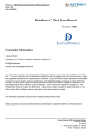
GeoViewer's user interface is shown in the illustration below with its basic components labeled. Brief
descriptions of these components are given further below. They are discussed in more detail on their
respective pages.
GeoViewer's User Interface
The Overview Pane
The Overview pane occupies the upper left corner of the user interface. It displays a fixed overview of
the map (see "A Note about Terminology" on page 1). At zoomed-in views, a navigation rectangle
inside the Overview pane delineates the region that is in view in the Map pane.
-7-
LizardTech GeoViewer 5 User Manual
As you pan the image in the Map pane, the navigation rectangle moves in the Overview pane to
reflect the panning motion, so that the rectangle always represents the current Map pane view. You
can use the Overview pane to pan; simply move the navigation rectangle (click and hold, then drag) to
recenter the view showing in the Map pane.
By default, the navigation rectangle is red and has a width of three pixels. You can change these attributes in your UI preferences (see "Setting User Interface Preferences" on page 41).
For more information, see "Chapter 4: Viewing Maps and Layers" on page 15.
The Menu Bar
The Menu bar offers commands and options on six menus and their submenus, as described in the
table below.
The Menu Bar
Menu
Item or Submenu
Description
File
Add layer
Local layer... – Enables you to specify or browse directories
for one or more images, mosaic tiles, or vector or LiDAR files.
Express Server Layer... – Enables you to specify and connect
to an Express Server, browse catalogs, and choose imagery.
WMS layer... – Enables you to specify and connect to a
WMS server, select layers, and specify format and EPSG
code.
JPIP layer... – Enables you to specify a WMS server and
select an image for viewing via the JPIP protocol.
Layer
-8-
Add group...
Creates a folder in the Project pane for grouping layers. You
can name each layer group as it is created.
Recent layers
Enables you to browse for recently opened layers. Unavailable
("grayed out") until after first layer is added.
Load project...
Enables you to specify or browse directories for an existing
project.
Recent projects
Enables you to browse for recently opened projects. Unavailable until after first project is saved.
Close project
Closes the current project and opens a new, untitled one.
Save project
Saves changes you have made to the current project.
Save project as...
Enables you to specify a name and location for saving a
project.
Exit
Quits the GeoViewer application.
Remove selected
Removes a layer or layers from the Project pane.
Chapter 3: Getting Oriented in GeoViewer
Menu
Item or Submenu
Description
Remove all
Removes all groups and layers.
Hide/show selected
Makes layers appear in or disappear from Map pane.
Rename...
Enables you to rename a group or layer.
View layer metadata
Displays metadata about selected layers.
Set layer transparency... Enables you to specify which color should be transparent for a
layer.
Navigation
Tools
Vector settings...
Enables you to specify width and color for vector lines for a
layer.
Home
Restores original view.
Pan
Sets cursor to panning mode.
Zoom In
Sets cursor to zoom in mode.
Zoom Out
Sets cursor to zoom out mode.
Smooth Zoom
Sets cursor to Smooth Zoom mode.
Orbit focal point
(3D mode only) Moves your viewpoint in an orbit around your
focal point. Disabled in 2D viewing.
Refresh points
(3D mode only) Freshly displays a configurable number of
points that fall within the current view. Disabled in 2D viewing.
Zoom to layer(s)
Zooms to selected layer(s).
Measure
(2D mode only) Sets cursor to Measure mode and displays the
Measurement pane.
Clear measurements
(2D mode only) Removes measurement lines and clears all
reported segment lengths.
View layer metadata
Displays metadata about selected layers.
Export
Export current view... – (2D mode only) Creates a file of
exactly what you see in the Map pane, including vector overlays.
Export map... – (2D mode only) Creates a file showing the
region covered by all layers, regardless of whether those layers
are hidden or shown.
Options
Georeferencing preferences
Enables you to choose warning options and specify how georeferencing information should be treated when layers are
added to a map.
-9-
LizardTech GeoViewer 5 User Manual
Menu
Item or Submenu
Description
UI preferences
Enables you to set preferences for the GeoViewer user interface.
AutoUpdate preferences Enables you to specify whether and how often you want GeoViewer to check automatically for updated versions.
Help
Help topics
Opens GeoViewer WebHelp.
Tips and tricks
Displays the Tips and Tricks dialog.
GeoViewer support
Links to http://www.lizardtech.com/support/geoviewer
Check for updates...
Enables you to check for and download the latest version of
GeoViewer.
System information
Provides details pertaining to your installation of GeoViewer.
About GeoViewer
Displays version number and copyright information.
The Toolbar
The GeoViewer toolbar is located above the Map pane and offers tool buttons identified by the following icons:
Toolbar icons
- 10 -
Home
Restores the original view, centered and scaled for best fit (see "Restoring
Original View" on page 23). In 3D viewing, repositions your viewpoint to its
original position zoomed out along your z axis.
Pan
Enables you to move the view in any direction within the layer (see "Panning" on page 18). In 3D viewing, "moves" the data from side to side or up
and down.
Zoom In
The Zoom In tool can be used to click in to a selected area by increments or
to define a precise region of the image to zoom in on (see "Using the Zoom
In and Zoom Out Tools" on page 19).
Zoom Out
The Zoom Out tool is used to incrementally view a greater portion of the
image than the current view, and incidentally to change the view's centerpoint (see "Using the Zoom In and Zoom Out Tools" on page 19).
Smooth
Zoom
The Smooth Zoom tool enables you to zoom in or out in a continuous motion
(see "Using the Smooth Zoom Tool" on page 20).
Orbit Focal
Point
(3D mode only) Moves your viewpoint in an orbit around your focal point. Disabled in 2D viewing.
Refresh
Points
(3D mode only) Freshly displays a configurable number of points that fall
within the current view. Disabled in 2D viewing.
Chapter 3: Getting Oriented in GeoViewer
Measure
The Measure tool enables you to measure distance between points (see
"Chapter 7: Measuring Distance" on page 35).
Tips and
Tricks
Clicking the GeoViewer logo on the toolbar displays the Tips and Tricks
dialog (see "Displaying Tips and Tricks" on page 47).
The toolbar also offers a Zoom slider, shown below, for zooming in or out by increments (see "Using
the Slider Bar" on page 19).
TIP: If you resize your main window to smaller dimensions, some of the tools may disappear from
the toolbar, starting on the right. These tools can still be quickly accessed using the More Buttons
drop-down. In the illustration below, several buttons and the Zoom slider have been removed to the
More Buttons drop-down.
The Map Pane
The Map pane is the large pane occupying the right side of the user interface. This is where you view
detail in maps and layers and mark points for measurement.
The Map pane displays the map at the zoom level you select and centered according to whatever panning movements you perform.
As you navigate within the map (zoom in, pan, etc.), the view in the Map pane changes accordingly.
- 11 -
LizardTech GeoViewer 5 User Manual
The Map pane has two tabs, one for two-dimensional (2D) viewing and one for three-dimensional (3D)
viewing. Select the tabs at the bottom left corner of the Map pane.
For more information, see "Chapter 4: Viewing Maps and Layers" on page 15.
The Project Pane
When you open a layer (see "A Note about Terminology" on page 1) a temporary project file is
created, even if you only view a single layer and then close it. The Project pane enables you to add
layers to your map and turn each layer on or off for creating and exporting different views. For more
information see "Chapter 6: Working with Projects" on page 29.
The Status Bar
Located at the bottom of the user interface, the status bar reports the map's coordinate reference system, whether GeoViewer is idle or working, and the position of your cursor as it moves across the
Map pane (2D mode) or the x and y coordinates of your focal point (3D mode). Cursor position is
reported in any or all of the following georeferencing modes.
l
l
l
l
Latitude/Longitude
MGRS - (Military Grid Referencing System)
Native - (the CRS of your map, determined when the first layer was added)
Pixels
By default, GeoViewer reports positions in Latitude/Longitude and Native. You can change this and
other status bar options in your UI preferences (see "Setting User Interface Preferences" on page 41).
Context Menus
A context menu (sometimes called a “right-click” or “pop-up” menu) offers quick access to common
actions relevant to a particular pane.
GeoViewer has two context menus, the Map and the Project context menus.
The Map context menu provides quick access to common navigational commands and to the Measure tool.
The Project context menu provides quick access to common commands relating to layers.
To access the Map context menu, right click anywhere in the Map pane.
To access the Project context menu, right click any layer, or any selected group of layers,
listed in the Project pane.
The individual commands and options displayed on the context menus are described in appropriate
sections elsewhere in this help. Some commands may be unavailable ("grayed out"), depending on
what is selected when you access a context menu.
- 12 -
Chapter 3: Getting Oriented in GeoViewer
The Map context menu is shown in the illustration of the user interface (see "GeoViewer's User Interface" on page 7).
- 13 -
Chapter 4:
Viewing Maps and Layers
This chapter covers adding images or "layers" (see "A Note about Terminology" on page 1) to your
project, using basic navigational tools to maneuver around them, and view their metadata.
Adding a Layer to View
Images are treated as layers in GeoViewer, so when you want to view an image you must add it to the
project as a layer. You may open layers, including Shapefiles and LiDAR data, from a local repository, from Express Server catalogs, or from WMS or JPIP servers. For a list of supported input formats, see "Supported File Formats" on page 45.
You may need to reconcile coordinate reference system (CRS) information among layers when adding them to the project. For more information see "Reconciling Projections Among Layers" on page
27.
NOTE: The first layer to be loaded determines the CRS for the map. If you want to display your layers in a different CRS, you must create a new map . For more information see "Chapter 5: Working
with Coordinate Reference Systems" on page 27.
Opening a Local Layer
To open a local layer do one of the following:
l
l
l
l
Enter Ctrl+O and browse folders for the desired file.
Choose Add layer from the File menu, then choose Local layer and browse folders for the
desired file.
Drag a file from Windows Explorer and drop it into the Project pane.
Right-click in the Project pane to access the Project context menu, then choose Add layer,
then choose Local layer and browse folders for the desired file.
NOTE: Selecting large numbers of layers to add using the Windows Open dialog sometimes results
in an error referencing "bad" or "truncated" file names. If this happens, select the files and drag them
into the Project pane.
Opening an Express Server Layer
To open an Express Server layer:
1. Choose Add Layer from the File menu, then choose Express Server layer. (Alternatively,
right-click in the Project pane and choose Add layer > Express Server layer.) The Express
Server URL dialog box appears.
2. Enter a URL and click Connect. The Catalogs list at left becomes populated.
3. Select a catalog to see its contents in the Layers list at right.
4. Select a layer and click OK. The layers you selected are opened and their names are added to
the Project pane.
- 15 -
LizardTech GeoViewer 5 User Manual
Opening a Layer on a WMS Server
To open a WMS layer:
1. Choose Add layer from the File menu, then choose WMS layer. (Alternatively, right-click in
the Project pane and choose Add layer > WMS layer.) The WMS Browser appears as
shown below.
2. Enter a WMS server URL and click Connect. The Server Layers list at left becomes populated. An arrow next to an item indicates that it contains one or more secondary layers.
3. Click > to select a layer or >> to select all immediate secondary layers.
4. Use the Up, Dn and X buttons to arrange or delete selected layers. The ordering of the layers
determines which layer is displayed on top when the server mosaics them for delivery.
5. Click OK. The layers you selected are opened as a single layer from the server and their
names are combined as a single layer name in the Project pane.
- 16 -
Chapter 4: Viewing Maps and Layers
Opening a Layer on a JPIP Server
To open a JPIP layer:
1. Choose Add layer from the File menu, then choose JPIP layer. (Alternatively, right-click in
the Project pane and choose Add layer > JPIP layer.) The JPIP Layer Selector appears.
2. Enter a server URL, port and source file name as shown below. Note the location of the port
number.
3. Click OK. The layers you selected are opened and their names are added to the Project pane.
When you add a layer to GeoViewer's Project pane, the view in the Map pane automatically updates
to display that data. For LiDAR data, this means that the points are refreshed upon each added layer.
NOTE: GeoViewer does not support georeferencing in JPIP layers.
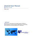
Hiding and Showing Layers
By default, layers opened in GeoViewer are displayed in the Map pane, but you can choose not to display any layer by hiding it on the Project pane. For example, you may wish to view just one tile of a
mosaic. By hiding the layers representing the other tiles, you can pan and zoom more efficiently in the
layer you’re interested in. Hiding and showing layers is different from selecting and deselecting them
(for more information see "Selecting and Deselecting Layers" on page 24).
To hide a layer, clear the checkbox next to its name in the Project pane.
To show a layer again, select the checkbox next to its name in the Project pane.
TIP: To hide or show multiple layers at once, select them in the Project pane, then right-click anywhere in the selection and choose Hide/show layers from the context menu.
In the illustration below a project has been opened that contains a number of mosaicked image tiles.
Each tile is treated as a layer; however, several layers have been hidden (their checkboxes have
been cleared), which means that these layers are not currently displayed in the Map pane.
- 17 -
LizardTech GeoViewer 5 User Manual
When you hide a layer it disappears from the Map pane. Each of the remaining layers is displayed correctly as to its position in relation to all the other layers, whether the other layers are visible or not.
Panning
There are two methods for panning a layer in two dimensions or "2D"(for information about panning in
3D, see "Navigating in Three Dimensions" on page 21):
l
l
"Quick panning" using the Overview pane for bringing the region of the map of most interest to
you quckly into the Map pane.
Using the Pan tool for fine tuning the view
To "quick pan" a layer, click and drag in the Overview pane to move the navigation rectangle
until it encompasses the region you wish to view.
TIP: Quick panning is most useful after you have zoomed in a level or two. In the original
("home") view the navigation rectangle is not visible until you pan or zoom. Similarly, the navigation
rectangle is not visible at views zoomed out beyond home view.
- 18 -
Chapter 4: Viewing Maps and Layers
To pan a layer using the Pan tool:
1. Click the Pan icon on the toolbar (alternatively, choose Pan from the Navigation menu or
from the Map context menu).
2. Click and drag on the layer in the Map pane. This brings areas outside the pane into view. The
navigation rectangle in the Overview pane (see "The Overview Pane" on page 7) shows you
what portion of the layer the Map pane is displaying.
Zooming In and Out
There are many methods for zooming into and out of a layer or map:
l
l
l
l
l
l
l
Zoom in by defining an area with the Zoom In tool
Zoom in or out by increments using the Zoom In or Zoom Out tool
Zoom in or out by increments using the slider bar
Zoom in or out using the scroll wheel
Zoom to specific layer(s) using the Project context menu
Zoom in or out using the Smooth Zoom tool
Zoom out using the Home button
For information specific to zooming in or out in 3D, see "Navigating in Three Dimensions" on page 21.
Using the Zoom In and Zoom Out Tools
To define a zoom area with the Zoom In tool:
1. Click the Zoom In icon on the toolbar (alternatively, choose Zoom In from the Map context
menu). The cursor changes to indicate that you are using the Zoom In tool.
2. Click and drag with the cursor to draw a rectangle on the map. The view refreshes and the area
you defined is displayed to best fit in the Map pane.
To zoom in or out by increments using the Zoom In or Zoom Out tool:
1. Click the Zoom In or Zoom Out icon on the toolbar (alternatively, choose Zoom In or Zoom
Out from the Map context menu).
2. Click on the map where you wish the zoomed-in or zoomed-out view to be centered. Click
again until you arrive at the desired zoom level. The navigation rectangle in the Overview pane
shows you what portion of the image the Map pane is displaying.
Using the Slider Bar
To zoom in or out by increments using the slider bar, do one of the following:
l
l
Click and drag the knob on the slider bar above the Map pane
Click on the slider bar anywhere to the left or right of the knob
Using the Scroll Wheel
If your mouse has a scroll wheel, you can zoom in and out simply by rolling the wheel back and forth.
The advantage of this method is that you do not have to be in Zoom In or Zoom Out mode to do this.
- 19 -
LizardTech GeoViewer 5 User Manual
You can zoom back and forth when another tool is selected, for example while you are panning or
measuring.
Using 'Zoom to Layer'
To zoom to specific layer(s) using the context menu:
1. Right-click a single layer name in the Project pane, or select several layer names in the Project
pane and right-click anywhere in that selection. The Project context menu appears.
2. Choose Zoom to layer(s). The layer or layers you selected are displayed at best fit in the Map
pane.
Using the Smooth Zoom Tool
Using the Smooth Zoom tool gives you fine control over the view.
To zoom in or out using the Smooth Zoom tool:
1. Click the Smooth Zoom icon on the toolbar.
2. Click in the Map pane and drag downward to zoom in or upward to zoom out.
NOTE: In quick zooming the centerpoint of the view remains constant. If you are using the Smooth
Zoom tool and wish to pan left or right, you must click out of Smooth Zoom mode and into Pan mode
using the Pan tool.
3D Viewing
Using the 3D viewing mode enables you to orbit, pan and zoom your LiDAR layers in three dimensions. The 3D tab becomes available when you add a LiDAR file to the Project pane. Supported
LiDAR input formats are LAS and MrSID Generation 4 (MG4).
The illustration below shows GeoViewer with the 3D tab selected. Notice that the Orbit Focal Point
and Refresh Points buttons are available on the toolbar. These options are also added to the Map context menu.
When you first view a layer on the 3D tab your viewpoint is positioned at the "top" of your z axis, and
the Map pane shows only the region that was visible on the 2D tab. Thus, if you zoom in on the 2D tab
before clicking the 3D tab, only points for the region that was showing on the 2D tab are displayed on
the 3D tab.
The UI Preference dialog enables you to customize several aspects of 3D viewing, such as whether
or not the focal point axes and the bounding box are shown, and to select a different color gradient
(see "3D Viewing Preferences" on page 42).
NOTE: Layers that have no z data will not be displayed in 3D mode.
- 20 -
Chapter 4: Viewing Maps and Layers
Navigating in Three Dimensions
Three dimensional viewing is complex and the tools you use to pan and zoom a flat 2D image may
seem unintuitive when you're using them for 3D viewing. So let's take a closer look and establish a
metaphor for what's really happening in 3D mode.
Imagine that when you view your data, you are looking at the center of a sphere. Let's call it the orbital
sphere. The outer surface of the orbital sphere represents the infinite possible positions your viewpoint can occupy. Your focal point is always the center of an orbital sphere no matter how you navigate. When you first view your data on the 3D tab, that data is centered where the focal point is, but it
is important to recognize that the data and the focal point are not bound together.
When you orbit the data, your viewpoint is essentially revolving around the focal point, and if you have
not yet panned the data, your viewpoint is also revolving around the center of the body of data. Imagine your viewpoint swirling around on the surface of the orbital sphere like a camera on a spherical
scaffold. Relative to the viewpoint, your data appears to turn and roll around according to your orbiting
movements.
Panning the data is different in that the viewpoint does not move along the surface of the sphere, but
up and down or sideways on the plane tangential to the sphere. This makes the entire body of data
appear to move sideways or up or down, regardless of what angle you are viewing it from. What is
actually happening is that your focal point is shifting as you pan, relative to the data, so that your viewpoint now rests on the surface of a new orbital sphere.
- 21 -
LizardTech GeoViewer 5 User Manual
With all this in mind, we recommend that you simply take the navigation tools for a test drive. You will
notice several things right away.
l
Zooming in reduces the diameter of your orbital sphere. You can zoom in to the
"space" occupied by the data points so far that you can then use the orbit tool to revolve in a
very tight circle, so that the data appears to revolve behind you. In fact you are still orbiting the
focal point, but at a much tighter radius.
l
You cannot zoom in past your focal point. If your focal point is in the middle of the body of data,
it may be "in the air" above a building or other item you wish to view, and you cannot zoom in
any closer to the object behind it. In this case, you should zoom back out a little, orbit so that
you can see the relationship of your target to your focal point (make sure axes are showing –
(see "3D Viewing Preferences" on page 42) and then use the Pan tool to "move" the data so
that your focal point is behind your target.
l
If you pan far enough, it is possible to "move" your data so that it no longer lies in your orbital
sphere at all.
In a very short time, you will develop patterns of panning, zooming and orbiting that best suit your
workflow. To start out, you may want to pan a little, zoom a little, then orbit a little to explore the data,
than repeat the process, panning again as necessary to place your focal point properly in relation to
the data you wish to view more closely.
Focal Point
Your focal point is identified by three short axis markings that form what looks like a corner. They help
you orient your viewpoint among the data. You may choose not to display the axes (see "3D Viewing
Preferences" on page 42).
NOTE: The x and y coordinates of your focal point are displayed on the status bar.
Color Gradient
GeoViewer assigns a gradient color scheme to the point cloud, based on the minimums and maximums of the z values of the LiDAR layers that make up the map. These min and max z values of
each LiDAR file are taken from the file itself, and in most cases this works fine. However, there are
two cases in which this will lead to a seemingly incorrect rendering, such as the image appearing
entirely as shades of blue.
1. If the points are not evenly distributed across the range from the map's minimum to maximum
z values, the gradient coloring will appear incorrect. For example, a one million point LiDAR file
may contain 999,999 points with a z range of 100 to 200 and one point with a z value of 10000
(due possibly to sensor error). In this case, all but one of the points will be classified at the
lower end of the gradient.
2. Some LAS files are encoded with incorrect values for the bounding box of the point cloud.
Usually as a result of earlier preprocessing workflows, a typical case would be to have the
claimed z range much larger than the actual data's z range. (MrSID Generation 4 files do not
have this problem, as the bounds encoded within the file are always "tight" to the actual data's
bounding box.)
This behavior can be manually overridden (see "3D Viewing Preferences" on page 42).
- 22 -
Chapter 4: Viewing Maps and Layers
NOTE: Minimum and maximum z values that you set manually are stored in your project file.
Navigating Using Keyboard Shortcuts
The following keyboard shortcuts make navigation in 3D mode a snap:
l
l
l
While holding down the Ctrl key, click and drag up or down to zoom smoothly out or in.
While holding down the Shift key, click and drag in any direction to rotate the view.
While holding down both the Ctrl and Shift keys, click and drag to define the region you wish
to zoom to.
Refreshing Points
The Map pane shows 500,000 points of data by default. You can change this number on the 3D settings tab of the UI Preferences dialog. When you first open your data in the Map pane, those points
are distributed over the entire volume of the data. When you zoom in among the data points, shapes
and contours may be harder to see and the data may appear "thinner". You can increase the density
of points in your area of interest by clicking the Refresh Points button
.
When you refresh the points, GeoViewer again displays 500,000 points, but all of the points displayed
after the refresh command are located within your current view, which makes for greater density in
the region you are inspecting.
TIP: Refreshing points is more effective if you are viewing perpendicular to the earth or other foundational surface in your data when you refresh. If your view tilts upward toward a "horizon", then a
broader region will be included and the points will be distributed evenly throughout it. A good rule of
thumb is to zoom in closely over your target while viewing perpendicular to the ground, then refresh
your points, then orbit to explore the data.
Restoring Original View
Clicking the Home button on the toolbar restores a view of the entire map at its "best fit" in the Map
pane. In 3D mode, this corresponds to a "top down" view of the data. Clicking the Home button also
refreshes your points.
Customizing GeoViewer's Background Color
GeoViewer uses black as the viewer's default background color, but you can change this to any
desired color.
To customize the background color:
1. Choose UI preferences from the Options menu.
2. Select the Background color tab.
3. Select the Use custom background color radio button, then click Choose color. The
Select a Color dialog appears.
- 23 -
LizardTech GeoViewer 5 User Manual
4. Specify a color using the slider, the number value fields, or the hexadecimal notation field, then
click OK until all dialogs are closed.
Selecting and Deselecting Layers
Selecting and deselecting layers is different from hiding and showing them. Showing (or hiding) a
layer simply means using its checkbox in the Project pane to make it appear in (or disappear from) the
Map pane (for more information see "Hiding and Showing Layers" on page 17). Selecting layers readies them for a particular operation, such as removing them from the list or viewing their metadata.
You can select any layer in the Project pane whether it is hidden or shown.
To select a layer, click the layer's name.
TIP: Use the Shift + Click method to select multiple consecutive layers in the list. Use the Ctrl +
Click to select multiple not-consecutive layers in the list or to deselect a layer from a group you have
selected.
Once you have the desired layers selected, right click on any member of the selection to access the
Project context menu for available operations (alternatively, choose from the commands on the menu
bar).
Selecting Bands
GeoViewer enables you to specify any three bands of a multibanded or multispectral layer to view as
the red, green and blue bands, or any single band to view as the grey band. By default, if a layer has
three or more bands the first three will be mapped to red, green and blue and if there are less than
three the first band will be displayed as the grey band.
To select bands from a multispectral layer:
1. Right click a layer or selection of layers in the Project pane and choose Select bands from the
context menu. The Select Bands dialog appears as shown below.
- 24 -
Chapter 4: Viewing Maps and Layers
2. Select bands from the drop-down menus for each of the three bands (or the grey band), then
click OK.
NOTE: Band selection is disabled in the following cases:
l
l
l
l
The selection is a CMYK or CMYK+alpha image or contains a CMYK or CMYK+alpha image.
The selection includes both RGB images and RGB+alpha images.
The selection includes images with different numbers of bands (for example a grayscale
image and an RBG image).
The selection in the Project pane includes a "group" label.
Viewing Layer Metadata
GeoViewer enables you to view the metadata of the layers loaded into the Project pane as well as
basic image and file information.
To view metadata for a layer or layers:
1. In the Project pane, select one or more layer names. Layers do not have to be showing in the
Map pane for you to view their metadata.
2. Right-click anywhere in the Project pane and choose View layer metadata from the context
menu.The Layer Metadata pane appears.
TIP: When viewing metadata for a single layer, you may combine the steps above by right-clicking
to select the name.
- 25 -
LizardTech GeoViewer 5 User Manual
Organization of the Layer Metadata Pane
The Layer Metadata pane is divided into two sides. The left side is a navigation outline listing the
names of any layers you selected and under each name several types of information. If any item of
the outline is collapsed you may expand it by clicking the arrow next to it. Each layer is listed separately in the outline.
The right side displays the details for the item selected in the outline.
Under each layer name, information is listed that might include the following, depending on the file format and the source of the layer:
l
l
l
l
l
l
l
l
l
l
- 26 -
Image properties – width, height, number of bands, color space, sample type, bits per sample,
format and compression ratios.
Vector properties – number of shape layers, layer name, layer feature count and format.
LiDAR properties – format; number of points; min, max, scale and offset for x, y and z; and
supported fields.
Geographic properties – left, top, right and bottom coordinates; x and y resolution; CRS name;
and well-known text string (WKT).
File properties – full layer path, size, creation time, modification time, attributes, and owner.
Express Server properties – root URL; server, layer name and catalog; spatially indexed (true
or false).
WMS properties – root URL; GetCapabilities URL; server; layer name and title; CRS (may
appear as SRS); format; and bounding box.
JPIP properties – root URL; server, layer name and port.
Metadata
o Basic Metadata – original file size, input format, original file name, encoding SDK version, encoding modifications, image width and height, image colorspace, image data
type, NODATA pixel value, transparent pixel value, geographic (x,y)-origin, x and y resolution, and well-known text string (WKT).
o IMAGE tags – all IMAGE:: tags
o GeoTIFF tags – all GEOTIFF_CHAR:: and GEOTIFF_NUM:: tags
o All tags – combined list of GeoTIFF and IMAGE tags
LAS properties – ProjectID and generating software.
Chapter 5: Working with Coordinate Reference Systems
Chapter 5:
Working with Coordinate Reference Sys-
tems
In order to display georeferenced images in proper relation to one another, GeoViewer must put all layers into the same projection or coordinate reference system (CRS). Changing an image's CRS is
called reprojecting.
Setting the CRS for a Map
When you add the first layer to your map, GeoViewer asks whether you want the layer to be added in
its native CRS or be reprojected to WGS84. This first decision determines the CRS for the map. You
must create a new map if you want to display your layers in a different CRS.
Reprojecting to WGS84 has the following advantages:
l
l
l
l
WGS84 is the industry default
WGS84 corresponds to latitude/longitude (lat/lon)
WGS84 is easily converted to and from other projection systems
GPS uses WGS84
If the first layer has no CRS, it is added to the map in "pixel space", that is, having a nongeographic
CRS corresponding to image coordinates.
TIP: You can set your preferences so that GeoViewer always reprojects an image to WGS84 or
always uses the native CRS (see "Setting Georeferencing Preferences" on page 41). This way, GeoViewer will not need to query you each time you add the first layer to a project.
Reconciling Projections Among Layers
The first layer to be loaded determines the coordinate reference system (CRS) for the map. Layers
added after the first layer are put into the CRS you specified for the first layer, except in the following
cases: l
l
l
The subsequently added layer is in pixel space. In this case, the layer's coordinates are
treated as being in the same CRS as that of the map, when they may not be.
The subsequently added layer has no georeferencing. In this case, the subsequently
added layer is positioned in the map using any geocoordinates available, such as information
in a world file.
The subsequently added layer is a LiDAR file. In this case reprojection is not supported.
WARNING: Either of the first two cases above may result in undesirable positioning of that layer,
so you should not import a nongeoreferenced layer unless you are fairly confident that you know
what CRS it is projected in.
- 27 -
LizardTech GeoViewer 5 User Manual
By default, you are notified whenever there is a potential mismatch in projections. If you wish, you
can use your preference settings to have GeoViewer always handle these cases in specified ways
(see "Setting Georeferencing Preferences" on page 41).
NOTE: Some reprojections, such as WGS84 to UTM, may yield errors or unusable results.
- 28 -
Chapter 6:
Working with Projects
When you run GeoViewer, the application opens an untitled project for the layers you wish to view.
Every layer you add automatically becomes part of the project. This temporary project is either saved
as a project file or discarded when you close GeoViewer at the end of your viewing session.
Saved GeoViewer projects carry a “.gvp” extension.
Only one GeoViewer project can be open at a time.
Creating a New Project
New GeoViewer projects are automatically created in two ways:
l
l
When you run GeoViewer, the application opens to an untitled project.
When you choose Close project from the File menu, your current project, whether you save it
or not, is replaced by a new untitled project.
Opening an Existing Project
To open an existing project:
1. Select Load project from the File menu. The Open dialog box appears.
2. Browse directories for the desired ".gvp" file and click Open.
Project Files Made with Earlier Versions of GeoViewer
If a project file made with GeoViewer 4.0.1 or earlier is opened in GeoViewer 5, it will be translated
into memory so that you can use it but it will not automatically be saved upon closing.
To replace the older version of the project file, choose "Save project" from the "File" menu.
To save a new version of the project file and retain the original, choose "Save project as"
from the "File" menu.
In either case, a new "version 5".gvp file is created, which can be opened, used and saved normally
thereafter.
Organizing Layers
The Project pane gives you several ways to organize layers to your advantage. You can create new
groups of layers, and you can drag layers around within a group or from one group to another.
Moving Layers
Layers are displayed in the Map pane in a kind of "stack" whose order (called the Z order) precisely follows that of the Project pane. Layers that are higher up in the list in the Project pane are displayed on
top of other layers that share the same area. The top layer obscures those beneath it except where
- 29 -
LizardTech GeoViewer 5 User Manual
there is transparency or "nodata" (see "Viewing and Setting Layer Transparency Values" on page 31).
You can move layers within a group or move a layer from one group to another.
To change the position of a layer in the Z order, click on its name and drag it up or down in
the list.
TIP: To get the best map display, put your vector layers “above” your image layers in the Project
pane. If you reverse them in the Z order your shapefile borders may be uncharitably rendered.
Grouping Layers
An initial group is created when you add your first layer.
Creating new layer groups enables you to organize your imagery. For example, you may group layers
according to years or regions. By placing layers of the same year together in a group, you can hide or
show that group with a single click to examine changes in annual increments (see "Hiding and Showing Layers" on page 17). Likewise, organizing by region groups enables you to quickly compare differences across locations.
Your workflow may suggest other groupings, such as by layer source, job, analyst, etc.
To create a new group:
1. Choose Add group from the File menu or from the Project context menu. The Add Group
dialog appears.
2. Enter a name for your group and click OK.
NOTE: The presence of a group does not in itself affect the Z order. However, moving one group
above or below another does affect position in the Z order of all the layers in the repositioned groups.
Renaming a Group or Layer
You may change the name of any group or layer.
To rename a group or layer:
1. Right-click the group or layer name in the Project pane and choose Rename from the context
menu. The Rename Group or Rename Layer dialog appears.
2. Enter a new name for your group or layer and click OK.
Removing a Layer from a Project
You can either hide a layer so that it is not displayed in the Map pane or remove it from the project. If
you are likely to want to view the layer again in the context of the current project, consider hiding it
instead of removing it (for more information see "Hiding and Showing Layers" on page 17).
- 30 -
Chapter 6: Working with Projects
To remove a layer or layers from a project:
1. If more than one layer is to be removed, select the names of all layers to be removed on the
Project pane.
2. Right click the layer name or selection of names and choose Remove selected from the context menu. Alternatively, choose Remove selected from the Layer menu.
To remove all the layers in a project, choose "Remove all" from the Project context menu or
from the "Layer" menu.
NOTE: Removing all layers does not create a new project nor does it close the current one. The
CRS established for the map is still in effect even though you have removed all layers.
Viewing and Setting Layer Transparency Values
GeoViewer enables you to specify which color of a raster layer will be transparent. Setting the layer
transparency or "nodata" values enables you to create mosaics of overlapping images.
You may set all bands in the layer to black, white, the image's native transparency values, or any arbitrary set of values.
To view and set a layer's transparency values:
1. In the Project pane, right-click the appropriate layer's name and choose Set layer transparency. The Set Transparency dialog appears as shown below. By default, the layer's native
values are displayed and used.
- 31 -
LizardTech GeoViewer 5 User Manual
If native values have previously been overridden, the Edit Override radio button is selected and
override fields appear to the right displaying the override values previously set, as shown
below.
2. Click the radio button closest to your desired settings.
l Set all bands to minimum value – Specifies that the layer's transparency color be
black (all bands have values of 0). If they are not already visible, Override fields appear.
l Set all bands to maximum value – Specifies that the layer's transparency color be
white (all bands have the maximum transparency value – for an 8-bit RGB image this
would be 255). If they are not already visible, Override fields appear.
l Use native layer transparency – Specifies that the layer's native values be used.
l Edit Override – Enables you to specify values for each band.
3. If you select Edit Override, the Override appear as shown below. If native values have previously been overridden, the override fields display the values previously set. Enter desired
values.
- 32 -
Chapter 6: Working with Projects
4. Click OK.
NOTE: If you selected Set all minimum or Set all maximum, the Edit Override button will be
selected the next time you access this dialog, but the fields will remain populated with minimum or
maximum values until you change them.
Saving a Project
You may save a project at any time. You will be prompted to save any changes you wish to keep
when you close GeoViewer.
Saved GeoViewer projects carry a “.gvp” extension.
To save a project:
1. Choose Save project or Save project as from the File menu. If you choose Save project
as, the Save As dialog box appears.
2. Specify a name and a folder and click Save. A new GeoViewer project (“.gvp”) file is created.
For information on project files made with GeoViewer 4.0.1 or earlier, see "Project Files Made with
Earlier Versions of GeoViewer" on page 29.
- 33 -
Chapter 7:
Measuring Distance
In 2D mode GeoViewer enables you to measure the distance between two points or the total distance
of several line segments drawn on a map with the Measuring tool. When you use the Measuring tool,
the Measurement pane appears in the Map pane.
Besides showing you the distances among the points you measure, the Measurement pane indicates
the display unit (the measurement unit your distances are to be reported in) and the source unit (the
measurement unit the image was originally georeferenced in), and allows you to set the display units
as you desire.
To use the Measuring Tool or access the Measurement pane do one of the following:
l
l
l
Click the Measure icon on the toolbar.
Choose Measure from the Tools menu.
Right-click in the Map pane and choose Measure from the context menu.
Using the Measure Tool
Taking Measurements
To measure the distance between two points:
1. Click the Measure icon on the toolbar (or choose Measure from the Tools menu) if the Measure tool is not already active. The Measurement pane appears.
2. Click in the Map pane at the point where you wish to begin measuring.
3. Click the map again at a second point. The distance between these points is listed in the Segment Length(s) field preceded by "1:" (Note: For a single measurement, this distance is also
the value reported as the Total Length below the Segment Length(s) field).
To measure the total distance of several line segments:
1. Perform steps 1 – 3 above.
2. Click the image again at a third point, and a fourth, etc. Each time a point is clicked on, the distance between that point and the previous point is added to the distance displayed in the "Total
- 35 -
LizardTech GeoViewer 5 User Manual
Length" field, as shown below.
NOTE: By default, measurements are displayed in the same unit as the source units of the image.
To change the display unit, see "Setting Measurement Units" on page 37.
Clearing Measurements
To clear the measured points so you can perform a new measuring operation, do one of the
following:
l
l
Click Clear measurements in the Measurement pane.
Choose Clear measurements from the Tools menu.
Copying Measurement Data for Use Elsewhere
To use the collected measurement data elsewhere, click Copy data to clipboard, then paste
the data into another application.
Closing and Reopening the Measurement Pane
You can close the Measurement pane by clicking the X in the upper right corner.
If you wish to see it again, click the Measure icon again or right-click the image and choose Measure
from the context menu.
- 36 -
Chapter 7: Measuring Distance
Getting Out of Measurement Mode
To get out of Measurement mode, click any other tool icon.
Setting Measurement Units
In order to report measured distance, GeoViewer needs to know both the measurement unit in which
your image was first georeferenced ( the source unit) and what unit you want the results of your measurements reported in (the display unit).
The Display Unit
If you have never changed the display unit, the default display unit for a given image is the same as
its source unit. Once you have specified a display unit, that unit will be the default display unit until
you change it again.
For images with known source units, you can choose any of the following display units:
l
l
l
l
l
meters
kilometers
feet
miles
pixels
To specify a display unit:
1. Click the Measure icon on the toolbar (or right-click in the Map pane and choose Measure
from the context menu) if the Measure tool is not already active. The Measurement pane
appears.
2. In the Measuring pane, select a measurement unit from the Display Units drop-down menu.
The Source Unit
GeoViewer reads the source units of a georeferenced image (meters, kilometers, feet, miles or
"other") when you add it as a layer. That unit is reported as the native unit in the Source Unit dropdown in Measurement pane, and this drop-down becomes unavailable.
You may have images for which the source measurement unit is not known. For example, the geocoordinates for your image may be stored in a world file, or it may have no geocoordinates at all.
For such cases, GeoViewer enables you to supply the source unit yourself. If you know the ground
resolution (how many feet, meters or other units each pixel of the image represents), you can enter
the appropriate source unit and select any desired display unit.
If you do not know the image's ground resolution, then you should set the display unit to pixels. When
the display unit is set to pixels, the source unit is ignored.
To specify a source unit:
1. Click the Measure icon on the toolbar (or right-click in the Map pane and choose Measure
from the context menu) if the Measure tool is not already active. The Measurement pane
- 37 -
LizardTech GeoViewer 5 User Manual
appears.
2. In the Measuring pane, select a measurement unit from the Source Units drop-down menu.
- 38 -
Chapter 8:
Exporting Maps and Layers
In 2D mode, GeoViewer enables you to save a particular view or an entire map as a GeoTIFF, PNG or
JPEG file.
NOTE: LiDAR data can only be exported as two-dimensional layers.
Exporting the Current View
Exporting the current view creates a file of exactly what you see in the Map pane at that moment
(minus the Measurement pane, if it is open).
Exporting a Map
When you export a map, GeoViewer creates a file showing the region covered by all the layers in the
map (called the minimum bounding box), regardless of which layers are hidden or shown.
This means that if your map includes six mosaic tiles of equal size and you have hidden five of them
(by deselecting them – see "Hiding and Showing Layers" on page 17), the single layer you have left
selected will be the only layer visible in the exported image, but it will take up only one sixth of the
exported image's area and it will be positioned in proper relation to the five invisible ones.
To export a view or an entire map:
1. Select Export from the tools menu, then choose Export current view or Export map. The
Export Map or Export View dialog appears.
2. Select a file format from the Format drop-down menu. You can save your view or map as a
GeoTIFF, PNG or JPEG.
3. Select a resolution from the Resolution drop-down menu. The default resolution is Medium
(2048 x 2048 pixels). Note that the dimensions at Full resolution depend on those of the source
image.
4. Verify the compression quality for JPEG or PNG using the slider in the JPEG Options or
PNG Options panel. For JPEG, higher quality will result in greater visual detail. PNG is a lossless format, so a higher compression quality here simply takes more time to export and
creates a slightly smaller file.
5. [Optional] If you want a world file to be created, select the Write world file checkbox.
6. Enter a path and file name (alternatively, click Browse to select an output file path, choose a
folder and file name, and click Save).
7. Click OK.
Your file is created in the folder you specified.
- 39 -
Chapter 9:
Preferences
GeoViewer enables you to set your preferences for how layers' georeferencing is handled, for colors
and other aspects of the user interface, and for reminders to check for updates.
Setting Georeferencing Preferences
The georeferncing preferences enable you to specify whether or not world files should be read, how
coordinate reference systems (CRSs) should be reconciled among layers, and what warnings you
would like to receive.
Read World Files
If world files are present and the "Read world files" checkbox is selected, information in metadata will
be ignored in favor of the world file.
By default this checkbox is clear and world files are not read.
Coordinate Reference System Reconciliation
You can specify one of the following as GeoViewer's default behavior when a layer is added to the
map:
l
l
l
Reproject added layers to WGS84
Use layer's native CRS
Ask me what to do
NOTE: When a world file is present and the "Read world files" checkbox and the "Use layer's native
CRS" radio button are both selected, world files will take precedence over native georeferencing.
Warnings
There are cases where reprojection is not possible or the layer has no native CRS (see "Reconciling
Projections Among Layers" on page 27). By default GeoViewer warns you in these cases and also
when it is about to reproject a layer to WGS84.
TIP: When you are warned that an layer is about to be reprojected, you have the opportunity to
select the "Always reproject without asking" checkbox. This clears the "Warn me before reprojecting
layer" checkbox in your preferences.
Setting User Interface Preferences
You may change the look and feel of the GeoViewer interface using your UI preferences settings.
To set or change preferences:
1. Choose UI Preferences from the Options menu. The UI Preferences dialog box appears.
2. Select a tab on the left and make desired changes (see below).
- 41 -
LizardTech GeoViewer 5 User Manual
3. Click OK.
Status Bar Preferences
The CRS of the map is shown in the status bar in the lower left corner. The status bar also tells you
whether GeoViewer is idle or working, and shows your cursor position in several common georeferencing modes. You can choose to show or hide the status bar and which modes your cursor position is reported in. Latitude/Longitude and Native are selected by default.
Latitude/Longitude can be expressed decimally or by DMS (degrees, minutes, seconds). Decimal is
the default.
Viewer Background Preferences
When you view your map at a level such that it does not completely fill the Map pane, the viewer background is visible around the region occupied by your map. By default GeoViewer uses black. You may
choose a custom color for the background if you wish.
Line Weight, Line Color and Layer Names
You may select the width and color of most lines in the user interface, such as vectors, measurements and layer boundaries in the Map pane, and the navigation rectangle in the Overview pane.
You may also turn layer boundaries on or off and enable the layer name tool tip, which displays a layer's name when you hover over it in the Map pane.
NOTE: Vector settings can also be specified for a particular layer on the Layer menu or the Project
context menu (see "Context Menus" on page 12).
Tips and Tricks
You may disable the Tips and Tricks dialog so that it is not displayed when you run GeoViewer. You
can always access Tips and Tricks from the Help menu or by clicking the GeoViewer icon
toolbar.
on the
3D Viewing Preferences
Several aspects of viewing on the 3D tab can be changed. You can enter a value by which to exaggerate the z axis, which will bring features into greater relief. The number of points displayed at once
can also be raised or lowered from the default of 500,000.
For the color gradient that helps you visualize different elevations in the data, you can select from a
drop-down menu of 23 choices. You can also manually override GeoViewer's automatic z range
behavior and supply your own minimum and maximum z values for your map.
NOTE: Minimum and maximum z values that you set manually are stored in your project file.
Finally, you can show or hide the focal point axis markings or the bounding box of the data (by default,
both are shown).
- 42 -
Chapter 9: Preferences
Setting GeoViewer Update Preferences
The GeoViewer update preferences enable you to specify that GeoViewer should remind you to
check for a newer version, and how often it should remind you (for information about checking for
updates manually, see "Chapter 2: Installing or Updating GeoViewer" on page 3).
By default GeoViewer reminds you every 7 days to check for a new version.
To change the number of days between reminders:
1. Choose GeoViewer update preferences from the Options menu. The GeoViewer Update
Preferences dialog appears.
2. Enter a number of days and click OK.
GeoViewer will remind you check for updates at the frequency you specified to. If a new version
becomes available, the Check Updates dialog appears and you may download the new version (see
"Chapter 2: Installing or Updating GeoViewer" on page 3).
To disable the reminders:
1. Choose GeoViewer update preferences from the Options menu. The GeoViewer Update
Preferences dialog appears.
2. Clear the Remind me to check for updates checkbox. The "Remind me every x days" field
becomes unavailable ("grayed out").
3. Click OK.
- 43 -
Appendix A: Technical Information
Supported File Formats
Input Formats
The following table lists the file formats GeoViewer opens along with their file extensions:
File Format Name
Extension(s)
ECW
.ecw
ERDAS IMAGINE
.img
ERDAS LAN
.lan
ESRI Shapefiles
.shp
GeoTIFF and TIFF
.tif .tiff
JPEG 2000
.jp2
LAS
.las
LizardTech MrSID (including
MG4)
.sid
NITF
.ntf
Original JPEG
.jpg
PNG
.png
Raw (uncompressed) BBB
.bil .bip .bsq
Sun Raster
.ras
USGS DOQ
.nes .ses .nws .sws .doq
Windows Bitmap
.bmp
NOTE: LAS and MG4 files must be stored on a local computer or network.
See also "Adding a Layer to View" on page 15.
All of the supported input formats can take world files except LAS and MG4.
TIP: The rule for arriving at the proper world file extension for a given file format is that the first and
third letters of the format's extension are taken and a "w" is appended after them. Thus, a world file
for a MrSID (".sid") file would have the extension ".sdw".
- 45 -
LizardTech GeoViewer 5 User Manual
Output Formats
The following table lists the file formats in which GeoViewer exports images along with their file extensions:
File Format Name Extension(s) GeoTIFF
.tif
PNG
.png
JPEG with world files
.jpg See also "Chapter 8: Exporting Maps and Layers" on page 39.
Viewing System Information
The System Information pane includes details pertaining to your installation of GeoViewer, including
the full build version numbers and URLs for the application's installation directories. This information
can be used to troubleshoot problems or submit bug reports.
To view system information, choose System Information from the Help menu.
- 46 -
Appendix B: Product and Company Information
Displaying Tips and Tricks
When you open GeoViewer, a dialog displays information that might help you work more efficiently,
as shown below. The information may be a procedural tip, a shortcut or other trick, or even a promotional note.
From this dialog you can use the buttons to view the previous tip, the next one, or all of them at once,
and you can instruct GeoViewer not to show you tips and tricks on startup anymore.
To prevent the Tips and Tricks dialog from appearing on startup, clear the "Show tips at
startup" checkbox.
To access the Tips and Tricks dialog later, click the GeoViewer logo
choose "Tips and Tricks" from the "Help" menu.
on the toolbar or
Displaying the GeoViewer About Box
Information about which version of GeoViewer you are running is available in the About box, shown
below. The About box also contains copyright information.
- 47 -
LizardTech GeoViewer 5 User Manual
To view the About box, choose About GeoViewer from the Help menu.
About LizardTech
Since 1992, LizardTech has delivered state-of-the-art software products for managing and distributing
massive, high-resolution geospatial data such as aerial and satellite imagery and LiDAR data. LizardTech pioneered the MrSID® technology, a powerful wavelet-based image encoder, viewer, and file format. LizardTech has offices in Seattle, Denver, London and Tokyo and is a division of Celartem
Technology Inc. (JASDAQ: 4330). For more information about LizardTech, visit www.lizardtech.com.
Other LizardTech Products
Thank you for using LizardTech™ GeoViewer. We at LizardTech are glad to have you as a customer.
While you’re “in the shop,” explore LizardTech’s other products for managing high-quality images and
documents.
ExpressView Browser Plug-in
Fast and Easy Viewing of Large Images
If you like the features in GeoViewer, consider ExpressView Browser Plug-in. ExpressView enables
you to view, navigate and print MrSID and JPEG 2000 imagery in Internet Explorer or Firefox. Like
GeoViewer, ExpressView enables you to save a portion of an image in a number of other image formats. ExpressView Browser Plug-in is quickly downloaded, easily installed, and free for individual
use. It's the most convenient way to view MrSID and JPEG 2000 imagery over networks!
For more information about ExpressView Browser Plug-in visit
http://www.lizardtech.com/download/.
ExpressView Browser Plug-in
Fast and Easy Viewing of Large Images
ExpressView™ Browser Plug-in enables you to view, navigate and print MrSID and JPEG 2000
imagery in Internet Explorer or Firefox. Like GeoViewer, ExpressView enables you to save a portion
of an image in a number of other image formats. ExpressView Browser Plug-in is quickly downloaded, easily installed, and free for individual use. It's the most convenient way to view MrSID and
JPEG 2000 imagery over networks!
For more information about ExpressView Browser Plug-in visit http://www.lizardtech.com/downloads/viewers.php.
GeoExpress
The Industry’s Best Image Manipulation and Compression Software
With powerful tools for reprojecting, color balancing, and mosaicking, GeoExpress® software is the
industry’s choice for manipulating and compressing geospatial imagery to industry standard formats.
- 48 -
Appendix B: Product and Company Information
You can configure Express Server and Spatial Express® software directly from GeoExpress, which
makes it the ideal command center for your storage and distribution workflows.
For more information about GeoExpress visit www.lizardtech.com/products/geo/.
LiDAR Compressor
LiDAR Data Meets the MrSID Format
LizardTech LiDAR Compressor™ software enables you to turn giant point cloud datasets into efficient MrSID files that retain 100 percent of the raw data at just 25 percent or less of the original file
size (lossless compression). If storage requirements are critical, you can reduce your LiDAR file
sizes by 90 percent or more by choosing a higher compression ratio and letting LiDAR Compressor
select the best way to reach a desired file size (lossy compression). Unlike raw LAS or ASCII data,
LiDAR files compressed to MrSID are easily managed resources you can extract derivatives from
again and again.
For more information about LiDAR Compressor visit www.lizardtech.com/products/lidar/.
Express Server
Image Delivery Software for Geospatial Workflows
LizardTech Express Server software is the best solution for distributing imagery in MrSID or JPEG
2000 format. With Express Server, users on any device access imagery faster, even over low-bandwidth connections. Express Server is faster, more stable and easier to use than any other solution for
delivering high-resolution raster imagery.
For more information about Express Server visit http://www.lizardtech.com/products/exp/.
MrSID Decode SDK
Integration of MrSID Support into Third-Party Applications
The MrSID Decode SDK provides a framework for extracting raster or LiDAR data from MrSID files,
including MrSID Generation 4 (MG4™). Used as the foundation for LizardTech's LiDAR Compressor™ and its Express Suite® line of geospatial products – GeoExpress, Express Server and Spatial Express software – the MrSID Decode SDK is a robust toolkit suitable for complex application
development needs.
MrSID Decode SDK is available for free download at http://developer.lizardtech.com.
GeoViewer and Patents
This software is protected by U.S. Patent Nos. 7,218,789, 7,454,084, 7,508,991 and 5,710,835;
Canadian Patent No. 2,236,943; and European Patent No. 0,864,135 and by additional U.S. and Foreign Patents Pending.
- 49 -
Index
3
E
32-bit
3D viewing
1
20
6
Earlier versions
29
Exporting maps and layers
39
F
64-bit
1
A
File formats
45
File menu
8
22
About box
47
Focal point
Accessing the Measure tool
35
G
Adding a layer
15
Georeferencing
from local directory
15
preferences
41
via Express Server
15
reconciling
27
via JPIP server
17
GeoViewer update preferenences
via WMS
16
GeoViewer user interface
7
Axis markings
22
Getting oriented
7
B
Grouping layers
30
Bands
H
selecting
24
Help menu
setting layer transparency
31
Hiding layers
C
Checking for Updates
43
8
17
I
3
Images
Clearing measurements
36
opening Express Server images
15
Context menus
12
opening from local directory
15
Coordinate reference systems
27
opening via WMS
16
Copying measurement data
36
opening via WMS server
17
Creating a new group
30
projections
27
Creating a new project
29
D
Installing GeoViewer
3
K
Displaying the GeoViewer About box
47
Displaying Tips and Tricks
47
Keyboard shortcuts
23
- 51 -
LizardTech GeoViewer 5 User Manual
L
N
Layer metadata
Layers
25
2
Navigating using keyboard shortcuts
23
Navigation in three dimensions
21
adding from local directory
15
Navigation rectangle
adding via Express Server
15
Nodata
adding via JPIP server
17
O
adding via WMS
16
Opening an existing project
29
grouping
30
Opening an image
15
organizing
29
from local directory
15
projections
27
via Express Server
15
rearranging
29
via WMS
16
removing from project
30
via WMS server
17
renaming
30
LiDAR
Options menu
8
29
48
20
Other LizardTech products
coordinate reference systems
27
Overview pane
supported formats
45
P
LiDAR data, exporting
39
Map
31
Organizing layers
3D viewing
M
7
Panning images
7
18
Preferences
2
georeferencing
41
Map pane
11
GeoViewer updates
43
Measurement pane
35
user interface
41
Measurement units
37
Project
Measurements
creating new
29
clearing
36
opening existing
29
copying measurement data
36
saving
33
taking
35
Project files
29
Menu bar
8
Project pane
12
27
MG4
45
Projections
Moving layers up and down in the Project pane
29
R
MrSID Generation 4
45
Multispectral (multibanded) layers
24
- 52 -
Reconciling projections among layers
27
Refreshing points
23
Index
Removing a layer from a project
30
Update reminders
Renaming a group or layer
30
Updating GeoViewer
Reprojecting images
27
User interface
Resolution
map of
of exported maps or views
39
Restoring GeoViewer to its previous state
4
43
3
7
preferences
41
V
Restoring original view
23
Version number
47
Right-click menus
12
Viewing and setting layer transparency values
31
Viewing layer metadata
25
Viewing system information
46
S
Saving a project
29, 33
Selecting and deselecting layers
24
W
Selecting bands
24
WGS84
27
Setting georeferencing preferences
41
World files
39
Setting GeoViewer update preferences
43
Z
Setting measurement units
37
Setting the coordinate reference system for a map
27
Setting user interface preferences
41
Showing and hiding axes
22
Showing layers
17
Source measurement units
37
Status bar
12
Supported formats
45
System information
46
System requirements
Z-order
29
Zooming in and out
19
1
T
Taking measurements
35
Tips and tricks
47
Toolbar
10
Tools menu
Transparency
8
31
U
Uninstalling GeoViewer
4
- 53 -