1
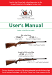
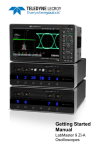
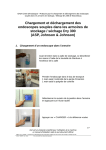
MANTHEI MESS SYSTEME
The Trigger Scan System
Computerized Trigger Analysis
We show feelings!
Vers. 1.1 gb. oV
© 1999 MMS
MANTHEI MESS SYSTEME
Thank you for your interest in the Trigger Scan system. We would like to
introduce you to the possibilities of this instrument. The presentation
offers different ways to explore the Trigger Scan system. Choose the
desired path by placing the cursor on the colored text and clicking on it
with the left mouse button. To reach the next screen just push any key or
the left mouse button. Please wait until the ! sign disappears and the "
sign in the lower right corner of the screen appears to ensure that all
animations of this page are finished. To return to the main menu at all
times, place the cursor on the " sign in the lower right corner clicking on
it with the left mouse button. The end of any path will take you
automatically to the main menu.
If you have further questions, please do not hesitate to contact us.
© MMS 1999
Axel Manthei
Bahnhofstraße 9
86916 Kaufering/ Germany
Tel. / Fax +49- (0) 8191-66704
email: [email protected]
"
!
back
Main Menu
Which information about the Trigger Scan
system would you like to get?
• The complete tour
• Information about the trigger testing
• Information about the spring testing
• View specific issues
• Where to get the system / Please continue only by
choosing one of the
contact to MMS
topics with a mouse
• exit presentation
click!
© MMS 1999
"
!
The Trigger Scan system can
•
•
•
•
•
•
graphically display the trigger pull
numerically analyze the trigger pull
measure the lock time
graphically display the force of springs
numerically analyze springs
measure forces
© MMS 1999
"
!
back
The data of the trigger pull will be
analyzed for :
•
•
•
•
•
•
© MMS 1999
maximum force
travel to actuate
initial take-up
over travel
energy to actuate
lock time
"
!
back
force
The trigger pull will be displayed
in the following manner
travel
© MMS 1999
numerical analysis
"
!
back
Trigger profile explained:
Travel to Actuate
Over-travel
Peak Force
Trigger
Actuation
Initial
Take-up
Energy
© MMS 1999
Striker
Impact
"
!
Lock Time
• The lock time* is measured with a probe
inserted into the barrel. The exit of the
firing pin from the breech face is detected.
• The time will be displayed in the
XX,X format in milliseconds.
* The lock time is defined as the time between the release of the trigger
and the exiting of the firing pin from the breech face.
© MMS 1999
"
!
back
The Trigger Scan Instrument
The sensor arm is motorized
and measures force during
forward and/or backward
motion.
© MMS 1999
"
!
back
The fixture
• The fixture accommodates
firearms of all kinds.
• It can be adjusted for small
pistols as well as for large
match rifles.
© MMS 1999
"
!
back
Adapter for spring measurement
• The measuring
instrument can be
easily adapted for
spring measurement
© MMS 1999
"
!
back
Spring measurement
• The graph shows a
compression profile of
a spring.
Force versus travel.
© MMS 1999
"
!
back
The spring data will be analyzed for:
• spring consistency
• stored energy
The system can compress a spring to a determined
distance or until a set force is reached. With these
features a simulation of the actual working
condition of the spring is possible.
© MMS 1999
"
!
back
Trigger Scan™ system components
•
•
•
•
•
•
•
•
Instrument with accessories
Windows® based software
Firearm fixture
Lock time sensors
Spring measuring adapter
Lockable transport case
Calibration tools
User manual
© MMS 1999
"
!
back
The Trigger Scan System consists of:
• Software:
• 3.5" installation
diskette
• Hardware:
• lockable carrying case
• the Trigger Scan
instrument
• power adapter
© MMS 1999
•
•
•
•
•
•
•
•
•
•
3 piece spring attachment
9 pin serial cable
25 pin serial port cable adapter
8" firing pin sensor
24" firing pin sensor
3 allen wrenches
1 calibration tweaker
spare calibration labels.
user manual.
rifle fixture with a pistol adapter and
an adjustable clamp.
"
!
back
The Software
The software
•
•
•
•
is easy to install
has a self explaining screen
is available in English or German
can be switched between metric and imperial
units. Already stored data will also be switched.
© MMS 1999
"
!
back
The Work Area
Control buttons for
all frequent tasks are
arranged in the work
area, and mouse
clickable.
The test results are
shown in columns
on the right side.
Test 2
Test 1
Clear
Ready
Go
Stop
Two measurements can be evaluated at a time
(e.g. Single Action and Double Action).
© MMS 1999
Return
Analyze
Print
"
!
back
The Test Procedure
Arms of the instrument
are placed in between the
trigger and the trigger
guard.
The fixed arm rests
against the trigger
guard, while the moving
arm compresses the
trigger.
© MMS 1999
"
!
back
The Results
The received data can be:
•
•
•
•
© MMS 1999
printed
stored in a file
retrieved as a file
visually compared with self defined
control limit lines
"
!
back
What information can the system
analyze on a trigger?
The system measures the force versus travel
• on the usual direction of the trigger pull
• on the return of the trigger to the home position
• on both directions of the trigger test
The force on the trigger, that is returning it to his home
position, can be of interest for the evaluation of so called
release triggers. It is also useful to ensure the proper function
of commonly used trigger systems. The necessary balance
between enough force to overcome dirt and a moderate trigger
pull can be established on scientific measurements.
© MMS 1999
Click for example
"
!
back
The use of the
Trigger Scan System
•
•
•
•
© MMS 1999
Forensic and Firearms Experts
Armories
Research and Development of Firearms
Gunsmiths
"
!
back
Forensic and Firearms experts
In the fields of forensic and firearms experts is a scientific
method of testing the trigger pull mandatory. Testing
the trigger pull with weights was a proven way to determine
the maximum force to actuate the trigger but it will not give
any information about the changes in force during the travel of
the trigger. To detect an inconsistent releasing trigger was also
difficult.
The Trigger Scan System shows multiple graphs of the same
trigger within a matter of seconds. Comparing the force vs.
travel graph enables the examiner to give a scientifically
founded statement about the consistency of the trigger system.
© MMS 1999
"
!
back
Forensic and Firearms experts
Another advantage of the Trigger Scan system over the method with
weights is the fact that the firearm is tested in the correct position
with horizontal barrel. The difference between a straight or up side
down held firearm can also be tested.
With a printed Trigger Scan graphic it is easier to explain a
characteristic to a person which is not familiar with firearm (e.i. in
court). Especially for the quality control in the forensic science it is
important that the Trigger Scan ™ system can be checked and if
necessary calibrated for proper accuracy. Forensic laboratories in
Germany, Austria, Netherlands and the USA are using the Trigger
Scan™ system with success.
© MMS 1999
"
!
back
Firearms manufacturing
- as a mean of promotion Firearms manufacturer can us the Trigger Scan System in
multiple areas.
The manufacturer of target or hunting firearms can supply a
printed trigger profile together with the rifle or pistol. In this
way it is not only documented in what state the trigger of this
particular firearm was, when it was delivered.
It is also demonstrated, that your Company is using the most
scientific tools to insure a proper quality control of the used
components.
© MMS 1999
"
!
back
Firearms manufacturing
- quality control of the productFor the production quality control is the main issue. With a
maximum duration of 15 seconds for the test cycle of the
complete trigger characteristic, a random or complete control
of the produced firearms can be done in a cost-efficient way.
The data can be stored and retrieved if necessary. Statistics
for the analysis of the production can be one application.
Inquiries of a complaining customer can be checked as well
as it could be an advantage in the case of product liability, if
one can show evidence that the trigger pull was not below or
above the production standards.
© MMS 1999
"
!
back
Example of control limits
Control limits like the shown lines can be created
easily. With the optical comparison against upper
and lower limit lines production test can also be
performed by scientific uneducated personal.
Upper limit at example at 25 Newton
The tested firearm is meeting
the required standards.
!
The lower limit is as example
defined at 17,5 Newton.
© MMS 1999
"
!
back
Firearms manufacturing
- research & development The development of trigger systems requires more than the
knowledge of the maximum force. The full graph of a trigger
characteristic is important. Up till now this could only be
checked by feeling with the finger, a usable but not very
scientific method. The Trigger Scan system will not only give
the force versus travel graph, the system will also analyze the
energy put in the trigger to release the firing pin. In a double
action trigger the ignition energy is put into the system via the
trigger pull. Therefor the energy to actuate the trigger - minus
the friction - gives an information about the ignition energy
and possible causes for light strikes on the primer.
© MMS 1999
"
!
back
Firearms manufacturing
- research & development Measurement of a S&W Revolver shows that 415 Nmm of
energy is needed to actuate the trigger. This energy is
consumed by compression of the springs and friction of the
internal parts. For this revolver, the energy distribution is
apparent from the graph.
Transfer bar
1 ,4 %
Component
Trigger spring
Cylinder
Main spring
Transfer bar
© MMS 1999
Energy
101,3 N mm 24,4 %
16,6 N mm 4,0 %
292,0 N mm 70,2 %
5,9 N mm
1,4 %
Trigger spring
24,4 %
Main spring
70,2 %
Cylinder transport
4%
"
!
back
The gunsmith
Rough areas in the
trigger characteristics
Variation in trigger quality between six chambers
result of uneven cylinder transport.
Customers who complain about trigger quality can visualize
the problem. After the problem is eliminated (sale of a
trigger job), another graph can be generated as a proof.
© MMS 1999
"
!
back
Firearms manufacturing
- research & development A further advantage is the possibility to test the properties of
springs delivered from a supplier. Springs are one of the most
critical parts in firearms and the spring constant has a great
influence on the reliability and the performance of the finished
product.
A delivery of springs can be checked in a matter of minutes and
a lot that exceeds the tolerances can be rejected. A supplier who
knows that his springs can be tested in a scientific way will
strive harder to stay within the given tolerance and therefor
deliver
a better product.
© MMS 1999
"
!
back
Armories
Armories who are responsible for the arms of a police department or
a military unit can obviously use the Trigger Scan system to check
triggers for the required trigger pull. To store the result in a file or
print it on paper for the individual firearm file can act as proof that
the particular firearm met the requirements when it left the armory.
With a maximum duration of 15 seconds for the test cycle of the
complete trigger characteristic, a complete control of the serviced
firearms can be done in a cost-efficient way. The time to mount the
gun can be reduced by custom preset mounts.
The characteristic of the trigger graph will also show on certain
firearms that the internal safety elements are installed.
© MMS 1999
"
!
back
Example
Missing safety elements.
You can diagnose missing parts
of the trigger mechanism based
on the trigger characteristics.
Drop safety
missing!
•
Normal curve must look
like this in the upper part.
!
© MMS 1999
✗
Stored or printed graph can be
used as evidence whether the
firearm, when it left the shop,
had all the necessary safety
elements installed.
"
!
back
Armories
The possibility to retrieve the former test files on the screen
enables the armorer to compare the current state of a trigger
against the state it was delivered the last time. “Custom tuning” by
the user of a firearm can be detected and being dealt with.
If though a “customized“ duty gun is used in a shooting and an
accidental discharge because of a to light trigger is claimed, the
armory and the armorer can proof that the firearm issued met all
requirements.
© MMS 1999
"
!
back
Armories
During the mandatory inspection of a firearm the recoil spring
and the hammer or striker spring can be tested for their
current properties. Failure to ignite or spring related feeding
problems, which are caused by weak springs can endanger
the officer or user of the firearm.
Therefore a proper and scientific method of testing of those
springs is mandatory. Weak springs can be detected and
exchanged to insure a fully serviceable firearm.
© MMS 1999
"
!
back
The gunsmith
- in the workshop A gunsmith or specialist in trigger tuning can use the Trigger Scan
System in several ways.
First of all one develops a deeper understanding for the mechanical
and physical side of trigger system. Of course the feeling in the
trigger finger of a trained gunsmith is a good way to judge a
trigger. But after working a long day on triggers the finger gets
tired and loses some of its sensitivity. The Trigger Scan System
enables one to measure the trigger pull accurate instead of only
trusting a feeling. Obviously the consistency of the trigger pull can
be checked by repeated tests. This is especially interesting on a
revolver because differences in the ratchet for each chamber will
have an influence on the corresponding trigger pull.
© MMS 1999
"
!
back
The gunsmith
- in the workshop The adjustment of a trigger system is faster and more accurate
and difficult triggers are easier to adjust.
Very fine trigger systems like set triggers or very light triggers
on match air rifles or pistols can be tested. Examples can be
seen in the demo software.
While checking a trigger during the tuning process one
develops a knowledge how the work process will have an
influence on the trigger characteristic. Senseless work habits
can be eliminated and the necessary time reduced.
© MMS 1999
"
!
back
Example
Forward and reverse test
Limit of travel
Compression
Start position of the
trigger movement
© MMS 1999
Release
Return home to the start position
"
!
back
The gunsmith
- with the customer The firearm of a customer who complains about his results with
the gun (his accuracy) can be checked for trigger problems and in
case of a faulty trigger an order for a trigger job could be the
result. The test of a firearm with the Trigger Scan system can be
charged if the gun was bought somewhere else or offered as a
bonus if a new firearm is bought. Here also an additional trigger
job could be the result.
The documentation of the trigger characteristic on a sold firearm
can act as evidence of the as sold status. Complains from
customers who did some homework and ruined the trigger on their
gun can easily be dealt with. The repair of the firearm can be
charged to the customer.
© MMS 1999
"
!
back
The gunsmith
- with the customer The advantage of after market parts for the trigger system (springs,
hammer, sear, ....) can be proofed (before - after) with a diagram.
This acts as advertising that your Company sells parts which are
proven to work.
The possibility to measure the lock time gives the advantage to test
and recommend after market parts that reduce the lock time. For
example speed locks for rifles (K98, Swedish Mauser) or
handguns (Colt, beretta, Glock ...). The print out acts as a
advertisement for the part and your shop because every print out
bears the name of your company. Those print outs will be
circulated on the shooting ranges by the proud owner of the part
and makes your shop known.
© MMS 1999
"
!
back
The gunsmith
- with the customer The Trigger Scan system will aid that your shop is known as a
modern equipped company.
Customers will be attracted by the instrument. The word (and the
print out) will go around that your company can scientifically test
triggers. People you have not seen for ages stop by to see it and get
their triggers tested. This can be done for a certain fee and as a
possible follow up a tune up of the trigger could be sold.
The Trigger Scan system is used with success by well known
custom gunsmiths, who shared their experience with us.
© MMS 1999
"
!
back
Specific Issues
•
•
•
•
•
•
•
•
the instrument
the spring adapter
lock time
the firearms fixture
the graphic
the results explained
the software
frequently asked questions
© MMS 1999
specific tasks
• Forensic
• Armories
• Manufacturing
• Gunsmithing
technical specifications
contact to MMS
current price
"
!
back
Frequently asked questions
•
•
•
•
•
•
•
•
•
•
•
•
•
How is the trigger profile created?
Can I use the Trigger Scan™ System without a Computer ?
What kind of test options exists?
Can the results be stored in a file and why should it be done?
Is there an advantage in using a larger monitor?
How are these instruments calibrated?
How can control limit lines be created?
What will the print out look like?
On what kind of firearms can the TriggerScan system be used?
Can I measure anything else besides trigger and springs with the system?
Are the data readings of the system also available in MKS units?
Product warranty, hardware and software upgrade and repair policy?
Who is using the TriggerScan™ System already?
© MMS 1999
"
!
back
Is there an advantage in using a larger
monitor with the TriggerScan software?
Yes, the resolution of the trigger profile graph
improves when you use a larger monitor. The software
recognizes the video resolution setting and increases
the area of the graph while keeping the control buttons
and texts at a comfortable size.
© MMS 1999
"
!
back
How is the trigger profile created?
Data points are put on the chart after the moving sensor arm
came in contact with the trigger and the force exceeded a
threshold value (user selectable). A new datapoint is generated
every 0.0005” of movement. This high resolution allows you to
see even the slightest glitches on the trigger’s journey. With a
lower resolution, such imperfections would remain hidden and
Trigger Profile would appear as a smooth line. Some triggers
have travel as short as 0.008”. They too can be measured with
TriggerScan.
© MMS 1999
"
!
back
Can I use the TriggerScan instrument
without a personal computer?
Absolutely, the instrument has its own microprocessor and
functions independently. The only disadvantage of not using
the personal computer would be that you could not see,
analyze, or print the graphs, but you could still see the results
of peak force in pounds and lock time on the instrument’s LED
panel.
© MMS 1999
"
!
back
What kind of test options exist?
There are currently two separate test options: Triggers or Springs
The test sequence is basically the same for both options. The traces
on the chart are displayed in the same fashion. The difference is
that in a spring test, the red trace is called ”Spring 1” instead of
”Single Action”, and the blue trace is called ”Spring 2” instead of
”Double Action”. Also the test results automatically generated by
the ”Analyze” button are labeled as spring related properties such
as ”stiffness” and ”energy stored” rather than trigger related
properties.
© MMS 1999
"
!
back
Can the headers on the results
display be changed?
The standard description is Single Action and
Double Action. By clicking on the relevant
header a pick list will appear from which a
suitable name can be selected.
If the spring test is selected the standard
description is spring 1 and spring 2.
© MMS 1999
"
!
back
Can the test results be
saved to a data file?
Yes, you can easily save a trigger test in a filename of
your choice (8 characters). Each saved file stores up to
two traces (SA and DA), Gun type, Make, Model,
Serial number, Trigger type and a Note. Files are saved
with a default extension ”.trg” and the DOS
environment stamps them with the date and time you
created them. Size of a trigger file depends on how
long the trigger travel was and if you tested both SA
and DA or just one. An average trigger file will take up
about 14 Kbytes, which means that you can fit about a
100 of these on a floppy diskette or 100,000 of them on
your 1.5 GB hard drive.
© MMS 1999
"
!
back
Why should the results be stored in
a file?
This way one can accumulate a library of data files for further
comparison. Another reason can be the documentation of the
trigger characteristic for a certain contingent of firearms. To
have easy access to the data the file can be stored under the
serial number and date. As example for a firearm with the
serial number 73951 tested in 1998 the filename could be
73951-98.trg. The next years test could be stored as 7395199.trg or a second test in the same year as 73951b98.trg.
With this system one can access all the relevant data of a
certain gun within seconds.
© MMS 1999
"
!
back
How are these instruments
calibrated?
Each TriggerScan instrument is calibrated using NIST
traceable weights, class F, before shipping. After that, it is the
user’s responsibility to maintain the instrument’s calibration.
The calibration procedure is clearly written in the user manual.
We recommend a calibration check every 3 months or 500
tests, whichever comes first. The actual calibration will not be
needed as often, since the circuitry is built from components
with ultra-low drift and is very stable. Travel and lock time
readings do not require calibration since they are derived by
strictly digital means based on the internal quartz crystal
clock.
© MMS 1999
"
!
back
How can control limit lines be
created?
TriggerScan™ system comes with preset limit files that can be
easily altered to individual needs with a text editor.
Single or upper and lower limits can be set to specific values as
straight horizontal lines or following a given trace. The control
limits can be recalled in the same manner as other files.
It is easy and fast to visually check a trigger graph against a
selected control limit. Even a slight but constant shift towards a
limit during the production process or changes in areas below the
maximum force can be detected.
© MMS 1999
show example
"
!
back
What will the print out look
like?
Prints can be done in landscape or standard format and contain
everything which is visible on the screen. Up to 11 trigger files
can be loaded and printed together. Every graph can be
identified by its own color which also is used for its legend.
Furthermore there are field for type, model, make, serial
number, trigger and remarks. A table with the average values
over all loaded files can by displayed for the relevant data like
peak force, travel to actuate, initial pull, overtravel, energy to
actuate and lock time. In the single station version of the
software this statistic can be printed. An average graph will not
be generated. Every print will automatically be marked with the
current date and the name of the user.
© MMS 1999
!
Try the print function on the included demo software b"
ack
On what kind of firearms can I use the
Trigger Scan system?
Trigger profiles can be measured on almost any types of firearms.
The system rests with a fixed arm against the front of the trigger
guard and activates the trigger with a moving sensor arm. The only
gun where you might have to improvise a little is a firearm without
a trigger guard (i.e. Derringer) or with moving trigger guards. On
those guns you would have to find an alternative way to fix the
instrument during the test cycle. If you plan to measure lock time,
make sure that the striker sensor, which has a diameter of 0.25”,
will be aligned with the barrel’s center line. The striker sensor will
not fit a .22 cal. bore so you can not test lock time on the M16 with
this particular sensor. We plan to have striker sensors for various
calibers
available in the near future.
© MMS 1999
"
!
back
Can I measure anything else besides
triggers and compression springs?
Yes, TriggerScan can examine tension or compression
characteristics of other items, such as switches, push buttons,
keyboards, rubber bands, sewing threads, jewelry chains, or
fishing lines, as long as they fit within the operating range.
Also any kind of forces to operate switches, levers or buttons
can be tested and inspected for the force vs. displacement and
the characteristic of the feeling during operation.
© MMS 1999
"
!
back
Are the data readings from the system
also available in MKS units?
Yes, both graphs and numerical results can be viewed
in one of four selected unit combinations:
lbs/ inch
kg/mm
ounce/inch
N/mm
Unit selection can be changed at any time. Graphs
and numbers on the screen are automatically regenerated.
© MMS 1999
"
!
back
Product warranty, hardware and
software upgrade and repair policy
The system comes with a six months limited warranty.
After that, we will repair the instrument at a nominal
cost, if such a need occurs. All of our customers are
eligible for free software updates that we make for the
particular model within a year from the date of
purchase.
© MMS 1999
"
!
back
Who is using the
TriggerScan™ System?
We list some of our clients as reference below:
•
•
•
•
•
Different armories of German Police and the Austrian Gendarmerie
Different forensic laboratories in Germany, Austria, the Netherlands and USA
FBI, Firearms Training Academy, Quantico, Virginia
Immigration and Naturalization Service,USA
U.S. Department of Army - Aberdeen Proving Grounds
•
•
•
•
•
•
•
© MMS 1999
Colt’s Manufacturing Company Inc.
Beretta S.p.A. - Brescia, Italy
Fabbri S.p.A., Italy
Marlin Firearms Co. Inc.
North American Arms
Ron Power, gunsmith, Montana
Savage Arms Co. Inc.
See our homepage at
www.manthei-mess-systeme.com
for a current reference list
• Visier - firearms magazine, Germany
• Deutsches Waffen-Journal, firearms magazine, Germany
• Shooting Times - gun magazine, USA
"
!
back
Technical Specifications
Instrument
Instrument Size
Instrument Weight
Power requirements:
6.3" x 5.5" x 3.0"
1.6 lb
100-240 VAC,
50/60 Hz, 0.7A
Operating temperature 32 to 100 F
Humidity
90 %
non-condensing
© MMS 1999
160 x 140 x 76 mm
0,75 kg
100 - 240 V,
50/60 Hz 0,7 A
0° - 40° C
90 %
non-condensing
"
!
back
Technical Specifications
Pull Force:
Range
0 - 20 lb
Resolution
0.0007 lb (0.0035% FS)
Accuracy
0.1 lb (0.5% FS)
Linearity
0.1 lb (0.5% FS)
Instrument Display Readability 0.1 lb
Computer Results Readability 0.001 lb
© MMS 1999
0 - 89 N
0,003 N
0,44 N
0,44 N
0,44 N
0,004 N
"
!
back
Technical Specifications
Travel Distance:
Range
Resolution
Computer Results Readability
Accuracy
Linearity
Actuator Forward Speed
Actuator Reverse Speed
© MMS 1999
1.4"
0.0005"
0.001"
0.001"
0.001"
0.16 ips
0.25 ips
35,6 mm
0,013 mm
0,025 mm
0,025 mm
0,025 mm
4 mm/ s
6,4 mm/s
"
!
back
Technical Specifications
Lock Time:
Range
Resolution
Accuracy
Readability
© MMS 1999
0.3 - 14.5 ms
0.1 ms
0.1 ms
0.1 ms
0,3 - 14,4 ms
0,1 ms
0,1 ms
0,1 ms
"
!
back
Technical Specifications
Compression Spring Test:
Spring length range
0.6" - 2.0" or
1.62" - 3.02”
15- 51 mm or
41 -76 mm
Spring inside diameter 0.126" minimum
3,2 mm mind.
Spring testing force
0 - 89 N
0 - 20 lb
Springs of other diameter and length can be tested with other adapters
© MMS 1999
"
!
back
Technical Specifications
Software requirements
Processor
Free Disc Space
Operating System
Screen
other
© MMS 1999
486 or Pentium
min. 1 MB
Windows 3.1™, Windows 95™
or Windows NT (works with
emulation's like in OS2)
min. 640 x 480
the higher the better
3,5” floppy disc
for software installation
"
!
back
Trigger Scan™ System
Distributed by
MANTHEI MESS SYSTEME
Axel Manthei
Bahnhofstraße 9
86916 Kaufering /Germany
Phone
Fax
e-mail
© MMS 1999
+49- (0)8191-66704
+49- (0)8191-66704
[email protected]
"
!
back
Costs & Offers
We will be glad to give you a price quote for the Trigger
Scan™ System.
(for system contents or contact click her).
We can also offer the Trigger Scan™ System as a complete
work station together with a laptop or stationary computer and
a printer. In this case please specify your needs.
For further information there is a demo-version of the Trigger
Scan™ software with sample files of different firearms on this
CD-ROM. It will give you an overview of the features and
possibilities of the system.
© MMS 1999
back
Do you have further questions?
Do not hesitate to contact us. Give us a call, send
a fax or contact us via e-mail!
To save you time and efforts, we answered some
frequently asked questions in the following
section. If you have further questions please
contact us.
MANTHEI MESS SYSTEME
Tel. / Fax +49-0(8)191-66704
© MMS 1999
email: [email protected]
"
!
back